SJSoane
-
Posts
1,650 -
Joined
-
Last visited
Content Type
Profiles
Forums
Gallery
Events
Everything posted by SJSoane
-
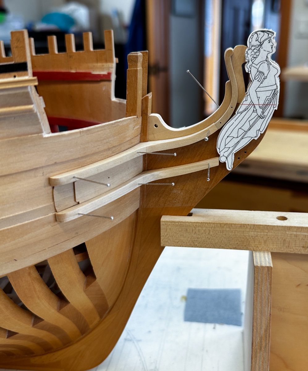
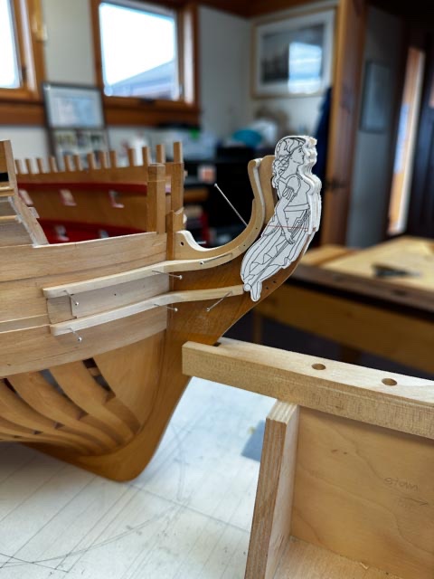
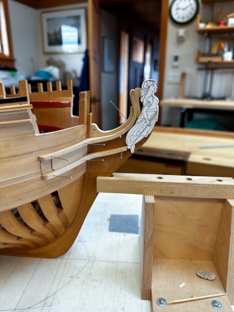
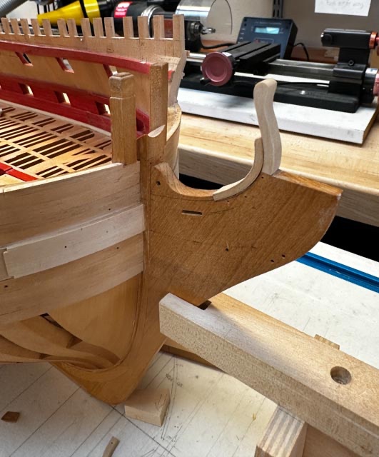
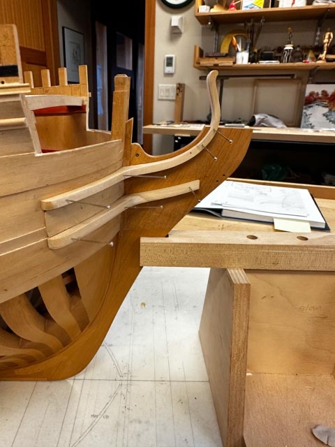
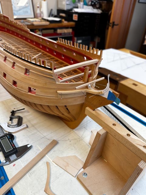
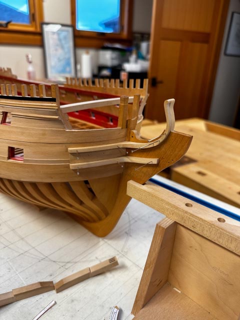
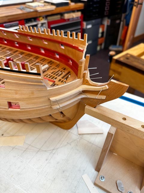
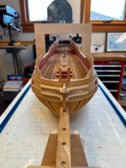
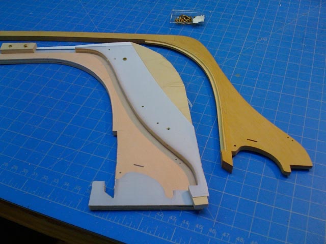
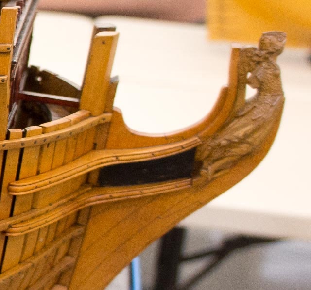
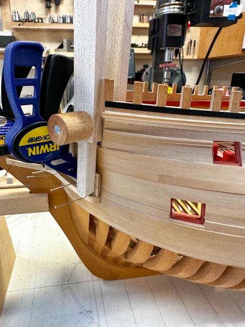
 Thanks so much for the kind comments, Yancovitch and Steve. Slow but steady! In my last post, I express doubts about the way I had managed the hair bracket, sitting tenuously on top of the knee at the stem. After pondering it a while, I decided there was nothing for it but to cut down the top of the knee that I had shaped in 1998 when I started construction (see image below). It was too short for the hair bracket, the gammoning slot and the hole for the mainmast stay collar were in the wrong locations. To this day, I don't quite know how I got that so wrong. I might have copied something out of Lavery's book on the Bellona, which I have subsequently discovered is not accurate enough to build a model from. And I started construction years before I finally started drawing more accurate drawings--always a mistake! So, I made a complete new piece, combining the hair bracket and a carved ornamental piece that stands directly behind the figurehead. It seemed more solid the two together, and they are the same thickness relative to the figure head: And after a lot of faying and tapering, the new core for the hair brackets now holds everything firmly together. I made up a dummy of Bellona (don't tell her I said that, she is supposed to be a very scary warrior...), just to see how things are starting to fit together. The first image below shows the new core piece still covered in the paper pattern, showing the bas-relief carving to come on the piece behind the figurehead (she is pulled away from it a little in this photo). It also shows the captain standing on the cheeks. Gives a good idea of the size of the figurehead. And here are parts starting to fall into place: I have been reading David Antscherl's excellent explanation of how to carve a figure head in Volume II of the Fully Framed Model. I might start with the maquette, and see how it goes... I have pondered what wood to use, to carve the figures on the ship. My boxwood is not buxus semperivens, the stuff the old modeler's used, and that David recommended when he first wrote his book. But I can find no supplier anywhere in the world of buxus semperivens anymore. I know my boxwood is from South America, but I don't know its actual species. It seems to be stiffer in relation to what others have written about working true boxwood. I think it will have to do. And I can always blame a bad outcome on bad tools or bad wood, not lack of skill!🙂 Best wishes, Mark edited with higher resolution image here:
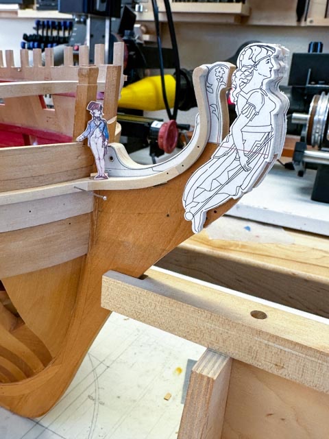


-
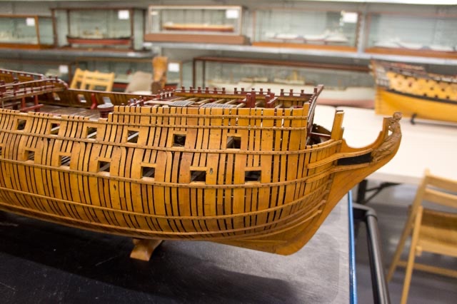
Marc, Thanks so much for finding that video. Astonishing. One of the most striking items for me is the frame construction system. It does not use sistered frames and a frame and space arrangement as in the 18th century English ships. The single frames abut each other, alternating floors with futtocks and eventually top timbers. It is framed just like the English Admiralty dockyard models of the 17th and early 18th century. Franklin's Navy Board Ship Models book discusses this full size practice as the likely source for this modeling technique, and now I see it firsthand. So the framing of my model of the Bellona replicates this actual practice; I hadn't quite realized that before. And you can only imagine what it was like to construct this before chain saws and cranes.... Mark
- 2,699 replies
-
- 4
-

-
- heller
- soleil royal
- (and 9 more)
-
Looking really nice, Chuck. I missed it somewhere; how did you make the master for the figurehead. Is that clay or wax? Best wishes, Mark
-
Thanks, Gaetan, someday when I get further along, I would be interested in studying French ships of the period. Always fun to see what is universal, and what is culturally different! Further progress today. I finally got in the second layer of the hawse lining, ready for drilling the hawse holes: And now on to that pesky support for the hair bracket. I tried letting a liner down into a rebate I cut today on top of the knee, but I may sleep on this. It seems flimsy, kind of cobbled together. I may consider making the entire core in one piece. A decision for tomorrow!
-
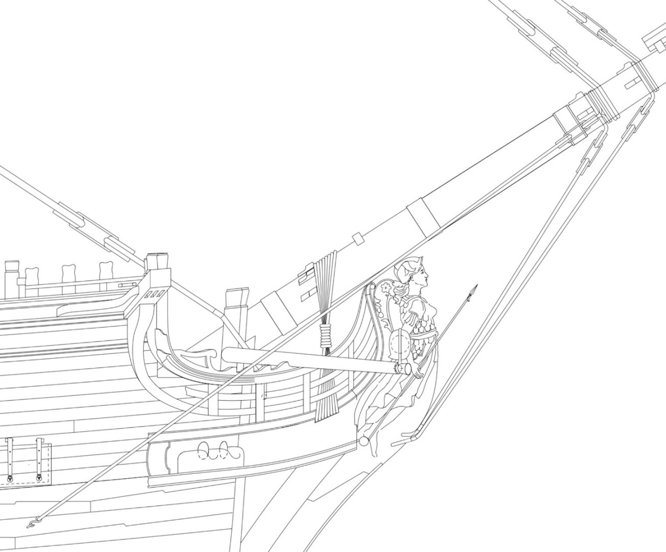
Hi druxey and Alan, The last image was a little misleading; the bowsprit shroud coming across the drawing make it look like the bowsprit was lower. The drawing below without the shroud shows the actual clearance I am working to, which is from the original Admiralty drawing. While referring to the previous drawing, you can see my drawing of the bumpkin or boomkin has no stays or other supports. Lees' Masting and Rigging pages 130-131 says that no rigging was fitted in the first years of the bumpkin, although he doesn't say when it first came into use. The few models I have seen of ships contemporary to the Bellona ca 1760--like the Thunderer-- do not show any rigging other than the shoulder block for the fore tack. Does anyone have any further model examples or further evidence of what may or may not have been used as additional stays for the bumpkin around 1760?
-
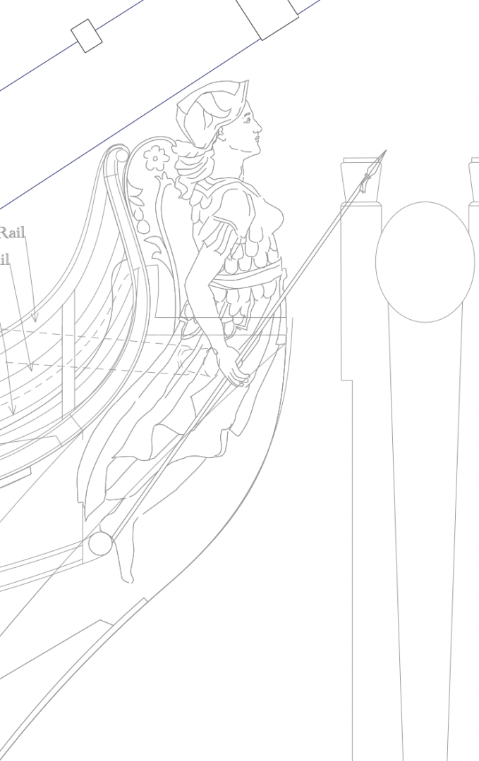
Waiting for the glue to dry on the port upper cheek assembly, I looked more carefully at the area around the figurehead, double checking on the heights for clearance for the bowsprit, and also where the rigging will begin to fasten. Better to catch problems now, as parts are beginning to fall into place. I redrew the Bellona figurehead, with more detail that might begin to lead into the carving--at the very least, a blank to make sure everything fits. And, I did discover a mistake from 25 years ago. I marked and cut the slot for the gammoning in the keel when I first started construction. Now I see that I thought was the fore end was actually the aft end of the slot. So it is exactly its own distance back from where it ought to be! It will take some fine work to fill the slot and cut a new one. Don't tell anyone! Here is an updated drawings with the new Bellona figurehead, and the beginnings of rigging at the bow:
-
Greg's and druxey's gluing ideas worked well. Tiny drops of carpenter's glue between the piece and a sheet of plywood held everything firmly enough to sand fair on three sides. Isopropyl removed it from the ply, and as the British say, "Bob's your uncle!" Good trick for refining small delicate parts. Glued together on the hull, still not fully faired to each other: then glued down on plywood: Faired, and pinned back on the hull: This piece reminds me of the great quote on Remco's HMS Kingfisher site: "Treat each part as if it is a model on its own, you will finish more models in a day than others do in a lifetime." Mark
-
Hi Håkan, Thank you so much for your kind thoughts. I started a log on June 5, 1998, when I first started the actual construction (as opposed to the drawing for several years previously), noting issues I was working on, how I solved it, and how long it took. But the log quickly fell by the wayside. I still worked out details in it, but no longer kept track of time. And there are many months-and even a few years--not even accounted for. Like you, I realized it is the journey that counts. The Bellona is like a good friend, someone to spend time with, and who continues to reveal secrets the more I study and work. I am not sure what I would do with my time if ever I finished. I am too old to start another multi-decade project. So I think I will just drag this out, hoping I finish right before I can no longer see, or I have to deal with shaky hands. And great to hear from another left hander! Best wishes, Mark
-
Thanks so much, Greg, just what I needed to know!
-
Hi Alan, Looking great! Something that helped me put in the deck clamps was a small jig that could reference against the gunport cills, and then draw a mark at the correct distance down for the clamp location. Assuming the gunports are well faired, the deck at the sides will always be parallel to the ports. At least it was in the Bellona. Mark
-
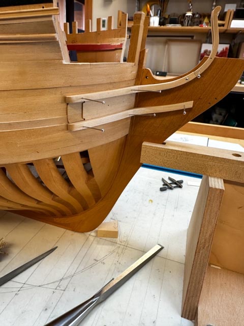
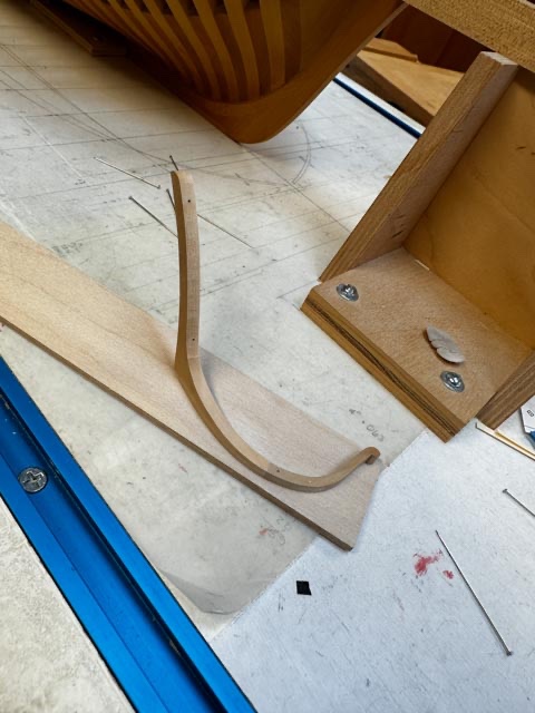
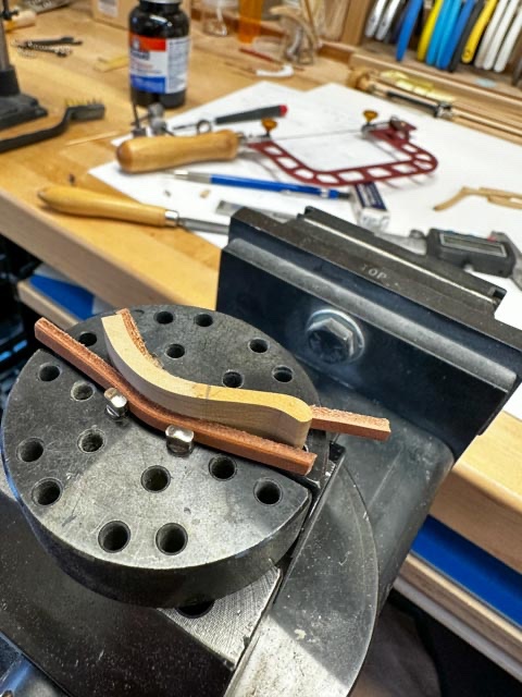
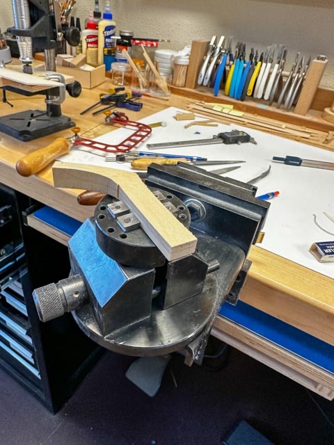
The work on the cheeks and hair brackets continues. Getting a grip on these irregular shaped objects is a challenge. My GRS vise has saved the day, using small strips of leather to pad against the pin jaws. The biggest challenge by far--and still continuing-- has been fairing the upper cheek into the hair bracket. The photo below shows a paper template taped to the knee, which gave me a rough idea of the cheek's upper curve, but it was only approximate. I found greater success once I made the hair bracket and the core behind it, and temporarily pinned and tacked these to the knee. then I could sight the curve of the cheek and adjust accordingly. Getting closer: But it still needs a final fairing between the cheek and the hair bracket, which I think needs to be done off the hull. My thought is to tack the two together at their joint, then temporarily glue them down onto a flat surface so I can smooth the two pieces together. Can I get some technical advice? I have read about modelers gluing delicate pieces to a base with paper between, to be worked on. is this carpenter's glue, full strength or diluted? And then how do you then get the delicate piece off the base, and get the glued paper off the back of the piece? I don't want to soak these in water. Is isopropanol used? Having invested so many hours into these pieces, I don't want to mess up at this last stage! Mark
-
Looking great, Siggi! Your painting on the friezes and headwork is masterful. And inspiration for us all. Mark
-
Hi druxey, yes, that does help. I see one of the biggest issues here is getting the fore and aft edges of the core and the two hair brackets to be flush with each other. Maybe I make the hair brackets first, glue them to the core, file them flush to each other, glue the whole thing down onto the top of the knee and then attach the cheeks. otherwise, I would be trying to file the core and the hair brackets flush to each other while on the ship--not a pretty idea to contemplate!
-
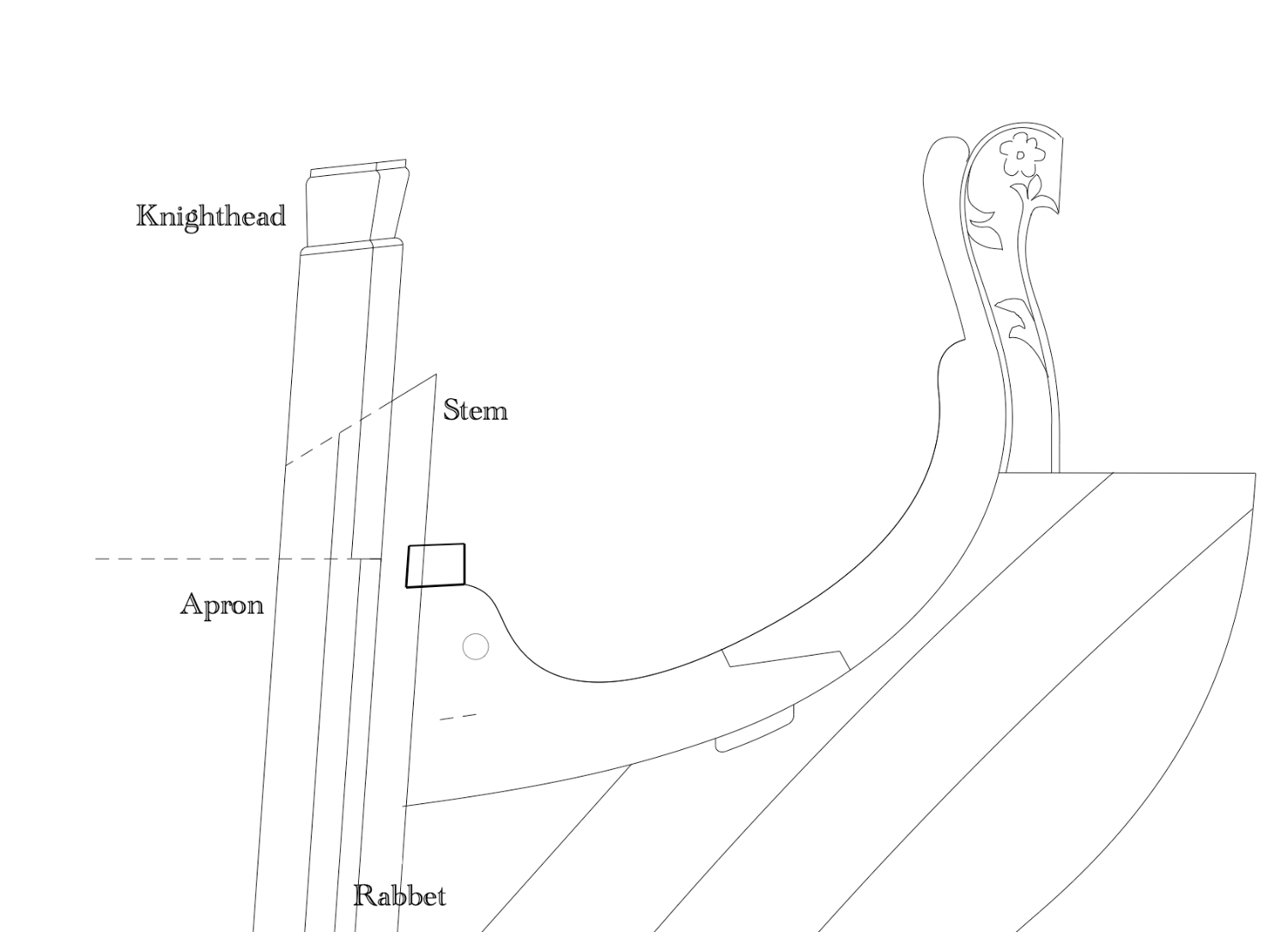
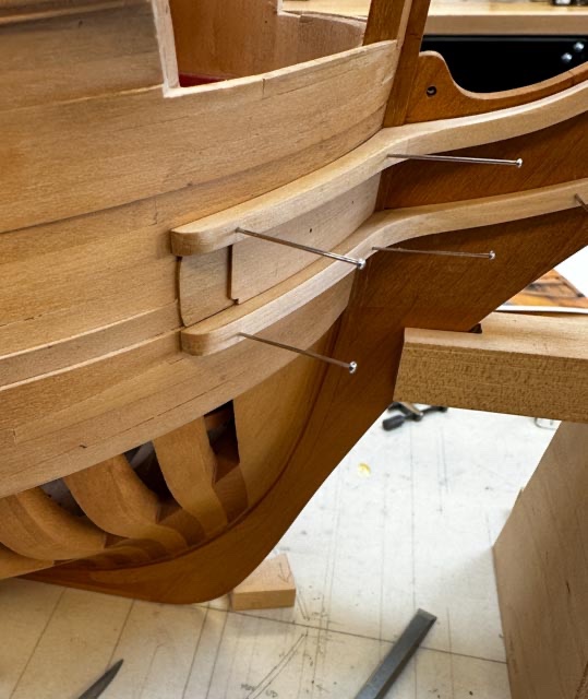
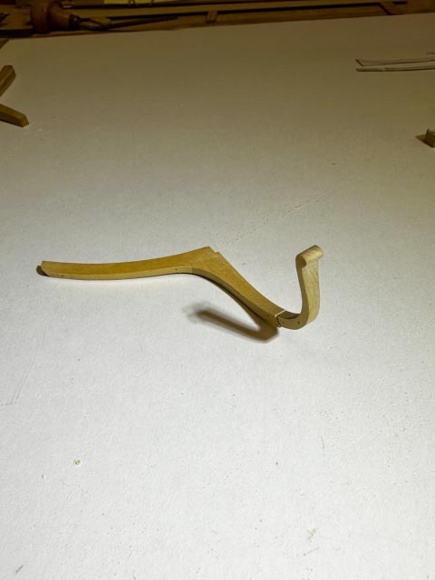
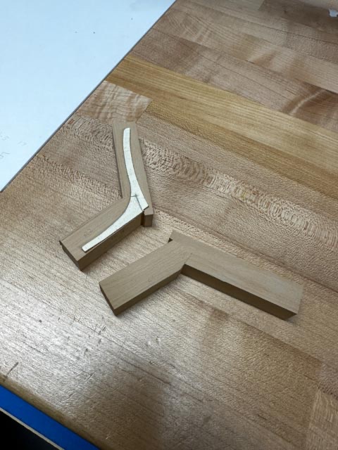
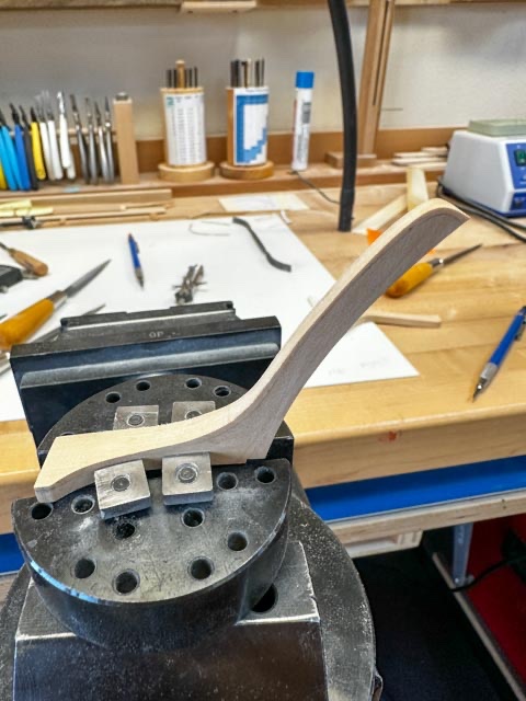
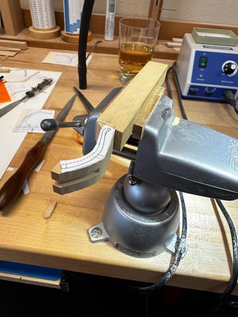
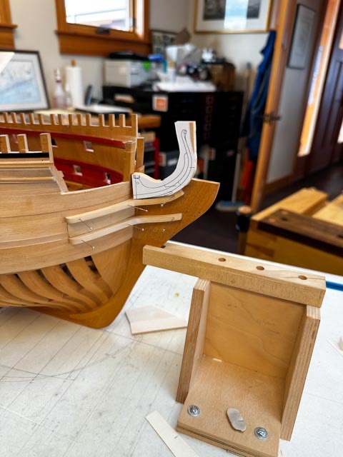
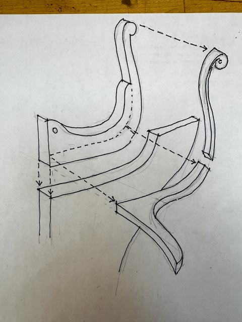
The cheeks saga continues. I finally got both cheeks, both sides, close to finish size and pinning in place: I made the cheeks up in two parts, hopefully to get the grain to run roughly parallel to the scratch moulding still needed to be done on each outboard surface: I also used, for the first time, my handy vise attachments that hold irregular pieces. I don't know how else I would ever have held these multi-curved surfaces for shaping: Then came the awful discovery that I had cut the top of my knee at the head to the wrong profile. Fifteen years ago I made my best guess at this shape (photo from 2008): And then as the cheeks neared completion, I started wondering how the moulding continuing on from the top cheek--the hair bracket-- would be supported for its full length to the scroll at the top. I looked again at the original Bellona model, and saw there had to be a much higher core up from the knee of the head, between the hair brackets and abaft the figurehead: I tried making one piece, with a slot to slip over the knee, but soon gave up on that as pretty impossible to cut a slot tapering in two directions while keeping it aligned athwartships and fore and aft: I finally realized that the top of the knee should have looked more like this upper left piece in the drawing below: So tomorrow, I will see how I can fit my retro piece onto the top of the knee, between the upper cheeks: Wish I had understood that 15 years ago, and good thing I am not in a hurry....
-
Thanks so much, Marc and druxey. While our digital resources today open up research to more of us not close to the major libraries, it is still sometimes frustrating not to be able to dig into an archive and find just the right item. So we do the best we can with the help of people on this site! druxey, I am glad you have looked this over and think I am headed in the right direction. I will fix the square hole in the wheel. I still don't quite understand what the solid piece is that guides the burrs once they come around the rowle at the bottom; could it be a solid piece of metal the width of the tubes, bolted between the metal side panels supporting the rowle? And I wonder what holds in place the lower end of the return tube, just floating in the air in Lavery redrawing of the 1708 Resolution? When I drew the chain and burrs at different points coming around the rowle, I could see just how much that chain would have clanked, tightening and loosening. Amazing it didn't come off more regularly! Best wishes to both of you for the new year! Mark
-
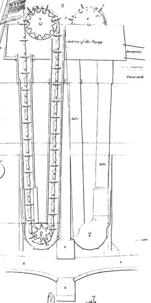
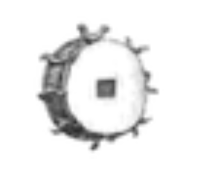
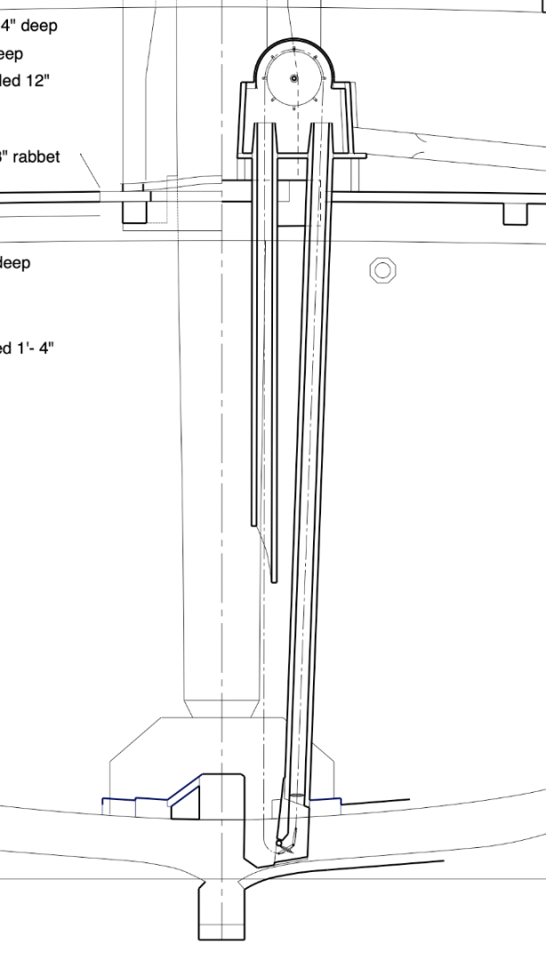
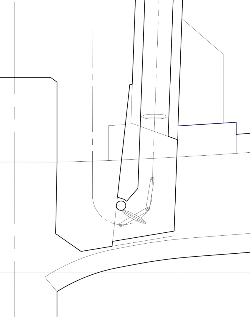
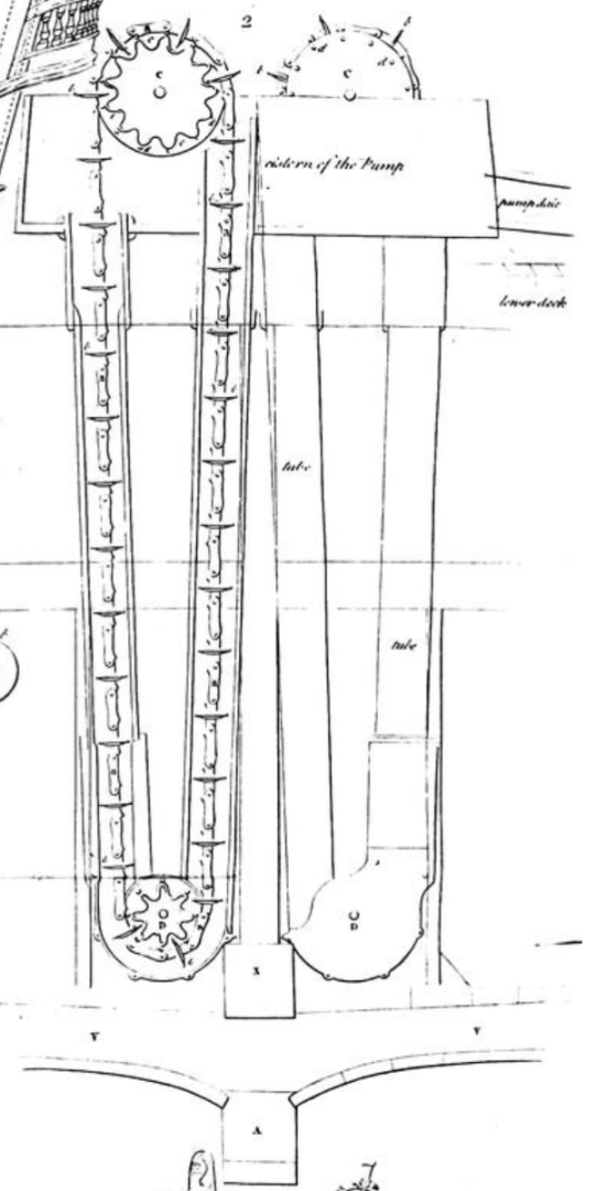
Press release March 1, 1760; "The Admiralty just learned that the proposed Cole-Bentinck chain pump will not be available for another 10 years. The HMS Bellona currently being fitted out in Chatham Dockyard will have to install a standard pump". I bothered me that I was recently showing a pump designed a decade after the Bellona's launch, even though I am trying to show her as she was designed. I looked again at sources, and found information I had overlooked in Lavery's Arming and Fitting, page 71; a redrawn section through the Resolution of 1708. It is the only drawing I have found of a pump before the Cole-Bentinck, and so I will go with the idea that this pump was probably closer to the one installed in the Bellona in 1760. Lavery points us to some drawings in Blanckley's Naval Expositor of 1750. Taken from the Gutenburg permission free ebook online, here is the key idea at the upper wheel. These sprockets are driven into a solid elm wheel, over which the chain rides. With this, and then interpreting as best I can the drawing of the Resolution, here is my best shot at the design of a pre-Cole-Bentinck pump, ca. 1750. Distinctive elements: 1) the return tube does not go all the way to the lower end of the pump; 2) the bottom of the pump rests right on the outboard planking, set into a deep slot beside the keelson; 3) it has a bottom roller, like the later Cole-Bentinck design. I can see how the chain and burrs would bump over that, tightening and loosening the chain and causing the problems mentioned in various sources regarding this traditional pump. And the chains have no mechanical hook to the sprockets, allowing the slippage mentioned earlier. But at least this is closer to authentic for 1760 than I have managed so far. Unless anyone has come across a contemporary drawing of a circa 1750 pump, this is my best bet... Mark
-
Hi Marc, I have been away from the website for what seems like such a long time, with life issues that have arisen in abundance these last couple of years. Anyway, I recently had a chance to look over your posts in more detail, and I can say you continue to set the very highest standards for research, construction and painting. Truly a work of art emerging! And a thrill to follow you down the paths of research on these very complex 17th C. ships! Mark
- 2,699 replies
-
- 6
-

-
-
- heller
- soleil royal
- (and 9 more)
-
Hi Alan, Looking great. That last little bit of hull at the stern is a more complex form that one would ever appreciate from drawings alone. it manages to go from curved in two directions to a straight edge at the counter timber in an almost imperceptible transition. I had to make oversize and shave down when I could see the overall form of the hull. Mark
-
Gary, I enjoyed looking over your latest photos. The build is really coming along well, and nicely photographed! Here's looking forward to a good and productive new year! Mark
-
Thanks, druxey, That earliest version of the Cole-Bentinck pump illustrated in Falconer would certainly have left a lot of water in the bilge, since the height at which water is captured is about level with the top of the keelson. I can see why the subsequent modifications included dropping the pump base as far down as possible. It is quite intriguing to see the evolution of a technology, and also to see an early version of a user's manual that you refer to in Lavery's book. My brother once worked as a technical writer for a software company, and the writers complained that the engineers kept tweaking the software right up to the point of release, leaving the written manuals sometimes incomplete and inconsistent. I wonder if Cole and Bentinck kept tweaking their design after their user manual was produced?🙂
-
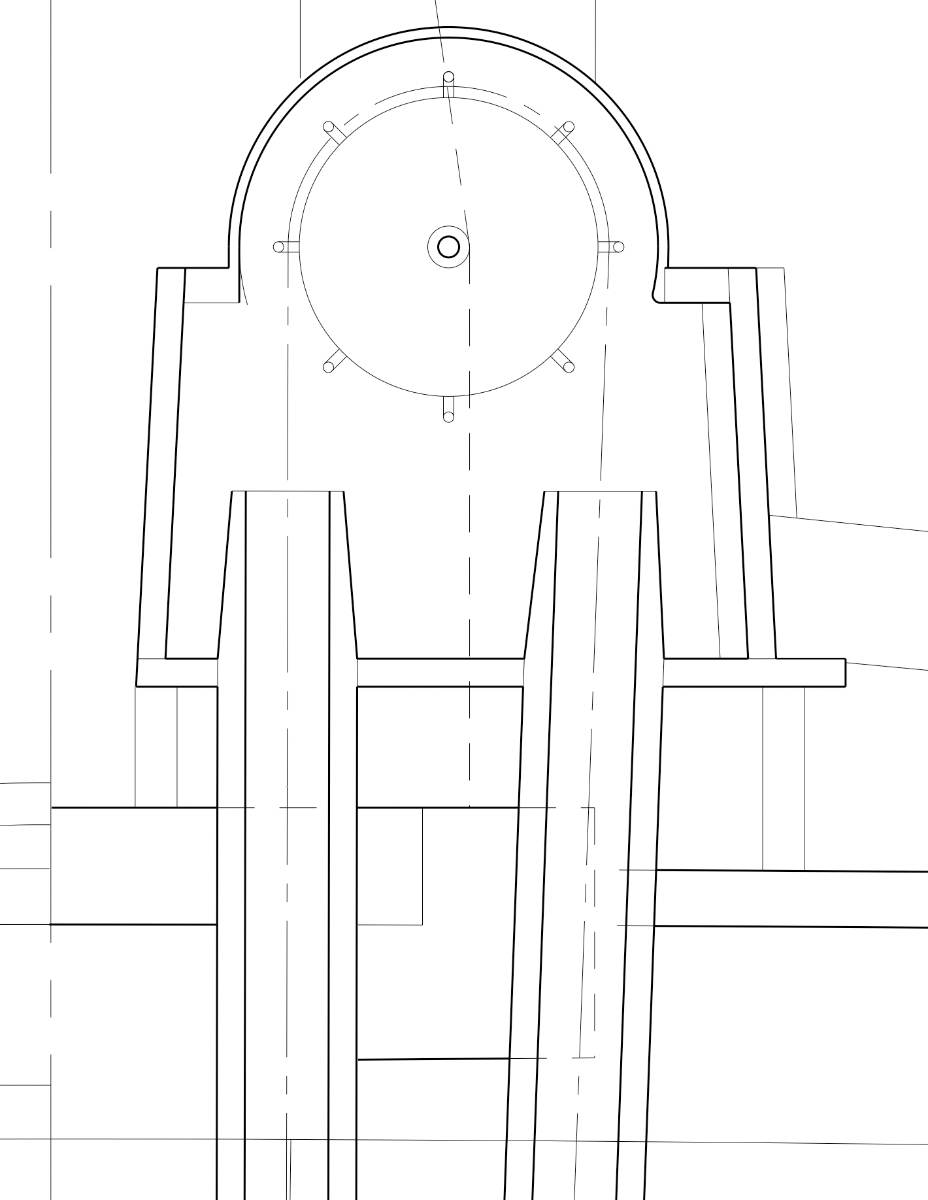
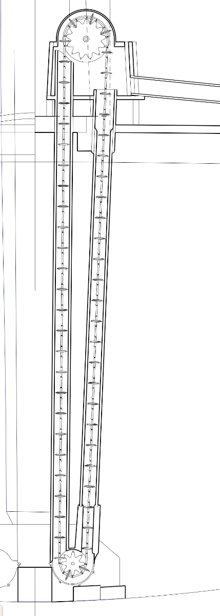
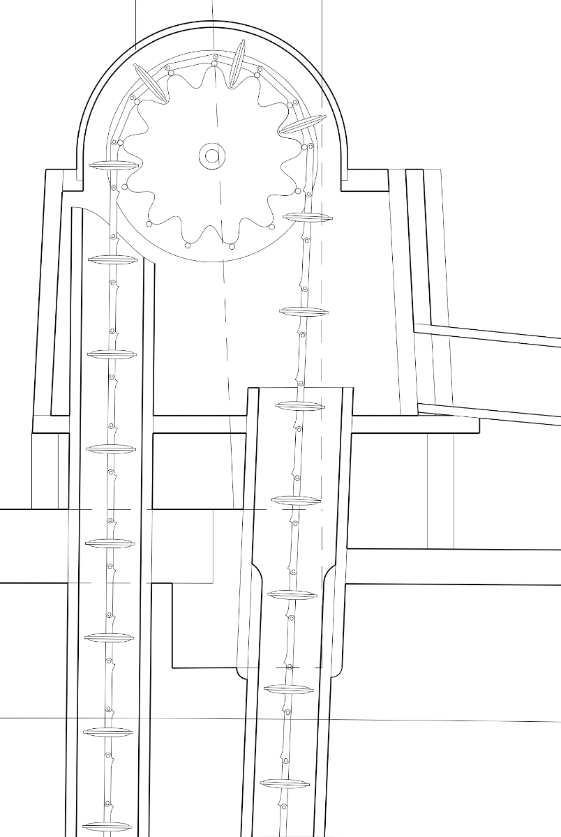
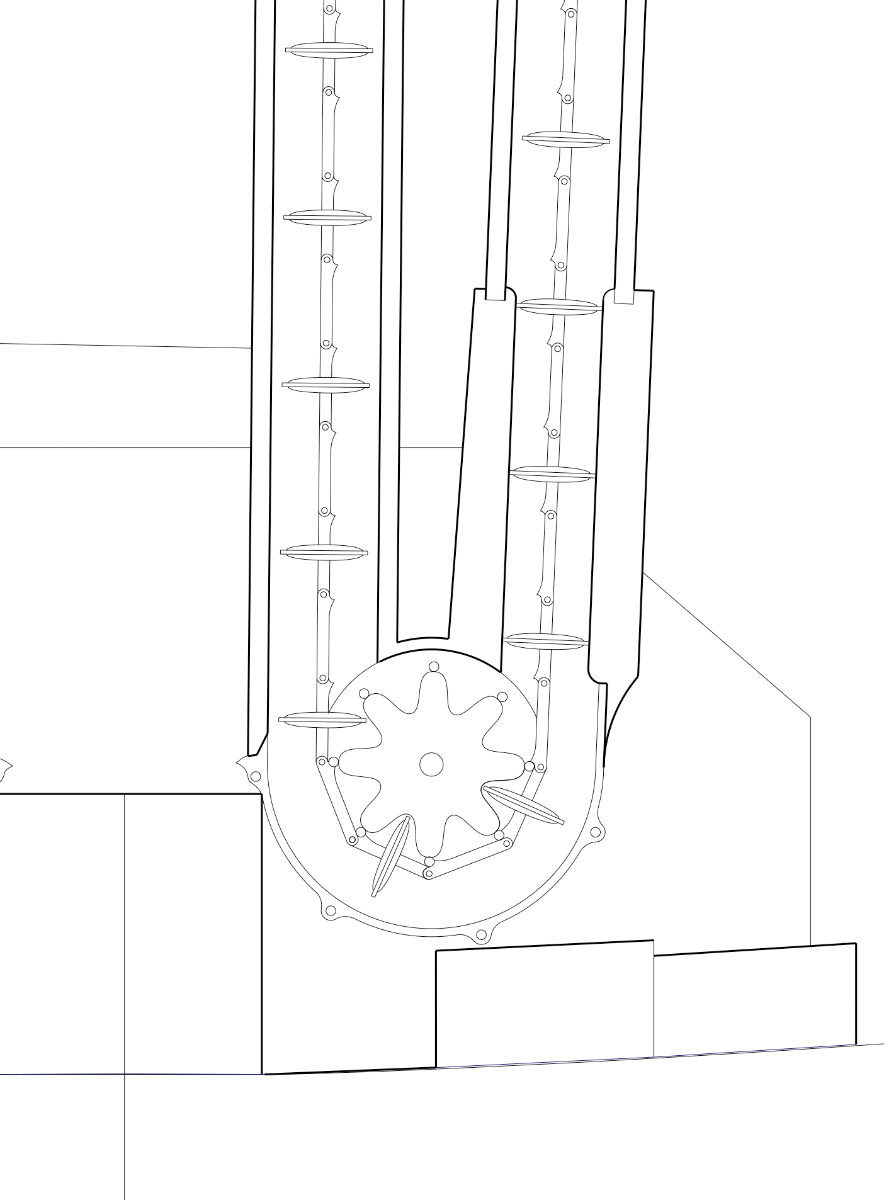
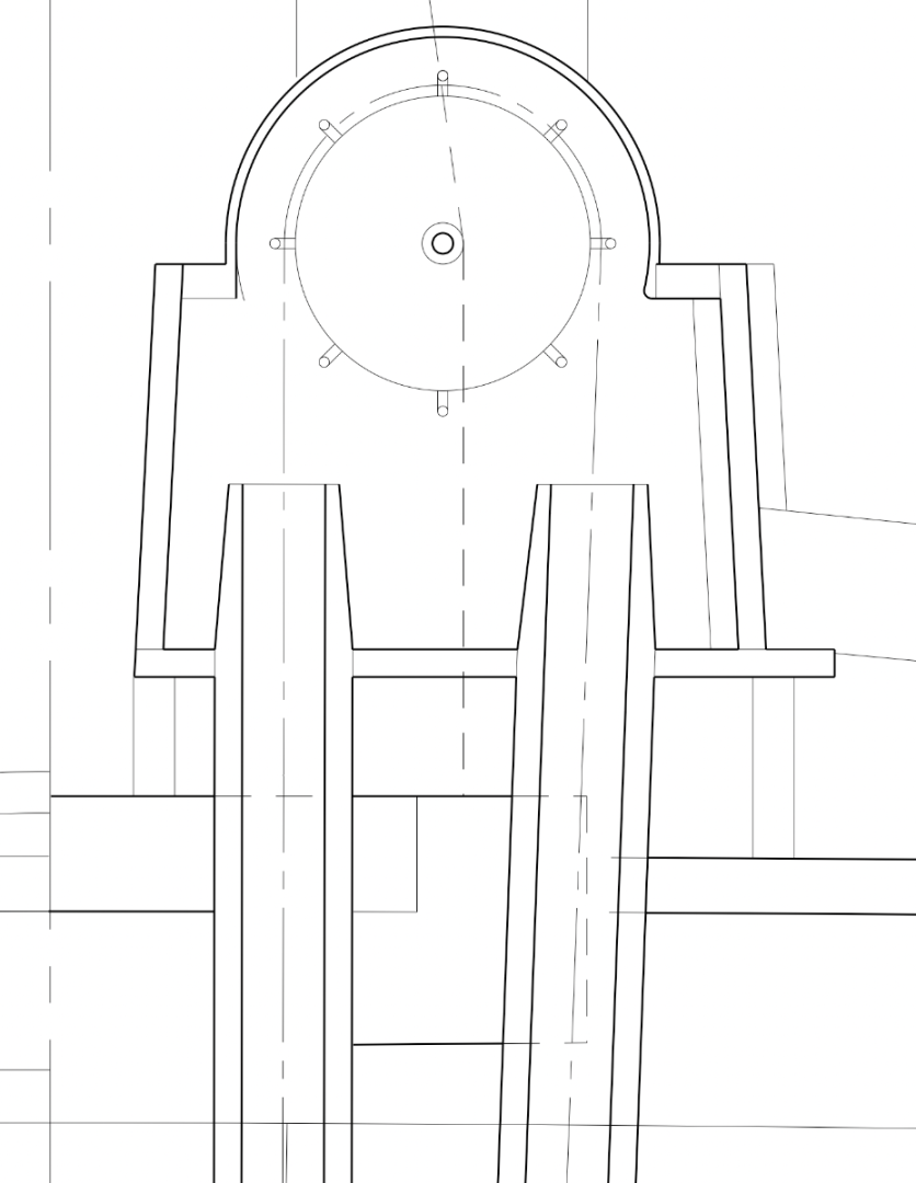
While waiting for steaming and glue to dry, I tackled a drawing project I had long, long put aside, the pumps. I am not installing anything except the cisterns, but I was always curious about these. So I did a little digging in Lavery's Arming and Fitting of English Ships of War (pp. 66-76), Peter Goodwin's Construction and Fitting of the English Man of War (pp. 138-142), David Antscherl's Fully Framed Model (vol. II, pp. 96-102) and Dodds and Moore's Building the Wooden Fighting Ship (p. 100). The year of the Bellona's completion, 1760, appears to be in a transitional period from earlier, inefficient pumps to the much improved Coles-Bentinck which was first tested in 1768 and underwent a number of improvements over the next few years. There is less information available in these printed resources for the pumps before the Coles-Bentinck, so I was left wondering what the Bellona pump more exactly might have looked like. The only primary document drawing I could find closer to the launch of the Bellona is plate VIII in Falconer's Dictionary of the Marine published 1769, which I have shown here from the Guttenberg ebook project. Brian Lavery says this has features in common with the Coles pump, but with some notable differences like the cogged wheels which are not in the later Coles-Bentinck pumps. He says that "Either this is an early version of the Coles pump, or it is one of many other inventions of the period." (p. 72 footnote). Falconer's clearly identifies this illustration as the "naval chain-pump, by Mr. Cole, under the direction of Capt. Bentinck", which Falconer says works much better than the earlier pumps. It must have been one of the very earliest versions, since the cogged wheel disappears in later versions. And Falconer is publishing this just a year after the initial test of the Coles-Bentinck pump. Lacking detailed information on pumps before this one in Falconer, I decided that this would at least be closer to the Bellona date than the later, well illustrated Coles-Bentinck pumps. Shall we assume that the Bellona installed this improved pump when it first become available a decade after launch? I quickly discovered that this drawing is not an accurately scaled drawing. The distance from top to bottom is way too short relative to the sizes of the cisterns and pump tube diameters. So I took features from this drawing and tried to accurately scale it to the actual hull. Things I learned in this exercise. 1. The cogged wheels do not engage or drive the disks as they go around. There are bolts at the point of each tooth that actually engage hooks on the chain links. I see why they quickly abandoned the cogged wheel and kept the bolts and hooks. 2. The disks are of a smaller diameter than the tubes everywhere in the pump EXCEPT at the most critical part, a chamber at the outboard base of the pump where the disks have a tight fit (last illustration below). This makes sense, after thinking about it. A tight fit all along the pump would have created a great deal of friction in the machine. It only needs to pull up water within this chamber which then holds up the column of water from the chamber to the cistern. Very, very clever. 3. This drawing curiously holds the bottom chamber up from the floor, indeed, hanging off the keelson. Later pumps try to get right down to the floor or even cut into the frames so the point of pulling up water is as close to the bottom as possible. This pump will leave a good puddle in the bilge that it cannot reach. However, when one considers that the hull is usually heeled over, it is probably getting close enough to the bottom of the bilge water. If anyone has come across sufficiently detailed drawings of pumps in service just before this pump, please share and I will redraw. Until then, the Bellona gets a pump refit....🙃 Oh well, back to the model....


-
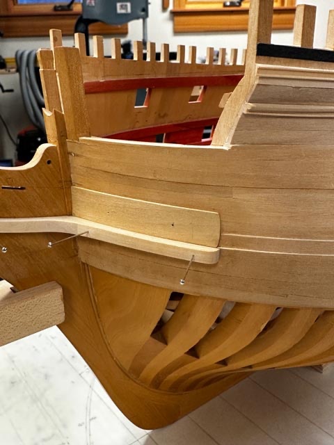
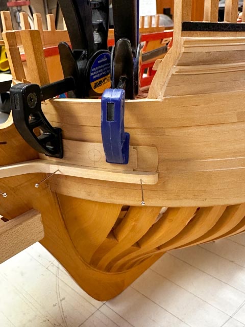
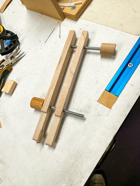
Thanks so much, Gary and Alan, just when I think I know the name of everything, then I discover yet more to know... The lining proved yet more difficult to fasten than I expected. I could not get a clean shot at clamping the outboard end firmly to the hull. So I made a special clamp, with a pad shaped to the end of the lining. either my clamps could not reach that far over the edge, or they were so fat I couldn't see if things were bedded home or not. So thin legs on the new clamp gave a good view and also applied pressure at just the right place. Then it all worked out: And a first look at the second layer, which still needs steaming. And the hawse holes penciled in: Mark
-
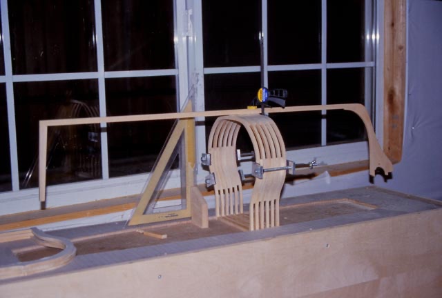
Thanks so much, everyone. Gary, I am getting ditzy in my old age; I forgot that you had already tackled this interesting detail and turned out a beautifully crafted solution. thanks again for showing this. Greg and Mike, good advice on using the delicate mills. Mine got misdirected in the mail, and won't get here for another week. Then I will play around with it for the sheaves in the beakhead bulkhead stantions. Those were going to be a bear to construct at 1:64 scale without this mill... druxey Mike and Yves, I steamed the first layer and it worked perfectly, thanks for directing me to this solution. It was just too hard to fay the lower edge to the cheek with the piece springing away all the time. druxey, do you happen to know if there is a name for this additional plate on the face of the hawse holes. I don't recall seeing it named anywhere, but then my memory is not the greatest lately. And have you seen anywhere how it is actually constructed? Carved out of one piece, or also laminated in real life? Happy holidays, everyone!
-
Hi Greg, I add my congratulations to everyone else's. You have set the highest standard for model builders around the world. An inspiration to look at. Mark
-
Thanks, Mike. BTW, once I get the 1/32" mill, does it need to be fed in tiny amounts to avoid breakage, or is it pretty robust?