HOLIDAY DONATION DRIVE - SUPPORT MSW - DO YOUR PART TO KEEP THIS GREAT FORUM GOING! (Only 13 donations so far - C'mon guys!)
×


SJSoane
-
Posts
1,649 -
Joined
-
Last visited
Content Type
Profiles
Forums
Gallery
Events
Everything posted by SJSoane
-
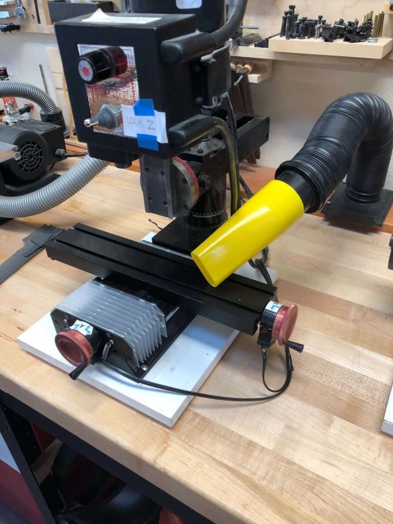
 Gary, nice! Is that little funnel at the end nearest the lathe also part of the Loc Line system? Mark
 -
Spectacular work, Gaetan, both the build and the photographs! Mark
-
HI Gary, I look forward to seeing it! Mark
-
HI Gary, I am also looking for a better dust collector idea for the mill and lathe. My current setup doesn't work very well. The nozzle gets in the way, but at the same time doesn't really stay close enough to pick up much. Mark
-
Gary, do I see correctly that you have mounted your Digital readout right on the face of your Sherline mill (9th photo down)? Interesting! How did you fasten it on? Mark
-
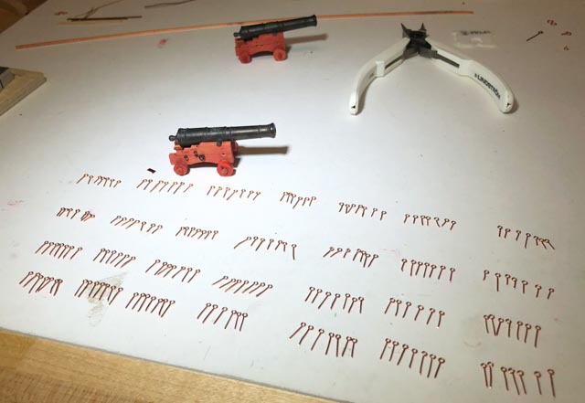
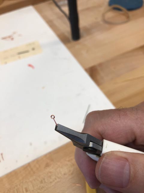
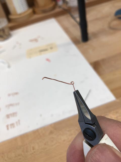
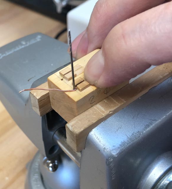
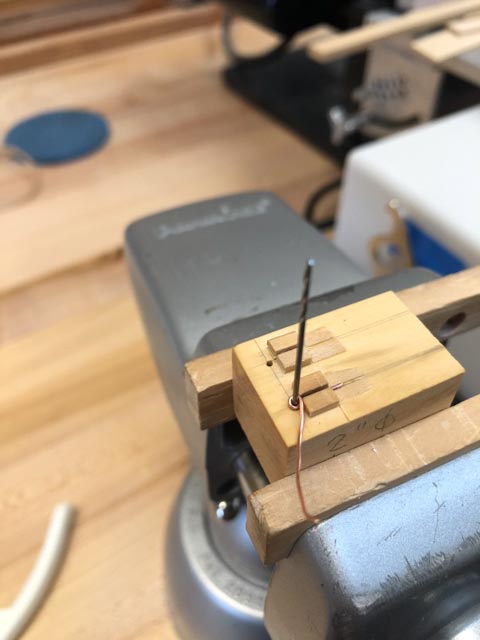
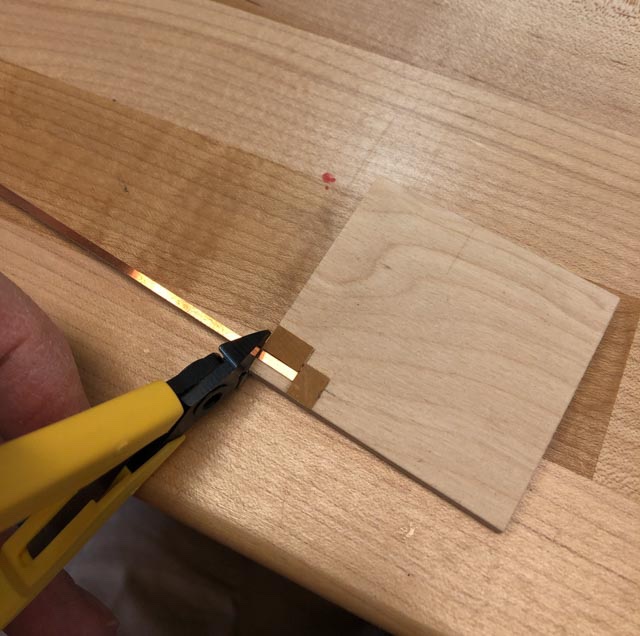
druxey, could it be the cap square on that carronade was cast, not bent from sheet? I never thought of doing that. A good way to pick up the detail of the hinge and clasp... I spent a good day bending up eye bolts for the gun carriages. I made a jig inspired by Alex M (HMS Sphinx), who got it from a German modeler Günter Bossong http://www.minisail-ev.de/fibel/fib-03-09/fib-03-09.htm. It has a slot just wide enough for the leg of the eyebolt, and a drill the correct size of the inner diameter of the eye. A piece of copper wire of the correct diameter is bent at right angles and put into the jig, then pulled around the drill bit (the hole not being used is for the larger diameter eye bolts for the quickwork, still to come): The wire is wrapped all the way around the drill bit, and pressed down on top of the leg: The loop is then grabbed with pliers and cut with micro angle cutters just where the loop hits the leg: a quick squeeze in parallel jaw pliers to flatten out, and voila, Bob's your uncle: I see that one of the positions with the greatest job security in the 18th century British shipyard would have to be the guys who made the eyebolts and rings. Here are 196 eyebolts, just for the 28 cannon carriages on the gun deck. Add in another 28 for the deck, and 112 in the quickwork, and no rest for the weary... Mark
-
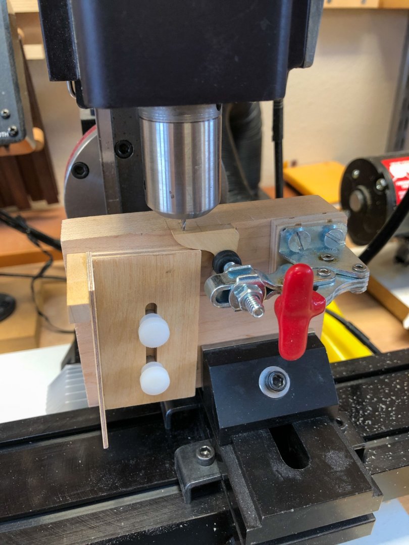
Thanks, all fellow OCD people out there. druxey, what missing hinge and latch? Like Gary, I was hoping no one would notice. Could it be they were just printers' smudges in the drawings?😉 I have justified this omission to myself with the story that I need to insert these barrels through the gun ports years from now, and these additional bits will break off before I get there. Maybe, maybe, I will see how to do this for the guns on the upper decks. Gary, I can't pronounce complexititus either. And our British friends would probably have a different pronunciation for it anyway... Guy, yes, you have it right. The carriage sides slope 2 degrees inward each side at the forward end. And you are also right, at 3/16" scale the angle is like a rounding error, hardly visible. But given my complexititus syndrome, I just had to see if I could make the angles work. I did indeed drill the holes for the dowels in the jig at 2 degrees left and right, using angle blocks under the piece mounted in the mill vise. Mark
-
Gaetan, those are beautiful engravings. Were they drawn around the time of the ship 1720, or much later? Mark
-
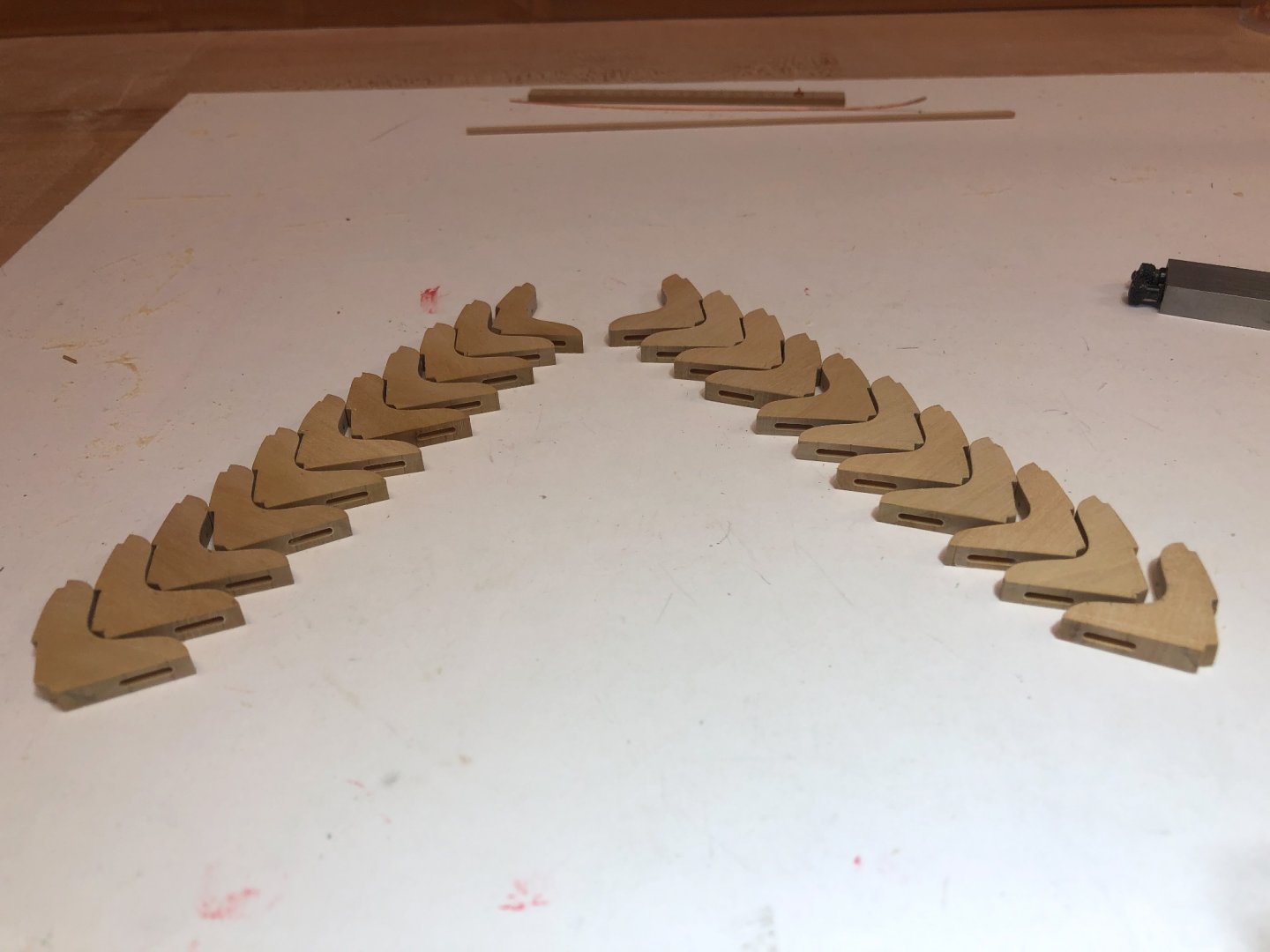
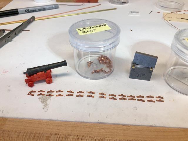
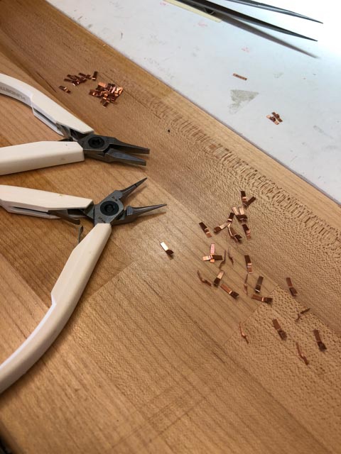
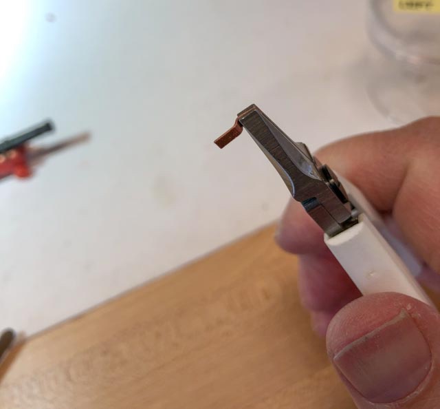
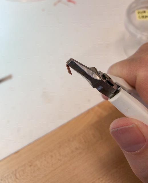
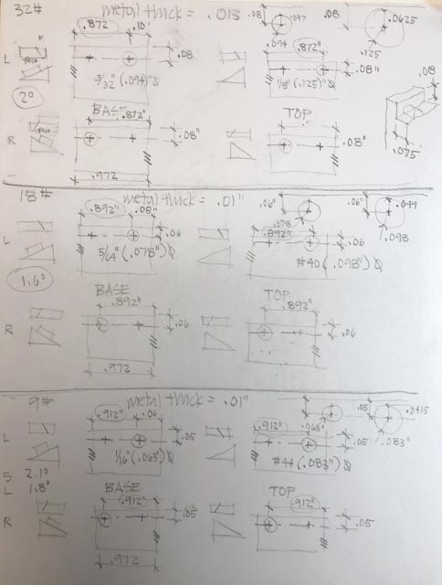
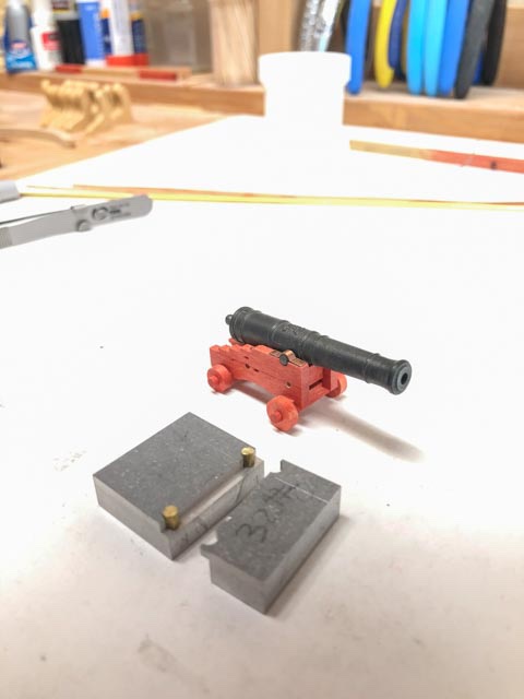
Thanks, everyone. Viewer warning: the following is for obsessive/compulsive people only.... This morning I adjusted my jig a little, and it really did make noticeably handed parts, left and right. So I proceeded to crank out cap squares. step 1: cutting to length. A little stop jig made quick work of cutting all of the parts to the same length. step 2: the blank needs some rough bending before putting it in the jig. I measured 7" (real size for the fore end of the cap square) on the end of my pliers, and made a 90 degree bend. This ensures that the part keeps all of the right proportional relationships once it goes into the jig. Step 3: chain nose pliers are used to form a rough curved bend next. I end up with a pile of S curved blanks, ready for the jig: Step 4: into the jig, with the 7" length inboard of the jig, and the 90 degree bend tight up against the dowel. A tight squeeze in a vise, and perfect cap squares form: 28 identical left hand, and 28 identical right hand. In a couple of hours. Way more fun using a jig, even though I did struggle trying to design the jig, as seen in the previous post. The jigs for the 18# and 9# guns should go a lot faster, now I know what I am doing here. Mark
-
I am going to try to get some help for my debilitating psychological condition, complexititus....🧐
-
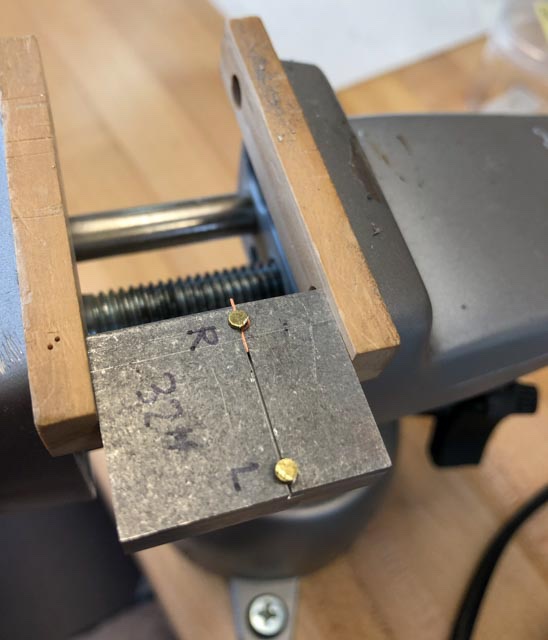
I still can't help myself. I spent a couple of days working on a jig to make the gun capsquares. I did manage to put something together, making left and right hand pieces (because of the angle of the carriage sides). It got complicated, working out how to get the male and female parts to line up when the holes were drilled at opposite angles: It worked: But the angle barely shows at this scale, not worth all of the extra work. Tomorrow, I will try simplifying this to a 90 degree angle used for both sides, then make the jigs for the other two gun sizes before I forget how I did all of this.... Mark
-
Hi Siggi, I am just catching up with your posts. I missed these for some time, after the scratch build entries were divided into decades. I forgot that your ship predates 1750! Apologies. The work is looking great, up to your usual very high standards. The gun deck photos make it feel like we are in the real ship. The pillars at the centerline look terrific and very consistent even though you turned each one by hand. Did you use a special shaped cutter, or just normal tools and a template to check measurements? I am facing this fun challenge soon myself. Best wishes, Mark
-
Thanks so much, Alex, that was a very interesting article, and Google translate worked very well. I am also currently working on a jig for the cannon capsquares, and the article gave me a few things to think about. Best wishes, Mark
-
Alex, Beautiful work, as usual from you! I continue to be inspired by your craftsmanship, and also your methodical ways of fabricating things. I have recently worked out a version of your jig for making eyebolts. It works well. You are very ingenious! Mark
-
Nice, druxey! By George, you are right! I wonder why my mind always seems to go to the more complex idea first.... Mark
-
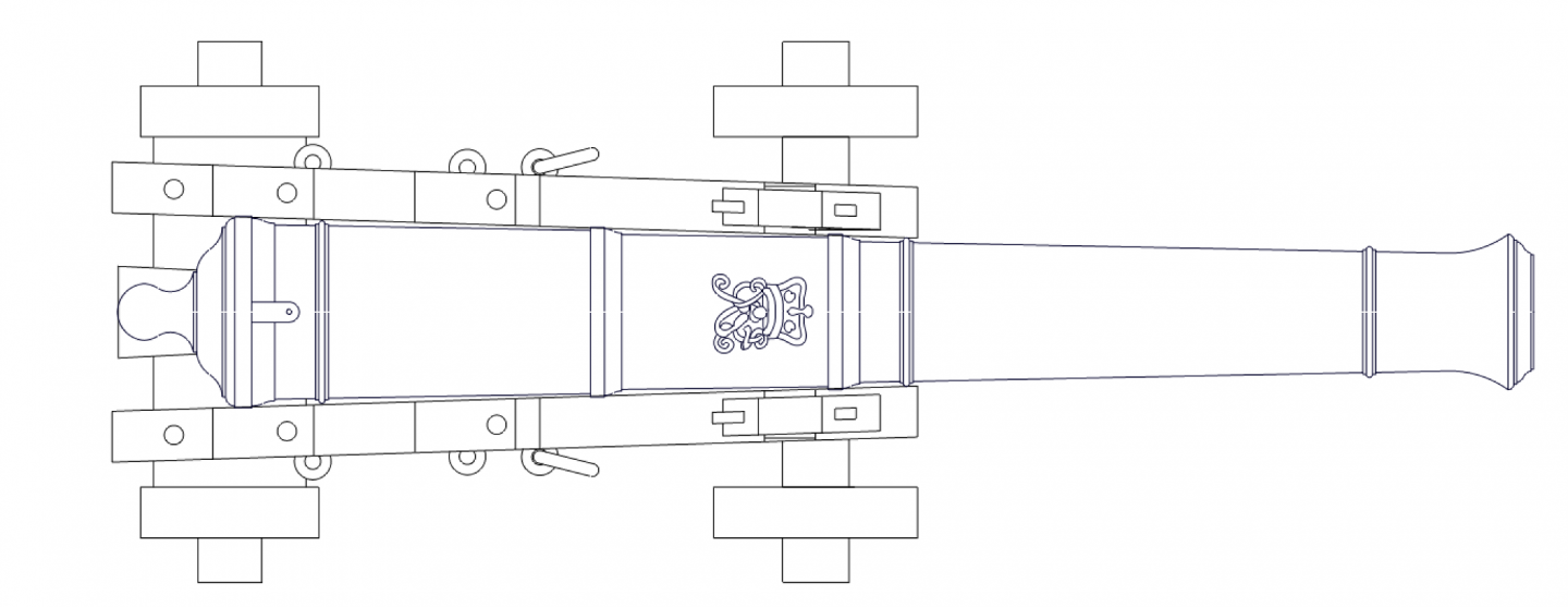
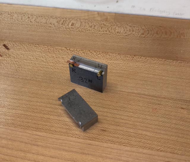
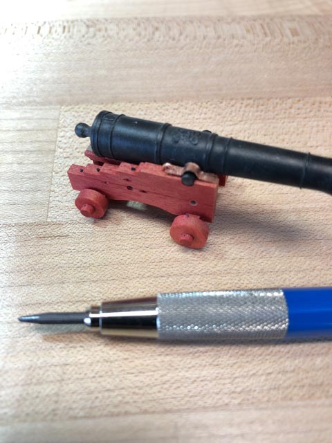
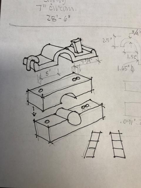
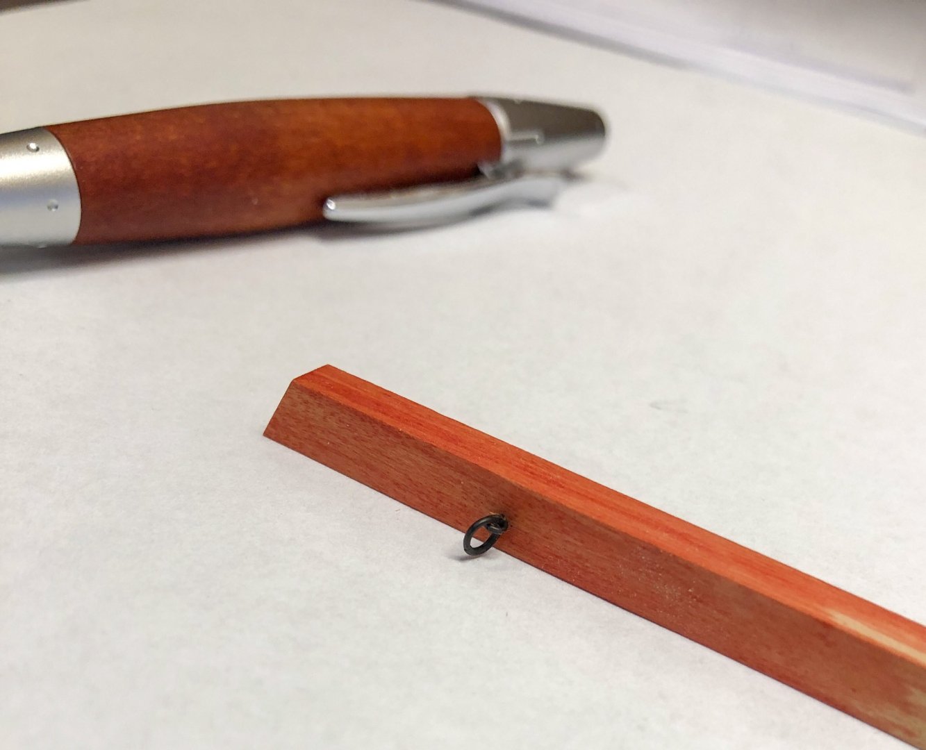
Thanks so much, JR, it sounds like you have done a great deal of research. I look forward to hearing more as you are able to give the project more attention. I might start writing down all of the issues that I don't understand yet, particularly the belaying points. Now I have confirmed that I can indeed form and blacken the iron work, I am looking ahead to another piece of ironwork that I put off dealing with until now. That is the capsquares on the gun carriages. I am still considering the possibility of installing the carriages now, but leaving the barrels off until a few years later, when I have completed more of the upper works and decks, and will be less liable to accidentally knock a cannon out of place from the outside. But that means the capsquares would have to really hinge up, so I could insert the barrel through the gun port with epoxy on the trunnions, slip them under the capsquares, and press the capsquare down in place. I made a crude mockup of a cap square, just to see how small they are, and how well I could make them hinge. Not well, I found out. the flat plate is too long, doesn't allow pivoting around the eyebolt head. So more work to do here. To make these more efficiently, I am thinking about making a small die, which would press the right shape, and then align drilling for the bolts. I know the eyebolt and joint bolt are both rectangular in section, but I am thinking this will make it exceedingly difficult to manufacture and install at this small scale. I am interested if others have managed something like this at 3/16" scale. And these are the largest cannon. It will get progressively more difficult as the guns get smaller on upper decks! Best wishes, Mark
-
Greg, thanks so much for that tutorial online. Interestingly, I started using the Otto Frei version of Sparex called OttoTech Pickle, but abandoned it when I got the flakey first effort. I turned to Acetone and then to Isopropanol before I got a good result. But I later realized that I got a good result only when I diluted the JAX, not when I changed cleaners. So I will try your various cleaning steps and see if it turns out even better. How much baking soda do you put into the neutralizing bath? Marc, I appreciate your appreciation for making it look good even when eventually we will no longer see it. I am under pressure from my wife to abandon all of the eyebolts and rings on the gundeck, because they will never be seen. But I KNOW they should be there.... I think she is worried that I won't finish before I pass on, and then how will she put my ashes on the model and push it out into the lake, maybe on fire....🙃 Mark
-
Not to make too complicated for you, I have found over the years that the Byrnes thickness sander is great for getting pieces to the right thickness, and the Byrnes disk sander for very accurately shaping joints (like the butt end of planks, corners on hatch coamings, etc). Tools can be mounted on pieces of ply or MDF, and put on shelves when not needed if space is limited. I also agree with Tony about power scrolls saws. I finally gave up on my power scroll saw as too scary on small, thin pieces; it could grab and break a blade in a heartbeat. I always had to cut pieces out of much larger sheets to have something to hang onto, and this did not allow me to use up the endless small pieces that gradually accumulate. A good jeweler's saw and bench pin (I like the ones from Knew Concepts) and a little practice, and the hand tool is much more accurate, safer and quieter. The secret I finally discovered is to get good blades, and use the right size relative to the thickness of the piece you are cutting. I use Pegas skip tooth blades, often a #3 for the sizes I am cutting. I struggled in the past when I had too fine a blade for the thickness or vice versa. Around three teeth in the wood at any time is the useful rule. The mill and lathe are great for making complex parts like the capstans, grates, steering wheel, etc. but a lot of this can be done with an accurate table saw and clever jigs, and also hand tools like files. Ah, one of the great joys of life, tools... Mark
-
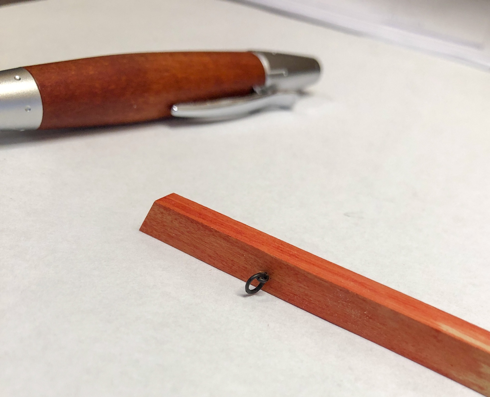
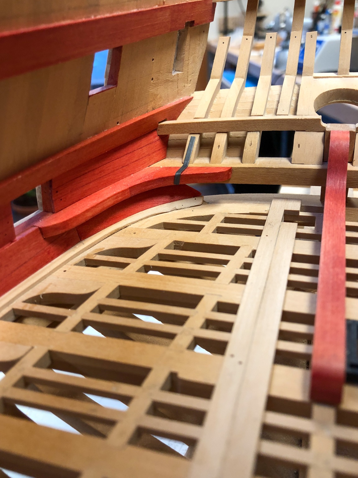
I was ready to install the gun deck standards, when I realized that I should probably put in the eyebolts and rings for the guns when I still have a little maneuvering room. I made up a few eyebolts and rings out of copper, and blackened them with JAX for copper following the instructions on the bottle. Looked great, until all the black came right off when I picked them up with needle nose pliers to push them into the holes in the quickwork. So, then I tried Ed Tosti's method in his book on the Naiad, using Liver of Sulphur which can be painted on even after the metalwork is installed in the wood. This worked, as can be seen in this sample: That means I could install the eyebolts, then blacken them in place. But then I realized that I would need to seize the breaching ropes around the rings off the model, which means that I can't then blacken the rings after installation without messing up the rope. So, I read David Antscherl's advice more carefully on blacking, in the Fully Framed Model series. He advised diluting blackening agents as much as 8:1 with water. It acts much more slowly--it took mine about 45 minutes instead of a few seconds--but it was beautifully black and stable. I tried it on a strap on the stern timbers, a beautiful sheen to the black, just like iron. So, the next test is to make up ring/eyebolts , blacken them with JAX, and assemble with a breaching rope and seizing. Then try installing and see if the black stays on. Much to learn about metal! Mark


-
Thanks so much, JR, for your kind comments, and druxey for your reminder of time scales. I wish there were as much detailed information for 1760 as there is in later books like Fincham. As I discovered in the earlier thread here on the standard at the stem, even a difference of 30 years--between 1750 and 1780--seems to make a difference. It is interesting to see trends towards bigger or smaller, and wood or iron, over these time periods. JR, I would be interested in hearing more from you about your studies on the Bellona rigging. I spent a fair amount of time years ago trying to understand this, and still do not have it completely clear in my mind. So far, I have relied primarily on the table of masts and yards lengths and diameters from a Plymouth dockyard document, 1754, in James Lees, Masting and Rigging of English Ships of War. For additional details on the masts and yards like hounds, caps, crosstrees, etc., I used Mungo Murray's Treatise on Masting, ca. 1765. I looked at data for an 80 gun ship based on the 1745 Establishment, which seemed in overall size to be about the same as a 74 gun ship ca. 1760, which is the Bellona. All other rigging information I have taken from Lees for various dates at which rigging details came into general use. I also looked to Steel for tables of rigging sizes. But Steel is a good half century later than the Bellona, and I am not sure how much changed in that period. But there are still some discrepancies and omissions in my own understanding. And while it might be a long time before I get to rigging, I have to be thinking about belaying points built into the hull somewhat sooner. I would be happy to exchange information with you about this. I have a spreadsheet linking all of my research together. Best wishes, Mark
-
Thanks so much, JR, for your kind comments and also the additional information from Fincham. I would be interested in hearing more from you about your studies on the Bellona rigging. I spent a fair amount of time years ago trying to understand this, and still do not have it completely clear in my mind. So far, I have relied primarily on the table of masts and yards lengths and diameters from a Plymouth dockyard document, 1754, in James Lees, Masting and Rigging of English Ships of War. For additional details on the masts and yards like hounds, caps, crosstrees, etc., I used Mungo Murray's Treatise on Masting, ca. 1765. I looked at his data for an 80 gun ship based on the 1745 Establishment, which seemed in overall size to be about the same as a 74 gun ship ca. 1760, which is the Bellona. All other rigging information I have taken from Lees for various dates at which rigging details came into general use. I also looked to Steel for tables of rigging sizes. But Steel is a good half century later than the Bellona, and I am not sure how much changed in that period. But there are still some discrepancies and omissions in my own understanding, which I will have to recall from my notes at this point. While it might be a long time before I get to rigging, I have to be thinking about belaying points built into the hull somewhat sooner. I would be happy to exchange information with you about this. I have a spreadsheet linking all of my research together. Best wishes, Mark
-
Lovely ovens, Gaetan. How did you make the orange colored bricks? Interesting that the French had more cooking facilities than the English for the same size ship. The distinguished French culinary tradition started a long time ago! Mark
-
DIY Dremel Table Saw/Router Table
SJSoane replied to Julie Mo's topic in Modeling tools and Workshop Equipment
I have been thinking about making a router table, and just came across this post. Nice solution! what size sanding sleeve hits the side of the Stewart/MacDonald mounting base? Could they be gripped further out of the chuck, getting to the other side of the mounting base plate altogether? Mark -
I haven't tried softwood in the Byrnes machine, but I have worked out good results with hardwood. (I am left handed, so this might want to be reversed for right handers). The trick is to keep the wood moving constantly while holding down flat on the infeed and outfeed at all times. I start by pushing constantly with the thumb of my left hand while using my right hand to press down firmly on the infeed table, fingers very close to the opening. As the wood approaches the end of the infeed table, I reach back with the thumb of my right hand to keep the wood moving forward and still pressing down. My left hand is then free to move to the outfeed table, where I pick up the forward movement and downward pressure by placing my fingers under the table and my thumb on top of the wood, squeezing the wood to the table while also pushing forward with my thumb on the top surface. When my right hand can no longer push the wood, I move it to the outfeed table and do the same thing, squeezing the wood to the table while pressing forward. I alternate pushing with left and right thumbs, so I never have to pause the forward movement while moving a thumb back. Pausing the forward movement even for an instant will leave a ripple in the final surface. I can get sore thumbs doing this with a lot of sanding! With longer pieces, if I move the wood too quickly, or let up on the squeezing even by a tiny amount, I can get an harmonic vibration of the wood on the outfeed table, causing a very slight rippled surface on the wood. So press down for dear life, and slow down if you get this problem. Another option, if this doesn't work for you, is perhaps to make a long sled with a stop somewhere in the middle. As you push the sled and the wood through, the back of the sled will still be on the infeed table while the wood is already passed through the drum. It give a greater chance to keep things pressed down and moving constantly forward until the wood is further through. I haven't tried this with a long sled, but my short sled makes it very easy to pass shorter pieces through without problems. I hold the wood down onto the sled with double sided tape in the case of short pieces. Maybe this would help with longer ones as well. Just some thoughts! Mark
-
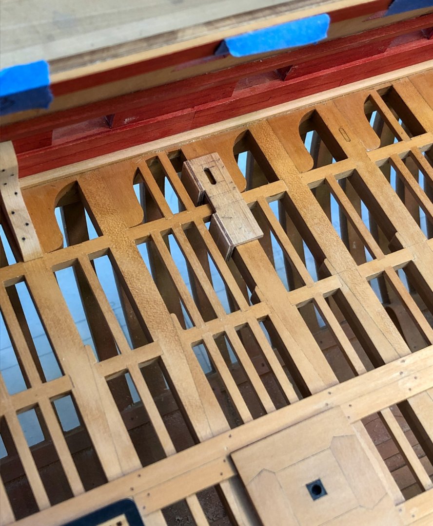
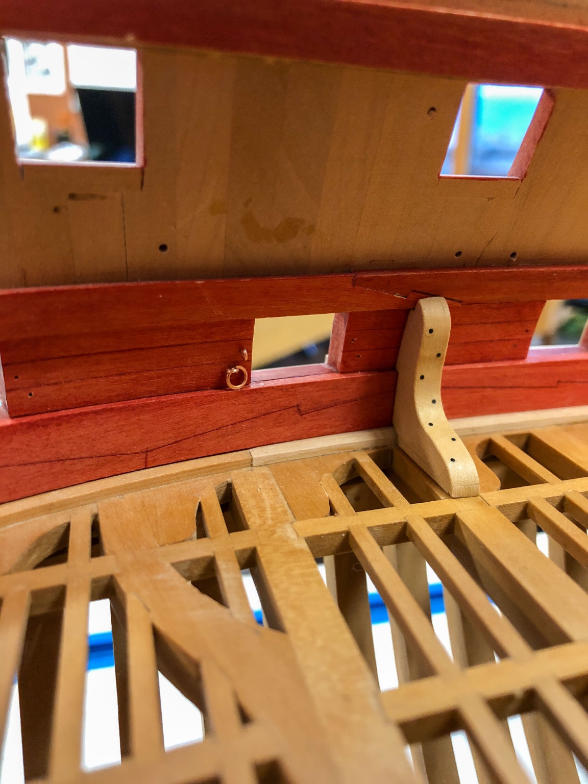
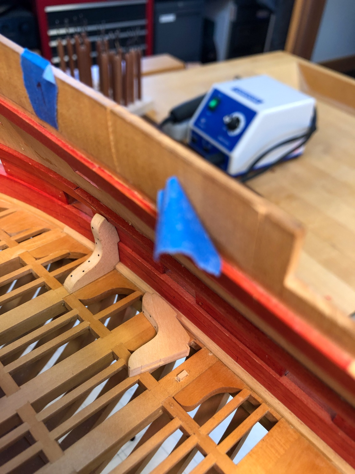
Thanks so much, druxey, and a better new year for all of us! I proceeded with the spline idea. A little jig for the mill made quick work of the slots in the standards themselves: For the slots in the deck beams, I made a little marking jig, ensuring the slots would be laid out parallel to the sides of the beam, on the center line, and also the correct distance from the end of the standard. Then a few holed drilled out to hog out the main waste, and then chisel work to clean up. I did discover a slight flaw in my plan. If I made the splines as long as I had expected, the standard could not fit over the spline and then slide under the upper deck clamp. So I had to shorten the splines and keep them as far out from the sides as possible. This allows me to fit the standard down on the spline, and then slide into position while completely flat on the beam. But still more than enough area for gluing. Three down, just 19 to go.... Mark