schooner
-
Posts
741 -
Joined
-
Last visited
Content Type
Profiles
Forums
Gallery
Events
Everything posted by schooner
-
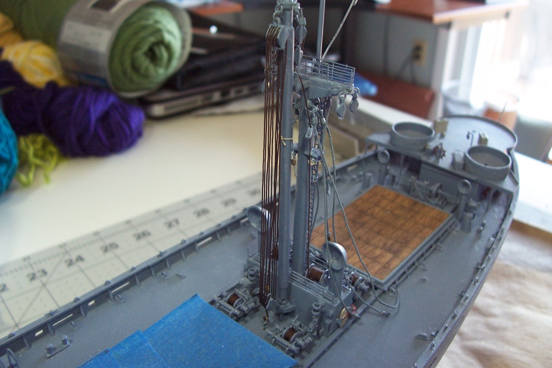
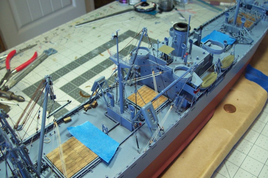
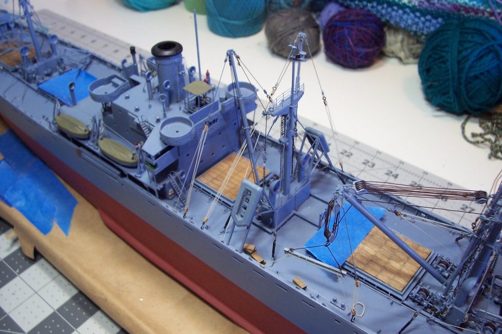
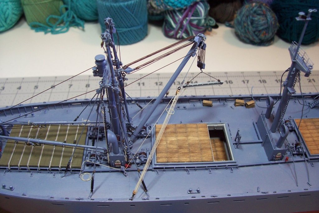
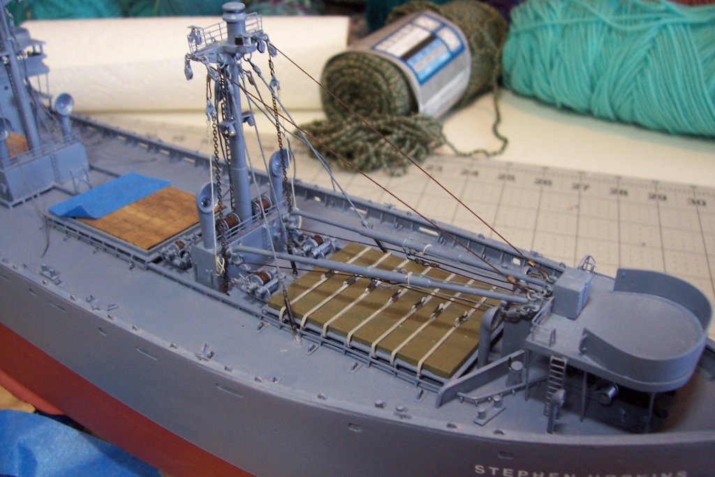
 Final Cargo Rigging The booms on Hatch nr5 are configured in what was known as a “Wing and Wing’ rig, another variation on the Yard and Stay rig used on hatches 3 & 4. The Wing & Wing had the ends of both booms over the side of the ship, allowing cargo to be worked on both sides simultaneously. One feature of it is that the are no inboard guys - the ends of the booms are just lashed together for support. I still have to trim some tag end and add some rope coils. Next up will be the lifelines and PE railings.
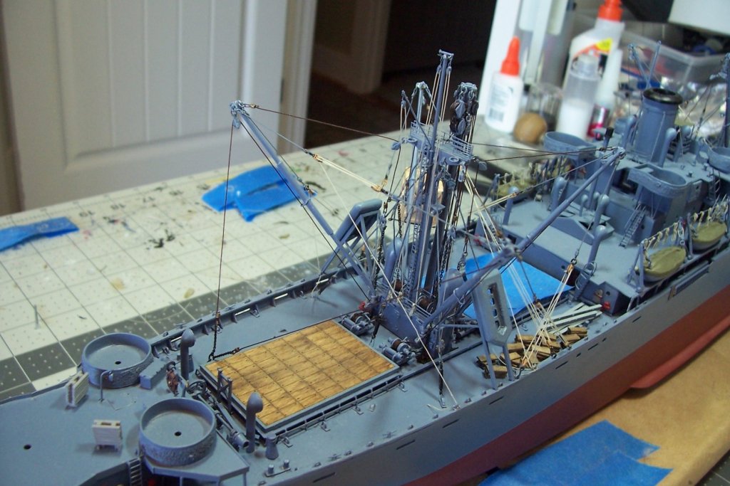

- 227 replies
-
- 10
-

-
- BlueJacket Shipcrafters
- Stephen Hopkins
- (and 2 more)
-
Thanks for the link Nic. Just out of curiosity, is BlueJacket looking at using 3-D printing for any parts? I know the upfront costs can be eye-watering.
-
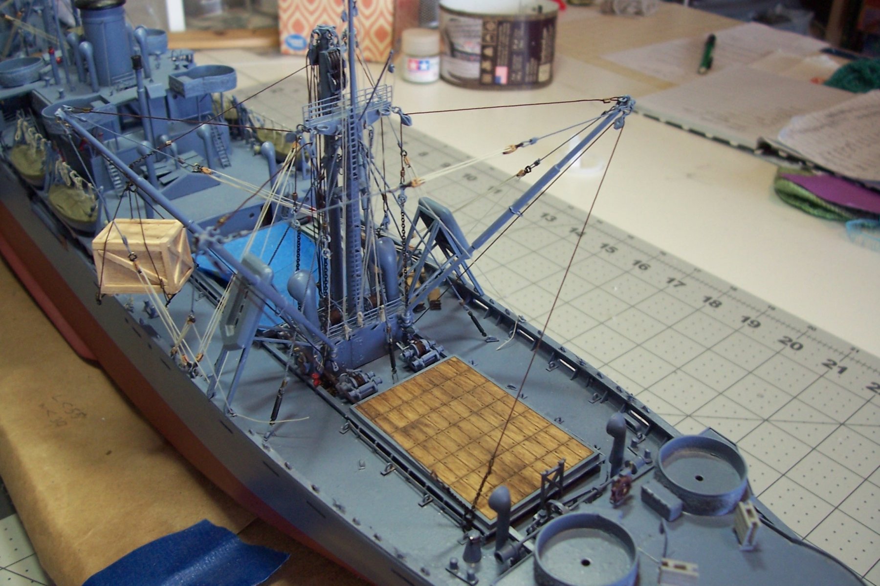
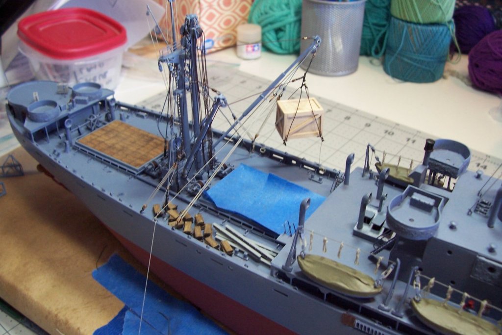
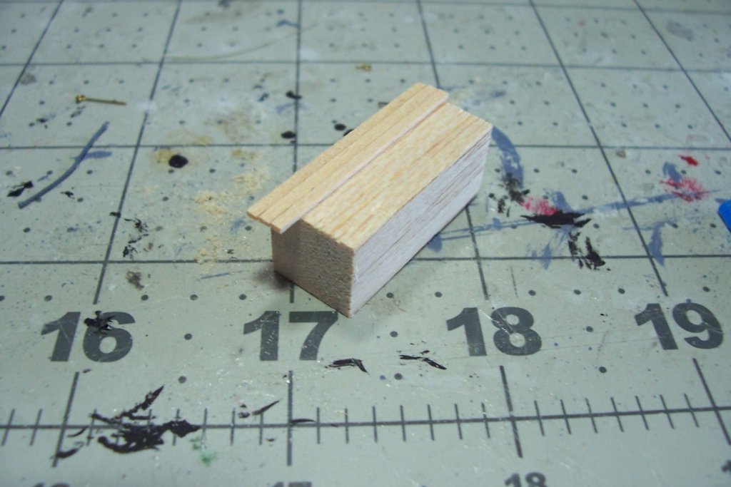
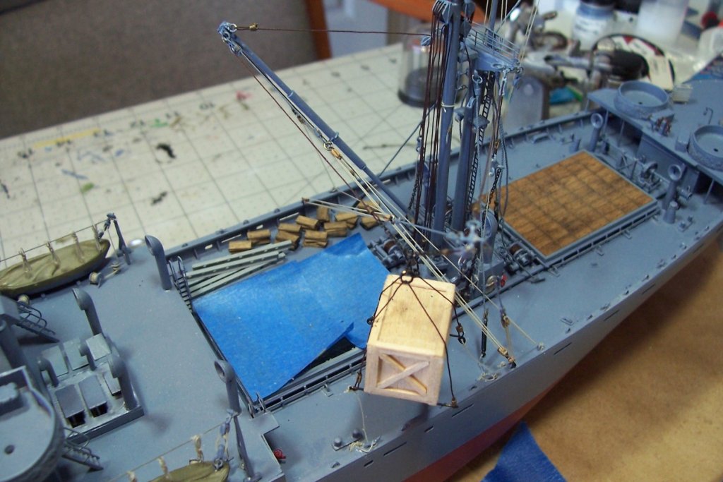
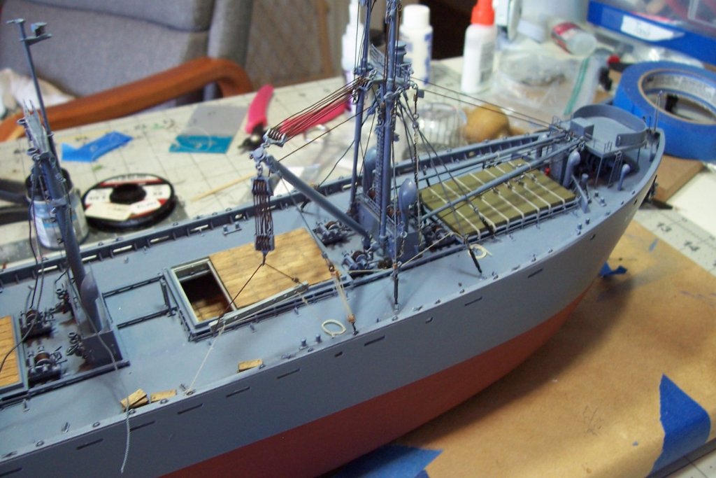
Rigging Hatch Nr 4 I lost a few weeks of work when I did not pay attention to my supply bin and ran out of rigging thread. It has finally come in so I can press on. This hatch, like Nr2, also has a jumbo boom (30 ton vice 50 ton) which I decided to rig in the vertical stowed position: Since Nr4 hatch will be the only completely “open” hatch on this build I wanted to show a suspended load above it. I thought it would be quick and easy to find a truck or bulldozer online but it ends up that 1/192 (1/16 inch) scale is not used for model railroading and there is really nothing out there near this scale that I could use so I decided to whip up a large crate. After numerous attempts and a lot of bad language I was about to give up because I could not get all the corners square, then I had a DUH! moment and realized I did not need to build a 6-sided box - I could just get a piece of rectangular stock of the right width and height, cut it to length and “plank” it which ended up being very simple to do: This boom arrangement is a variation Yard and Stay rig used on hatch Nr3, this one being called the West Coast Rig. It is supposed to work faster but I’m not sure why. Since this hatch is completely open I arranged the removed hatch covers and hatch beams along the unengaged side: Just one more hatch to go and this build is almost done:

- 227 replies
-
- 7
-
-
- BlueJacket Shipcrafters
- Stephen Hopkins
- (and 2 more)
-
wonderful scratch building - love the engine room!
-
Greg, just got thru with the first page of this build only to find you already have 10 pages posted! Its amazing how much ground you cover in just 3 months. Interesting choice for a build. I've read a ton of naval history but never gave this ship much attention since she was never completed. I had no idea she was so big, I just assumed as Germany's first carrier that they would have started off with something small to learn the tricks of naval aviation. Guess they must have thought "Ach, how hard can it be?" Given Germany's huge problems with inter service squabbling its interesting to think what problems they would have run into if she had become operational. I'm sure they would have made the RN's problems with RAF control of carrier plane design and acquisition seem minor by comparison. Your scratch building and weathering are, as always, the top of the game. Now, back to page 2 of your build!
- 345 replies
-
- 5
-
-
- graf zeppelin
- trumpeter
- (and 2 more)
-
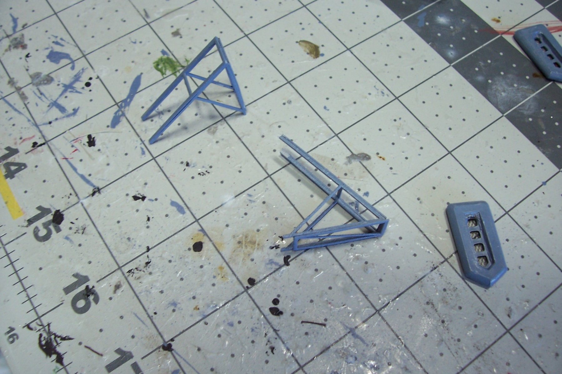
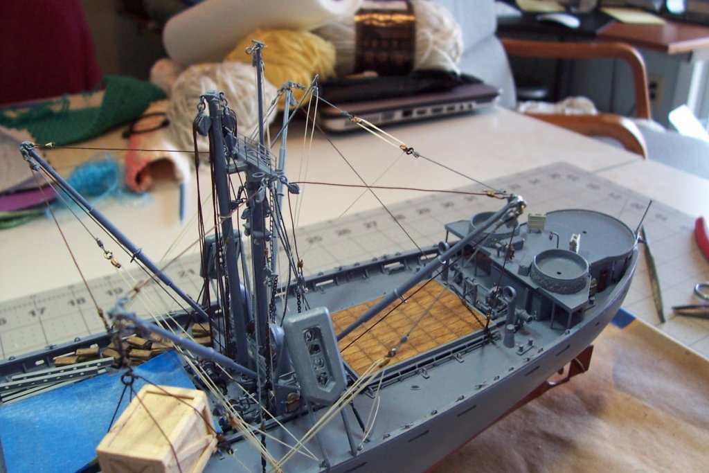
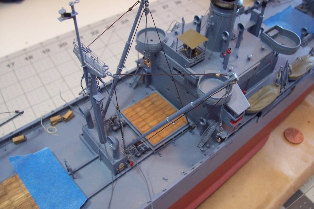
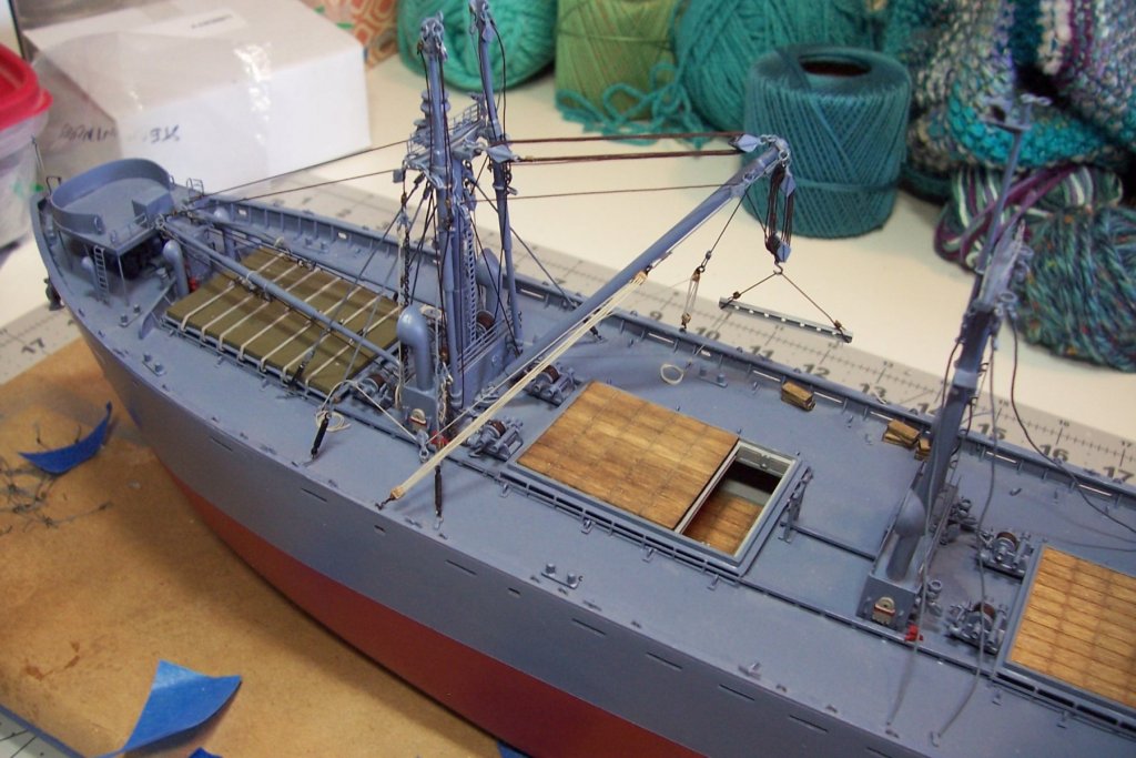
Hatch Nr3 Rigging This hatch, like the last 2 to still to come, is rigged as a “Burton” or “Yard and Stay,” rig which had several variations. This hatch is rigged as the “standard” type. What made these rigs interesting for me is that the booms do not move during the cargo operation; the cargo can be moved anywhere along a line connecting the 2 points directly under the end of each boom by coordinating the 2 cargo winches. In this case one boom is positioned directly over the center of the hatch and the other over the side of the ship for loading to/from a pier or lighter. When I was onboard the SS John Brown in Baltimore they ran a demonstration of a yard and stay rig at work, pretty simple when you see it in operation but it took a lot of concentration by the winch operators and foreman, one missed signal and the winches could end up pulling against each other which would quickly collapse the whole rig, with all the expected death and destruction. Here the 2 cargo whips are rigged together and secured to an eye pad near the hatch: I had to install the life raft racks before rigging the guys to make sure there would be no interference. The racks are made up of 4 pieces of VERY thin laser cut wood. It was a little intimidating cutting them loose from their fret/billet but once they were glued up they are pretty sturdy: Here is the final rigging, minus rope coils that will come later - it is starting to look pretty busy:
- 227 replies
-
- 18
-
-
- BlueJacket Shipcrafters
- Stephen Hopkins
- (and 2 more)
-
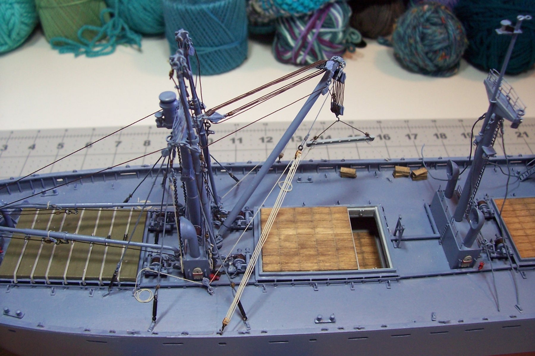
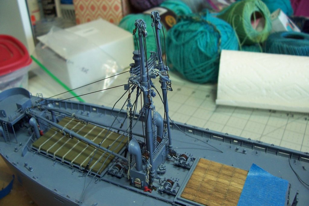
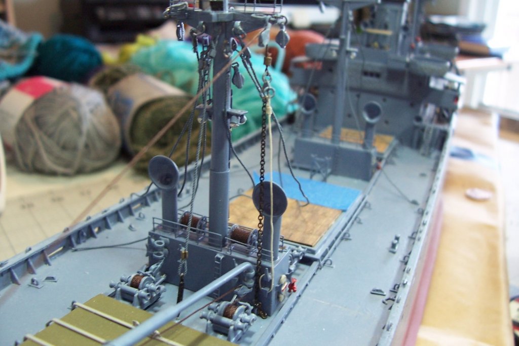
Rigging Hatch Nr2 and the 50-ton Jumbo Boom The first step was to rig the 2 5-ton booms in the vertical stowed position: Then the fun started. I usually enjoy rigging blocks because they look good on a model. Up to now a triple block has been the most ambitious for me but this called for 4 quintuple blocks and having to adjust the tension between 20 running lines on the blocks tried my patience. I came to realize that I had to be able to tension the rig after the blocks were set so I decided to use the 1 hatch beam and show it suspended as if it had just been hoisted off the hatch and about to be stowed on deck near the hatch covers that had already been removed. Doing so allowed me to use the 2 tag lines from the bottom of the beam to tension the whole rig. Once the boom vangs were rigged I was able to attach the shrouds on the foremast so everything is good to go. The 2 jumbo booms were the only ones that pivoted on their base like a normal crane - the 5-ton booms were fixed in place. In order to swing such a large boom the vangs had to be taken to power using the capstans on the 2 winches on the adjacent hatch so using a jumbo boom required 4 winches and prevented the adjacent hatch from being worked at the same time. Doing this part of the build showed me what a huge job it was on these ships to shift between the 5-ton booms and the jumbo booms or vice versa. As shown now, to go back to using the 5-ton booms their cargo whips would have to be unwound from the storage reels on top of the mast house and laid out on deck. Then the Jumbo boom cargo whip and topping lift wires would have to be removed from the winches on Nr2 hatch, wound onto the storage reels, and then the 5-ton cargo whips wound onto the winches. It is hard to imagine a more dirty, difficult and dangerous job than wrestling with so much thick wire rope, all of it covered in thick slushing grease and full of needle sharp broken wire strands and fish hooks. Tough, tough guys.
- 227 replies
-
- 16
-
-
- BlueJacket Shipcrafters
- Stephen Hopkins
- (and 2 more)
-
Thanks Nic, Although they turned out alright they involved some very Easter-inappropriate language! Glad I had some spares to fix individual letters.
- 227 replies
-
- 3
-
-
- BlueJacket Shipcrafters
- Stephen Hopkins
- (and 2 more)
-
Wonderful work, very crisp and clean. The Willie B is my all time favorite kit, one of the few available that allows you to build a model that is 100% authentic, and is built in the same sequence as the original. Making the winding frames and railings was a grad course in soldering and metal work for me - learned a lot. Keep the pix coming
-
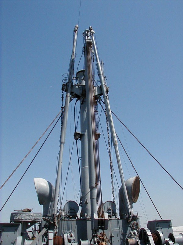
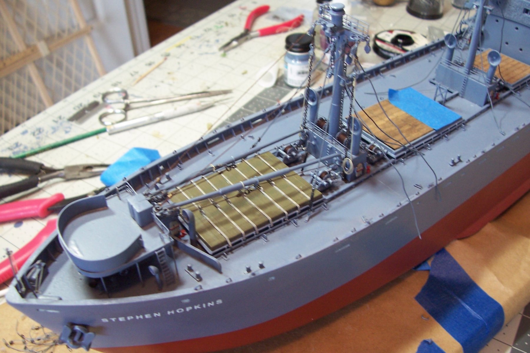
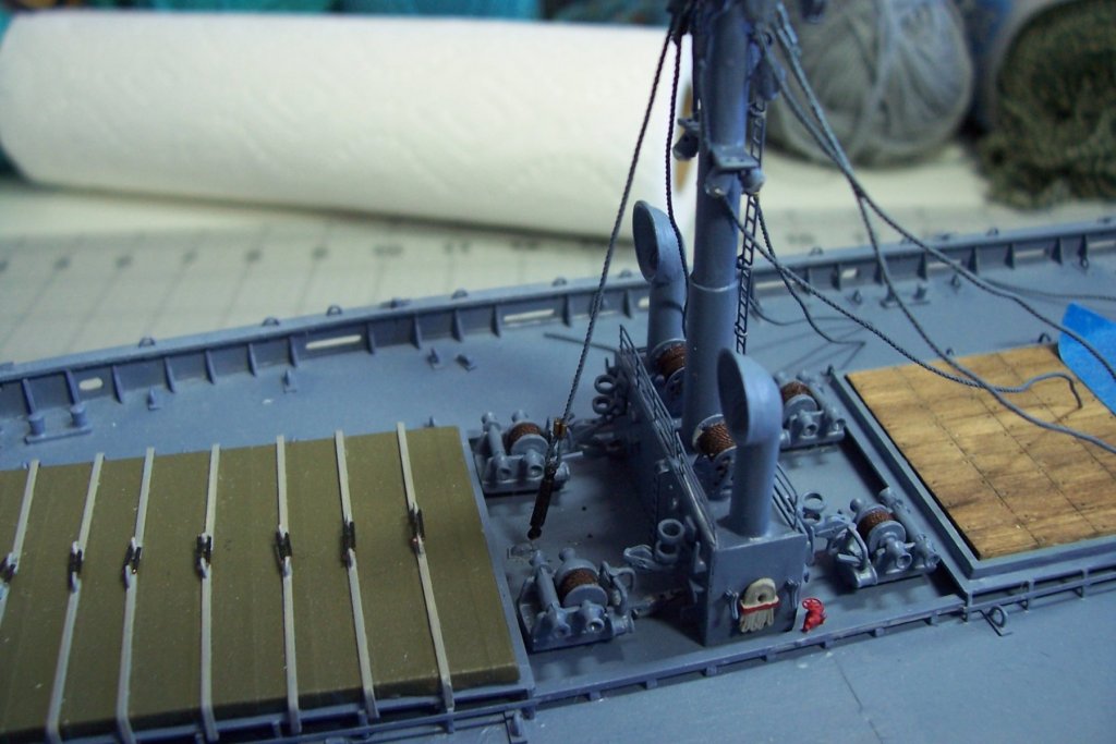
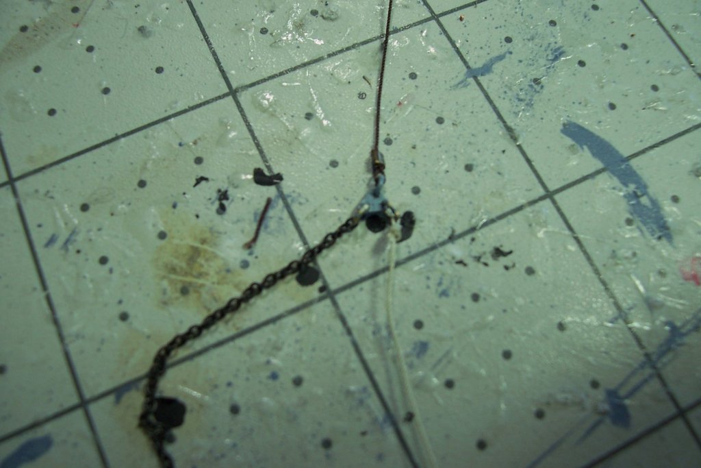
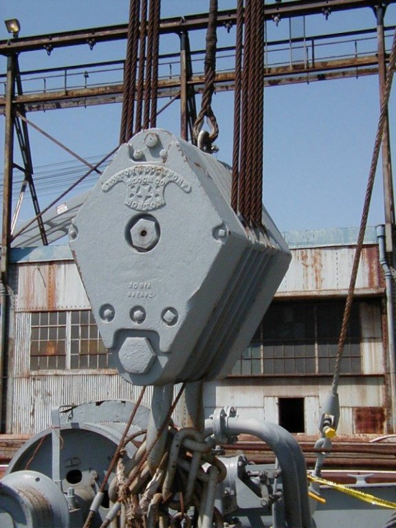
Rigging Cargo Booms - Hatch Nr 1 Well it’s finally time to start rigging this pig. I’m going to start with Hatch Nr1, which since it will be shown secured for sea it will be the easiest. The forestay for the foremast goes on first. I thought it would be some simple work with tweezers to attach the upper end but I ended up using needle nose pliers and tweezers from a lot of angles so I decided to attach the upper ends of all the shrouds and stays now while the area is free of other rigging so there is some spaghetti hanging from all the masts: The 2 5-ton booms where rigged up next. Since the booms will be in the stowed position the blocks normally used on the vangs have been left off and the wire rope pendants are just lashed to the booms. On my first post for this log I mentioned that one of the things that caught my attention about Liberty Ships was the use of large chains on the masts: I came to learn that they are call “bull chains” and they are a clever solution to a problem. The topping lift on a boom is used to raise and lower the outer end of the boom and it also supports the boom and whatever load is is lifting so they are made of wire rope for strength. The topping lift is taken to power on one of the capstan heads on the boom’s winch. The problem comes in that you can’t wrap wire rope around a capstan because it won’t “grip” it and you can’t have manila rope as part of the lift because it is too weak to support lifting a cargo load. They solved the problem by having the end of the wire topping lift attach to the top of a triangular plate, the bottom of the plate was connected to both a length of manila rope and a length of chain. The rope was wrapped around a capstan head and taken to power. When the topping lift was in the desired position, the chain next to it was shackled to the deck using whatever chain link was closest to the deck eye, the rope was then slacked off and the weight of the boom and load was now carried by the wire rope connected to the chain. By having a long length of chain they could position the boom anywhere from horizontal to vertical and still have a strong topping lift. Pretty neat. They could get away with this because these booms were fixed in position and were not swung or raised or lowered while in use (I’ll explain how that worked when I rig one of the “working” hatches). Here’s the topping lift/bull chain in place: And here is the completed hatch after some touch-up painting. The booms are shown stowed in the horizontal position. If there was over size cargo stowed on to of the hatch, like a tank, crated aircraft, PT Boat, etc then the booms would be stowed in the vertical position when at sea. The 2 additional fore stays where only rigged when the Jumbo Boom on the aft side of this mast was in use, it will be on this build hence the stays are rigged. Although they partially block the hatch opening it wasn't an issue because all the winches for both Nr1 and Nr2 hatches all had to be used to work the Jumbo Boom which I will show when I get to Nr2 hatch: 1 hatch down, 4 to go.


- 227 replies
-
- 9
-
-
- BlueJacket Shipcrafters
- Stephen Hopkins
- (and 2 more)
-
Just caught on to your build, fantastic as always. I thought the Orange Hobby PE sets were tough but this one takes the cake, it is one thing to lose PE parts into the carpet but to lose them into the folds of your fingerprints!
-
Thanks for the feedback Carl and Lou.
- 227 replies
-
- 2
-
-
- BlueJacket Shipcrafters
- Stephen Hopkins
- (and 2 more)
-
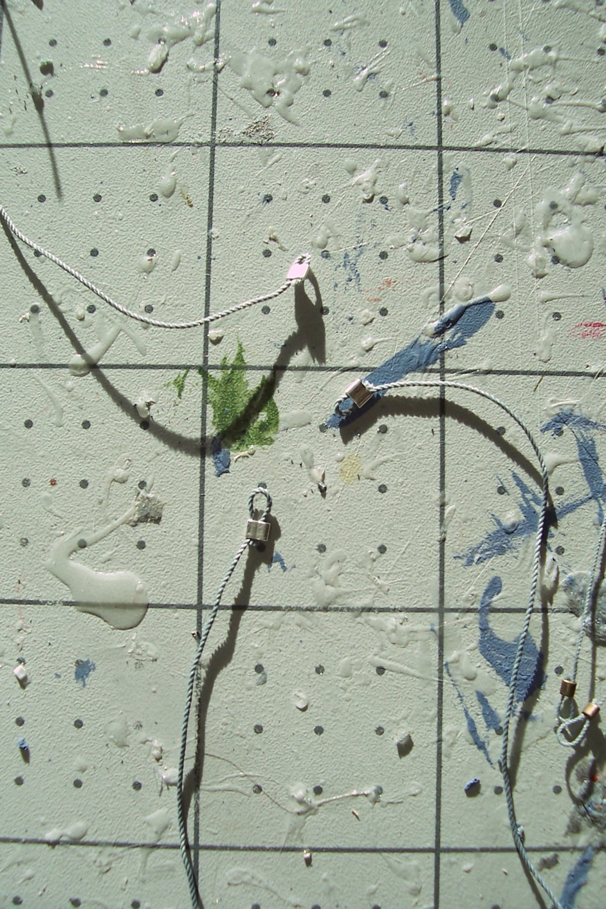
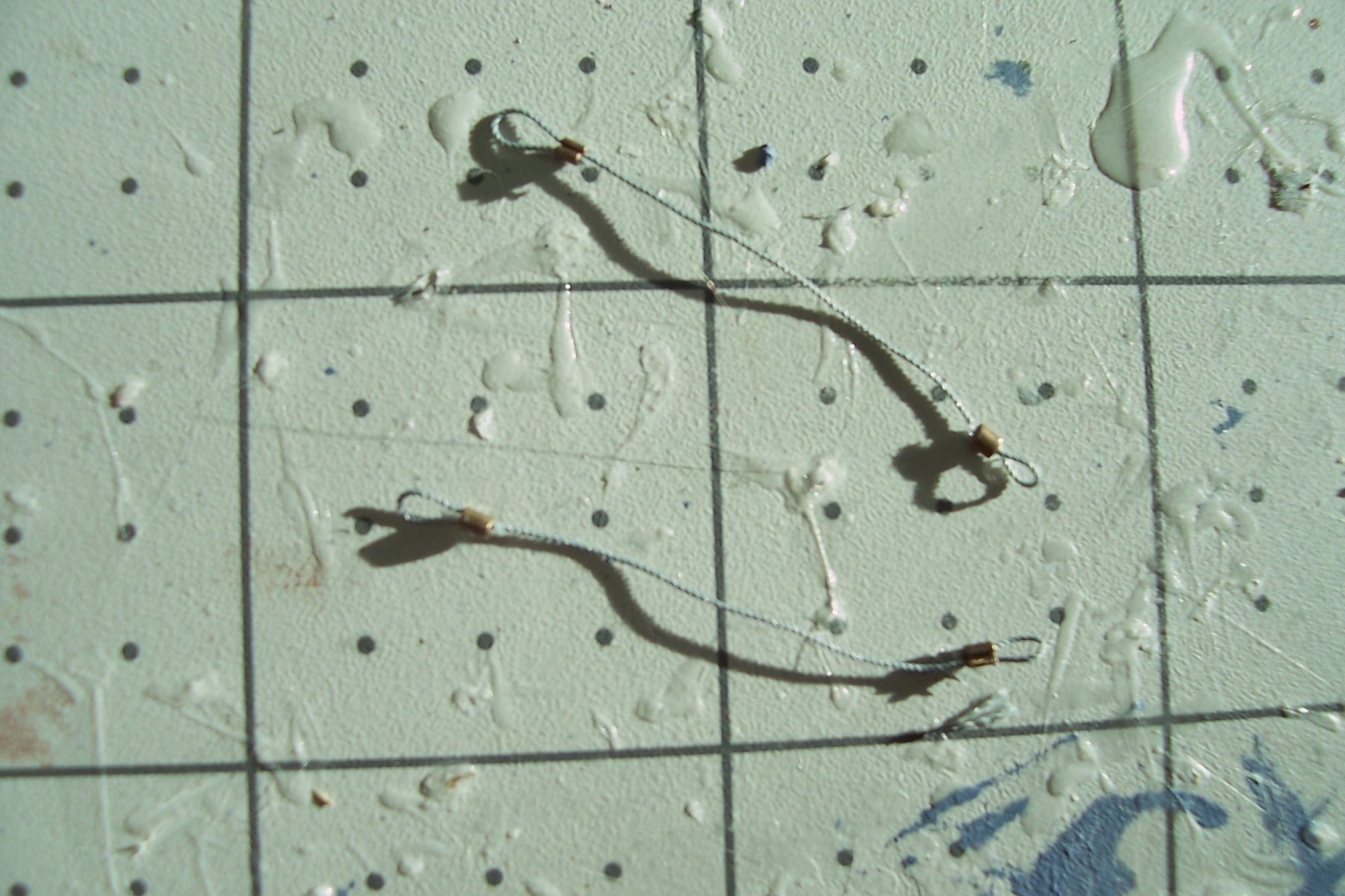
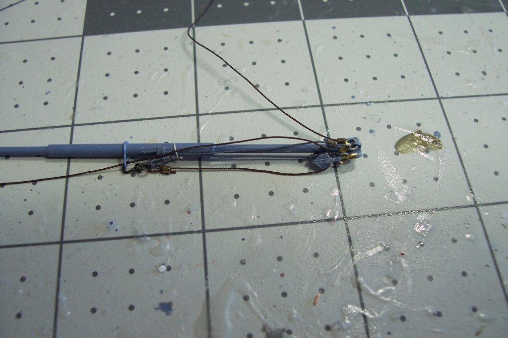
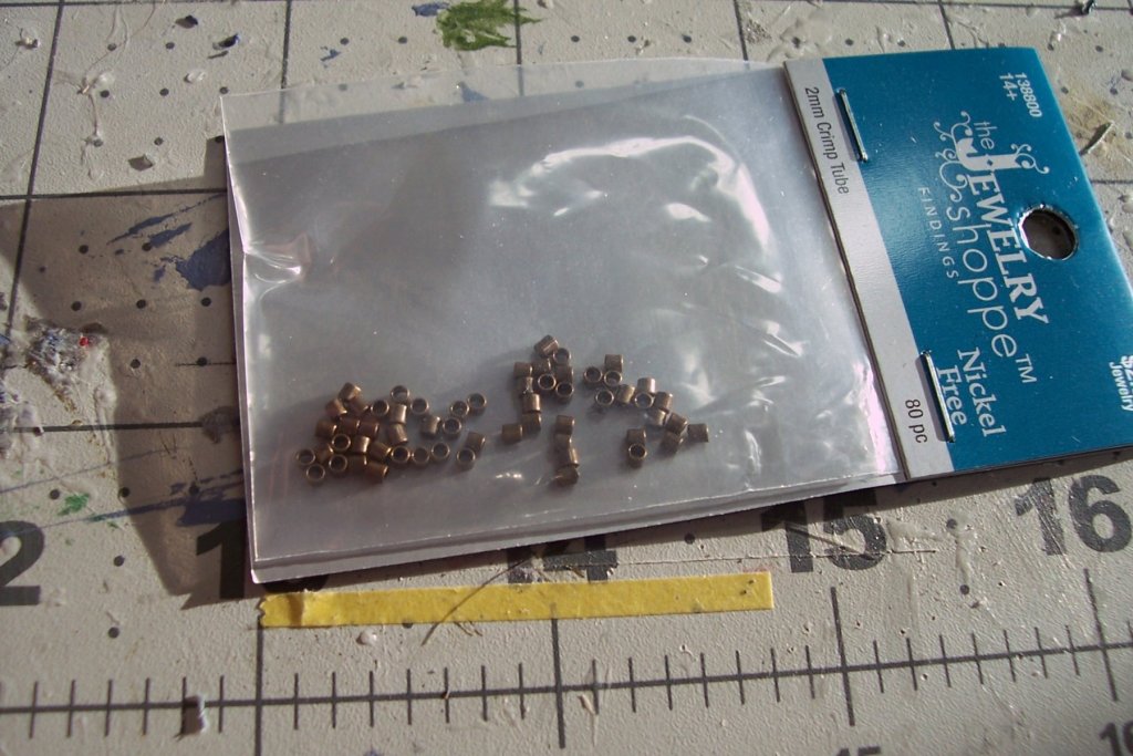
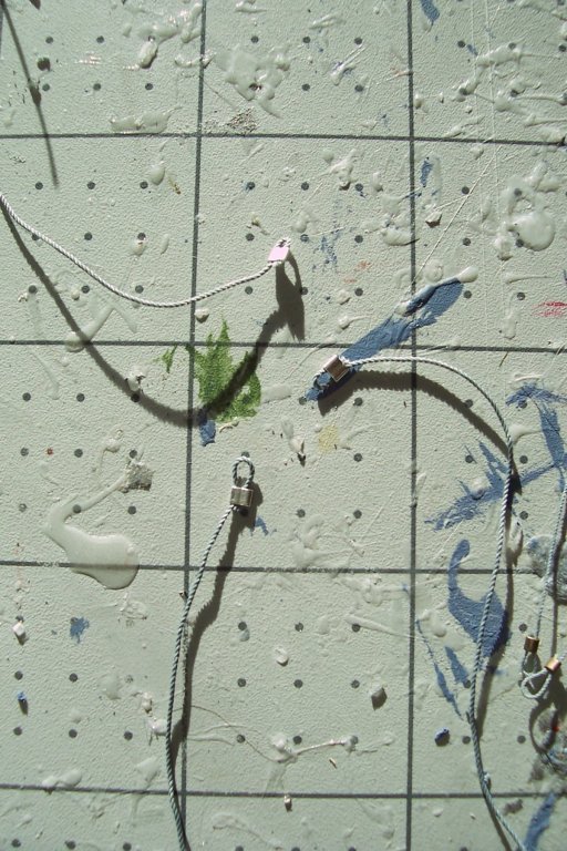
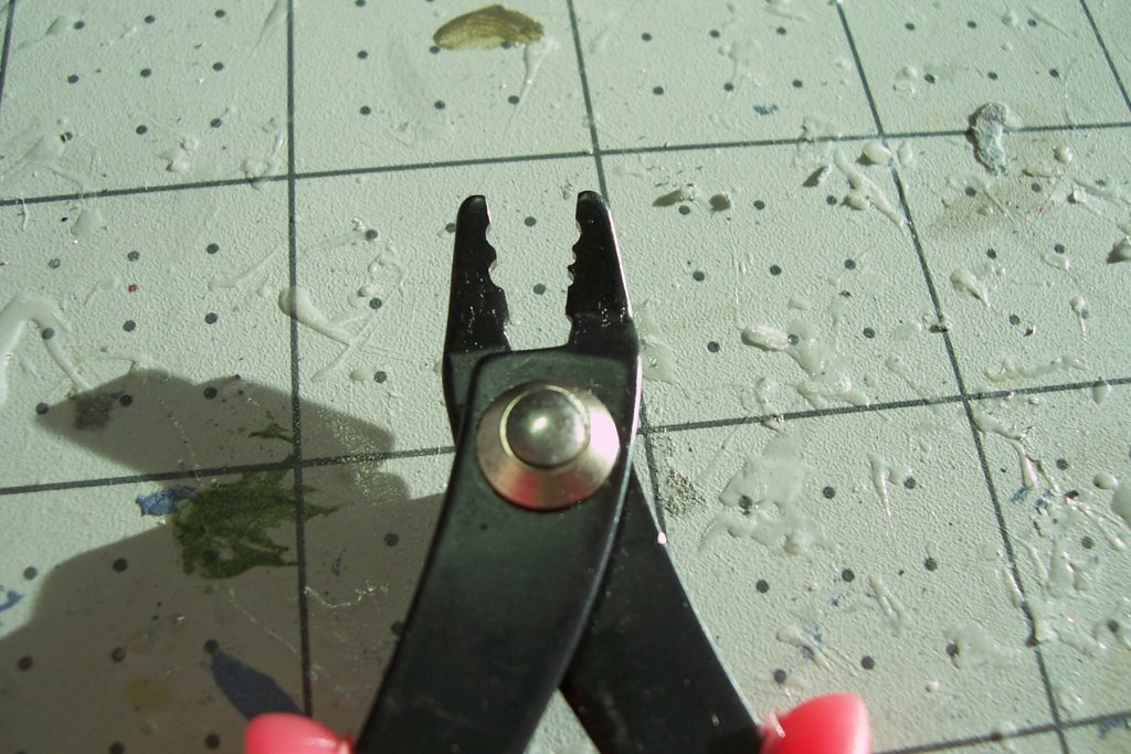
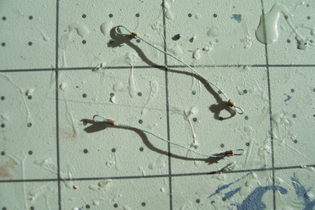
I wish I knew about this earlier…. I’ve been spend the last week or so getting ready for the last big job on this build - rigging the cargo booms. I’ve been fabricating cargo hooks, drilling out and painting britannia blocks and doing what seizing I can off the model. About 50% of the rigging will represent manila line which I will tie off with seizing wherever possible. The other half will be representing wire rope, both greased (slushed) and painted. I’ve been mulling over is how to tie-off the wire rope. Knots would look pretty bad and seizing, while better, is still not realistic since wire rope was not seized - the eyes are either secured with poured sockets or clamps. I didn’t think I could pull it off with just glue but then I saw something on Mahuna’s amazing build log for the skipjack Kathryn here on MSW, he used crimping tubes to secure some of his rigging. Crimping tubes are used in jewelry making and, lo and behold, my wife happened to have some on hand: When I squeezed them with needle nose pliers they secured the eye in the line OK but they were inconsistent in how the lines led into them and were too flat and broad for my eye. After poking around on that great repository of knowledge, YouTube, I found the trick is to use crimping pliers. The pliers use a 2-step process, the first flattens the tube but also leave a crease down the center of it, in the second step the tube is moved to another spot on the pliers and the tube is folded over the crease leaving a nice, tight and consistent seizing that is realistic for wire rope: These might be useful for anyone wanting to secure rigging that represents wire rope, radio antennas or even “rope” where there is not enough room to put on a seizing.
- 227 replies
-
- 10
-
-
- BlueJacket Shipcrafters
- Stephen Hopkins
- (and 2 more)
-
Amazing job Greg! I've always shied away from trying to weather my models because I've seen so many otherwise great builds ruined by a heavy hand but you have an excellent sense of what will work - your models are the most realistic I've seen. You ought to see if the film industry is hiring for special effects model making! It was a pleasure to watch this take shape. Tim
-
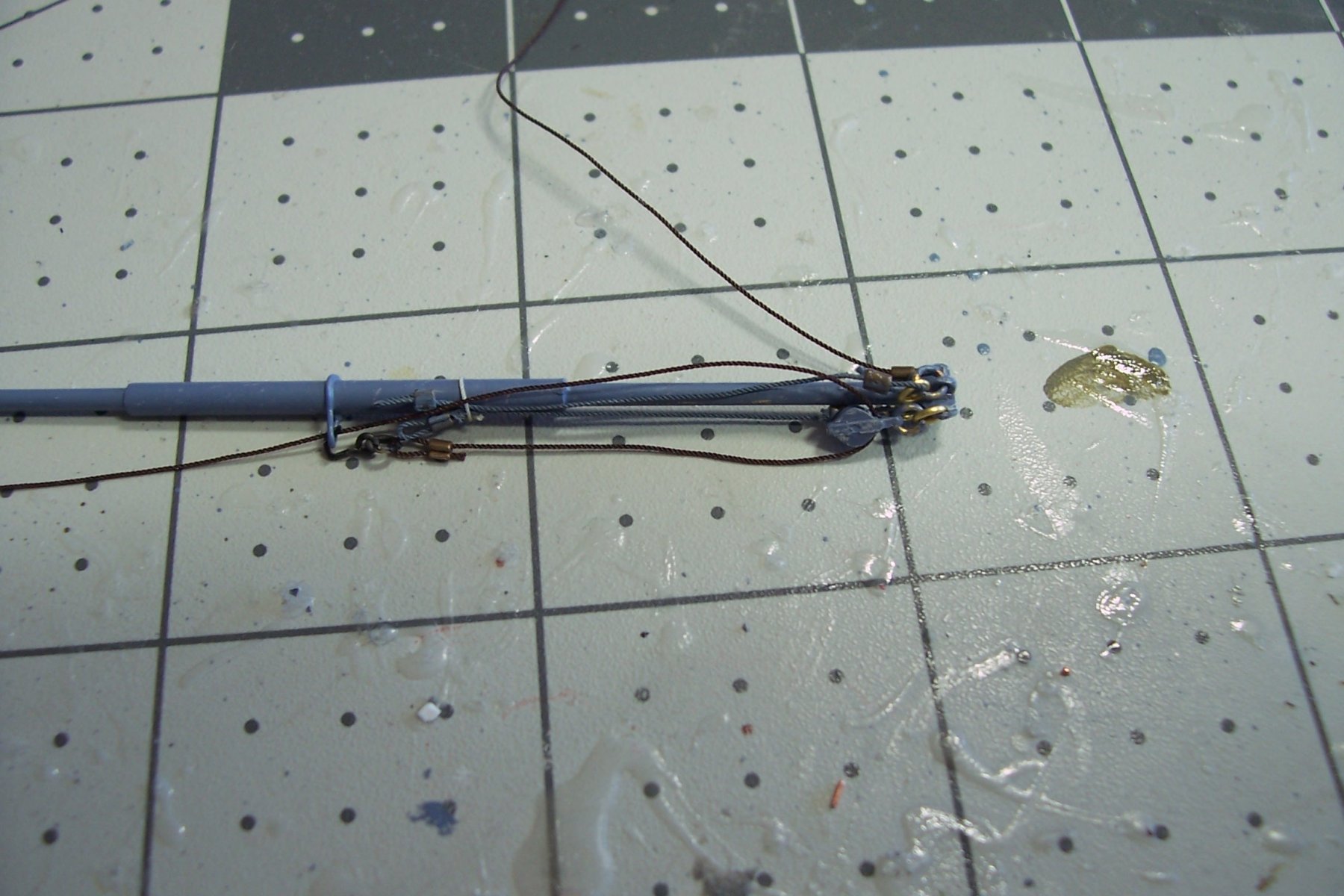
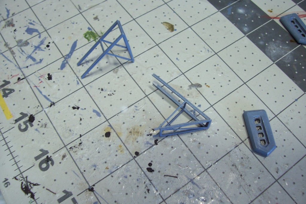
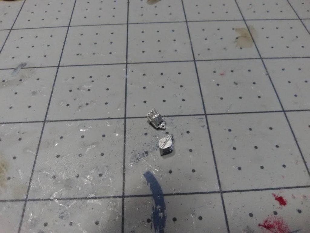
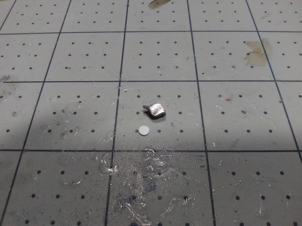
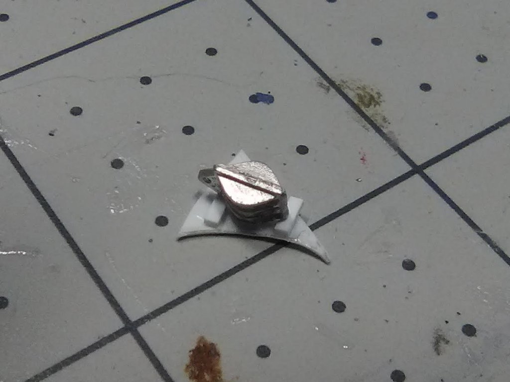
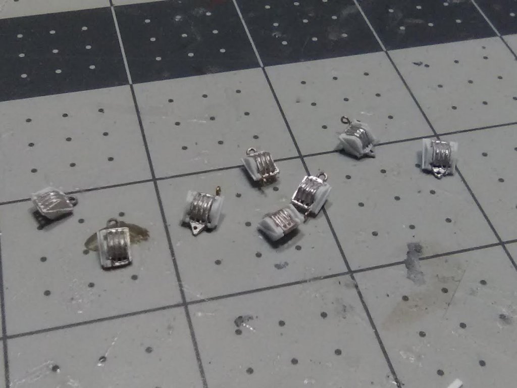
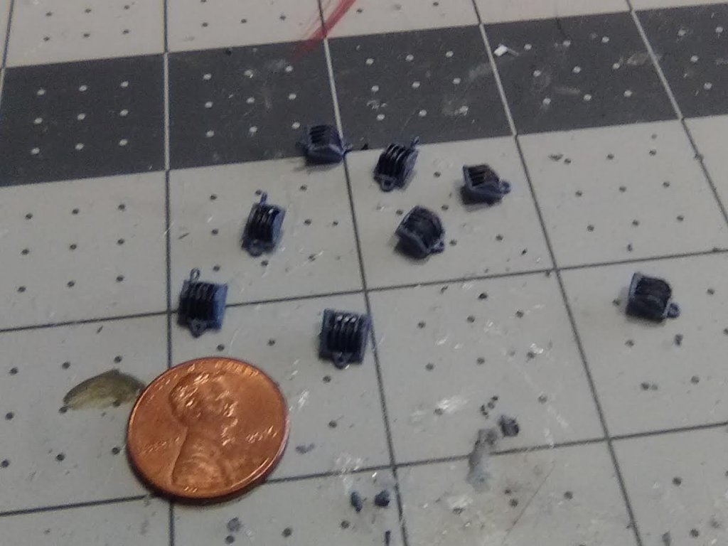
Jumbo Boom Blocks One of the details I had to finish up before starting the rigging was the 30 and 50-ton “Jumbo” booms. Unlike the 5-ton booms which got their lifting power straight off of the winch, the booms used for lifting heavy loads like tanks and planes needed the extra lifting power provided by large pulleys, 5-sheave for 50-ton, and 4-sheave for the 30-ton. They were some big honkers - almost 6 feet high including the cargo hook: Fortunately Bluejacket sells some 1/4 inch blocks that are exactly what I needed for shape, height and length: The only problem is that they are triple blocks so I needed to modify them to get them right for this build. I started by sanding off the stropping on one side for the 4-holers and both sides for the 5-holers. Then I used my punch set to make sheave discs from sheet plastic of the right thickness: After gluing on the discs I covered them with oversized sheet plastic: The plastic was then trimmed and sanded to match the original shape. The 4-holers needed to have the lifting eye cut off and new ones added to the “new” centerline, all of them had new stropping to replace what was removed, and half of them had beckets added (the starting point for rigging a set of blocks): After painting these should do the trick:

- 227 replies
-
- 7
-
-
- BlueJacket Shipcrafters
- Stephen Hopkins
- (and 2 more)
-
With a stack like that I bet she rolled even at the pier!
- 227 replies
-
- 2
-
-
- BlueJacket Shipcrafters
- Stephen Hopkins
- (and 2 more)
-
Thanks for all the info Lou, especially for the 50 cal photos - I wish I had found those. I suspected the #3 photo was on a 4-piper but the Royal Navy cap on the sailor threw me until I recalled the destroyers for bases deal in 1940 or 41. This photo must have been taken when the RN crew was taking one of the ships out for shakedown right after the transfer because the RN heavily modified those ships as soon as they could to better suit them as convoy escorts and I'm sure the 50 cals were craned off right after the 4 torpedo tubes mounts!
- 227 replies
-
- 3
-
-
- BlueJacket Shipcrafters
- Stephen Hopkins
- (and 2 more)
-
Jim, your note about the hanging shot racks got me thinking so I did some looking around online. The Connie as currently fitted out in Boston does not have any shot racks evident on the gun deck, maybe they thought they would be trip hazards for the tourists. The full scale mockup of Connie's gun deck at the US Navy Museum in the Washington Navy Yard likewise lacks shot racks. Soooo . . . I googled "USS Constitution shot racks" and the first thing to pop-up was a discussion thread from here at good old MSW titled "Cannon Shot Stowage on Deck" from Mar of 2015, if you look at the last post in the discussion someone put in a link to another discussion thread from someone who was building the Revell kit and had similar questions to yours and what he found out about them. hope this helps
- 104 replies
-
- 1
-
-
- constitution
- BlueJacket Shipcrafters
- (and 1 more)
-
Thanks Lou. That is an interesting photo of the 50 cal in action. Now that you point that out, that must have been a tough location to work. When researching photos I tend to focus on what I'm after (in this case .50-cal info) and miss some of the other interesting stuff in the same frame!
- 227 replies
-
- 2
-
-
- BlueJacket Shipcrafters
- Stephen Hopkins
- (and 2 more)
-
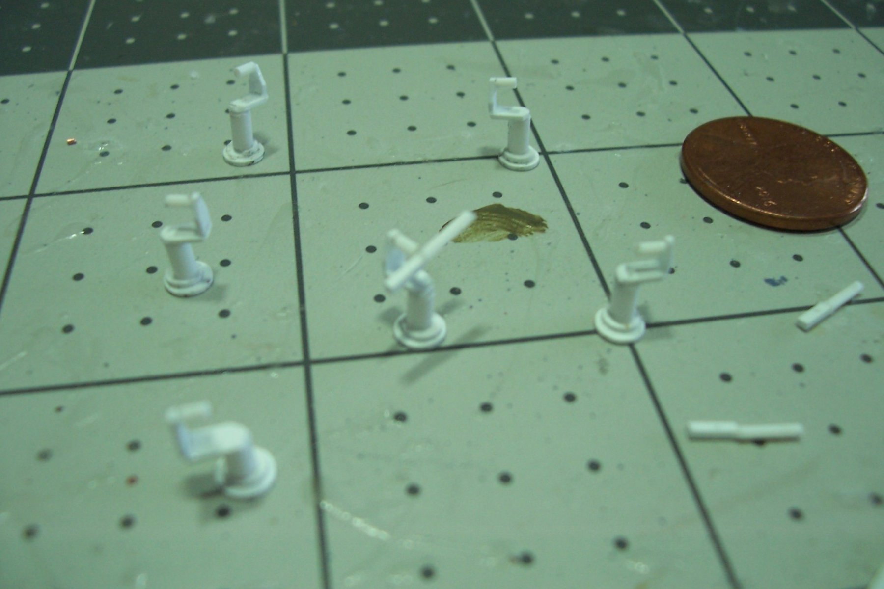
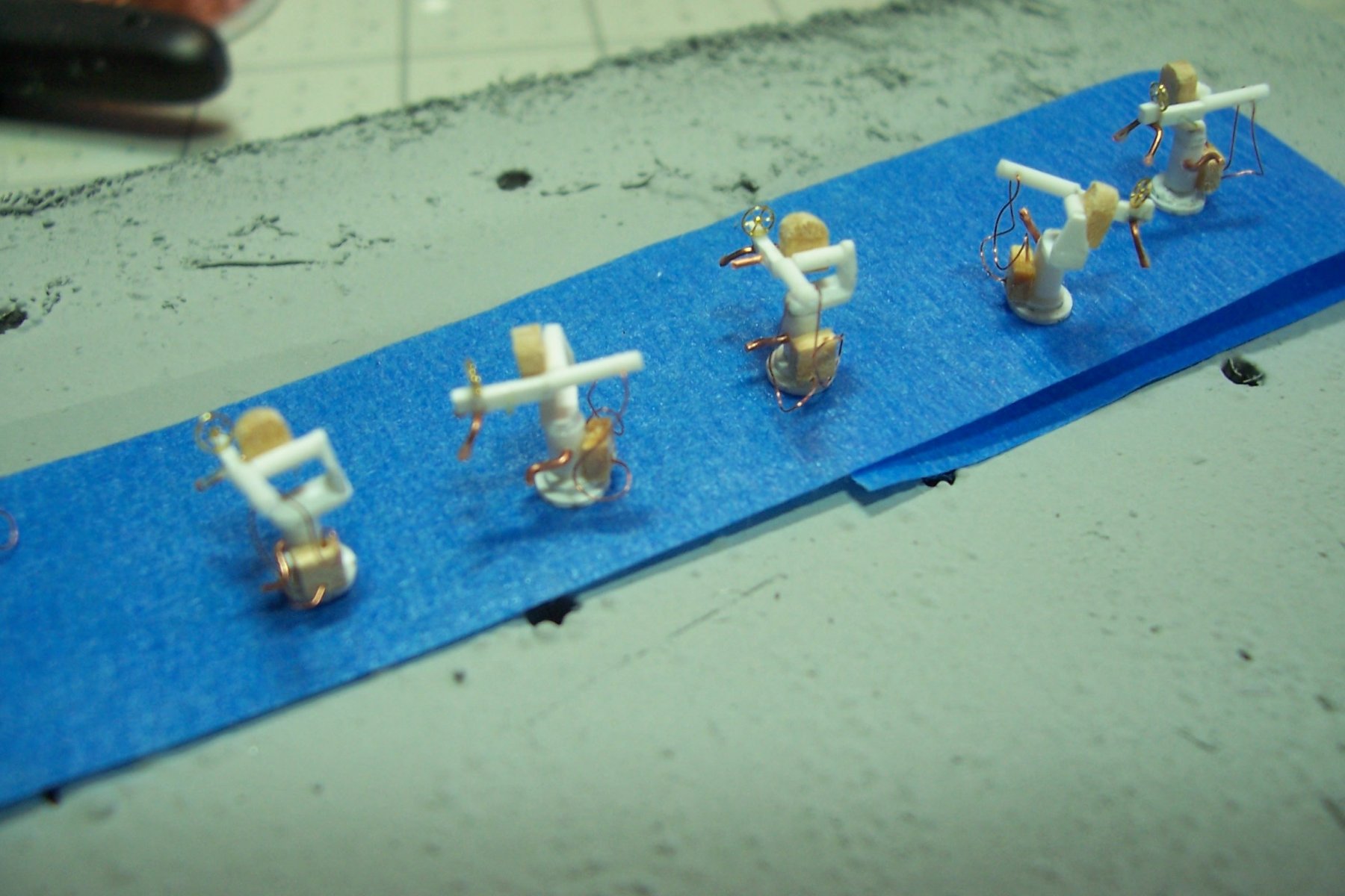
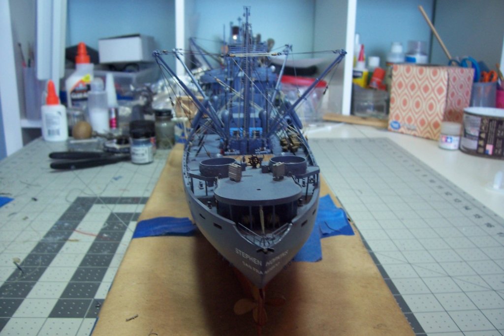
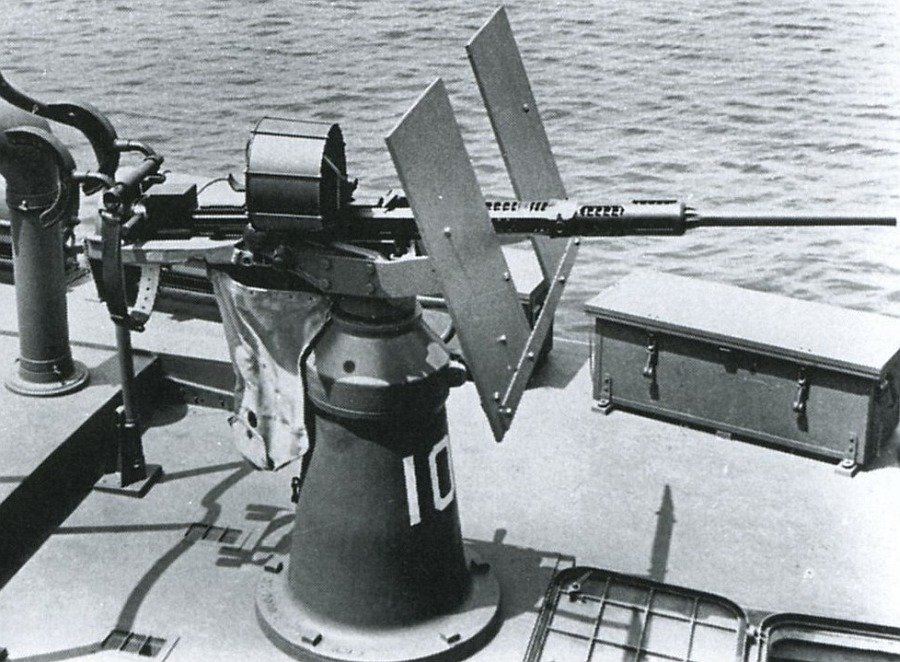
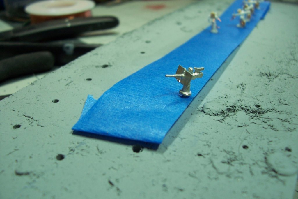
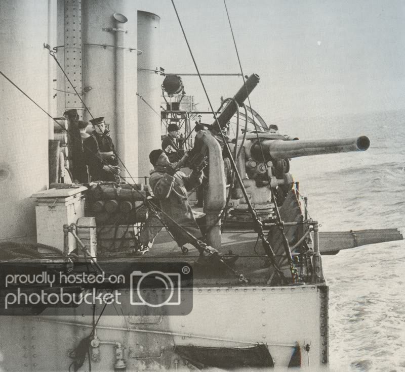
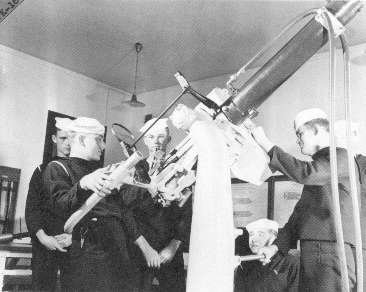
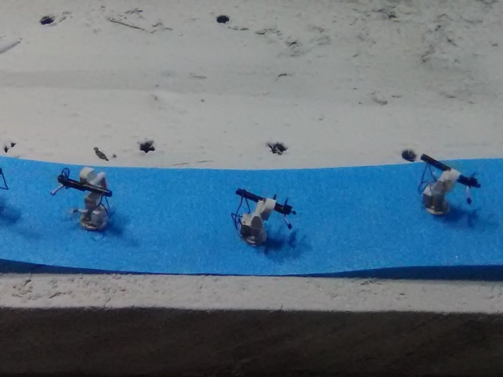
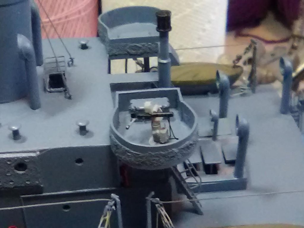
.50 Cal Machine Guns Once the Liberty production line got into full swing by late 1942 their light anti-aircraft weapon suite consisted of 6-8 of the excellent 20mm Oerlikon guns: The kit provides very nice cast Oerlikons: Like everything else weapon-related, the Stephen Hopkins was built too early in 1942 to get the good stuff, her light AA guns were water-cooled .50 cal machine guns from the USN which had plenty laying around since they were rapidly abandoning them in favor of the Oerlikons. When I saw the kit’s 20mm guns I thought it would be easy to convert them to .50 cals by thickening the barrel to represent the water jacket, replacing the cylindrical ammo magazine with the “tombstone” one which was unique to the .50 cals and changing the shoulder rests to the 50 cal grips that looked like bicycle handlebars. The only problem was that I was unable to find any photo evidence that shipboard .50 cals were ever mounted with a shield (unlike today where virtually every USN ship has multiple .50 cals with shields). All of the .50 cal mounts in early 1942 were variations of the “Tora Tora Tora” mounts that were on the battleships during the Pearl Harbor attack, they looked like this: So I needed to scratch build them. I made the pedestals and “C” shaped mounts from strip and rod: The details like the cooling water hoses, water tank, magazine, elevation crank were wire, wood and plastic, the gunsights are Northstar PE valve hand wheels: And the finished product after painting ( I decided to paint the mounts Navy Gray since that is how they would have been shipped and, like any shipyard, they would not have been repainted if it wasn't spelled out in the contract):


- 227 replies
-
- 14
-
-
- BlueJacket Shipcrafters
- Stephen Hopkins
- (and 2 more)
-
Congrats on reaching the end, it took you about the same amount of time as it did to build the real ship!
- 106 replies
-
- 5
-
-
- trumpeter
- john brown
- (and 2 more)
-
Amazing metal and sail work and your ice sheathing passes the dreaded close-up shot with flying colors!
- 82 replies
-
- 1
-
-
- skipjack
- wye river models
- (and 2 more)
-
Very nice build Reed. Before moving to NC my wife and I had many great weekends on the Eastern Shore over 20 years, and like you, I became interested in the skipjacks. I'm currently about 80% done with the Willie l. Bennett kit from Model Shipways, probably the best kit I've found for any build, wonderful directions and plans - learned a lot. I remember reading somewhere that the skipjack design was so successful because it could be built by house carpenters -- not needing any experience with the complex curves associated with most hulls. Not sure if that is true but it sounds good. Great job on the winding machine
- 82 replies
-
- 2
-
-
- skipjack
- wye river models
- (and 2 more)