


wefalck
-
Posts
6,651 -
Joined
-
Last visited
Content Type
Profiles
Forums
Gallery
Events
Everything posted by wefalck
-

removing ca glued rigging
wefalck replied to Lost and Confused's topic in Masting, rigging and sails
Actually, nail-polish smells aromatic not toxic - the son of organic chemist talking -
Your metal work looks just so good and convincing 👍🏻 If I am not mistaken, Tufnol is a kind of cotton-fabric reinforced phenolic resin (Bakelite). It also goes by the trade name of Novotex, for instance. It is normally a kind of reddish mid-brown. It is light, wear-resistant (in the former GDR car-make Trabant, some of the transmission gears were made from it, as well as parts of the bodywork), and weather-resistant. On yachts, block-sheaves and -shells are made from it.
-
removing ca glued rigging
wefalck replied to Lost and Confused's topic in Masting, rigging and sails
Keep in mind, that there are now two fundamentally different types of nail-varnish: the traditional, organic-solvent based one and the newer, acrylic emulsion-based ones. Both require different solvents. -
Timber !!!!!
-
Sitting on that pin must not be very comfortable …
-
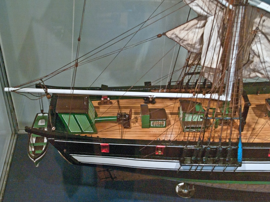
I had a quick look at my photographs of her in the museum and that is exactly the arrangement: One can only guess that the helmsman stood behind the deckshouse and 'rained his horses' from there with the endless tackle.

-
removing ca glued rigging
wefalck replied to Lost and Confused's topic in Masting, rigging and sails
Use fast-drying solvent-based varnish to secure knots etc. Not as messy as CA cement and can be softened any time with the appropriate solvent or acetone. -
1:192 is going to be an interesting scale for a rigged model. It sort of falls between the scales at which you can more or less fake actual rigging practice and the 'miniaturists' scale, where you have to 'fake' everything in the sense that you have visually correct impression, but no functionality. Having to face this challenge in the not too distant future in 1:160 scale, I will follow that REDJACKET project as well.
-
Was there a particular reason, why she had an octogonal pilothouse? It looks rather cramped.
-
You are right, information on pumps for 19th century small ships or boats is rather scarce. The archive of the naval dockyard in Copenhagen has a couple of drawings. I didn't check other sources, as I am currently interested in a vessel from the Baltic. Pumps made from copper tubes along the lines of the galvanise iron one you showed above were available since the 18th century at least e.g. to flush the seats of ease on large ships and for a wide variety of domestic uses. There is no reason, why such pump couldn't be used as bilge-pump. Otherwise, bored-out tree-trunks (probably mainly elm, but also oak or even fir for simple applications) were common and could be produced with a minimum of tooling. Since Roman times water-supply pipes were made like this. They could be also formed from two pieces of timber, banded together and bored out, but I think a tree-trunk was cheaper and less work. An auger basically would guide itself in a straight-grown trunk. In the case of sawn timber one never knows. Looking at the cross-section of your boat, I would think that the pump must have been located near the front end of the cockpit, but I didn't check, whether anything would be in the way of it there.
-
Didn’t I mention in an earlier reply that those scraped and oiled/varnished strakes were common in N-Europe between the 1820s and 1860s, when all black became the fashion. Norway may have held on longer to the old fashion.
-
Nice work on the air-intake and cradles indeed 👍🏻 I am wondering, whether your L-profile was really acrylic ? I have never heard of such small acrylics profiles and most importantly, acrylic is normally too brittle for cold-bending. After bending acrylics (and polystyrene) one should temper it to allow the molecules to re-arrange themselves and thus to take out the shape-memory. Also in the case of acrylic this warm bending can lead otherwise to something that is called stress corrosion cracking. These are very fine cracks that are forming over time. In small painted parts this doesn't matter too much, but it looks not nice on translucent parts. One can do this in a baking oven at 50°C keeping the parts over the former. You re-heating with the hairdryer presumably the same effect. For warm-bending I am using an electrical 're-flow' hot-air soldering gun. The temperature can be set in the range between 80°C and 450°C. Apart from the intended use for touchless soldering, it is useful for all sorts of targetted heating procedures at a fixed maximum temperature, say for tempering hardened steel parts, for blueing metals, bending planks, shrink-fitting, or pre-heating parts for silver-soldering in order to save gas from the torch. I got mine years ago for something like 120€ from ebay.
- 476 replies
-
- 3
-

-
- minesweeper
- Cape
- (and 1 more)
-
Resin ice effects
wefalck replied to JKC27's topic in Painting, finishing and weathering products and techniques
I am using a similar technique for ice as for water that I developed back in the early 1980s or so, albeit with somewhat different materials available then. Basically I glue a sheet of acrylic (perhaps 2 or 3 mm thick) onto a wooden base. There is a cut-out for the (waterline-)model, which has to extend beneath the waterline by the thickness of the acrylic glass.. This wooden base has been painted appropriately to represent the water under the ice-sheet. The acrylic glass is then given a coat of acrylic gel-medium to represent the somewhat irregular water/ice surface. Snow on the ice can be represented by glueing 'micro-balloons', crushed glass (can be bought in hobby stores I think - my supply still comes from my teenage railway model days), or crystalline sugar(!) onto it. This is a good strategy for closed ice-sheets or what is called 'pancake' ice. If you want larger ice-floes, you have to glue with acrylic gel-medium very thin pieces of broken glass (use gloves and pliers and goggles) or acrylic glass before covering everything in the gel-medium. Below is a scene of a Zuiderzee-botter frozen-in that I created some ten years ago: Unfortunately, I don't seem to have taken pictures of the actual process. The scene was based on this picture that I took in Enkhuizen in 2009: It is, indeed, important to study photographs of the situation you want to create.


-
Cutters, Choppers, Guillotines, Slicers
wefalck replied to MintGum's topic in Modeling tools and Workshop Equipment
These chop-saws seem to be copies of the PROXXON KG50, which they offered for many years and is currently priced at 110€ here in Europe. More recently they also offered a heavier version the KGS80, which kost 270€. On the actual topic of this thread: I would rather use a circular saw than a guillotine on materials thicker than a couple of millimeters, particular hardwoods. This ensures square ends. -
Finish of the Waterway
wefalck replied to RossR's topic in Building, Framing, Planking and plating a ships hull and deck
There are many different ways in which the waterways and covering boards were composed/constructed, depending on the period and the size of the ship. Sometimes, waterways and covering board were one piece of timber and in other cases there were two (as in the above drawing) or even three pieces. I have seen drawings/paintings of warship decks, where the waterways/covering boards were painted. In the case of the above drawing, it would be likely, that the covering board is painted, but the waterways are not - would be also easier to realise in a model. -
The confusion between 'right rudder' and 'right tiller' led to the collission and sinking of a historic ship and a container ship on the Elbe river a fews year ago - she was crewed by a partly untrained 'amateur' crew ...
-
There is another interesting arrangement that seems to have been quite common on somewhat larger ships, such as schooners or small brigs, in the earlier decades of the 19th century, where a steering-wheel was put onto the tiller and the endless rope wound around the drum. This made the helmsman to walk with the wheel while the tiller swung around. The above example is from the model of an 1839 brig from Altona/Hamburg, but it seems to have been a quite common arrangement on Dutch ships of that age. I think the arrangement with an endless rope is more conducive to be operated by a single helmsman on merchant vessels with very small crews.
-
Same for me, I need to work out how things work, before confidently being able to model them. Some people just take things at 'face value', but I am not very comfortable with such approach.
-
Perhaps you should have brought in the mother-in-law to clean out the dust ...🙃
-
Perhaps you can find a 'pissoir' instead - somehow the whole French scene reminds of 'Clochemerle' (novel by Gabriel Chevallier), that has been cast into a British TV series - the cast-iron pissoir was blewn up eventually.
-
I agree, seemingly to scale, it still seems out of proportion. Also, they are more likely to be found in larger towns or cities. These columns were invented by a Berlin printer named Ernst Litfaß and the first one was installed in that city in 1854. From there the concept spread all over the world. They often had dual uses, e.g. as transformer stations or covering access staircases to the sewer system. There is a famous scene in the film The Third Man, when Harry Lime slips into one in Vienna - the grand sewer-sytem was notoriously used by criminals to hide or gain access to houses. The Vienna police used to have a specially trained and equipped 'Kanalbrigade' to combat this (they appear also in the film).
-
It seems to have been a very common arrangement until the end of the 19th century on smaller vessels, before steering-wheels were also introduced into them (often only together with motorisation and cutting down the rigs). @Dr PR is right with his interpretation. It's a kind of dampening device and allows a single man to control the tiller on relatively large vessels. There is enough slack in the rope to take a turn or two around a pin (which only protrudes on the top) or knob at the end of the tiller to effectively stop it. Slackening the turn allows one to adjust the rudder. Casting it loose allows faster movements. Two blocks at the end of the tiller seems to have been more common than the sheaves. Many more or less contemporary models show the pin/knob, but the control rope is not always rigged. Sometimes, it seems, only simple ropes, without tackle were used, to simply steady the tiller.
-
This metal-work looks so convincing 👍🏻 Indeed, welded construction is not so easy to reproduce. Perhaps, I would have soldered this over a mock-up of the bow to give the flanges the right angles and distances. There are solders of different melting points, which requires a temperature-controlled soldering iron. The railway modellers who build locomotives from PE brass parts are masters of this art.
-
Zu Mondfeld or not is a question of what you are looking for, information to a specific period or a general introduction? In his later years he tried to stylise himself as the guru of shipmodelling, but a single person can hardly cover all the periods in sufficient depth. So, one has to take what is written in the books with a pinch of salt and corroborate the information against period books for instance.


