


wefalck
-
Posts
6,666 -
Joined
-
Last visited
Content Type
Profiles
Forums
Gallery
Events
Everything posted by wefalck
-
 I began to work now on the various ventilators. These are not of the usual form, but have rectangular cowl. I first drew a layout for the cowl in order to photo-etch them, but then thought the assembly of these two or three millimeter high cowls would be too fiddly. Images showing different types of ventilators on board of a WESPE-class gun-boat As the ventilator-shaft would have to be turned anyway, I decided to machine the vents from the solid. Photo-etching mask for ventilator cowls The first attempt was in Plexiglas, because it is easy to machine and the cover part from polystyrine foil could be easily cemented on without traces using dichloromethane. It turned out that at thin wall thickness required, Plexiglas would be too brittle and delicate. Setting up rectangular material in the 4-jaw-chuck Turning the ventilator shaft Drilling out the cowl For the second attempt I used brass. While in the case of Plexiglas I began with a rectangular piece held appropriately in the independent 4-jaw-chuck, I started now with a round brass bar held in the excentric 2-jaw-chuck. If I did not have such an exotic chuck, I could have started off with a larger diamter brass bar and milled away the excess. Setting up a brass rod in an excentric 2-jaw chuck As a first step the ventilator-shaft was turned to size, leaving also the two re-enforcement rings. The piece was then turned around and taken into a collet of the appropriate diameter to drill out the shaft to such a depth that the bottom would not be visible. Turning the re-enforcement rings Drilling out the cowls To be continued soon ...
- 935 replies
-
- 10
-

-
Just another thought: wouldn't these life-boats on a lake-steamer normally be protected by a tarpaulin-cover ? So perhaps you make four solid hulls according to the lines plan and cover these in thin strips of wood to simulate the clinker planking and the just put the tarpaulin over them. That saves you doing all the details of a wooden open boat. Or perhaps to do one to 'show off', namely the one that would be ready for emergency lowering, while showing the others covered ? I have nevera actually laminated a hull, but if you did it over a positive form, it would not involve too much material.
-
Brass thumbscrews seem to be difficult to come by on ebay indeed, but you can get them quite cheap in steel: https://www.ebay.com/sch/i.html?_odkw=thumbscrew+M3&_sop=15&_osacat=0&_from=R40&_trksid=m570.l1313&_nkw=thumbscrew+M3&_sacat=0 Luckily I have a domestic source here in Paris , which is quite unique actually.
-
It is a bit on the large side for home-application, but you could create two clinkered solid half-hulls and then take copies of it by thermoforming or resin-lamination, if you want to forgo the joy of making real clinker-boats ...
-
I could add to the list of references: BEAUDOUIN, F. (1975): Bateaux des côtes de France.- 394 p., Grenoble (Editions des 4 Seigneurs). Unfortunately, I don't have access to my copy at the moment and cannot check, how useful it would be for the region/boats in question. BTW, the Musée de la Marine in Paris is closed for refurbishment. Not sure what is in their archives, but certainly they had no models etc. on show of relevant boats. If they have something, it may come from the collection Admiral Pâris started.
-
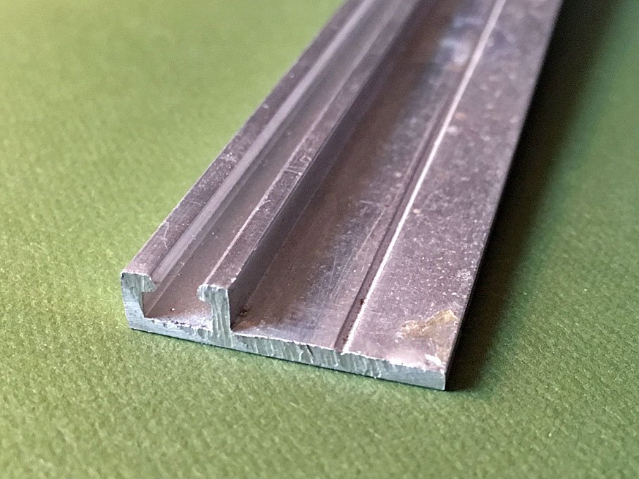
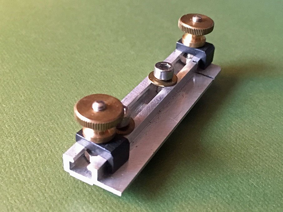
It is the aluminium-profile below. Found it at some stage in the basement of my parent's home and have no idea where it came from and what it was meant for. The overall width is 25,4 mm, i.e. 1". I used it to make various jigs and little tools, where one would need T-nuts to hold down things - the T-slot is just the right size for M3 screws with hexagonal heads as T-bolts. For instance the little gadget below screws to the T-slot of the cross-slide table of my watchmakers lathe and allows to cut to length small profiles etc. The material is held down by the black clamps.
-
size of people
wefalck replied to Snow's topic in Discussion for a Ship's Deck Furniture, Guns, boats and other Fittings
I found that I carry a good pocket calculator around with me most of the time: my iPhone It does everything you likely ever need, including square roots and sinus and cosinus. -
I gather a metal base is there for the weight, but a tile on some wooden base-bord would be another option. I have a bunch of aluminium T-rails (one could use also curtain rails) and was thinking of utilisising them for exactly that purpose.
-
Not quite sure what part you are referring to, but I assume it is a piece with a sculpted or moulded surface ? There would be two options, depending also on whether the part is already attached to the model or not: - you can paint all over and then immediately wipe-off the paint from the high parts with a lint-free cloth - if the fitting is not attached yet, you can carefully degrease it and the immerse it in a chemical blackening solution; once blackened take it out and rinse carefully; in the next step you can polish the high parts with some 0000-grade steel-wool until the brass becomes shiny again. In all cases, the parts should be varnished, as brass will tarnish with time. There are special varnishes for brass (collodium dissolved in nitro-thinner basically).
-
The real problem with too bulky knots is that the thread used is to thick. One should carefully select the size according to scale. When it would be descernible at the scale, I tend to use the actual prototype knot. Otherwise, I am using most frequently the clove hitch and half-hitch. I prefer the clove hitch over the constrictor knot, if there is a chance that I might need to untie it again. Belaying would also follow prototype practice, if at all practicable. Where splices were used, I would make false splices, i.e. I would draw the end through itself twice or three times with a needle.
-
I cannot comment on US American practice of piloting in mid-19th century. However, over here in Europe, piloting at that time was a business, albeit with certain government rules, regulations and oversight. The pilot schooners or cutters really were 'motherships' for the pilot-dinghies. The pilot-boat that first hailed a ship usually got the job. For this reason, pilot-boats cruised far outside the harbours or estuaries, say Hamburg pilots as far as Helgoland or off the Dutch coast. That is why pilot-boats had to be tough and seaworthy, to be able to remain on station even in atrocious conditions. It is impossible to approach another ship with a pilot-boat in anything but flat sea, if they didn't bump into each other, the rigs could get entangled, when the vessels were heeling over. So the only way is by using a dinghy. There would be a couple of men in the dinghy and the pilot. They would approach the ship while it may be moving up and down several metres in a heavy sea. At the right moment the pilot would have to jump and grab the ladder that would have been lowered for him from the ship. The dinghy then would push off as quickly as possible in order to not get caught by the ship. Taking the dinghy on board the pilot-boat was another dangerous exercise that required a lot of skill. Putting the dinghy out already was a tricky job: it would hang with all men aboard from the davits and the quick-release gear would have to pulled at the right moment in a heavy sea so that the boat dropped into the water on an even keel, but not too high. Pilot-boats had several dinghies on board, one or two suspended from davits for immediate use and perhaps one or two spare ones. The boats carried around six to eight pilots for whom sufficient living quarters were amidship. Once all pilots had been employed, the pilot-boat would return as quickly as possible to its base in order to pick up the pilots released from the docked ships and the return back to its station as quickly as possible - that's why pilot-boats had to be fast, to compete against other pilot-boats.
-
HMCSS Victoria 1855 by BANYAN - 1:72
wefalck replied to BANYAN's topic in - Build logs for subjects built 1851 - 1900
I think these chains were called 'preventer chains', as they were meant to prevent the the loss of the rudder should it become unshipped. One can see them on many models. Here is an example from the BELLE POULE in the museum in Paris: The idea of hanging the chains festoon-fashion presumably was to distribute the load, so the fastenings would break one after another. Overall the chain had also to be long enough, so that the rudder floats as clear of the ship as possible - otherwise it could do some serious damage to the hull. BTW, didn't see your post of 11 December until just now: yes this is the self-tinning solution I have.- 1,021 replies
-
- 4
-
-
- gun dispatch vessel
- victoria
- (and 2 more)
-
Thinking of didn't 'archjofo' use in his log on LA CREOLE a ceramic soldering plate with pins and clamps to hold down parts ? Couldn't find quickly the relevant picture(s)
-
"Others looking at your sagging rigging will just think you did a poor job." - quite likely so ... same problem when reproducing a roughly built prototype ... On running rigging, where loose and sagging looks more plausible even to uniniated bystanders, I have tried to reproduce the sag by wetting the line with fast-drying varnish and running a piece of wire along the line to maintain the catena (+/-) until the varnish has dried.
-
Hi Pat, I don't actually recall having seen here anything that matches your description. If you find it, I would be keen to see it too ... In the meantime, below is a small clamping device or sub-table I made for the milling machine a few years ago. It basically consist of an aluminium bar with a T-slot milled along one of the sides. This T-slot allows to clamp two holding-down fingers anywere along the table. Two shorter fingers act as stop for the part, while it is worked on. A plate at the back of the block acts as fulcrum for the holding-down fingers and can be raised and lowered accordingly. The whole things screws down onto the milling machine table with two screws and T-Nuts. Incidentally, talking about holding-down fingers: you may want to google for 'finger plate' and will find various more or less clever devices for holding small parts. E.g. here: http://www.modelenginemaker.com/index.php?topic=1434.0 http://www.homemodelenginemachinist.com/showthread.php?t=13004
-
Yep, it is a standard fitting on small sailing boats - the advantage over the closed type is that you can take the rope in and out without having to reeve it through a hole. Their are commonly used at both ends of a boat for mooring lines or also for anchor lines - in both cases you may not want to take the line of its belaying point when hauling in or paying out - in case it slips from your hands.
-
There is and was probably a big difference between commerical and naval vessels. As has been pointed out before, on naval vessels intensive maintenance was both, a necessity to maintain a good fighting capability and a work-therapy for large crews that otherwise would become bored and unmanagable very quickly. During WWI and WWII particulary the axis powers faced supply chain issues, lacking spare parts and materials. War losses also meant long duty-cycles with only short breaks. All this together had its effect on the appearance of say German ships. Apart from the aspects of owners' and master's pride, crews as small as possible meant also that maintenance was only carried out when really needed and there was the spare time for it. So, after a rough trip across the North Atlantic they may not look their best. Or, fishing vessels constantly moving between ports and fishing grounds will look rather worn, at least during the season - maintenance is carried out during the off-season. There are plenty of old photographs that show particularly smaller ships involved in local trade are not all 'shipshape and Bristol-fashion' as Dana put it. Coming back to the original question: I used a mixture of approaches, namely washes with burnt umber (I would rather avoid black as being too stark) and white, as well as a dusting with white pastels. It may be worthwhile to have a look at what railway modellers do, who sometimes are quite fond of the aged and degraded. Belwo is an example not of a real wood-deck, but a painted one. However, the weathering technique would be more or less the same:
-
Well, here in France strikes are very common, but usually affect only parts of the system, as there are different unions on different lines. Good thing that I work from home most of the time ... Photographs pre-1880 are a big problem in Germany. There weren't that many photographers at the time that would take pictures outside of studios. And again the war-losses are probably significant. So, it might be very difficult to come by pictures unless they had been published somewhere before WW2. My grandmother used to live next door to the most eminent naval photographer family in Kiel - I think they ran the business for four generations from around the late 1860s on. My father already told me once that their archives were lost during WW2 and some 20 years ago I visited the last in the row, who kept the business going until a few years ago. He confirmed that virtually all their negatives had been lost and that he in fact was trying to rebuild to some extent their archives by obtaining copies from published and private sources. As to rigging, there are a couple of German text books from the late 1840s and a bit later that can serve as a guide. Nevertheless, if I can be of any help, let me know.
-
Hi John, this project has escaped my attention completely until today ... didn't have much time to browse building logs these days ... I had know the two paintings for years, as the older one has been reproduced in a calender in the mid-1970s and then later also in various books. I am also very interested in this period of shipbuilding. There are notable differences between the 'clippers' of these days and the real ocean carriers that probably carried the bulk of goods around the world (for which no premium would be paid for fast arrival). It also seems that the German ships of the time were much fuller around the bows than the British or US American ones. Unfortunately, the last war, natural desasters (e.g. the 1962 flood in Hamburg), and negligence after the shipyards went out of business lead to most records (including ship's plans) being lost. There are also very few models of commercial ships from that period that survived. So it is indeed not easy to collate a good database for a model reconstruction. Would you mind showing the drawings you did for her ? At the Altonaer Museum in Hamburg they had before WWI build a series of typical ships of the 19th century, based on plans in the Museum and also first hand knowledge of the people working on those models (which has its good and bad points). Here is one example: (Apologies for the poor image quality, but the lighting is not so conducive to visitors taking pictures, plus the glass cases) I full series of images can be found here: http://www.maritima-et-mechanika.org/maritime/hamburg/altona.html, but I focused on the smaller units, as I was collating material for another model reconstruction project. If you need help in reconstructing deck fittings and rigging details, I can probably mobilise friends around Hamburg/Bremen/Brake to take pictures of models preserved in the various museums. As someone mentioned the book of Däbritz and Quinger a word of 'warning': these authors mainly worked with material from the museum in Rostock at the Baltic coast. The Baltic coast seemed to always lag behind a bit in development and did have other commercial constraints/incentives than the world-trade ports of Hamburg and Bremen. In consequence, there are notable differences in the lines development and appearance between ships from the Baltic and the North Sea. Looking forward to see this project evolve ...
-
Given their size and weight, it would be impossible to put so much tension on them that they were completely straight. There is always a slight catenary in them.
-
You are probably talking of Stockholm Tar, which is obtained from resinous trees and has various shades of brown. Since the middle of the 19th century more and more tar as residue from coking hard coal - to obtain gas for illumination and to make coke for steel-making, became available in large quantities. This tar is black in concentrated form and dark brown in thinnish layers. So one needs to make distinctions for different historic periods. However, this has been discussed repeatedly already on this forum. In general, I think the ratlines might be lighter in colour, as their material may have been treated only during the manufacture, but not after installation.
-
You are right in principle, but achieving a uniform catenary as it were for all the shrouds, stays and back stays would be difficult to achieve. In practical terms I would go for uniform straight standing rigging. If you don’t get the catenary right, the model will look messy and poorly executed.
-
Small desktop mill for modelling
wefalck replied to Roks82's topic in Modeling tools and Workshop Equipment
... that was exactly my thought, when I started reading the thread. The nearest dealer for Slovenia would be CoolTool in Mödling near Vienna (www.thecooltool.com). I did have some dealings with them during my time in Vienna actually. I was surprised to learn, however, that Sherline doesn't mind shipping directly and I bought from them back at a time, when I was an international civil servant and didn't need to pay import duties. The latter is a serious consideration when ordering in the US. Plus, the US Postal Office changed their shipping plans a few years ago and abandoned the cheaper 'surface' mail - which was good value, if you had the patience to wait for your parcel for up to three months. P.S. The CoolTool guys call the Sherline mill UniMill and the lathe UniTurn ... -
The truth may be, as so often, somewhere in the middle. I gather ratlines typically would have been made from material heavily soaked with tar during the making - as pointed out above. So they would be of some greyish-brownish colour, given also the weathering and salt deposits. I would try to avoid too stark contrast to the rest of the standing rigging and blend them somewhat in. The same applies to the running rigging, I think the contrast to the standing rigging should not be too stark. The smaller the scale, the less contrast I would go for.
-
Model Shipway Ratline tool
wefalck replied to fnkershner's topic in Modeling tools and Workshop Equipment
Question: how did you actually tie your knots ? I use tweezers in each hand and start from the middle, not from the forward or rear shroud. This reduces the risk of pulling the shrouds together. If a piece of cardboard with the shroud/ratline layout behind the shrouds is not enough as guidance, you may think of several strips of cardboard with notches in the distance of shrouds distributed along the shrouds as spacers. This prevents them from being pulled together. If your knots don't stay tight, you probably used the wrong or too thick material for the ratlines. Actually looking at your pictures, I think this is the problem. The ratlines are much, much thinner than the shrouds. In real life they may have perhaps a diameter of 1 cm or so. In real life as on the model: a thinner line holds better on the shroud, but it cannot be too thin, otherwise it would cut too much into the (bare) feet of the sailors and of course it has to carry their weight.