HOLIDAY DONATION DRIVE - SUPPORT MSW - DO YOUR PART TO KEEP THIS GREAT FORUM GOING!
×


EdT
-
Posts
2,213 -
Joined
-
Last visited
Content Type
Profiles
Forums
Gallery
Events
Everything posted by EdT
-
Hello, Richard. I do plan to rig the full framed, 1:72 version of the model. We expect this to be the subject of Volume II. However, the second volume is planned to equally apply to either version of the model and sufficient information will be included to support rigging either one. Ed
- 3,618 replies
-
- 7
-

-
- young america
- clipper
- (and 1 more)
-
As Bob points out, the purchaser of the book has the right to make copies for personal use. I perhaps should have added that the author accepts no responsibility for reproduction errors by third parties - or by the purchaser for that matter. We included these as pdfs with illustrated printing instructions in response to comments by readers of earlier books that the single print soon gets soiled and needs to be replaced or for those who want to retain a "good copy." We aim to please. As to the the ease of attaching and aligning the drawing on the shipway, I have found attaching and replacing small sheets quite easy and in fact continue to use the method even though I have the ability to print these on one sheet, so I will continue to advocate that simple approach. However, you have the choice. Since this topic is related to the book and therefore both versions of the model, I'd like to suggest that further comments and other book issues be placed in the book topic in the book reviews section. Ed
- 3,618 replies
-
- 8
-
-
- young america
- clipper
- (and 1 more)
-
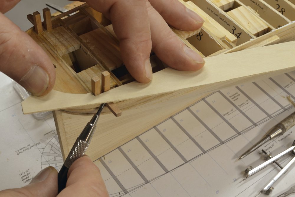
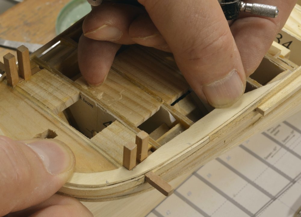
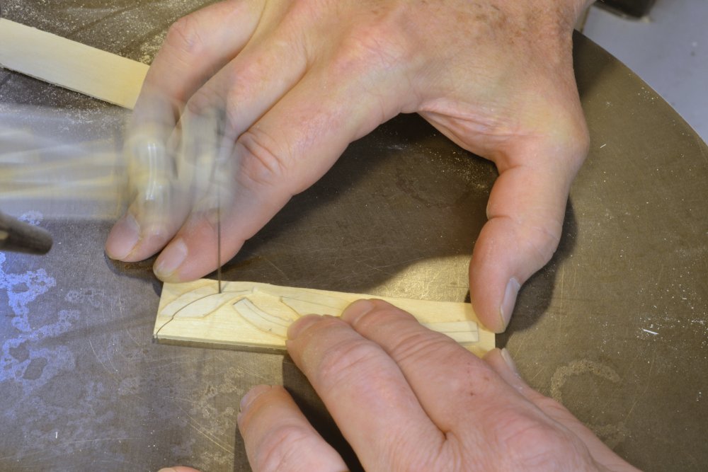
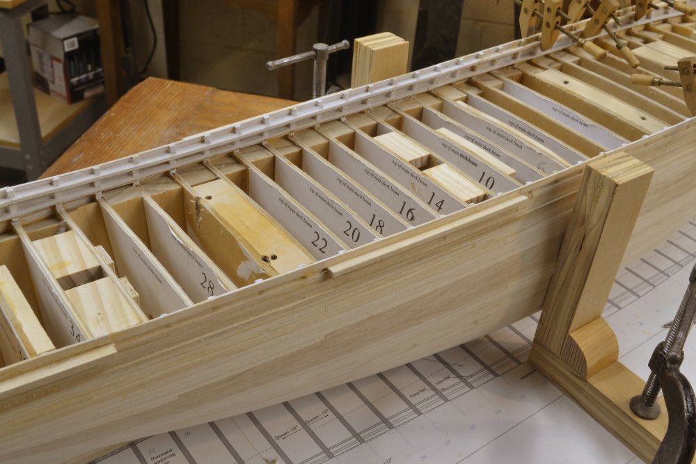
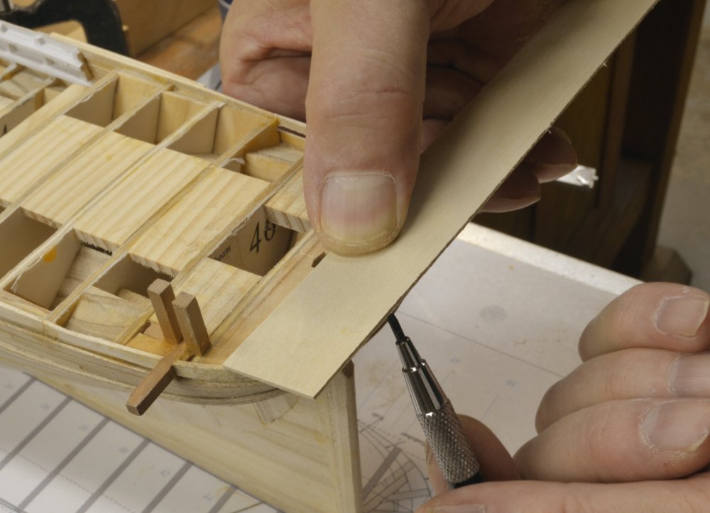
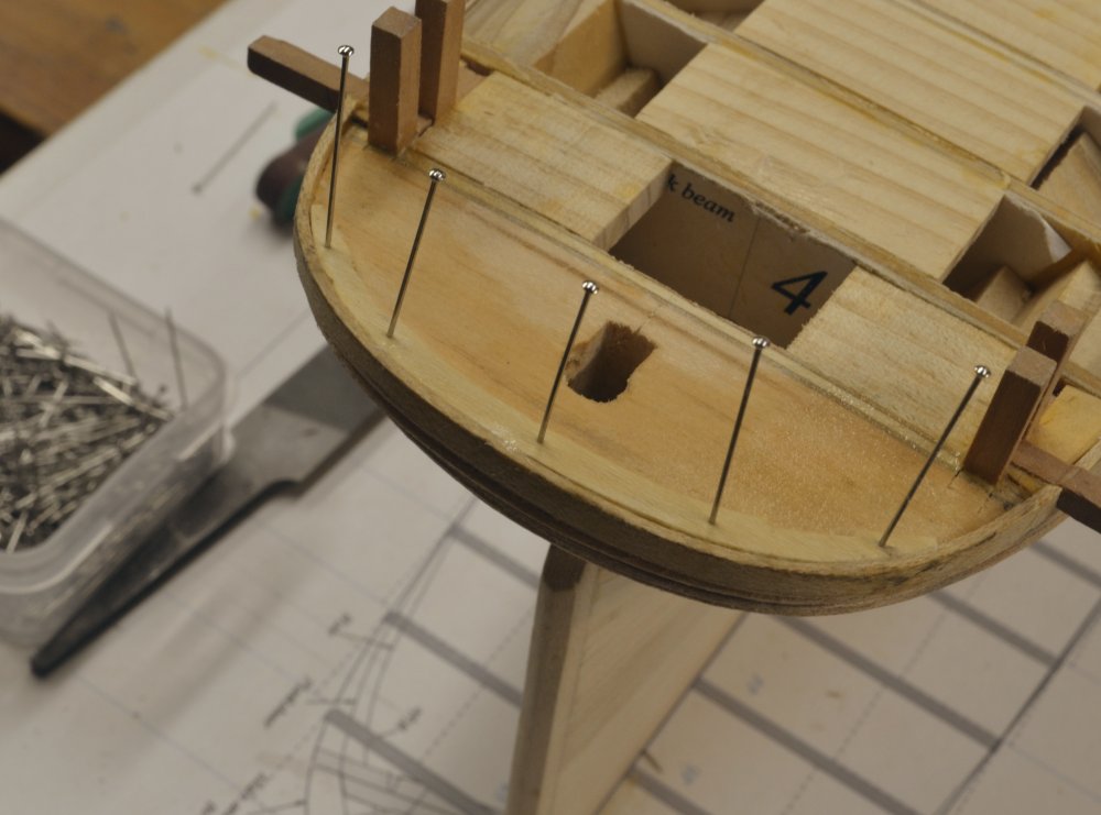
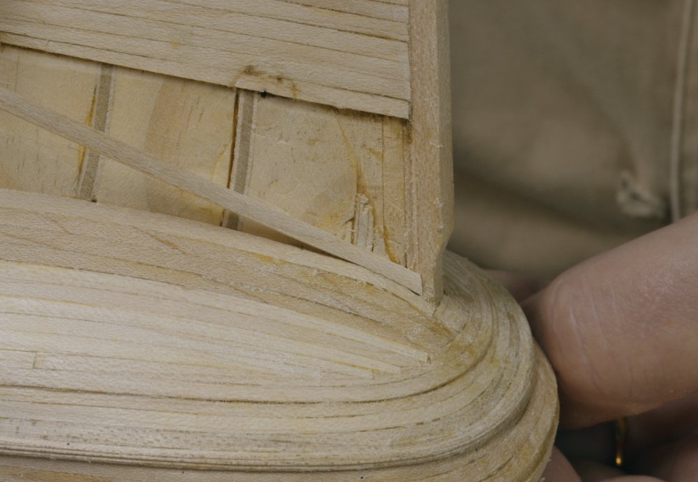
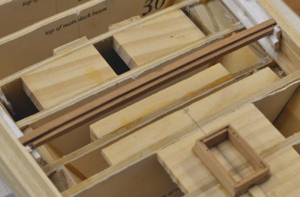
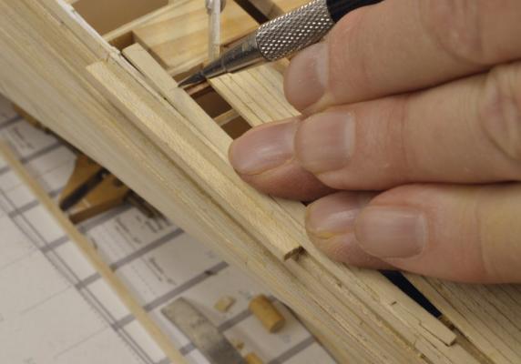
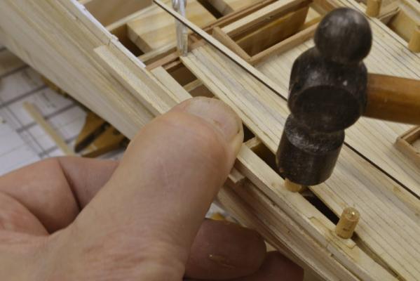
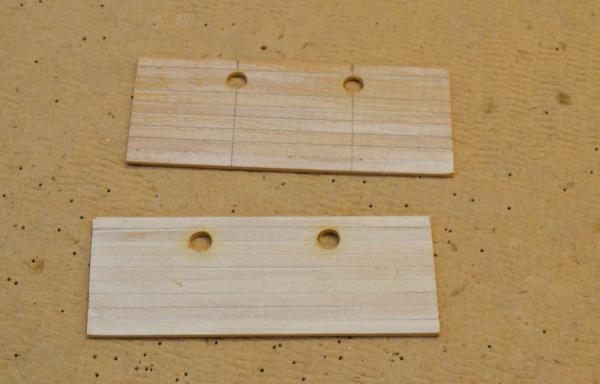
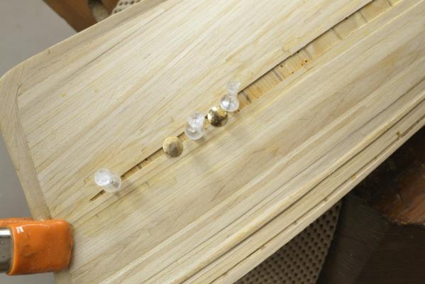
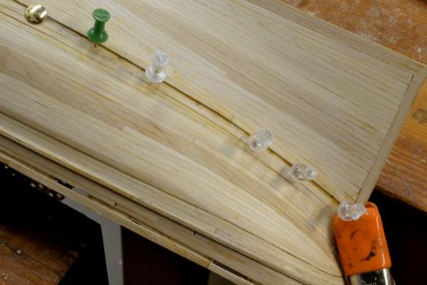
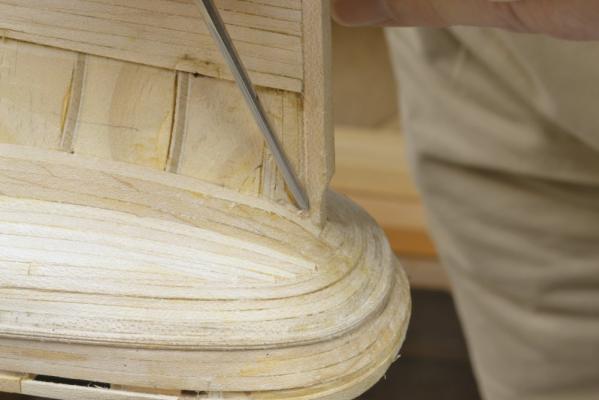
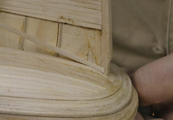
Young America 1853 – POB 1:96 Part 29 – Poop Margin Plank 2 After installing the stern section of the margin plank, the next sections forward were made and installed as described below. In the first picture a sheet of 3 ½” holly has been cut and notched to fit against the two mooring bitts and the outside curve of the piece is being traced as was done at the stern. If I have not mentioned this yet, I did use some holly I had to do the deck planking. The white holly gives a good simulation of the salt-bleached decks of the white pine that was originally used. I used Castello on the larger model. In the next picture, the outside line has been cut and the piece is being fit inside the topmost outboard plank. The breadth of the margin plank was then marked out using the compass as shown below. This is a fairly wide plank – wide enough to butt and joggle deck planks into it inside the cap rail that will be installed later. Again, to avoid breakage at the curved end of this piece when sawing, it and the piece for the opposite side have been pasted to plywood. The curve of the starboard piece is being cut in the next picture. In the next picture, both pieces have been installed. The fit against the outside planking does not have to be perfect, since it will be covered by the capping fancy rail. This picture also shows hatch coamings and decking that I worked on concurrently. This will be covered later. To finish off the margin planks at the forward end of the poop deck, the breast beam needed to be in place. This is shown installed in the next picture. This beam is at station 36, forward of the first poop bulkhead at station 38 to allow some overhang of the forward end of the poop. It was rounded up by a process similar to that used for beams on the larger framed model – but with some differences that I will describe later when the forecastle framing is covered. Rather than cut the rabbet on the top of this beam, a 3 ½” strip was glued across the top. It overhangs the forward face of the beam by about three inches. In the next picture the hook scarf at the end of the relatively straight forward section on the port side has been cut and the length to the rabbet on the breast beam is being marked. In the last picture the plank is being glued down with the aid of some homemade pin clamps. I will describe these later. In the picture most of the poop decking has been installed. I worked on a number of things concurrently. This other work will be described later. Ed


- 191 replies
-
- 23
-
-
- young america
- clipper
- (and 1 more)
-
HI John, All the files shown in the last post are Grobet Swiss files. I believe they are all #0 cut (coarse) - if these are the ones you refer to. If not let me know which post and I will be more specific. I use a variety of these. I also use fine cutting rasps by Iwasaki that I like. These are reasonably priced. You can pay anything for a good rasp. I think I got these from Woodcraft. I usually purchase Grobet files from Contenti, a jeweler's supplier, since they have a broad selection. You will not have trouble finding other sources. Here's a link to Contenti: http://www.contenti.com/ Ed
- 191 replies
-
- 6
-
-
- young america
- clipper
- (and 1 more)
-
David, the purpose of pasting the margin plank to plywood was to strengthen it for further cutting and forming of the hook scarphs at each end. Because of the grain direction at the ends and due to the relatively low strength of Castello across the grain, this was necessary to avoid having the ends break off during cutting. I used ordinary school paste sticks for this and the worked very well. Ed Correction: I used holly for this piece, not Castello.
- 191 replies
-
- 7
-
-
- young america
- clipper
- (and 1 more)
-
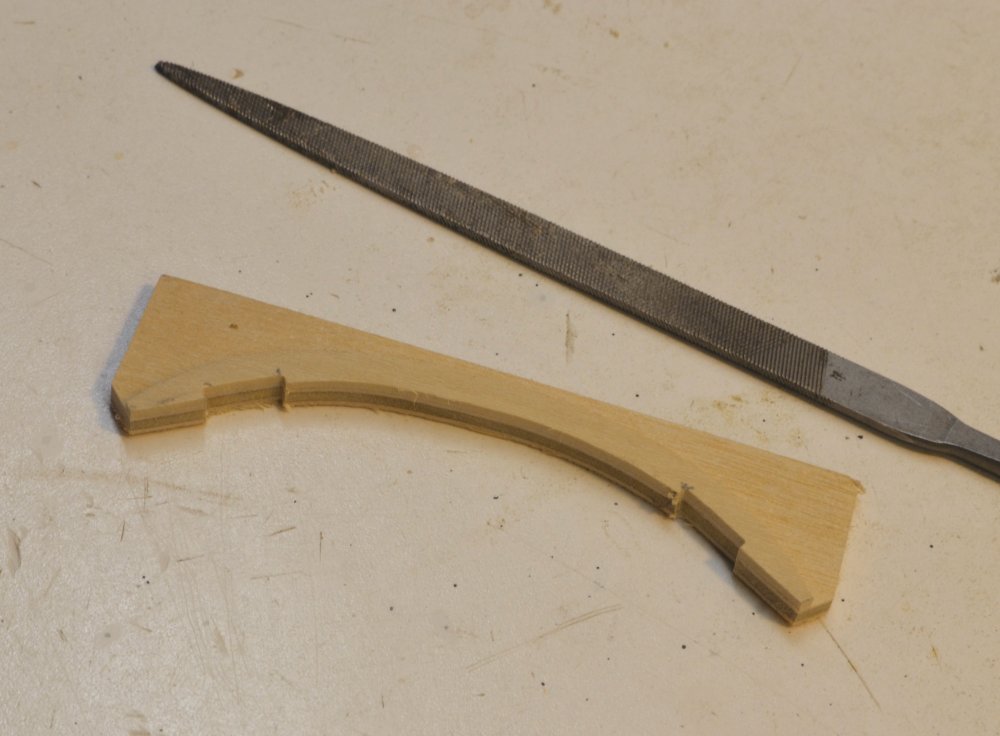
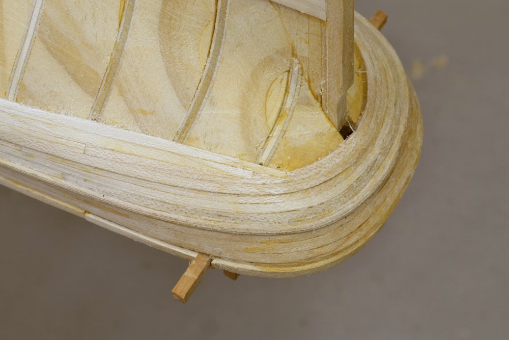
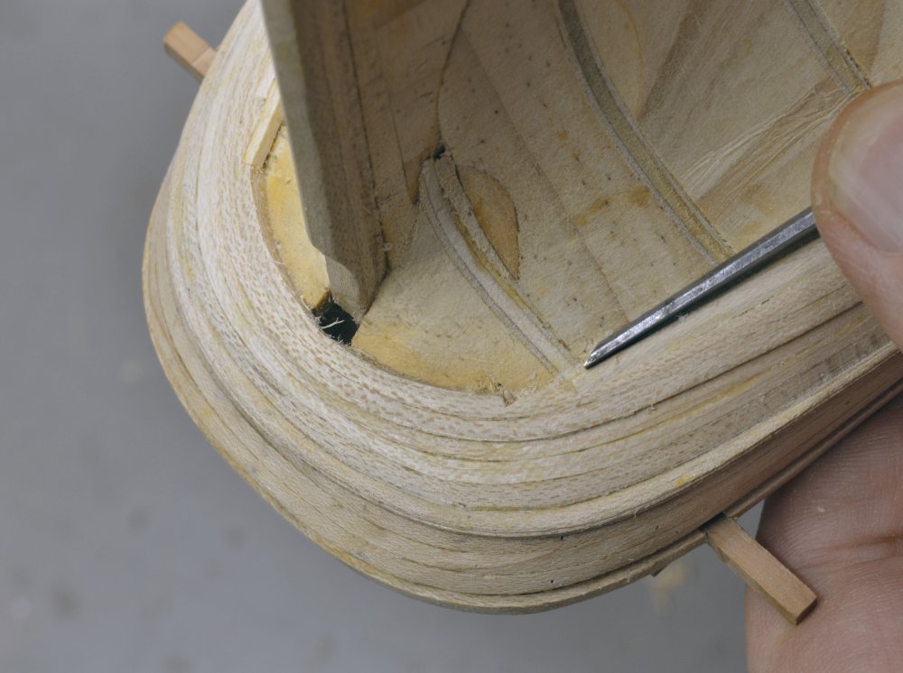
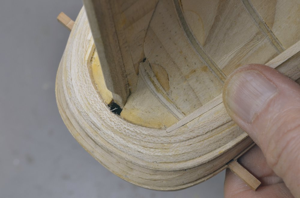
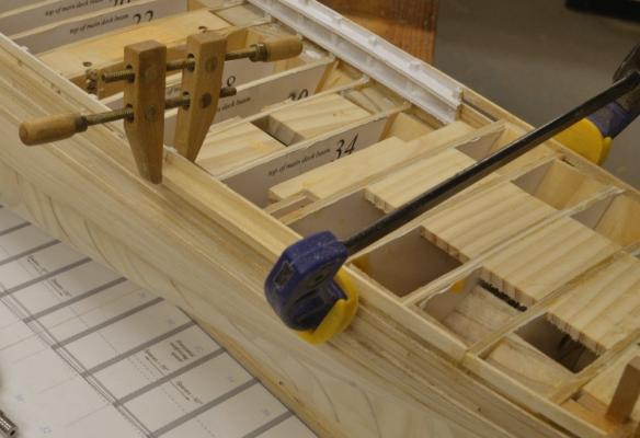
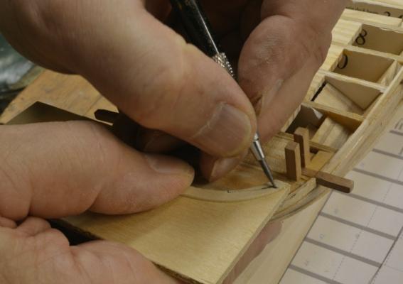
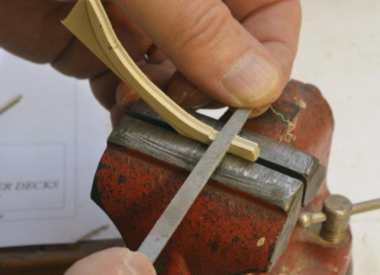
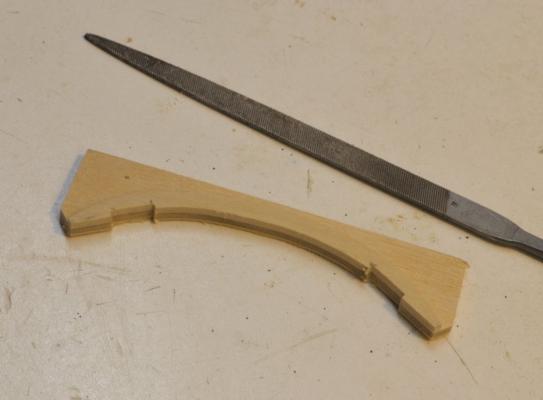
Young America 1853 – POB 1:96 Part 28 – Upper Channels/Poop Margin Plank First let me say that although I am now posting to both this log and the 1:72 framed version log, I am not working on both of these simultaneously. I needed to do this in the spring and it damaged my sanity – reading dimensions off the wrong conversion chart of the two posted in the shop being one frequent occurrence. The final posts on this log cover work that was done in August and September to prepare this model for the NRG conference. These next several posts will complete the online material for this POB version that I offer to those who might build the model – as a supplement to the content in the book So, the next task after finishing the outer planking was to install the upper channels. This is straightforward work. The six inch thick channels are merely cut to length and glued into the slot left for the main rail. The port upper mizzen channel is being glued in the first picture. The channel is clamped to pull it into the slight curve of the hull and to keep it horizontal. Although I did not do this for the model, to support rigging the channels should probably be bolted through each frame timber with functional wire bolts. These are described in the book. The wire becomes a real fastening by fixing it with epoxy glue all the way through the hole. The next picture shows the two forward upper channels being glued in. The next picture shows the main upper starboard channel in place. The lower channels were installed later. The next task – necessary to begin decking of the poop – was to make and install the poop margin plank at the stern. Poop planking butts into this curved plank. In the first picture the approximate shape of the outer edge of the stern section is being sketched in by tracing around the stern. The plank actually fits inside the upper strake of outer planking, so after cutting it out to the rough line it was fitted more precisely inside of the upper side plank. The top of that plank had been set higher than the beam height by the thickness of deck planking – in this case 3 ½”. In the next picture the fitted curved plank has been pasted to some 3/32” plywood to reinforce it for cutting the inside edge and shaping of the two hook scarph joints at the ends. In the picture the inside line has been marked out, cut on the scroll saw and the joints are being marked out. Next the joints were filed out with the reinforcing plywood still pasted on. The completed margin plank is shown in the next picture, still attached to the plywood. The plank was then lifted from the plywood with a hobby knife and the paste residue washed off. The piece was then pinned and glued as shown in the last picture. Only minimal sanding was done to this piece at this stage – just enough to produce the fair inner curve with no rounding of the forward edge. This will allow the deck planks to butt neatly. In the next part, the margin plank will be extended forward along each side to the breast beam. Ed


- 191 replies
-
- 16
-
-
- young america
- clipper
- (and 1 more)
-
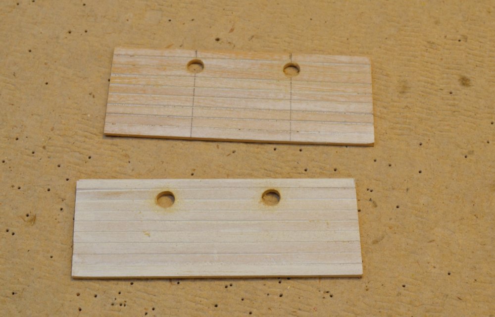
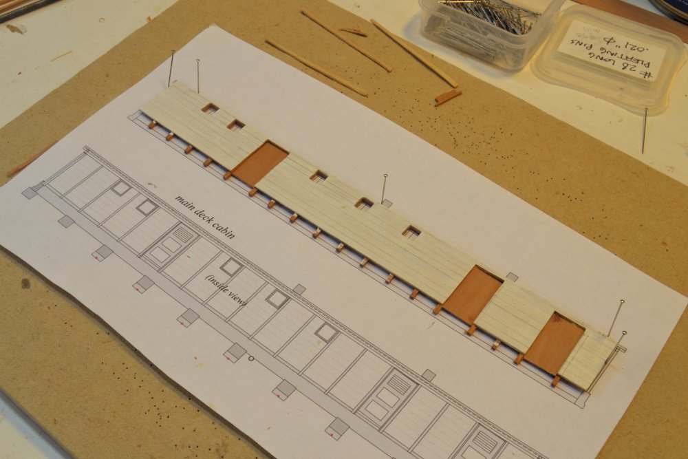
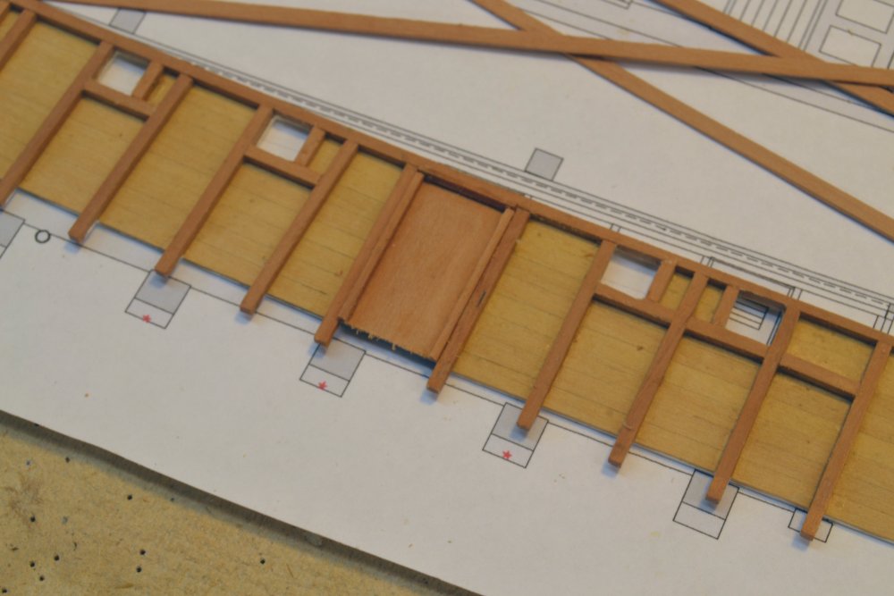
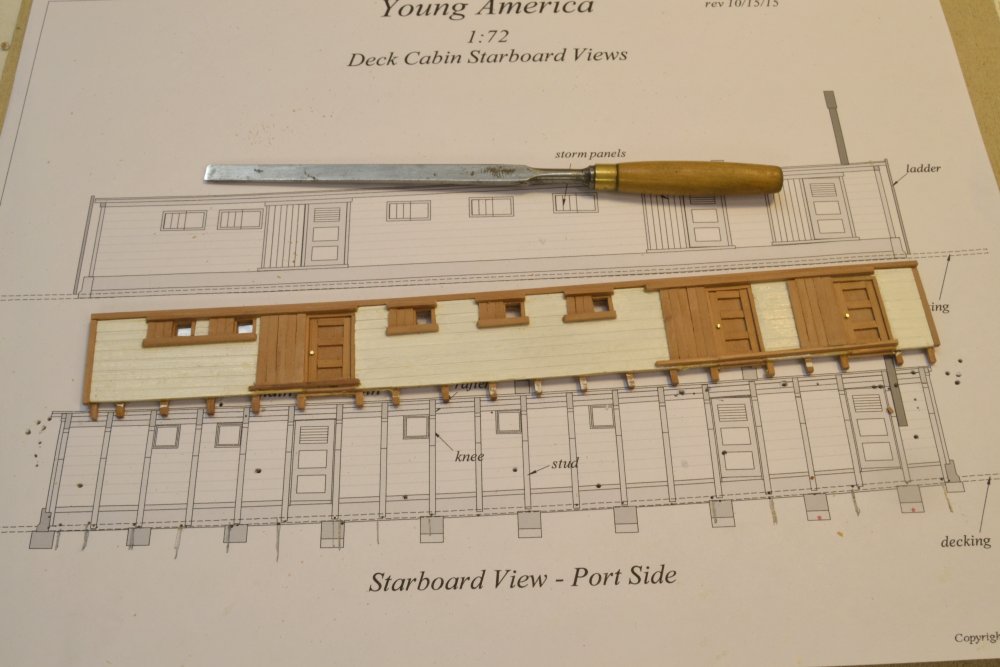
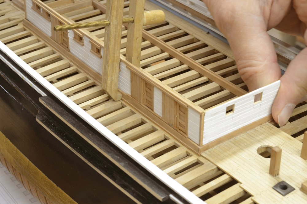
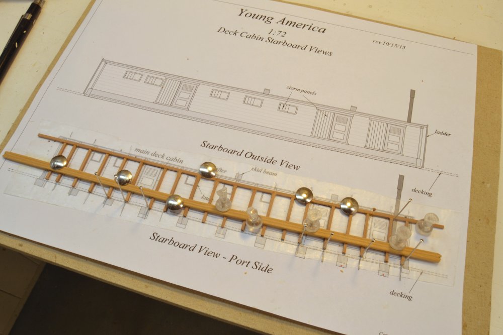
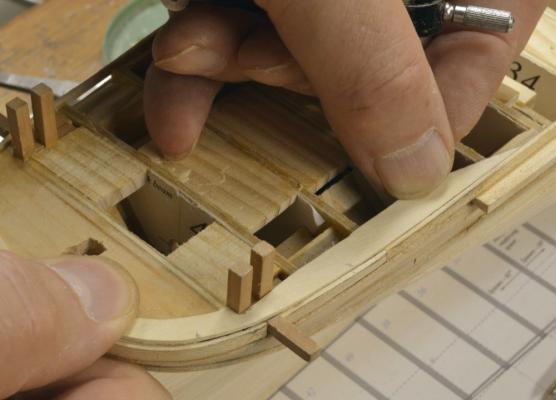
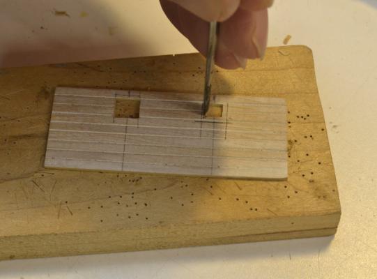
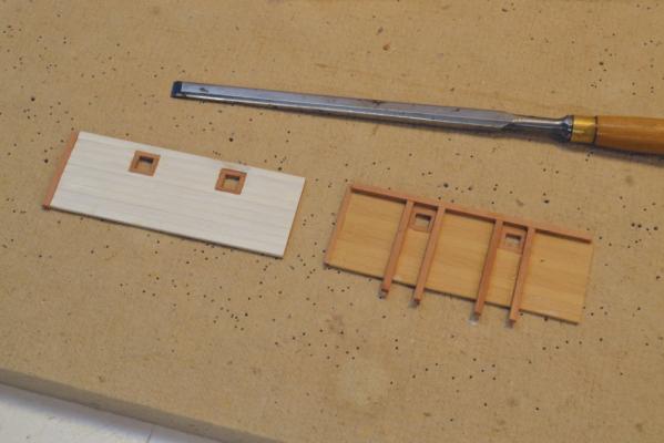
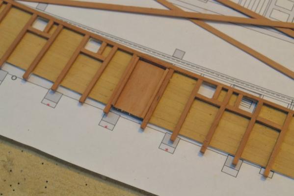
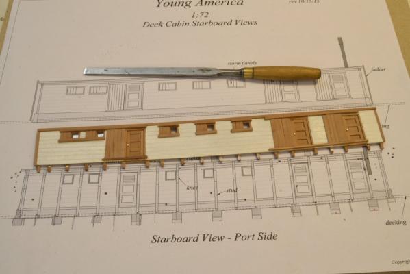
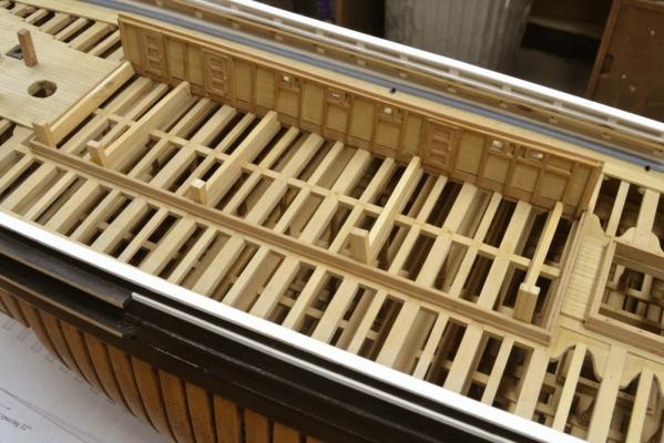
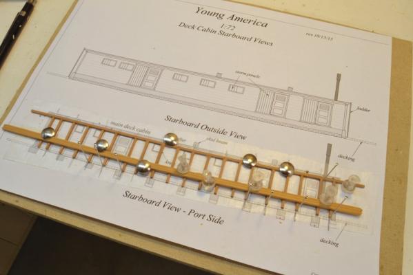
Young America - extreme clipper 1853 Part 119 – Main Deck Cabin 1 It has been quite a while since my last posting to this log in April. Work on the book, drafting for the next phases, and taking the 1:96 POB version to a more complete state has filled the intervening time. I had decided to leave both models at the level of completion covered in Volume I of the book for display at the NRG conference. Work on the 1:72 framed model has now resumed – I hope in earnest. I started fabrication work on the main deck cabin in August and some of that work is shown below. This large cabin housed the crew, the galley, and perhaps other things. Boats were stored on skid beams on the roof. I will be the first to admit that this finicky, small-piece, detail work is not my forte. I am much more at home with beams, clamps and futtocks, but I will describe the method. The first picture shows wall panels for the ends of the cabin. These were made by edge gluing planks that had the outer edges beveled – to simulate lapped planking. The pieces were glued up on waxed paper, with the first plank curved against pins to match the round-up of the deck. The panels were run through the thickness sander to remove excess glue on the inside. They have a first coat of white paint on the outside. These two have been drilled at the widow openings. In the next picture these openings are been cut square. After marking out, this work was started with a chisel and finished off with a flat file. The next picture shows the two panels painted and with the window framing and inside structural members installed. Lacking specific original detail, I framed the cabin much like a house, but with heavier members – 4x4 studs capped by a long 4x4 plate to support the 4x10 beams with knees that will be added later. I found examples of this type of construction in later wooden vessels. I had to decide whether to enclose the cabin completely or leave some of it open to reveal the deck framing below. I decided on the latter course, leaving out internal detail that would further hide the structure below. The next picture shows work on the long, starboard side wall. On all of these wall panels, the siding was painted before installing the trim. In the picture, door openings were cut out and filled with panels that would eventually be trimmed out with small pieces to simulate doors. The next picture shows inside framing on this panel. The 4x4 studs are left long at the bottom to “bolt” into the base coaming. The next picture shows the finished wall panel. The panel for this wall was made to match the curve of the deck sheer by curving the planks as they were edge glued. Door jambs, paneling and simple hardware were added to the base panel shown above. All of the windows and doors are fitted with sliding storm panels that could be closed for protection in heavy weather. Paint was scraped from under these details to ensure good glue joints. In the next picture the side wall is clamped in position and the forward end panel is being fitted for size. The next picture shows the side wall being glued in place to the coaming. The wall is being held in position using pine wedges to force wood strips against the feet of the studs. The last picture shows the port side wall framing being assembled - studs and plate only at this stage. This structure will be left open on the port side. It will be very fragile until all of the framing is added. The heavy timber across the bottom is temporary and has been added to support the structure until installed. It is held to the studs using the paste stick-glue that I use on patterns. To be continued…. Ed


- 3,618 replies
-
- 37
-
-
- young america
- clipper
- (and 1 more)
-
Your choice, Steve, but I believe you are over-complicating the issue. Smaller sheets are very easy to paste down and replace as needed. I used this method for Naiad and both Young America models with great success - and by the method described I can vouch for precision. Ed
- 3,618 replies
-
- 2
-
-
- young america
- clipper
- (and 1 more)
-
Steve, you should read the pdf document included on the CD with instructions to print this drawing on multiple letter-sized sheets - 8 1/2" x 11". Your 8600 Pro will print these sheets and all other CD content on letter-sized paper without a problem. There will be no problem with accuracy of dimensions on the drawings if you print them at actual 100% size then trim and align them properly on the board . I have done this dozens of times without problems. Selecting "Cut Marks" on the Adobe Reader dialog box, crop marks will be printed to facilitate trimming and alignment. Take care when aligning and gluing down these sheets. I know there is an urge to jump in and start the work, but let me suggest reading through the material in order first - both the text and relevant material on the CD. All is thoroughly explained. This will save lots of confusion. Good Luck. Ed
- 3,618 replies
-
- 4
-
-
- young america
- clipper
- (and 1 more)
-
Hello Steve, Thank you for purchasing the book and for your interest in building one of the two models. Let me know how you progress with this. You are not missing any drawings. Drawings 2 and 8 are the plans that get pasted to the shipway for the 1:72 and 1:96 models respectively. Because these tend to get damaged in this service, we decided to include them as pdf files on the CD that could be reprinted and replaced as needed. You will find them - and all information included on the CD - in the subdirectories for the chapters in which they are first needed. The CD also includes instructions on how to print these out on multiple smaller sheets and how to fit them to the shipway. This is the method I have used for all the drawings in my workshop. In the case of the shipway plans (2 and 8) I removed and replaced these a number of times as the work progressed. Just be sure to trim and line up the edges correctly - and of course to print them and all the CD conteent at actual, 100%, size. Good luck. Let me know if you have problems. Ed
- 3,618 replies
-
- 6
-
-
- young america
- clipper
- (and 1 more)
-
I'd like to thank everyone here who participated in the NRG conference in Mystic and who offered kind comments on the models and took interest in them. I was delighted to meet some of you who follow this and the other Young America blog. The models are now safely returned to their berths and ready for the next construction efforts. Again, thanks for your responses to the model - and the book! Ed
- 191 replies
-
- 6
-
-
- young america
- clipper
- (and 1 more)
-
Lovely work on the capstan and pall ring, E&T. Ed
- 346 replies
-
- 2
-
-
- terror
- polar exploration
- (and 2 more)
-
I believe there is some confusion here, Rob. Crothers drawings are not in error and are consistent with the photos and other original data. I have used them in drafting my drawings. I believe the sketch you posted - not Bill Crothers drawing - is in error or of a different ship and that could be confusing for those following this blog. Ed
- 191 replies
-
- 4
-
-
- young america
- clipper
- (and 1 more)
-
I see a lot of comments about securing knots, but most rigging connections are splices over thimbles or eyes, or to make strops with thimbles for blocks. Making splices in model rope is practical only for large sizes. In my experience making splices in small line sizes requires some form of glue. If the material is synthetic, PVA glue is unlikely to hold very well. I like the idea of pH neutral PVA mentioned above and was shocked - shocked at the 3 pH of PVA mentioned above. I used CA extensively on my Victory model - hating every minute of it by the way. I am still waiting to see ill effects - after7 years none yet - an admittedly short period. I found it especially good in making simulated eyes with thimbles as it stiffens the eye and keeps it round. However, based on continued warnings from modelers, for my next rigging project - a big one - I do not expect to use CA and hope to use all natural materials for lines - linen and long staple cotton. I particularly appreciate the mention of pH neutral PVA and will look into it. Later: found neutral pH PVA on Amazon. Ed
-
Hmmm. Interesting response to my criticism of the drawings Rob presented. I guess I will stand by my comments regardless of speculation about various changes that were possible or may have been made. While there is a record of changes made to the rig and of damages and repairs resulting from two incidents at sea, there are no reports of major structural repair or changes. Throughout the project, and especially after the decision to write the book, I made every effort to to stick to what was known about the ship from original sources. I wanted to avoid challenges to the authenticity of the drawings or the model. The purchasers, readers and those who decide to build the model deserve no less. In a project that will take an effort of four or five years, I also owed that to myself. Fortunately, we have the exhaustive work of Bill Crothers. Meeting Bill, discussing his research, understanding his meticulous attention to detail and backtracking through some of his sources convinced me I was in good hands. Some speculation was definitely required. Much of this was on minor, inconsequential detail, but there were cases where I needed to speculate on structural design. For example, I had to decide between some different approaches to framing the eliptical stern. The method I chose is typical and probable, but not documented. For this reason I planked over this intricate work so any claims about its authenticity would not detract from the model. There were other similar cases. Even with this level of care, I expect there will be issues. I will be concerned only by those that arise from original sources and take Bill's good advice on all others that "no one can prove you wrong." Greg, I appreciate your questions on how far to take the demo model. As I hope you will see, I continued to work beyond what is shown in these last posts to include deck planking and facilities to almost the same point as the framed model - the state covered in Volume I of the book. Both models are now at about that point. While I do not intend to take the POB model any further, it has been a temptation. At times I have wondered if that is the model I should rig. However, as this model started out purely to demo the POB framing method - without expectation of producing a quality finished model - I must confess to not always taking the care I took with the framed version. If you see the model, this may be apparent. So, the plan is to continue on with the 1:72 framed model. I hasten to add, however, that Volume II will cover the masting and rigging for either version equally and that the POB version would be a very attractive fully-rigged alternative. At 1:96 it will also consume less space. Ed
- 191 replies
-
- 11
-
-
- young america
- clipper
- (and 1 more)
-
Rob, I meant to comment on the last pictures you posted, but keep forgetting. The two photographs are well known and have been posted on this blog before. I believe the first - of the port side from forward - was actually taken in New York. A very excellent print of this can be found in the book, William Webb, Shipbuilder by Dunbaugh and Thomas. The dates on these pictures are unknown, but they do show double topsails that were fitted in 1854. The pictures are much later, however, since they also show pole masts for the t'gallants and above. The dates for these are unknown. I think the pictures probably date in the late 1860s/eqarly 1870s. They offer a wealth of information depending on the quality of the image. The ones you posted are pretty good. Bill Crothers had access to the actual photos and based much of his drawing detail on those. I actually have photos from his files. I appreciate your posting of the image showing poop and forecastle but have some doubts about it. The drawing clearly shows riveted iron plates and YA was, of course, wood. There are also some other details that, to me at least are questionable. The stern view shows stern davits which do not show in any reference. Also, the stern monkey rail shows turned wood posts and rail that differ from the brass rail shown in the pictures. It is also clear from the pictures that the poop deck is at the level of the top capping rail (the fancy rail) at the stern and not below it as shown in the sketch. There is a large opening through the hull below the poop for the aft mooring lines. This differs from the mooring bitt location on either side of the boomkins shown in the second photo. Finally, the coach into the cabin deck appears very abbreviated in the fore and aft direction, leaving no room for a necessary main deck vestibule and has the entrance doors on the forward bulkhead as opposed to side entries. Windows (vs. doors) can actually be seen on the forward bulkhead in one of the photos. The view of the forecastle is closer to the mark but the topgallant rail seems too high and extends aft past the catheads. Also, there is no samson post to mount the heavers for the windlass below. More space between the ladderways would also be necessary to make room for operation of the windlass from the fcsle. Same comments on bulwark openings for the mooring lines. There are no mooring bitt openings on either photo. While I appreciate your posting of this information, I only mention all this so that those wanting to build the model from the book are not confused by these discrepancies. I suspect that these drawings are either speculative, typical of the time, or of another ship. To me, the iron plates are a tipoff. There are many unknowns in the actual construction and also the possibility of minor (non-structural) modifications. Some speculation is always necessary to fill in unknown details. Where authentic documentation is available (like the photos), I believe it should be paramount. So, caution is necessary. Ed
- 191 replies
-
- 4
-
-
- young america
- clipper
- (and 1 more)
-
Thanks, everyone. Rudolf, the curved planking around and under the stern is well above the metal sheathing so it will be visible. Painting will cover most of the planking joint detail. Bending these planks around the stern requires straight-grained, flexible wood plus a lot of boiling and then drying time. After that there will still be trimming to do so I suggest starting with slightly oversized planks (say plus one inch or so. Good luck. Ed
- 191 replies
-
- 5
-
-
- young america
- clipper
- (and 1 more)
-
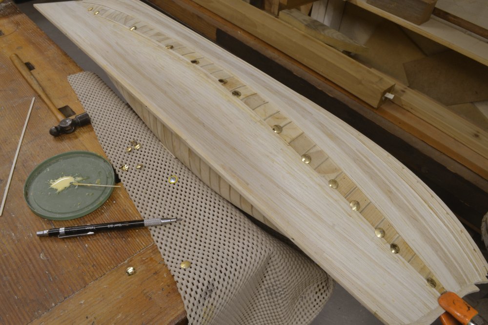
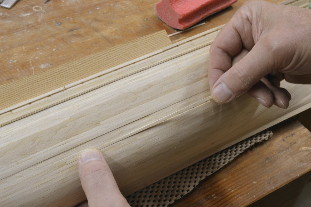
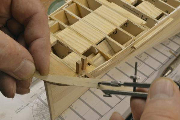
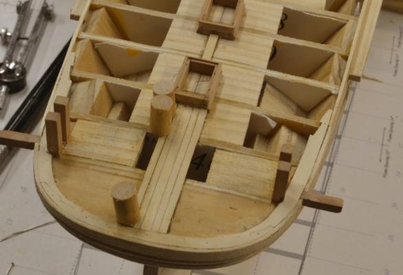
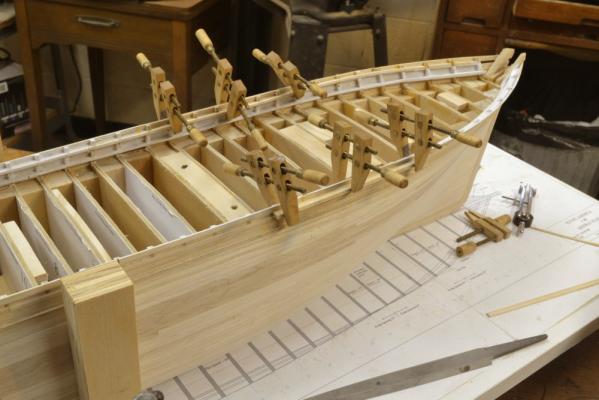
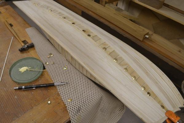
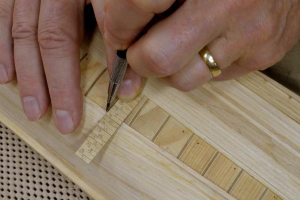
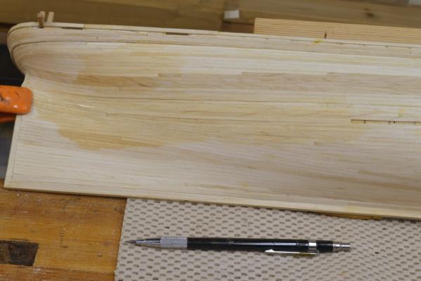
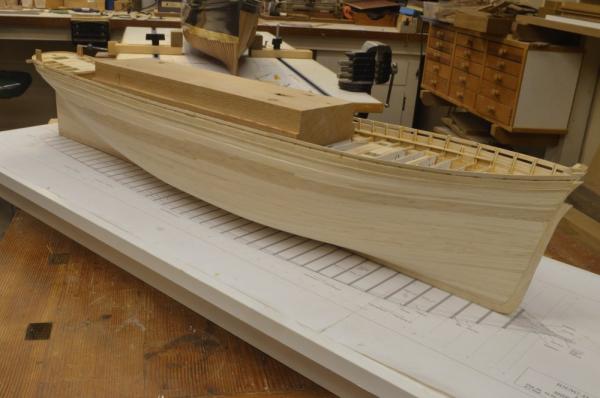
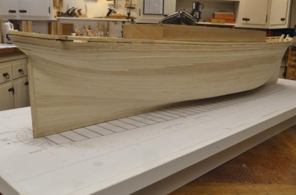
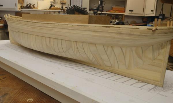
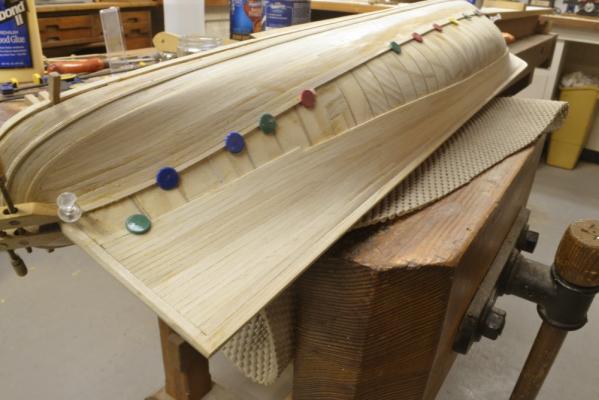
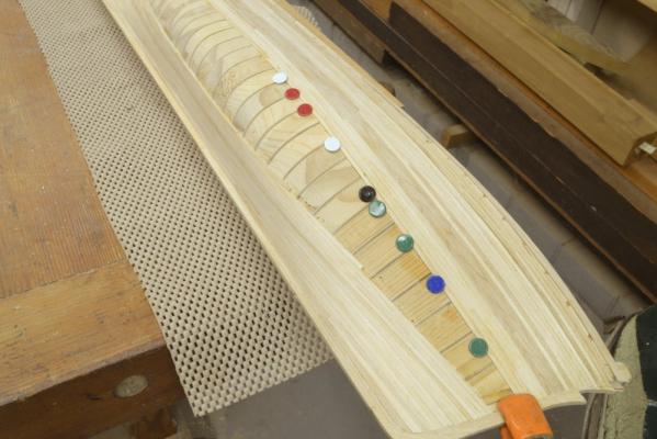
Young America 1853 – POB 1:96 Part 27 – Completing the Lower Hull Planking Installing all this 6-7” wide planking over the entire hull – at least on the starboard side – was a long slog, but I did enjoyed seeing it progress to completion. In the first picture, the unplanked area is shrinking. At this stage the focus was on taking it to the point where one last full-sized plank would just fit into the remaining space left for it to complete the job. Getting that last space to come out to a 7” opening with parallel sides involved some planning in the placement of the dropped strakes that were necessary both fore and aft. The next picture shows the method I used for setting points where dropped strakes butt into the previous plank. I prefer to mark these on the actual work based on the as-built situation rather than try to draft complex planking plans. The method I use is thoroughly described in the book, so I will only summarize it here. In the picture a gauge is being used to mark the point where just enough room is available for some number of full-width planks. This gauge was made by gluing strips of plank to a slip of paper. The strip was slid along the opening until one of the lines coincided with the edge of the installed planking. At these points two strakes will become the width of one – by notching the installed strake on a taper back to the last point and tapering the new plank to fit. All of these points were marked then later re-marked to make any readjustments as planks were installed. This is a simple process that works very well. I used it on my Victory model, Naiad and both Young America versions – for internal and external plank. In the next picture the gap is narrowing further and the placement of dropped strakes is becoming more critical. In the picture the narrow space to the left will just accommodate one strake with a taper to half width at the forward end of the opening. The next picture shows the space left for the last plank at the stern. At this stage I was regretting using some slightly darker maple for some of the planks - even though all is intended to be painted. In the next picture this plank has been installed and all that remains is the closing piece near midship. In the next picture that piece is being pressed down into place in a tight fit that required no pinning. A little tapping with a hammer helped. Finally, the completed planking of the bottom on the starboard side. And from the stern quarter. The last picture shows the completed lower planking on the port side down to about midway into the wale. There are 21 strakes of 6” wale planking on the ship. The lower part of the hull was left unplanked on this side to show the method of POB framing used. Even though this model initially started out as a demo of the POB framing only, I got a lot of satisfaction in taking it to this further-than-intended stage and eventually went a bit further. Next step was to install the channels…..next time. Ed

- 191 replies
-
- 26
-
-
- young america
- clipper
- (and 1 more)
-
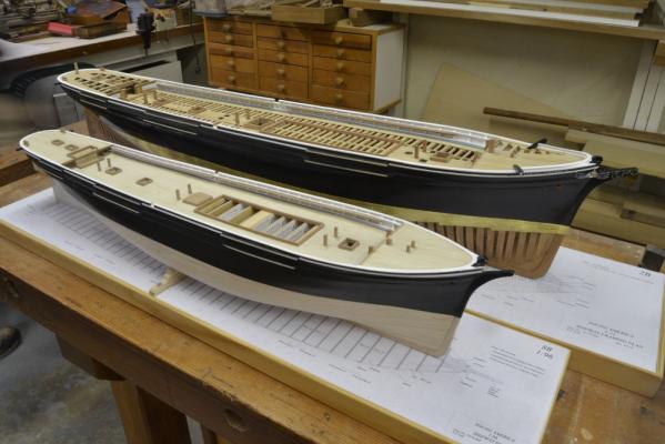
Thank you all for your comments and likes and for your support for the now-published book. I feel I have been neglecting the fully-framed version of Young America - and posting to this blog - for way to long. There has been little work on the model since April - a long hiatus. May and June were taken up with getting the book ready for press. Since then I have been consumed with the drafting and research for the next phases of construction - fitting out the weather decks and rigging. I also decided to carry the POB version of the model to a more advanced state and post that work on MSW to supplement to POB Chapters in the book for those who might want to build that model these posts will provide more information than could be included in Volume I. Volume II will apply to both versions equally - but it is some time off. The picture below shows the current state of both models - mounted on temporary bases and ready for transport to the NRG Conference in Mystic next week. Hope to see many of you there. Ed
- 3,618 replies
-
- 38
-
-
- young america
- clipper
- (and 1 more)
-
I love the painting, Rob. There are so few of Young America. I had not seen this one before but will look it up. Thanks for posting. Ed
- 191 replies
-
- 3
-
-
- young america
- clipper
- (and 1 more)
-
Marc, Steel(1794) states that clue cringles are wormed parcelled and served, with the worming being done as the cringles are spliced. Kipping (14th edition 1898) indicates likewise, but offers specifics to merchant as opposed to Navy practice. Kipping can be found at the following link. You may find this helpful. As I have read it only superficially, I will not attempt to interpret. Kipping also discusses iron clues cringles. https://books.google.com/books/about/The_elements_of_sailmaking.html?id=3n8EAAAAQAAJ Ed
-
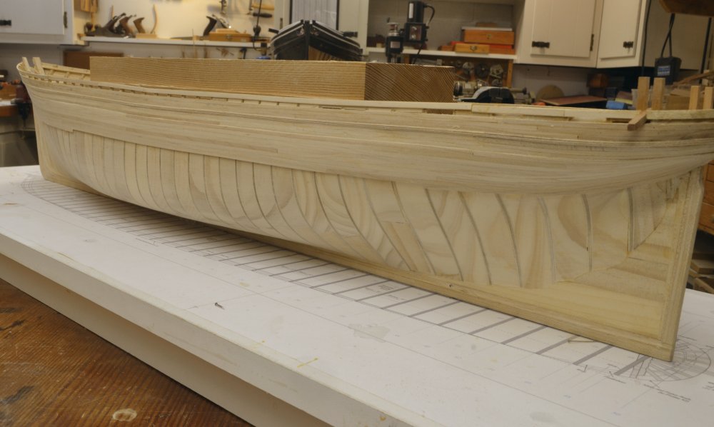
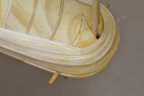
Young America 1853 – POB 1:96 Part 26 – Hull Planking continued With the completion of the curved strakes around the stern, planking of the hull continued downward – or upward in the pictures of the inverted hull. This planking again begins at the stern, but after the fourth curved strake, further planking butts into this strake. The point where this occurs is called the “knuckle” of the counter. This mysterious term and the line it describes will be seen on the drawings. At this break point on the original ship, a transom was fitted to bed the ends of the planks. This can be seen on the framed model, but on the POB version it is incorporated into the solid stern block. The first picture shows the first two butted planks on the starboard side. Because the first several of these planks intersect the curved planks at an acute angle, they are “cut in” to the last curved plank to avoid a sharp tapered edge that could not have been caulked. This cutting into the last curved strake is shown in the next picture. The planks should enter the joint in a fair line with their ends tapered down to about half width to fit into the cutout. These cutouts are made by first marking the point where the plank will end, then plunge-cutting perpendicular to the plank with a sharp chisel to start the joint. The edge along the plank is then pared out in a fair line as shown in the above picture. Note the thickness of these planks. The last two curved planks are the upper planks of the 6” thick wale and are therefore heavier. The next photo shows the butted strake being fit into the joint. Additional butted planks continued to be added. When the ends of the butts reached an angle of 45 degrees or so, cutting in is eliminated and the ends simply butted into the last curved strake. In the next picture this planking has reached the sternpost and the sternpost rabbet is being trimmed at the top to allow the next planks to be seated into it. The next picture shows the first plank being fitted into the rabbet. Some curving was necessary as can be seen. The next picture shows wale planking proceeding downward and the status of the planking from the bottom. The last picture shows progress at the bow. Fitting the “hooding ends” of the planks into the stem rabbet was simpler than the work at the stern. A heavy clamp was used to make sure these ends were held well into the rabbet and tight against their neighbors. This picture shows that a lot of strake dropping and use of stealers will be needed as the forward (and aft) ends of the hull approach. Completing this planking will be shown in the next post. One may ask, if the model will be painted, why go through all of this authentic, complex joinery. You will recall that earlier in these posts I mentioned that this version of the model was intended for beginning builders, but that as a learning device, practices that would be necessary in full-framed modeling would be introduced to provide some practice with those methods. That has been the reason for a number of the methods used on this version. I hope this will prove helpful. Ed


- 191 replies
-
- 17
-
-
- young america
- clipper
- (and 1 more)
-
HMS Naiad 1797 by albert - FINISHED - 1/48
EdT replied to albert's topic in - Build logs for subjects built 1751 - 1800
Great looking work, Albert, as always. Ed -
David, thanks for your question. I guess the simple answer is that I have a lot of hard maple left over from past furniture projects, so partly it was a matter of convenience. I have not used beech much and do not have any lying around. Apart from the ready supply, maple does very well for the purpose - its hard, sands well and takes a good finish. I would say that except for the flecked grain, it is an ideal model wood.
- 191 replies
-
- 6
-
-
- young america
- clipper
- (and 1 more)
-
Jan, The Jorgenson style screw clamps are home made. A detailed drawing and instructions for making these are included in The Naiad Frigate, Volume I. Also included is information to make a simpler version of the clamps. I have used both types for years and find them indispensible. Ed
- 191 replies
-
- 5
-
-
- young america
- clipper
- (and 1 more)