HOLIDAY DONATION DRIVE - SUPPORT MSW - DO YOUR PART TO KEEP THIS GREAT FORUM GOING! (89 donations so far out of 49,000 members - C'mon guys!)
×


EdT
-
Posts
2,214 -
Joined
-
Last visited
Content Type
Profiles
Forums
Gallery
Events
Everything posted by EdT
-
Micheal, I guess if I wanted to cast parts I would use pewter. Investment casting doesn't seem to be the right answer. The casting equipment I have could easily handle a large number (dozens depending on size) of parts per pour and with the right RTV rubber, mold life would not be a problem with pewter. I have never blackened pewter but there seem to be many products out there. The other issue is that for the books, I want to use methods that other modelers can reasonably adopt. I wouldn't like to suggest that people acquire a vacuum degassing chamber and centrifugal casting machine to make shackles or jackstay stanchions. Without spinning, casting just a few of these at a time would be extra tedious, and without vacuum I think you would be in for drilling a lot of mold bubbles out of eyebolts. Casting is an interesting option though, and deserves some thought - especially in the absence of a good process for some of these parts. Thanks for the thought. Ed
- 3,618 replies
-
- 5
-

-
- young america
- clipper
- (and 1 more)
-
I don't know, Micheal. Seems like a lot of work for the two flywheels. You would still have to make one pattern. I've done quite a lot of small pattern and moldmaking for casting of lo-melt alloys in RTV, but have never done any lost wax. Is this something that could be practically done in the home shop, or would the brass casting likely have to be farmed out. I am interested because there are quite a lot of metal parts to be made where large runs may be appropriate for example shackles, jackstay stanchions, perhaps yard trusses. Open to suggestions. Hello, Richard. There was actually a fair bit of ironwork on Naiad - a lot of iron knees, about half of which were photo-etched triangular plate knees and the rest iron bracket type. These were also the deadeye chains, some ironwork on the capstan pawl rings, what else?? Virtually all were copper. Ed
- 3,618 replies
-
- 4
-
-
- young america
- clipper
- (and 1 more)
-
I love the precison, Micheal. Bravo! Plenty of food for thought in your posts as I contemplate YA's boats. Ed
-
Thank you all for the comments and likes. You are right, Frank. The Cad drawing helped a lot in determining precise dimensions and angles. While this could be done by hand, the CAD features provide better precision. Getting the disk to be flush with the ends of the chuck jaws was quite easy. First the disk was laid on a flat surface and the detached chuck placed over it. As the jaws were tightened the disk was held down with a dowel through the hole in the chuck. The chuck was then inverted, the fit checked with a straightedge and the jaws tightened further. Greg, the problem with making these in multiple parts is assuring concentricity of the assembly in something this small, to say nothing of the challenge of aligning the parts for soldering. I never considered anything but making the wheels from one piece. The piece was held quite adequately in the chuck as shown, and as will be further shown in the next post. I was concerned about this as well, so after tightening the jaws carefully, I took the precaution of taking very light cuts with a slow feed. This worked fine. Ed
- 3,618 replies
-
- 13
-
-
- young america
- clipper
- (and 1 more)
-
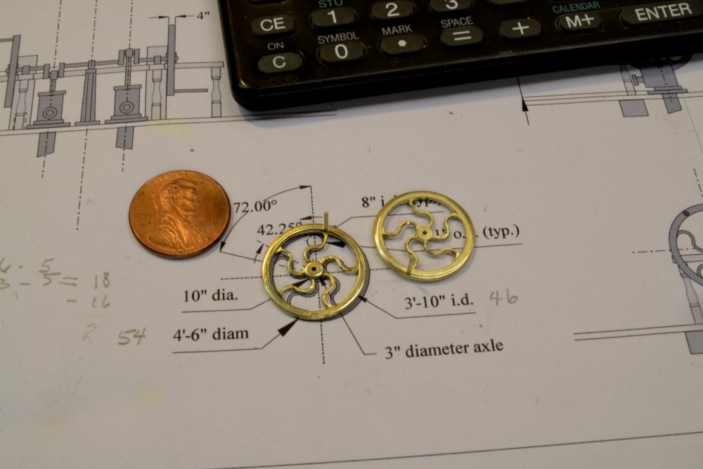
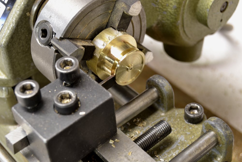
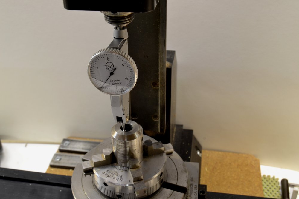
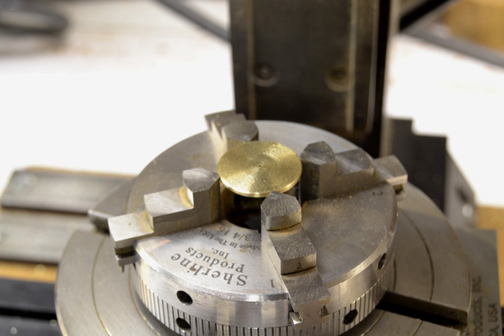
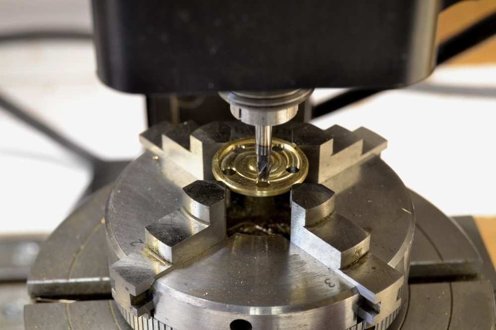
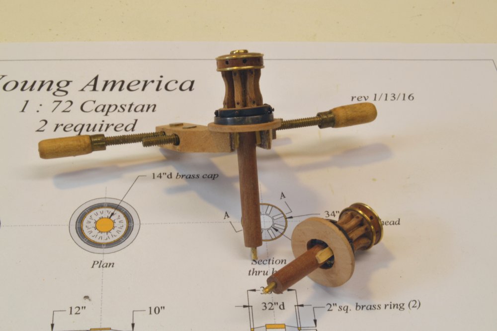
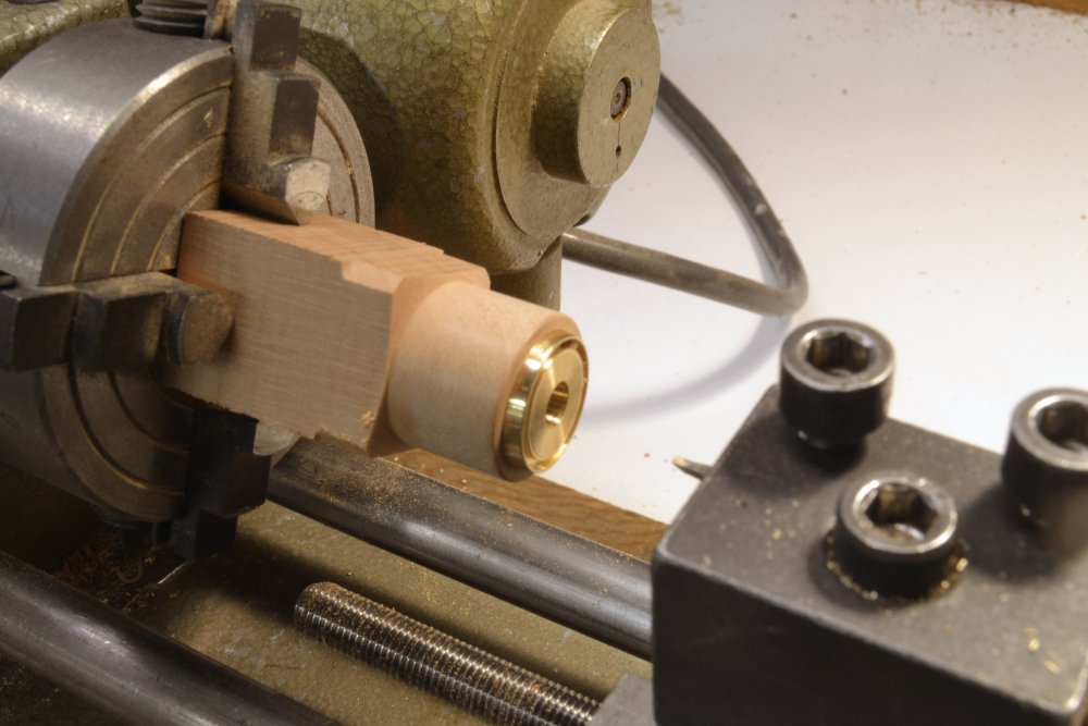
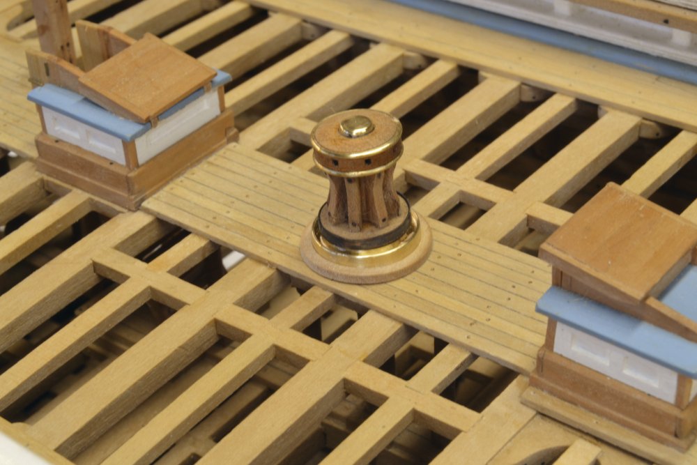
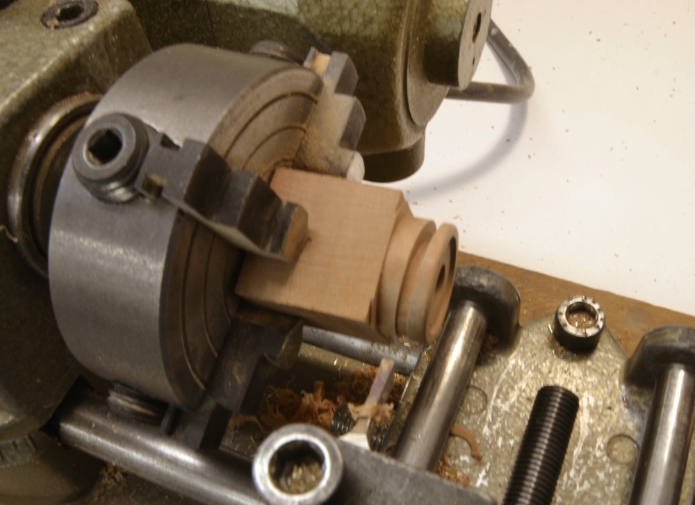
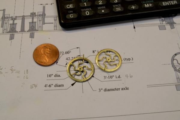
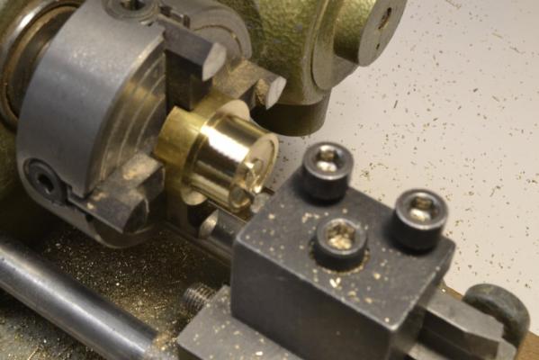
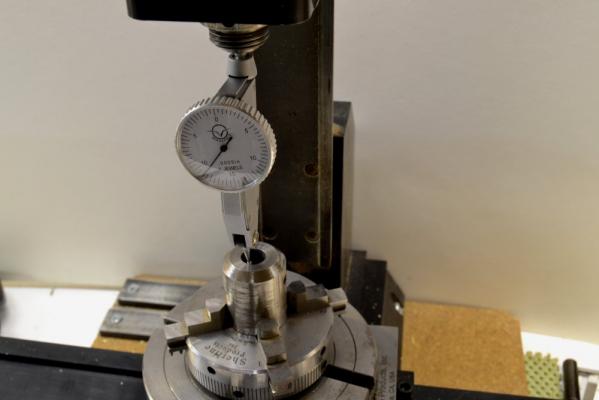
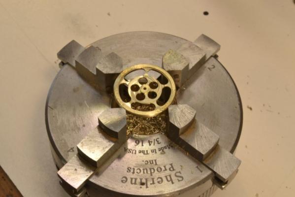
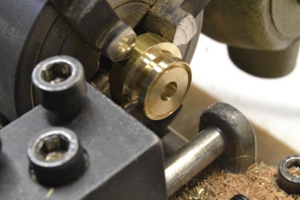
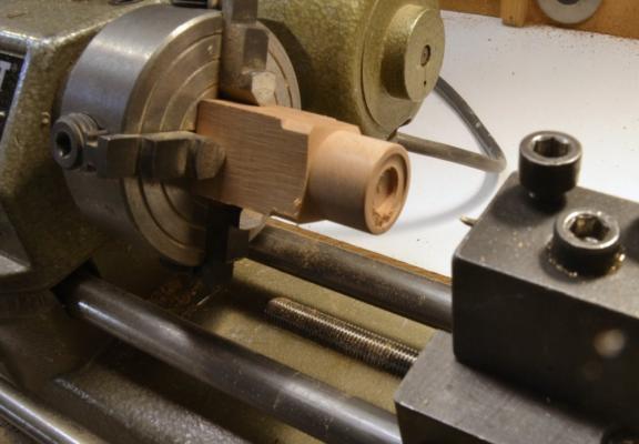
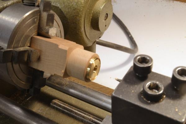
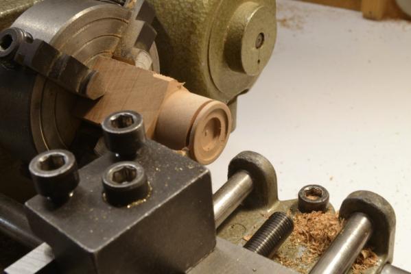
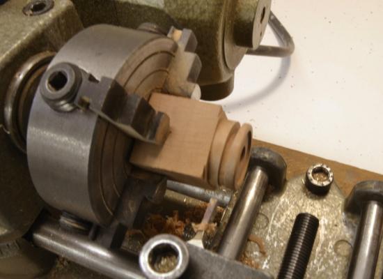
Young America - extreme clipper 1853 Part 139 – Bilge Pumps 3 The twin pump flywheels were arguably the most beautiful feature on the entire deck with their graceful, s-shaped spokes. The wheels, almost finished and ready for mounting are shown in the first picture. As can be seen from the underlying drawing in this picture, the wheels are 4’6” in diameter. The momentum created when rotating these large heavy wheels greatly assisted in the manual pumping effort. Pumping could be done with one or two men on each side. The curved spokes were more than decorative. Their purpose was to yield to the shrinking stresses created when the castings cooled – avoiding fractures. I have been puzzling about how to make these for quite a while, considering the complexity of the spokes and the importance of symmetry in the final pieces. They were made in two phases. The first, described in this posting, used machines – including the most important (and most used) of those shown at the top of the above picture. Because all of my drawings show real world dimensions, scale equivalents had to be constantly calculated for machining adjustments. The drawings were tailored and dimensioned to support the machining process requirements. The second phase was done by hand and will be covered in Part 140. The next picture shows a 1” diameter brass bar chucked in the lathe in the first machining step. In this picture the piece has been centered, faced off square, center-drilled, drilled for the shaft and turned to the final diameter of 54” (3/4” at 1:72). The wheel is 4” thick overall with a 4” x 4” rim. In the picture the recessed spoke area is being cut out at a depth of 1” (.014” at 1:72) – from the inside of the rim to the axle hub, to allow for the final 2” thickness of the spokes. In the next picture, the wheel disk is being parted off. The remaining machine work on the piece was done on the mill. For this work the rotating table had to be very precisely centered on the spindle so all the cuts would be concentric with the original turning. This centering is shown in progress in the next picture with the aid of the dial indicator. I used a 3/8” milling bit holder chucked in the four-jawed self-centering chuck for this. The dial indicator is chucked in a spindle collet so it can be rotated. The small size of the Sherline mill sometimes requires ingenuity in coming up with dial indicator mounts. The bit holder is precisely concentric and worked well for this. After alignment, both x and y axes on the mill were locked to prevent accidental movement. The wheel disk was then placed in the chuck as shown below. The face recessed in the lathe is downward. The surface of the disk is set precisely flush with the ends of the jaws. The first machining steps have been completed in the next picture. I designed the wheel to have an inside radius of 8” on each arc of the spokes and a spoke width of 2”. This required a special end mill. The one shown is .110” diameter (7.92”) - close enough. All the milling was then done by adjusting the y-table calibration wheels – after loosening the stop. After facing off the 1” recess, five holes through the spoke area were made at 72 degrees apart and flush with the inside of the rim as shown above. Next, the cutter was moved in by 10” (.139”) and holes were bored on the same radius as the outer holes – flush with the axle hub. These holes are shown below after one more final machining step. In this last step, the bit was returned to the outer position over one of the outer holes. It was then lowered and the table rotated 42 degrees to remove material between spokes at the rim. In the picture this work has been done and the chuck – with the piece unmoved – has been removed from the machine. So far, so good. The remaining hand work on the wheel will be described in the next part. Ed


- 3,618 replies
-
- 32
-
-
- young america
- clipper
- (and 1 more)
-
Thanks again everyone. Frank the soldering table is not an inexpensive tool and not an absolute must, but very useful and I think reasonably priced for the quality. Bob, here is the link to the product page on the Contenti website: https://contenti.com/soldering-n-joining/soldering-tools/soldering-boards/rotary-soldering-table Ed
- 3,618 replies
-
- 6
-
-
- young america
- clipper
- (and 1 more)
-
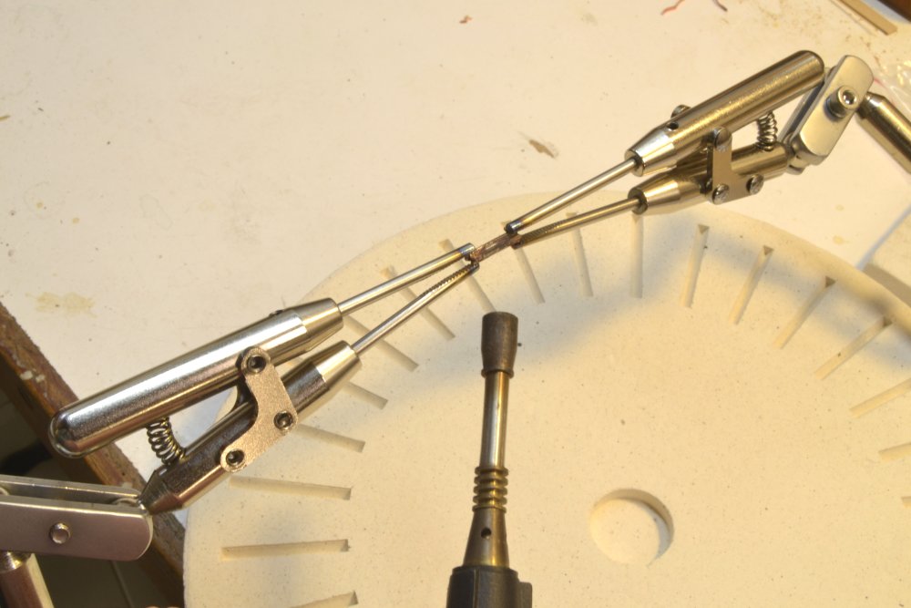
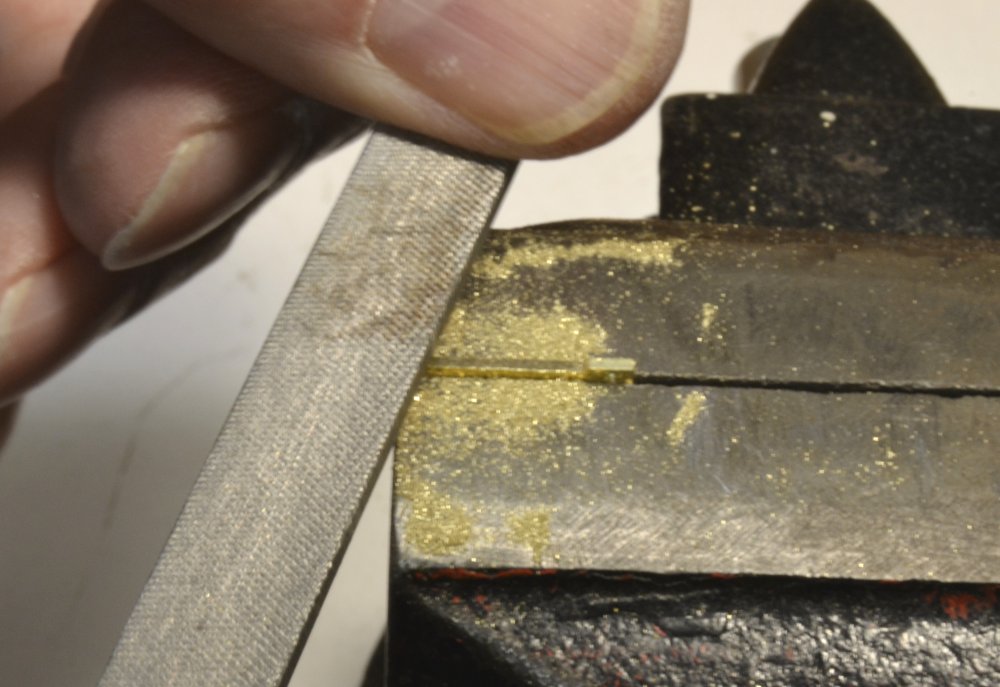
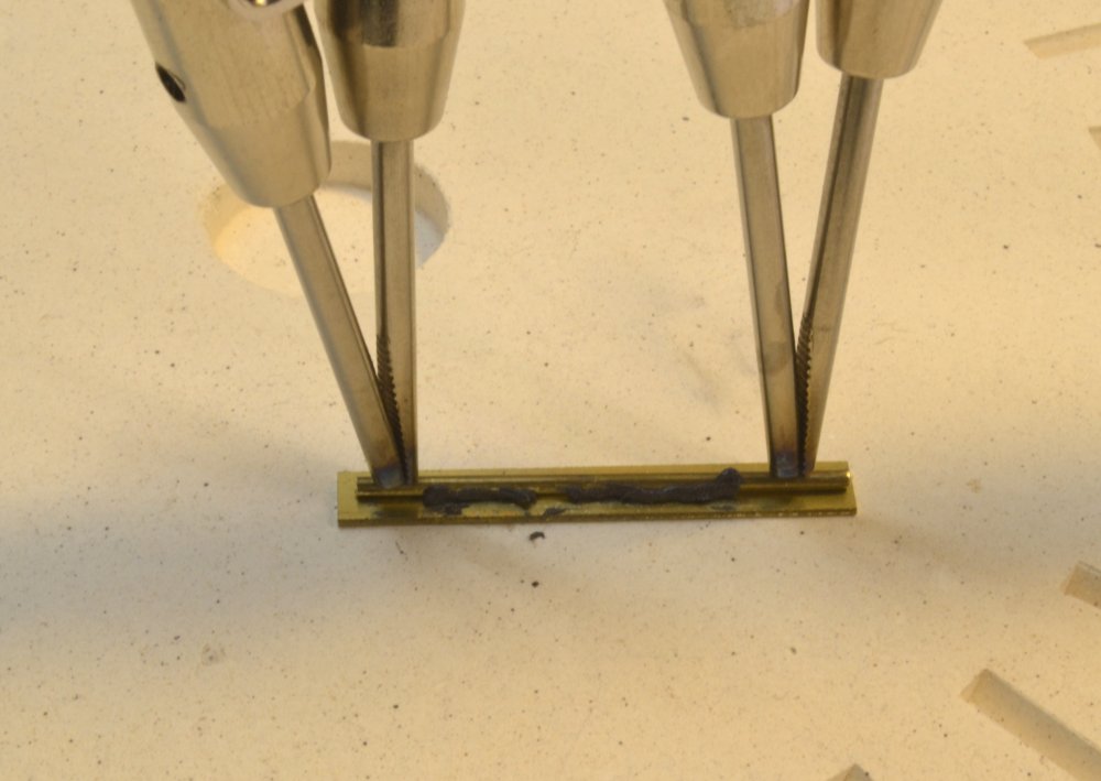
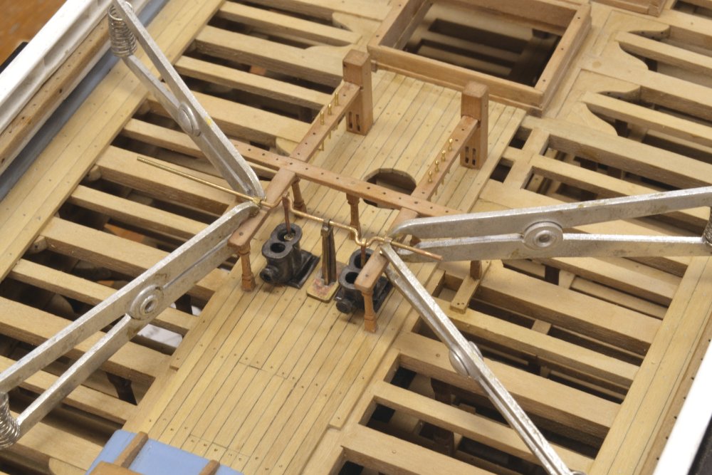
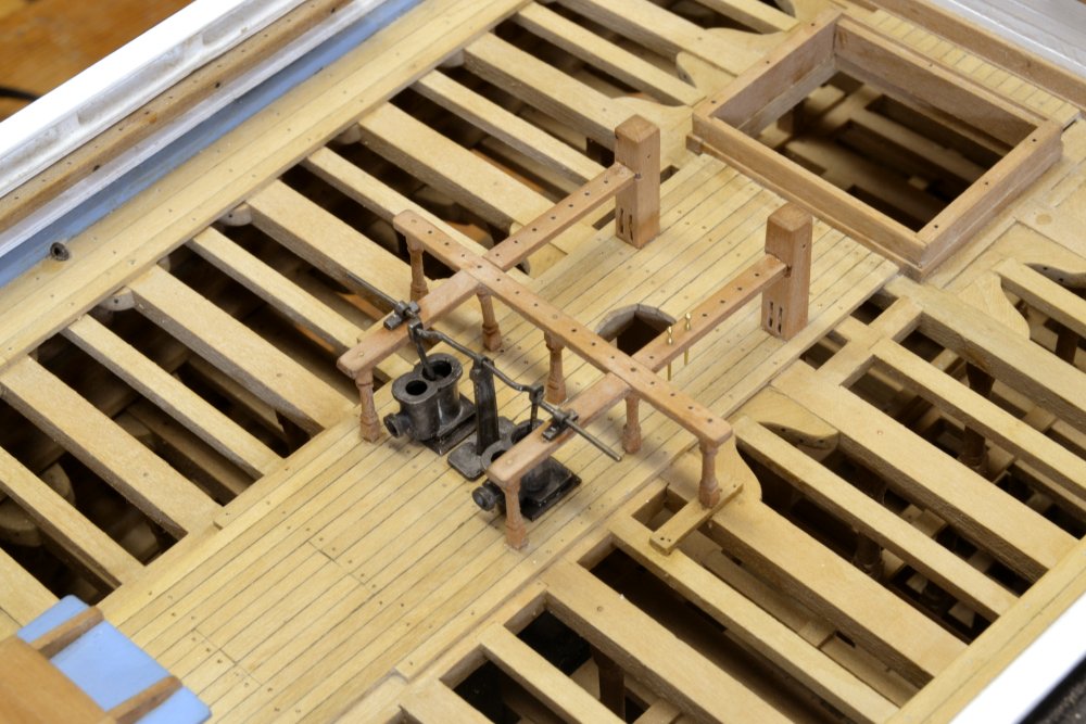
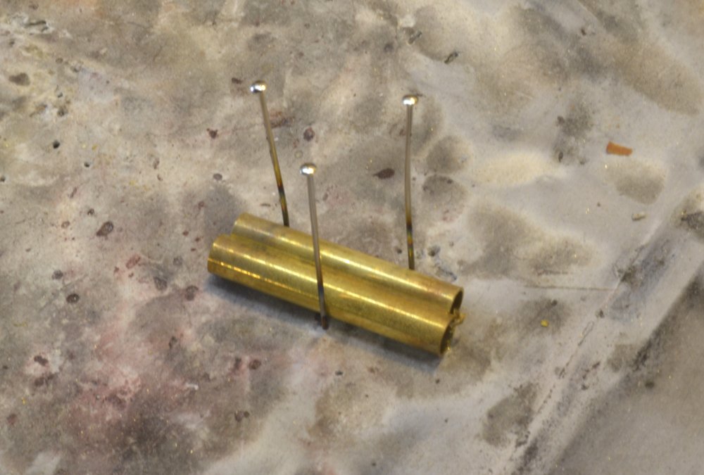
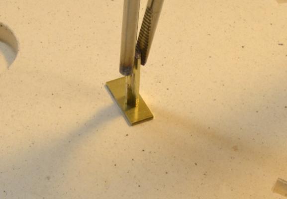
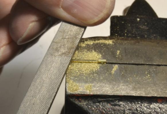
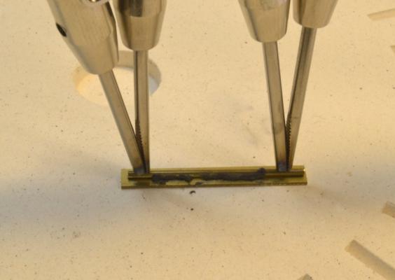
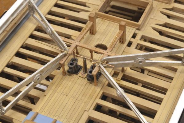
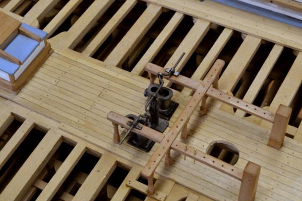
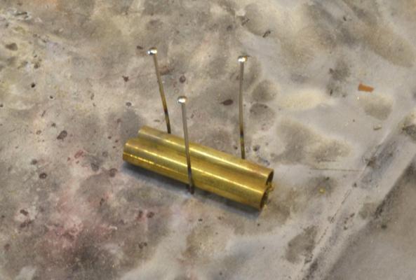
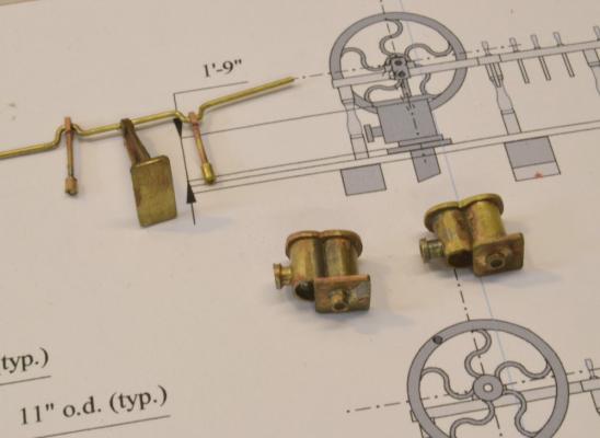
Young America - extreme clipper 1853 Part 138 – Bilge Pumps 2 The next task on the pumps was to make the crankshaft/connecting rod assembly shown in the last picture in the last posting. This included the central supporting bearing pillar shown in that picture. That part was made first - as a tapered pier with vertical gusset supports in an X pattern. This provided an opportunity to use one of my new Christmas toys shown in the next few pictures. In the first picture one of the side gusset plates is being silver soldered to the main central plate. The parts are firmly held in place by the two articulating clamps that are mounted on either side of a rotating ceramic base. The clamp arms each have a pair of ball joints that can be tightened to hold the clamps very securely in any position. The clamp rods are tungsten, so there is no problem with heat. Also the stout handles do not heat up, so pieces can be unclamped immediately without risk of burns and the clamp springs are protected from overheating. For someone like me, with my shaky hands, this tool is a godsend – and just in time for the plethora of metalwork coming up. The torch is just a miniature propane torch. Oxy flame temperatures are unnecessary for most of this work. The next picture shows the pier subassembly held down on its baseplate for the next soldering step. Because these assemblies will be blackened, I used Phosphorus-Copper prefluxed solder paste, which seems to blacken easier. It has a melting point of 1325 degrees F – about the same as medium (65%) silver solder. In the next picture one of the connecting rods is being shaped after drilling of the bearing hole in a small piece of brass plate. The connecting rods were then fitted with undersize “pistons” at their bottom ends. These fit very loosely in the pump cylinders to allow easy rotation. I did not attempt an authentic fit with these. There are three pillow block bearings (sometimes called rhodings) that hold the crankshaft – one in the center and one mounted on each fore and aft fife rail. These were made by slicing off individual bearings from the soldered strip shown ready for the torch in the next picture. The bearings are provided by the hole in the brass tube. The crankshaft was formed from a length of .032” (2.5”) brass rod. The connecting rods and center pillar bearing had to be fitted to this before bending. In the next picture the crankshaft assembly is being test fitted to ensure unobstructed rotation. The side bearings are clamped to the fife rails for this. I was very glad at this point that I did not opt for closer fitting pistons. In the last two pictures the crank assembly has been blackened and permanently installed. The central pillar and the two side bearings were cemented in place with thin CA. So far so good. Now it was time to make the two delicately shaped flywheels that I hope will be the eye-attracting features of the pumps. Ed


- 3,618 replies
-
- 42
-
-
- young america
- clipper
- (and 1 more)
-
Lovely work, Christian. This should be an impressive model at 3/8" to a foot. I look forward to seeing you progress. Ed
-
Hi Guy, nice to hear from you. The short answer to your question is yes, all the drawings I use for the model, including those shown in some of the posts are included with the books, either as full sized prints or as letter-sized pdf files that can be printed from the CD. The final drawings may differ slightly from those shown during my builds. I update the drawings to reflect any changes made or errors picked up during my construction. E&T, alchemy barely describes it. Ed
- 3,618 replies
-
- 8
-
-
- young america
- clipper
- (and 1 more)
-
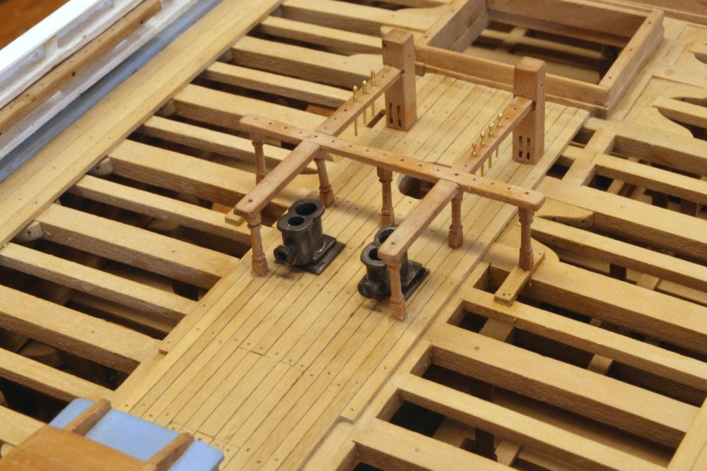
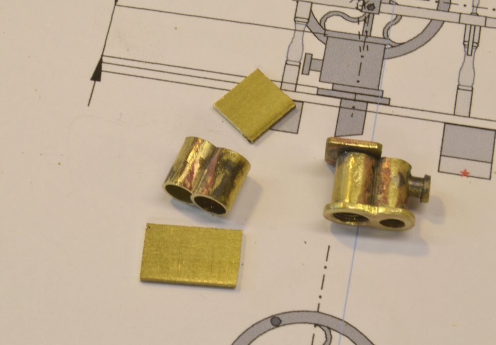
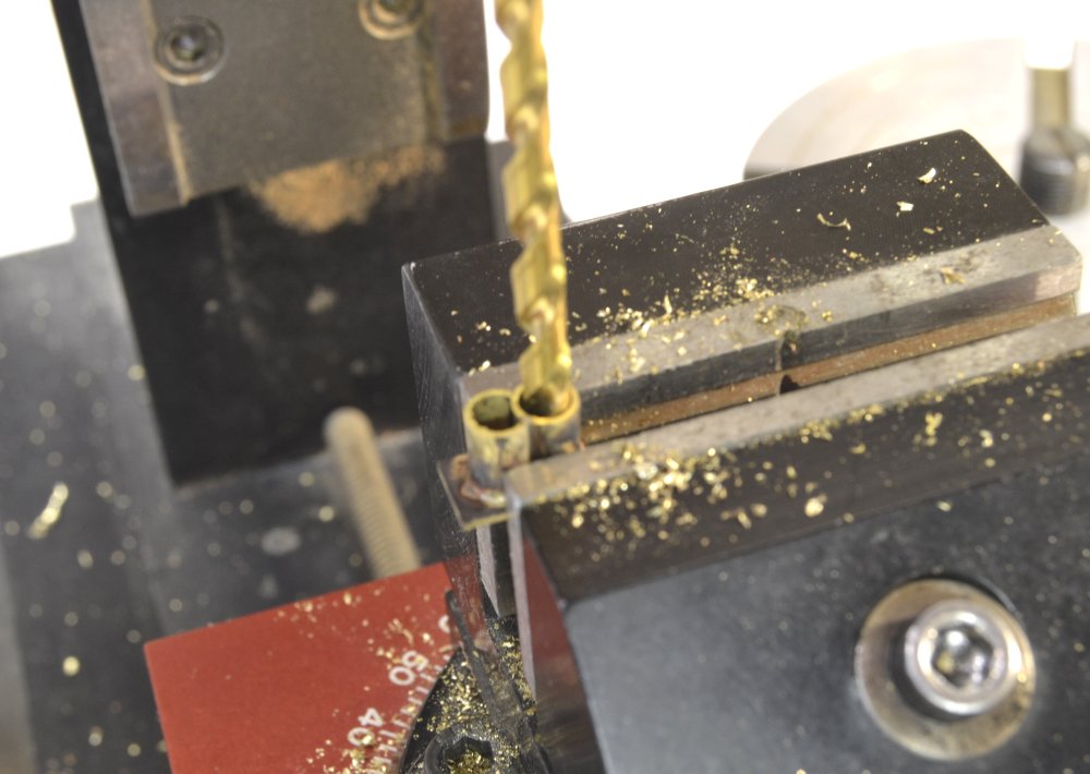
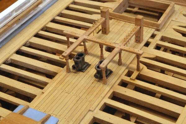
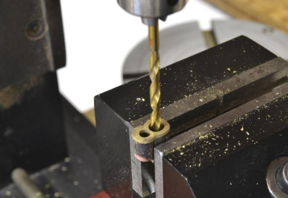
Young America - extreme clipper 1853 Part 137 – Bilge Pumps 1 You may recall from an early post that suction pipes were installed from the limber channel at the garboard strake up to the main deck just aft of the main mast. There, the two pipes were terminated at an iron plate on the deck. Unlike earlier chain pumps that could only pick up water from above the floor frames, reciprocating suction pumps that came into use in the md 19th century could lower their intakes to the underside of the floor frames. This was discussed in earlier posts. The first step in constructing the pumps was to make the two cast iron casings. The completed casings are shown mounted in the first picture. Casings typical of the times – these being only typical of the type and not based on a specific specification – usually consisted of a cylinder to house the piston and a second chamber or reservoir to collect the water and discharge it from the pump. The integral assembly was cast iron. There were two options that I considered for making these. They could be machined from a block or they could be fabricated. I chose the latter approach, using telescoping brass tubes. The first fabrication step is shown below. The main cylinder consists of a brass tube and the secondary reservoir is made from a similar tube that has had a portion sliced off on the circular saw. In the picture the two pieces are shown ready to be soldered together. The next picture shows steps after soldering the two tubes shown above. The soldered pieces were first cut to final height. Rectangular shapes were then soldered top and bottom. The assembly on the right, shown upside down, has had its flanged discharge pipe installed the top rectangle shaped and drilled as shown to be open at the top. The next picture shows the first soldering step with the cylinder assembly held in place on the top plate for soldering. The device and surface shown in this picture is a new tool acquisition that I will discuss in a later post. After the top plate was soldered on, the two top holes were drilled as shown in the next picture. After drilling through from the bottom and soldering on the bottom plate, that plate was then drilled to fit a spigot that would fit into the suction pipes at deck level. In the above picture the top figure eight flange has been roughly shaped. The two finished casings are shown in the next picture prior to final pickling and blackening. Also shown in this picture is the piston/crankshaft assembly. A supporting iron standard with a mounted bearing is shown at the center of the shaft. Work on this assembly will be covered in the next part. Ed


- 3,618 replies
-
- 43
-
-
- young america
- clipper
- (and 1 more)
-
Thanks, everyone for the comments, likes and questions. Crackers, if being professional means earning money, you've got the wrong guy. Harvey, redoing things may be part of the craft. After seeing Remco's Kingfisher wheel, I am entertaining similar thoughts. E&T, I could write a whole book about my frustrations trying to make metal black. The only way I have had consistent success is to use copper and blacken it with liver of sulfur. I have had little problem with that. Brass has been another matter, beginning with cannons I made in the 1970's. Silver soldered joints have been the major problem - either getting them black to begin with or watching white by-products emerge later. I suspected our hard water, but using distilled water didn't make much difference. Pickling is of course essential. I now boil all parts in white vinegar then degrease them before blackening in a dilute solution, either WinOx, Hobby Black, or Birchwood Casey Brass Black (I switch when I get frustrated.) WinOx can be used, like liver of sulfur, next to wood without staining. That does not answer your question, but is background. On the pawl baseplate I used copper-phosphorus silver solder paste from Contenti. I believe it is in the midrange of silver solder melt temperatures. It works well on copper with LOS and can be used on brass. One aid in blackening is to use very tiny amounts of solder. That is where the solder/paste syringe comes in handy, but I usually squeeze some out and apply it to the joint with a toothpick. In spite of all this I cannot boast of consistent results and sometimes, not very often, revert to the old standby, Rustoleum flat black. David, I believe Mark answered your question on liver of sulfur. Also, note that the paste I refer to is not just flux, but a combination of flux and silver solder types. Thanks, again everyone. I hope to have the first post on the blackened brass bilge pumps up shortly and that may provide further fodder to the blackening discussion - and maybe some helpful responses. Ed
- 3,618 replies
-
- 11
-
-
- young america
- clipper
- (and 1 more)
-
Looking forward to following along, Paul. Ed
-
HM Cutter Cheerful 1806 by Erik W - 1:48 scale
EdT replied to Erik W's topic in - Build logs for subjects built 1801 - 1850
Neat work, Erik - and such a clean, tidy work area. This and Druxey's new log make me yearn for something small. Ed -
Well, Druxey, I have just found your log. I'm so glad you have decided to enter the build log fray with a very interesting and unusual subject. Like the others, I look forward to following. So NMM changed their name? D I assume RMG stands for Royal Museum Greenwich? I'll look it up. Ed Later: So I see NMM is still there but a part of the Royal Museums Greenwich that also includes Cutty Sark, Queens House and the Royal Observatory - at least that the way their website is organized. Is that your understanding?
- 641 replies
-
- 3
-
-
- greenwich hospital
- barge
- (and 1 more)
-
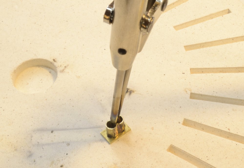
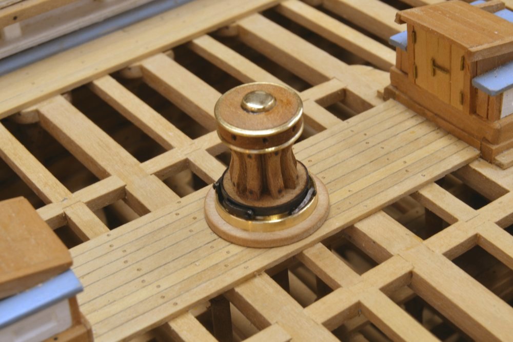
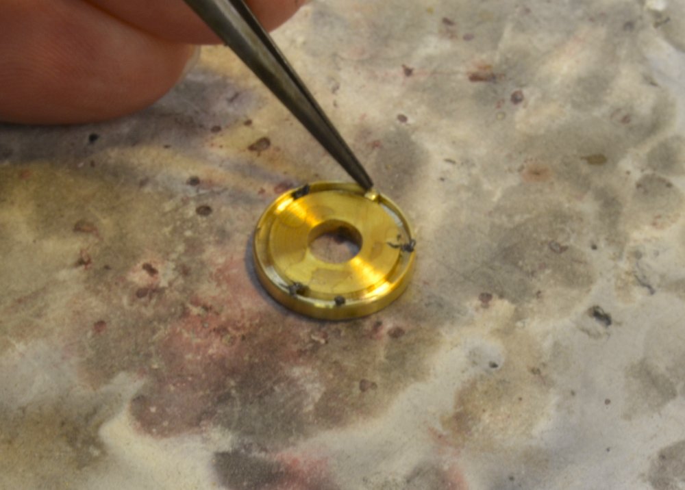
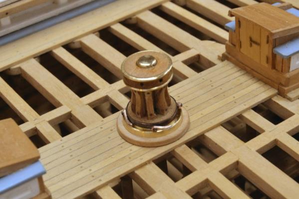
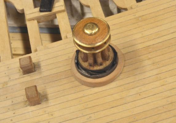
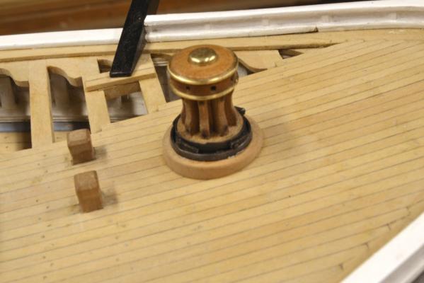
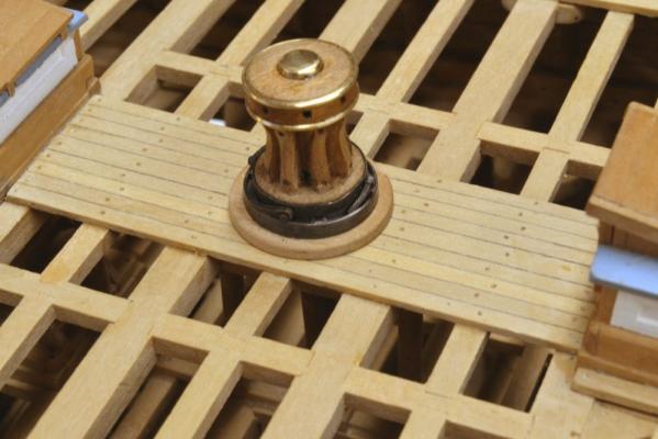
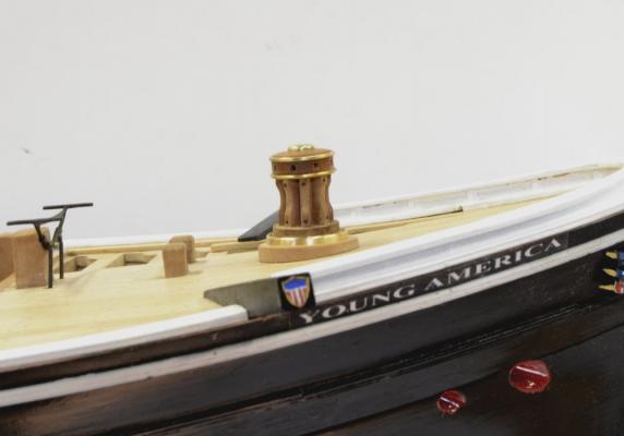
Young America - extreme clipper 1853 Part 136 – Capstans 4 This post will wrap up the work on the two capstans. In the first picture 4 copper pawls have been added to the main deck capstan. These are loosely bolted to the lower disk through the iron (i.e blackened copper) band. At full scale these would drop easily into the baseplate groove. At this scale they drop sometimes. These were made to be reversible. They could be flipped over to allow the capstan to work in the opposite rotation. In the next picture the pawls have been blackened with liver of sulfur d and flipped. In the next picture one of the baseplates has been removed to add four pawl stops. These are small (3” x 3” brass cubes. the black dabs in the picture are solder/flux paste. When the four cubes are fitted in place in contact with the paste the entire assembly was torched to flux the solder. The next picture shows the forecastle capstan set on its blacked, finished baseplate. Both the base plate and the wood base were still loose at this point. The base plates were then epoxied into the wood bases. In the next picture small wood stops are being glued to the spindle to hold this entire assembly together while allowing the capstan to rotate on the baseplate/wood base assembly. When the wood bases are glued to the deck, the brass pins at the base of the spindles fit into holes previously driled in the steps on the deck below. In the next two pictures the wood bases have been glued to the deck, completing the installation. The two capstans rotate freely and are pretty reliably stopped when the rotation is reversed. The next task is one I have been anticipating (and perhaps dreading) for some time – the bilge pumps. Ed


- 3,618 replies
-
- 38
-
-
- young america
- clipper
- (and 1 more)
-
Thank you, Glenn. Most appreciated. I'm afraid my work pales beside the magnificent parts you are turning out. The flaws in my pieces are all too visible. I am fascinated by what you are doing. Ed
- 3,618 replies
-
- 3
-
-
- young america
- clipper
- (and 1 more)
-
Thank you all. Its a pleasure doing this when I think someone may benefit. Of course from return comments and suggestions that beneficiary is often me as well. Greg, for me a task that rivals rigging is by far making a lot of cannons - and rigging them of course. I did that once. Cheers everyone. I've got a lot of snow to blow today. Ed
- 191 replies
-
- 5
-
-
- young america
- clipper
- (and 1 more)
-
....like for example Amazon: http://www.amazon.com/gp/product/B004V7P1VQ?keywords=van%20dyck%20crystals&qid=1453569420&ref_=sr_1_2&s=hi&sr=1-2 Ed
-
Further to the water based walnut stain aka Van Dyck Crystals. Here's a link: http://www.highlandwoodworking.com/vandyckcrystals.aspx I am sure there are many other sources. Ed
-
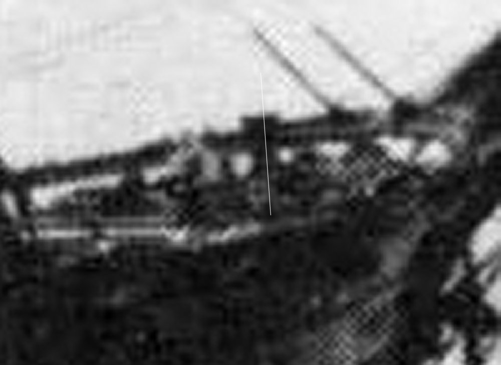
Well Druxey, when you leave the well-documented, comfortable world of the Royal Navy, things become a lot less certain. So thanks for the moral support. This would have been an easy decision based on the predominance to deck-perpendicular capstan spindles on RN drafts - to say nothing of common sense, but no less an expert the Howard Chapelle shows them vertical on virtually all of his drawings of large ships of the period. Campbell actually shows tapered bases in his capstan sketches, etc. etc. As a matter of interest, here's the photographic evidence. The white line is mine. Then there is Webb's half hull model in the Smithsonian. Not much to go on. To say nothing of other inconsistencies. Ed


- 3,618 replies
-
- 12
-
-
- young america
- clipper
- (and 1 more)
-
Remco, I agree it looks more pronounced in the latest picture, but not unlike a semi-transparent presentation that shows some wood grain. If the wale was uniformly dark before applying the oil, it is likely that the oil leached some stain out of the wood. This would not be surprising considering that the Fiebings is a solvent borne stain. This effect would be worsened if a Tung oil "finish" was used as opposed to pure Tung oil. Both could leach solvent-borne stains but the word "finish" usually implies the addition of solvent driers to the mix. This would increase the tendency to dissolve the stain. I have experienced this problem on furniture finishing with penetrating oils on stained wood and finally adopted a surface finish (wipe-on poly) preceded buy a thin shellac seal coat to fix the stain on this type of work. If you want pure black on the wale, why add oil? You could protect the underlying stain and add the desired level of gloss with a surface finish like rubbed shellac or varnish. Wipe on poly could be used but that wiping might also pull out the color. I used acrylic ink on Naiad with some transparency. Nothing short of acetone or the like will leach that out - or effect the level of transparency. Shellac based India ink will also resist oil (but not alcohol) topcoats. Druxey's sanding solution may remove enough wood to get below the oil and allow the wale to be re-stained, but I would be afraid that non-uniform oil penetration depth may leave you with light spots when re-staining. The presence of the oil topcoat will be difficult to cover with a non-oil based finish, so unless you want to use an oil-based paint over the existing finish, you may be in for some sanding. After that I would consider staining with something like acrylic or India Ink followed by oil, shellac, wipe-on poly or a varnish, but whether to repair or how to do it is something you will need to decide and be comfortable with. I would make just one recommendation if you decide on a repair. Duplicate the problem on some scrap wood, following the identical sanding and finishing process used on the model. Then test your proposed fix on that before doing anything to the model. Hope this helps. Finishing is always risky. Ed
- 1,215 replies
-
- 11
-
-
- sloop
- kingfisher
- (and 1 more)
-
Looking good, Gary. Ed
-
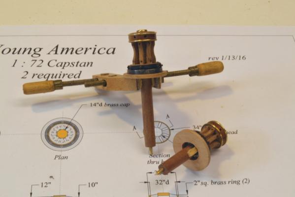
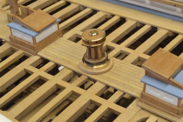
Young America - extreme clipper 1853 Part 135 – Capstans 3 With the capstan upper works mounted on their spindles, the next task was to make the baseplates and underlying timber supports. Lacking cross-sectional details for these, I decided to mount them on an iron baseplate that would incorporate the anti-reversing pawl ring. The appearance would be as shown in pictures of this type of capstan. The iron baseplates with a groove around the outer edge were made first. Stops for the pawls would later be soldered into the groove. The first picture shows a baseplate being turned in brass. A hole was first center marked and bored to fit the spindle diameter. After turning to the final outside diameter of 44”, a 3” x 3” grove was then face turned as shown in the above picture. The inside of this groove will be flush with the o.d. of the capstan bottom disk with its ½” thick iron rim installed. In the picture this baseplate is being parted off. The baseplates will be used to gauge the fit into the wood bases that were made next. In the next picture, a pear block has been turned to the outer 54” diameter of the round wood base and the seat for the iron base plate is being face turned. The grain digestion of these wood bases is fore and aft. The next picture shows one of the baseplates being test fitted. In the next picture the wood base is being parted off. The main deck capstan has been temporarily set on these base parts in the next picture. The iron band around the lower ring has been fitted and cemented to the disk with CA. It was made from a leftover bit of hull strapping, measured to the circumference and silver soldered at the ends. The main deck at the capstan location is virtually horizontal, so the issue of capstan rake did not have to be addressed. This is not the case for the forward capstan that is mounted on the forecastle decking. There is a lot of sheer on this deck, so the rake question had to be addressed. I find this to be an interesting issue. If the capstan is mounted vertically on a deck with considerable sheer the men will be forced to bend and raise their backs as the work their way around. Making the capstan perpendicular to the deck seems a logical solution. Being vertical offers no practical advantage that I can see. However, capstans are shown vertical on many drawings, including Bill Crothers’ drawings that I have as a reference. On the other hand, one of the Young America photos seems to show the forecastle capstan canted somewhat aft. To try and resolve this, I looked through every clipper ship drawing and photo in the dozens of references that I have on these ships (Crothers, Chapelle, MacGregor, Campbell and others). This left me exhausted and not completely satisfied. I concluded that capstans were generally shown vertical on most drawings, but might be canted aft somewhat on decks with substantial sheer. I decided to make the forecastle capstan essentially, but perhaps not precisely, vertical. To do this, the wood base must be thicker at the aft end. To accomplish this, the wood block was canted in the four jaw chuck after face turning the baseplate recess – as shown in the next picture. In the picture the base is being parted off in the angled position. The next picture shows the capstan temporarily fitted on its base. It has a slight rake aft that I thought was appropriate given the appearance of the actual capstan in the photo of the ship. In the next part, the pawl stops and ratchet arms will be added and the capstans permanently mounted. Ed
- 3,618 replies
-
- 41
-
-
- young america
- clipper
- (and 1 more)