HOLIDAY DONATION DRIVE - SUPPORT MSW - DO YOUR PART TO KEEP THIS GREAT FORUM GOING! (Only 68 donations so far out of 49,000 members - Can we at least get 100? C'mon guys!)
×


EdT
-
Posts
2,214 -
Joined
-
Last visited
Content Type
Profiles
Forums
Gallery
Events
Everything posted by EdT
-
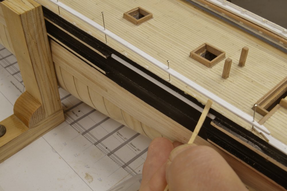
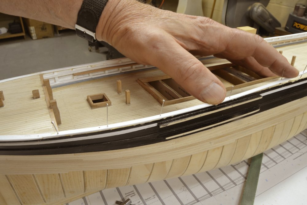
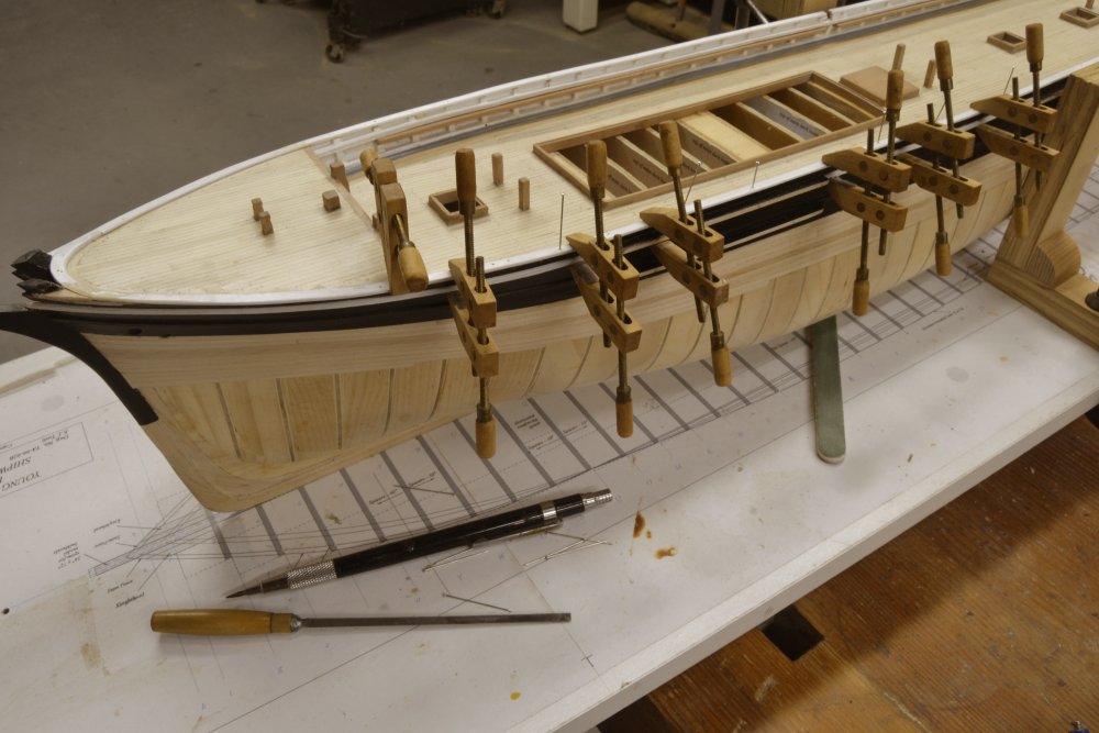
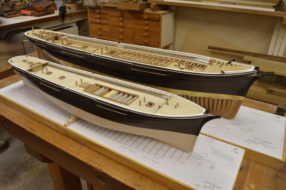
Young America 1853 – POB 1:96 Part 42– Fancy Rail Completion This will be the last post on the POB version of the model, since it’s purpose as a demo model for the book had been fulfilled at this stage. This stage of completion for both models constitutes the scope of volume I of the book and can be seen in the last picture in this post. This point was reached on the framed version at the end of May 2015 and for the POB version in early October 2015 – just before the NRG Conference. The only step remaining to be covered on the POB version is the completion of the fancy rails that cap the bulwarks along the main deck - quite a simple process after the curved shapes at the ends. In the first picture a section of rail on the port side has been made, painted and pinned in place. The pins are placed in the toptimbers. The holes will later be filled with copper wire bolts to reinforce the connection and fill the holes. The width of this rail steps down at each of the breast beams. The reason for wider widths at the poop and forecastle were explained in an earlier post. In the next picture the rail has been raised on the pins so glue can be applied to the top of the bulwark and toptimbers. As I have noted at other times, this method avoids having to find pinholes under a layer of glue. In the next picture the rail has been pushed down and clamped. At this stage all the excess glue was washed off with water. The next three pictures repeat the process on a forward section of the starboard rail. Once all the pins had been removed, wire bolts were epoxied in and the top of the rail was filed/sanded smooth and repainted. The sides of the rails were left untouched to avoid having to paint the white/black joint line. The last picture shows the POB model at completion next to big sister. All the remaining work that will be done on the larger framed version will be by methods that could be used on both. That remaining work, including masting and rigging, are planned to be included in Volume II. Those that attended the NRG conference at Mystic will probably have seen the models pictured above. For the conference they were mounted on temporary bases with the base drawings attached. The POB version remains as shown, residing in my basement. The framed version has progressed substantially, as followers of the other blog will have noted. I hope the increased level of method description in these postings will prove helpful to purchasers of the book who wish to build the POB version. As I mentioned earlier, I have made these posts and given more process detail to supplement the information provided in the book on this version. I like the size of this model and it is very tempting for me to consider finishing and rigging it, but I suspect after doing that work on big sister I may be in for a break and perhaps something different. We’ll see. Ed


- 191 replies
-
- 32
-

-
- young america
- clipper
- (and 1 more)
-
Gaetan, I looked up the product you recommend. It is a solvent based carbon black, pigmented stain. It does not appear to have any binder, so it works as a non-fading black dye. Looks like a good choice to me. Piet, I would not be very optimistic about removing oil (tung, linseed, whatever) that has penetrated the wood. Once this has penetrated and dried - in fact polymerized - the oil becomes impervious to most solvents and almost impossible to get out, especially if the finish is made from oils that have been boiled (cross-linked). There is, of course, sandpaper, but that seems extreme and risky. Ed
- 1,215 replies
-
- 3
-
-
- sloop
- kingfisher
- (and 1 more)
-
Check my Young America posts or Remco's Kingfisher post on turned wheel spindles for a method. Ed
-
I like the water soluble walnut dye idea. Vegetable dyes should not fade and I assume there is no binder involved that will effect the use of glue on splices, etc. I have often wanted to try soaking black walnut husks in alcohol to produce a non-fading furniture stain, but have not done it. Maybe now is a good time. I wouldn't dream of using Floquil for this even if it were still sold. I have used acrylic ink diluted, but wonder how this will affect gluing (non-CA gluing that is). Thanks for the walnut tip. Ed
-
Moxis, Producing rope to match all the correct required sizes is not a simple matter - at least not for me. Some up front work is required. The process I have used in the past and am now into for Young America may be helpful to you: The first order of business is to produce a rigging list that among other things specifies the size and type of every line. Sizes can come from Steel, Lees, Underhill, drawings or other depending on the era and type of ship. Although this may reveal the need for chain or wire, I will stick to rope. From this, develop a list of all the sizes needed, whether the rope is right or left hand. You may also want to distinguish 3 vs. 4 strand, but I find this hard to differentiate on models without close examination. I assume you will be making your own rope and are able to turn out consistent sizes for a given recipe. Rope sizes are given in circumference. Divide this by 3.14 to get rope diameter. Convert the scale diameters to actual measure and add this data to your list. Then determine the material you will use. I prefer linen for hardness and stretch resistance, but good linen is almost impossible to get since Barbour closed their operations in Lisburn, Ireland. Some of their business was picked up by Coats, but the quality does not seem as good and the most usable size (100) is no longer (?) made. There may be good lacemaking linen available and I would love to hear about sources, but I have found quality wanting. Only the very best quality linen is free of fuzz and slubs (bumps of fiber). This leaves cotton, which commonly used by many modelers. I have not used cotton, but expect to use it on some smaller YA running rigging. Use long staple (Egyption) cotton to reduce stretching. I used mercerized cotton polyester on my 1:96 Victory model for small lines (<4"). It worked well and has not sagged in the last 8 years, but can be somewhat fuzzy. When you have decided on material get some of the smallest size available. I use 4 different sizes of linen, some very fine crochetting cotton and some quilting cotton, which has a smooth finish. I use white thread then stain it later. Then start making rope. I start by making the small sizes. One thread times 2, 3 and 4 strands. This yields three sizes of rope. Two strand rope is inauthentic but spun tightly produces a better looking model rope than most plain thread. Measure these with a micrometer and match each size made against the list. Repeat this with heavier thread, using multiple threads per strand, or using some of the small made rope sizes to produce larger (cable laid, opposite hand) rope until you have found a ropemaking formula for each required size. You may not get perfect size matches and some made rope may need to be used for more than one required size. The smallest sizes may required the used of plain thread. This testing and tabulation may seem like a lot of work, but once done you will have a recipe for each size rope, will know how much of each thread to purchase and will be able to quickly crank out what you need. I spent a week before Christmas doing this analysis for YA where rope sizes go from 3/4" to 11" and use almost every size in between - including fractional inch sizes. Good luck. Ed
-
Remco, your work is beautiful and I am sorry you are having finish problems. Frankly, I cannot detect anything in the photos, but I know we are often our own worst critics. One could not do extraordinary work like yours without that. I will preface the following by saying I realize I am swimming upstream in the face of many modelers who use dyes on their models. So, forgive me. One problem is that all dyes fade with time. This is accelerated by UV light that breaks down complex aniline dye molecules. I suppose it is possible that compounds in wood may also react chemically with the dye. I don't know about this, but it may account for some of the effects noted. I have not used Fiebings but I assume it is aniline based. Virtually all dyes today are. However, I have used other good quality aniline dyes on furniture work because they are much clearer that pigmented stains in transparent finishes. All these pieces have faded over time. I have searched in vain for non-fading dyes. Pigments, like carbon black, do not fade since elemental carbon is not a molecule that can be broken down. This is true for most pigment colors. Any good pigmented ink, for example artist's acrylic inks or India ink will never fade. Finely dispersed pigments in these products will penetrate the wood fibers and stain like dye. Also, they will be locked in the ink binder when dry - acrylic polymer or in the case of India Ink, I believe, shellac. This introduces another problem with dyes. They remain soluble after drying, meaning that if water borne they will run when dampened unless a topcoat is applied. Solvent borne dyes will run if wet with solvent - unless the dyes contain a binder, which I believe is not typical. Ed Addendum: Since I have not used Fiebings, I checked into it. From the attached MSDS sheet it is clear that although sold as a dye, it is in fact pigmented with metal oxides, so although apparently not carbon black, it should not be subject to the fading problem I describe above. Fiebing Leather Dyes-standard & 200 series except white & ….pdf
- 1,215 replies
-
- 11
-
-
- sloop
- kingfisher
- (and 1 more)
-
Thank you, Ian. I could have said more about the whelp mortises. I initially cut these with a 1/32" square end mill - 8 of them, about .025" deep around a cherry spindle roughly 3/16" in diameter. The setup had to be very precise because the slots are very close together, too close in fact for a strong structure or a really clean result. I could have persisted with this or gone to a harder, stronger wood like Box, but since none of this detail is visible - or even necessarily authentic, I decided to simplify. Another reason to simplify is that I would not like to make a milling machine a prerequisite for builders of the model from the book, so I usually try to find other methods, or at least suggest alternatives. For example, the ladder slots and the capstan bar mortises could be filed out in a pinch. I believe the work described in Volume I could be done without a lathe or mill. A lathe is probably needed for some of the content that will be included a future Volume II - but I hope to avoid the necessity of an expensive tool like the mill. We'll see. Ed
- 3,618 replies
-
- 14
-
-
- young america
- clipper
- (and 1 more)
-
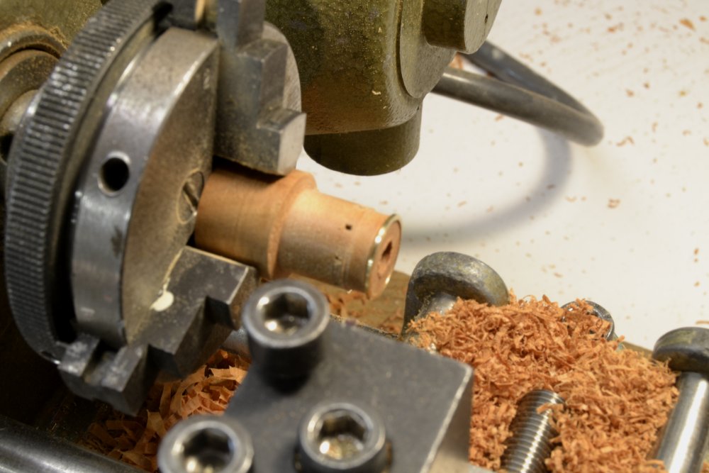
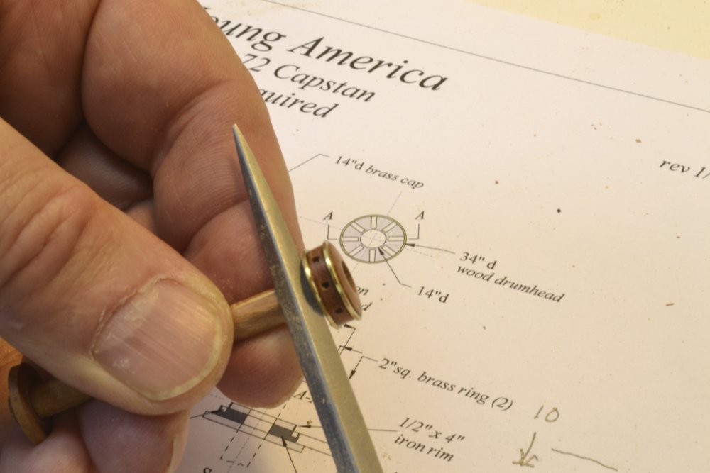
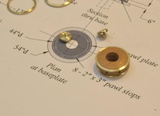
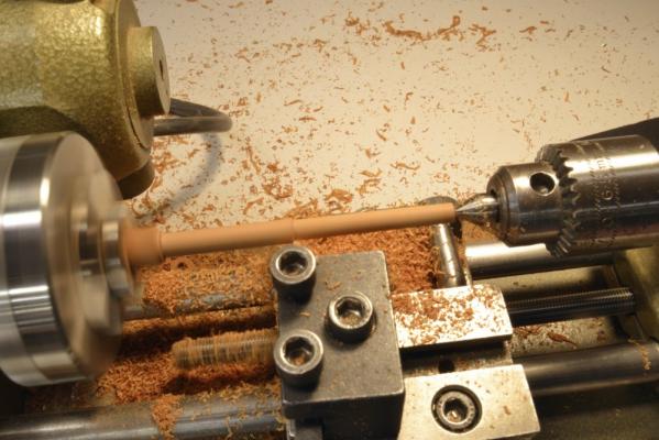
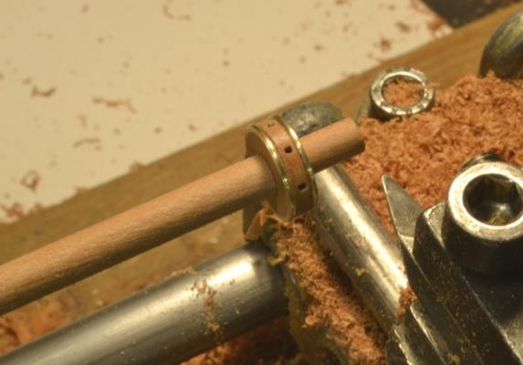
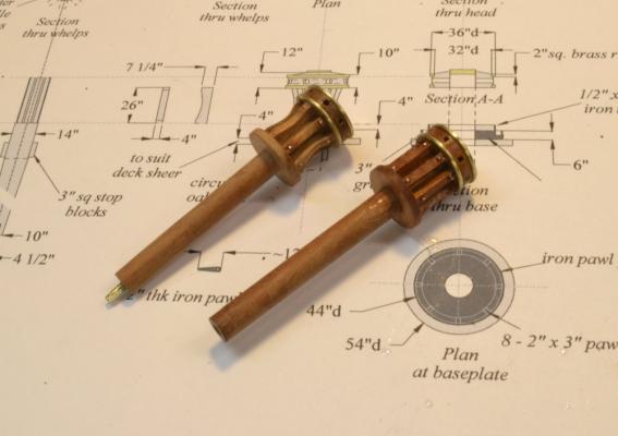
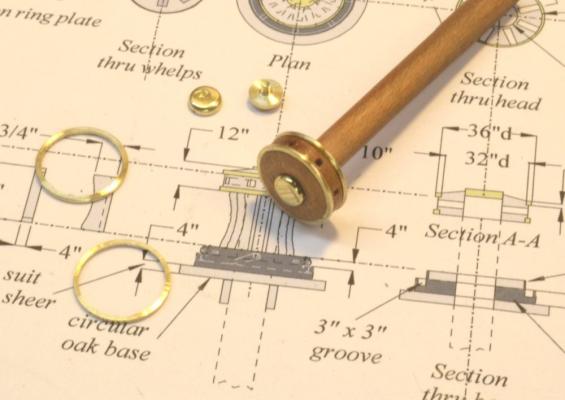
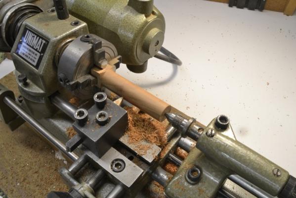
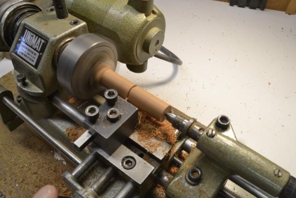
Young America - extreme clipper 1853 Part 134 – Capstans 2 In the last post the top, mortised section of the drumhead was inverted and glued on the base turning to produce the square mortises shown in the first picture. In this picture the piece has been turned to the final 34” diameter of the head. The top part was then turned carefully to fit the 32” i.d. of the top brass ring. When a snug fit was produced at the end of the turning, that diameter was taken down to the seat of the ring – about 2” above the mortises. The excess material was then parted off the top of the head as shown below. Enough was left to produce the rounded up top of the head which was then turned. The cutter was then set at the depth of the ring seat, backed off a measured amount, moved to the left to cut the lower ring seat, then dialed back down to that diameter. The head was then parted off and the rings pressed on as shown below. In this picture the rings have been cemented with thin CA glue and the top polished. The next step was to make the 14” diameter spindles. As shown above, a cherry turning square was fixed in a four-jaw self-centering chuck and held for turning with a dead center at the tailstock end. In the next picture one of the two drumheads is being test fitted over its spindle. The head was then glued to the spindle and the brass cap cemented into place. In the next picture the flats for the 8 whelps are being filed on the spindle below the drumhead. I had initially intended to mortise slots for these but the small size and the relative softness of the cherry left an undesirable result after milling, so I decided to simply file flats using the spaces between the head mortises as a guide. The whelps were then made and glued on. After the glue dried the whelps were secured with two epoxied bolts each. Lower disks were also made and fitted to each. The two capstan assemblies at this point are shown below. The whelps on the left capstan in the picture have been rounded concave and the wire bolts have been filed off flush. The spindle on this capstan has also been cut to final length and a pin inserted in the bottom that will secure it at the step on the deck below. This will be the main deck capstan. The one on the right will be mounted on the forecastle. In the next part the iron baseplates with their pawl stops and the underlying wood bases will be made. Some details of the baseplate can be seen on the drawing in the above picture. Ed
- 3,618 replies
-
- 36
-
-
- young america
- clipper
- (and 1 more)
-
Thanks, everyone. Good to hear from you, Robin. I hope you will soon be feeling better. Frank, a good question. I believe the best way to have clamped these two pieces would have bee to chuck a length of the spindle and use it to precisely center the two pieces then push up the chuck to clamp them - hopefully not gluing in the spindle piece. Unfortunately I had not yet turned these, but an improvement would certainly be to turn them first and then use them when boring the hole and in the chuck to clamp the pieces. I aligned them by feel and this seemed to work OK, but using a positive alignment in the hole would be better. A good fit here is necessary so the head fits squarely on the spindle. In retrospect I might also have bored the spindle hole in the lathe either before parting off the top, or after gluing it back on. The actual spindle could then be used to size the hole. Good question. Grant, I am no expert and sometimes need to try different things - and scrap some work - to find a solution. There are some good tips in the Unimat and Sherline instruction manuals and there is also a useful manual sold that uses the Sherline tools in its examples. Ed
- 3,618 replies
-
- 4
-
-
- young america
- clipper
- (and 1 more)
-
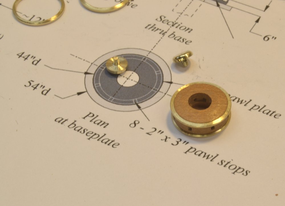
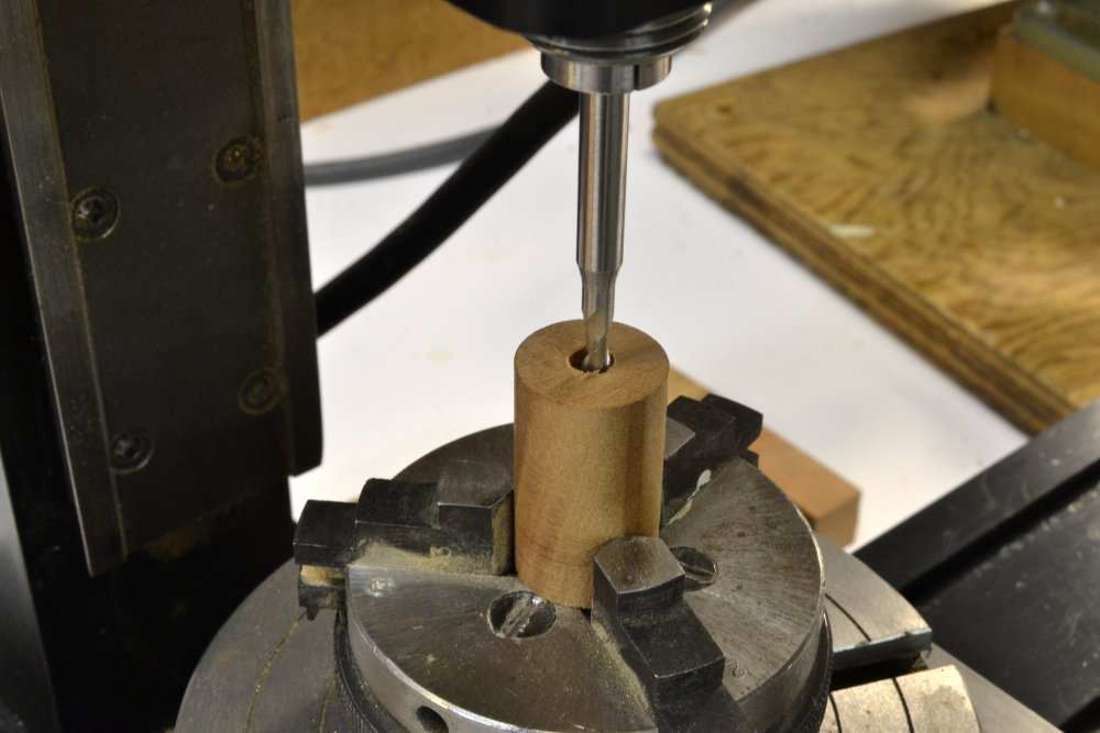
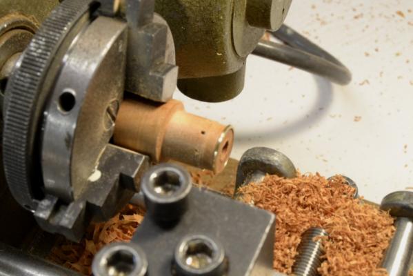
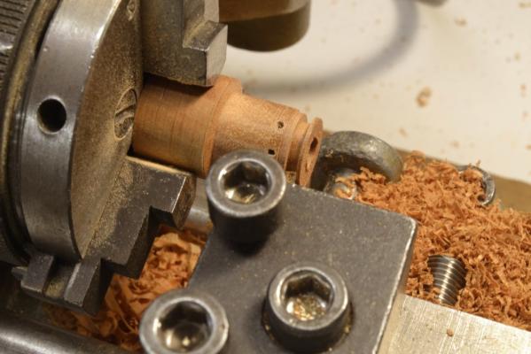
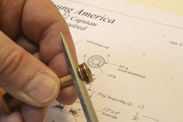
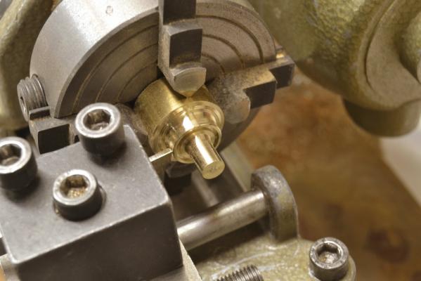
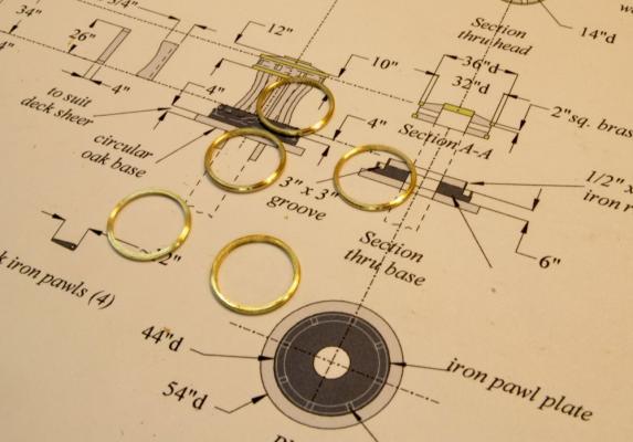
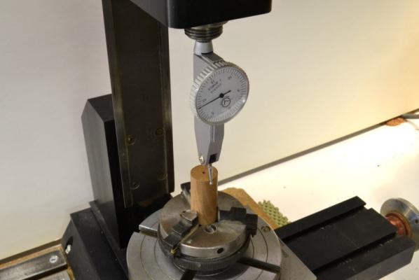
Young America - extreme clipper 1853 Part 133 – Capstans 1 Young America had two capstans, one aft of midship on the main deck and one on the forecastle. These were lighter and smaller than the massive two-deck capstans we are used to seeing on 18th century warships. Since the windlass handled the weighing of the anchors, the two capstans were used for lesser loads, for example mooring, raising spars or heavy cargo handling. These were often ornate, featuring polished brass rings and made of decorative woods like mahogany. I based the design of the model anchors on American styles described by Campbell in his China Tea Clippers and by Crothers on his drawings of the ship. I will try to provide an (admittedly incomplete) overview of how these were made. The first step was to make the drumheads. A picture of one of the finished drumheads mounted on its spindle is shown in the first picture. The drumhead, and indeed all the wood parts for these are cherry for the darker color. The rings and cap are polished brass. The holes for the capstan bars are 3” square. The parts are laid on a copy of the drawing made for these – one of the earlier of many revisions. The realities of working many of the planned details at this scale – like mortises for the whelps, etc. caused me to simplify some of the construction while retaining the essential appearance. The first drumhead parts to be made were the brass rings and caps, so these could be fit to the wood head as it was machined. The next picture shows one of the rings about to be parted off in the Unimat® lathe. The central shaft left in this picture would be used to make the caps. The next picture shows the rings made for the two capstans plus a spare. In the next picture a cylinder is being turned that will be used to make the two cherry heads. The excess length was provided to allow for chucking pieces for each head. The grain direction of the piece shown is perpendicular to the lathe centerline. The turning is centered at the tailstock. Precise centering of these for turning the ring seats and boring the hole for the spindle was critical so that all would be concentric. The cylinder at this stage was left larger than the 34” diameter drumhead. In the next picture the first piece is being parted off. In the next picture one of the cylinders has been placed in a three-jaw centering chuck on the rotating table on the milling machine and is being centered on the spindle. The dial indicator mounted in the spindle was used to center the cylinder within one or two thousandths of an inch using the cross feeds on the mill. In the next picture a center hole has been bored and the 1/8” milling bits is being used to enlarge the hole to the 14” diameter of the capstan spindle. This was done by offsetting the y-feed to the enlarged size then boring the hole by rotating the table. The rotating table and the y-feed were then used to cut mortises for the capstan bars as shown below. The 1/32” end mill was lowered 3” into the end and set using the vertical calibrated mill wheel (z-axis). When the four cuts (8 slots) were finished, the piece with the chuck was returned to the lathe as shown in the next picture. In the picture an oversized top piece is being parted off. After cleaning out the slots with a small square edged file, the cap was inverted and glued to the cylinder in the lathe as shown below. The glue joint is clamped using the flat end of the drill chuck screwed tight with the tail stock wheel. When dry, this piece was ready for turning the final diameter, fitting the rings, shaping the top, and parting off to yield the piece shown in the first picture. To be continued… Ed

- 3,618 replies
-
- 28
-
-
- young america
- clipper
- (and 1 more)
-
1:96 is a great scale for one of these models - large, but not excessively large. The model can be realistically rigged at this scale. I think 1:72 is a better scale if the model is to be fully framed, but the 1:72 model is quite large. For these reasons I included both scales in the book, with the 1:96 model based on a POB design that I had been wanting to try out. The design uses an erection process for the bulkheads that is very similar to that used in upright full framed construction that I think is a good learning step for builders who may not feel ready to jump right into full framing. Ed
- 3,618 replies
-
- 4
-
-
- young america
- clipper
- (and 1 more)
-
Thank you Erik, I am delighted if you have become a convert. Clipper ships are good, especially the many lesser known American greats. I too like naval subjects, but he world has plenty of model warships - including two from me. I plan to rig the 1:72 version and that will be the subject of Volume II of the book. However the rigging information in the book will cover both scales. The 1:96 POB model was done as a demo model for Volume I of the book and is finished as far as planned. The build log on that will be winding up with the next post or so.The design/drafting work for the rigging is well along, but that work cannot really start until I complete the deck "furniture." Ed
- 3,618 replies
-
- 6
-
-
- young america
- clipper
- (and 1 more)
-
Yes Druxey - or like me making my way along Victory's gun deck. Grazie, Alberto. Ed
- 3,618 replies
-
- 5
-
-
- young america
- clipper
- (and 1 more)
-
Thank you all for the comments and likes. They help a lot in the post holiday doldrums as i try to get energized for the work ahead. Druxey, the head height under the forecastle beams is only about 4'6". The height in the lockers is closer to 5' but with the step over coaming the door height is also about 4'6". I'm sure dragging the anchor chain over that unidirectional winch from under the forecastle was no fun. Frank, you are quite right about my desire to have a process nailed down beforehand and I try to work that way once I have a process that works well. However, each process takes at least some development and that usually involves an iteration between work and redrafting - and often some scrap. For example, for the past week or so I have been working on the two capstans. They are different from the usual 18C Admiralty types and smaller than those on the Naiad model s there has been a lot of trial and error - and a drawing revision about once a day. Hope to show these soon. Crackers, from trying to comment on so much of the great work on MSW, I know it is often hard to keep finding nice things to say. Its much easier to hit the like button, but I do appreciate the comments and the time taken to make them. Ed
- 3,618 replies
-
- 12
-
-
- young america
- clipper
- (and 1 more)
-
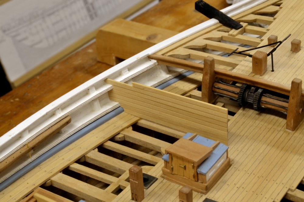
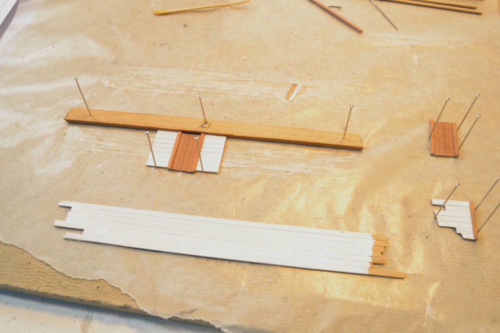
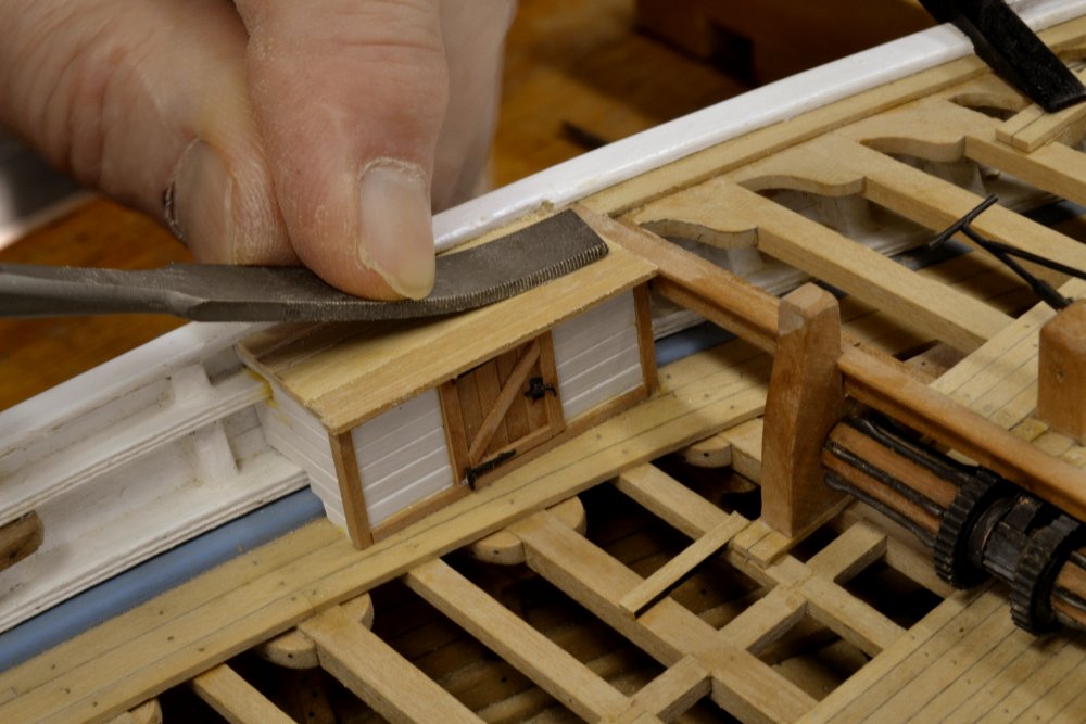
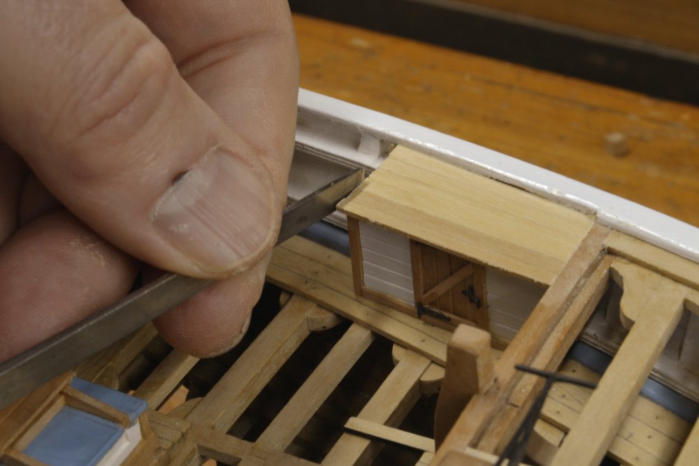
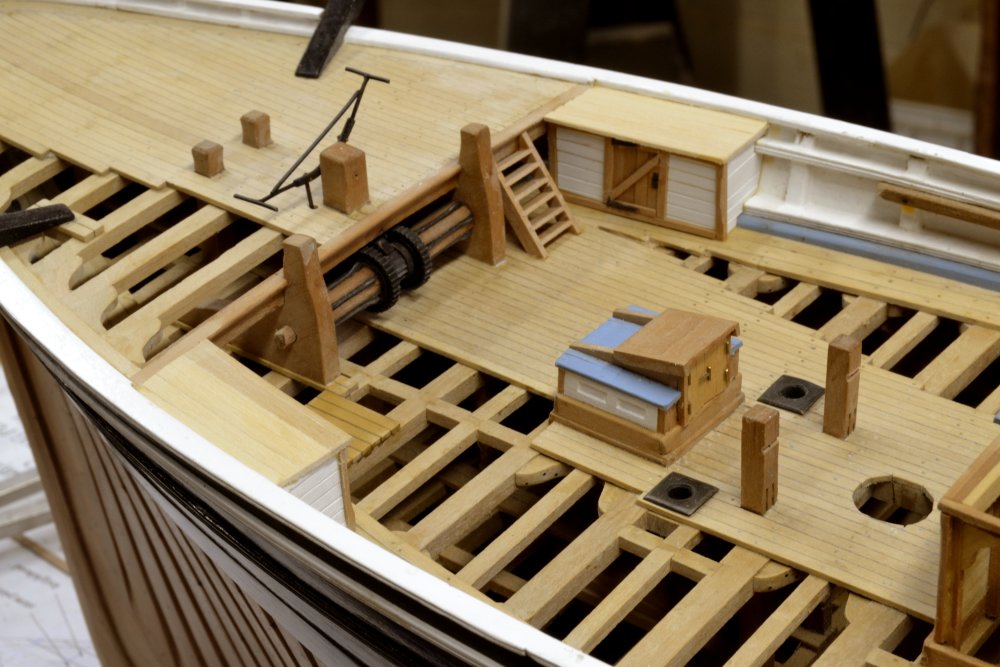
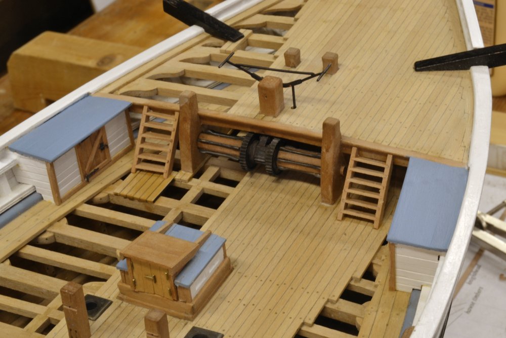
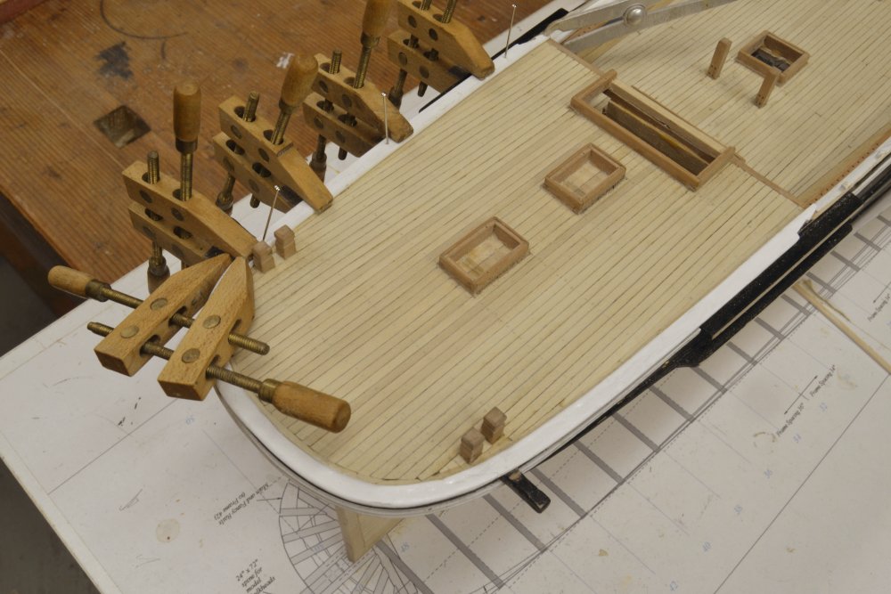
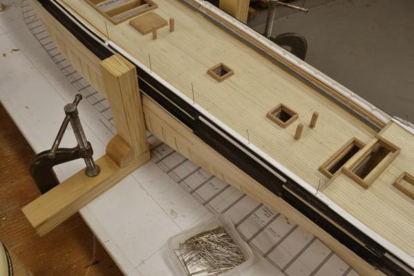
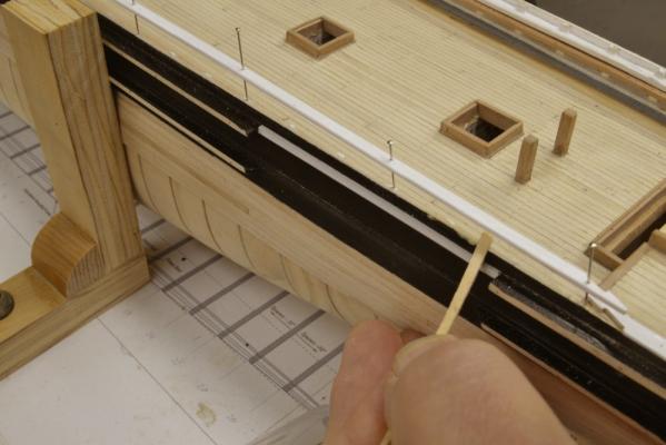
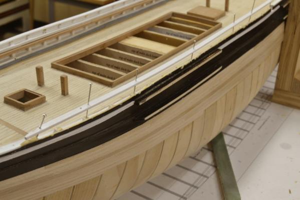
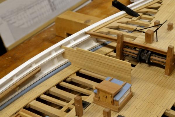
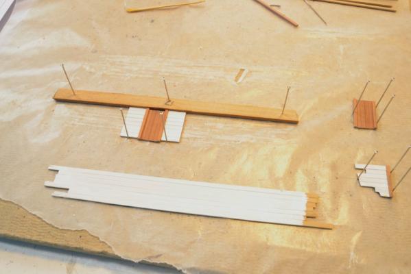
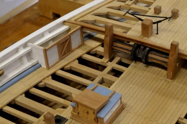
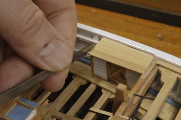
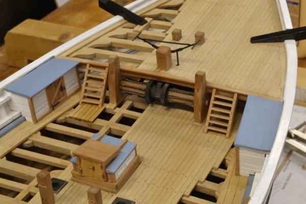
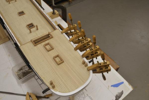
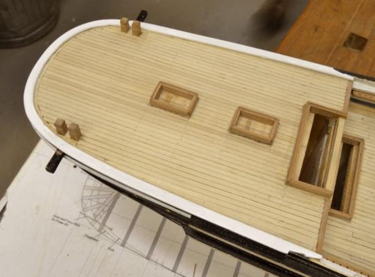
Young America - extreme clipper 1853 Part 132 – Forward Lockers There were two forward lockers that abutted the forecastle breast beam and the bulwarks at the side. The enclosure on the port side was evidently (also?) used as a toilet. These were undoubtedly used to stow gear that needed more protection than that afforded under the open forecastle. With the windlass permanently installed, these enclosures could be constructed and the ladder ways between them and the windlass also installed. In the first picture a panel of siding has been edge glued and is being fitted between the rails of the port bulwark. After fitting, the panel would be cut off square to size. These would most likely have been made using tongued-and-grooved planks maybe 2½” thick. To accentuate the plank joints, the edges were rounded before edge gluing – as was done for all the other deck structures. The next picture shows some pieces in assembly. Although the workshop is in the basement, I get very bright sunlight through the windows this time of year – hence some overexposure in some of the pics. In the next picture the end walls have been fitted and the fore-and-aft wall with the door is being test fit. In the next picture the wall has been installed, the roof has been planked and is being smoothed out. The flat faced curved riffler is being used for this. Note that door hardware was installed prior to setting the wall. In the next picture the edges of the roof planks are being pared flush with the chisel. The next picture shows both enclosures installed. The ladder way on the starboard side is also installed and the glue on some decking for the port ladder is drying. In the last picture the second ladder way has been installed and roof planking on both enclosures painted. Ed


- 3,618 replies
-
- 49
-
-
- young america
- clipper
- (and 1 more)
-
Hello Bob, For some reason your post of 22 December just popped up on the blog so I apologize for the delayed response. The mislabeling of the toptimbers on pattern sheet 2f is clearly another one of those typos - if I may use that term to describe minor glitches in labeling on the drawings. A revised pattern sheet is attached. Ed 2f.pdf
-
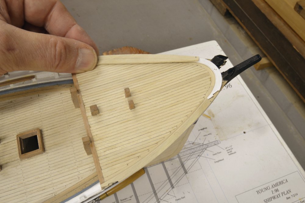
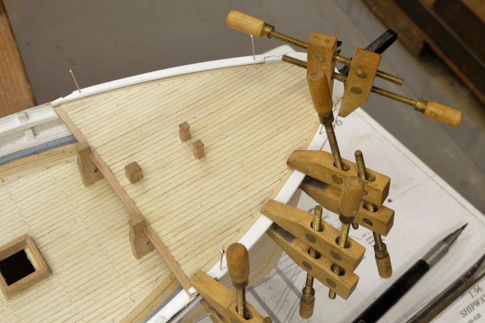
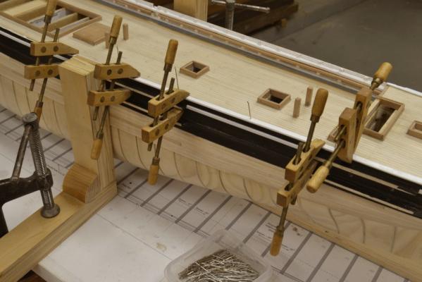
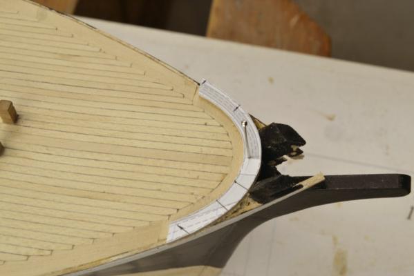
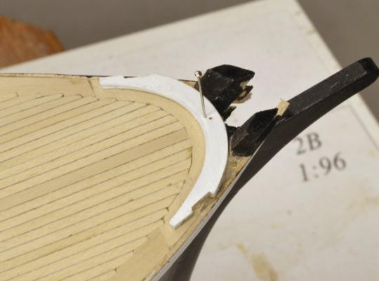
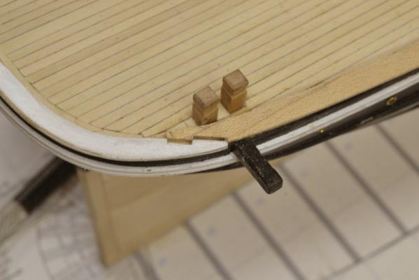
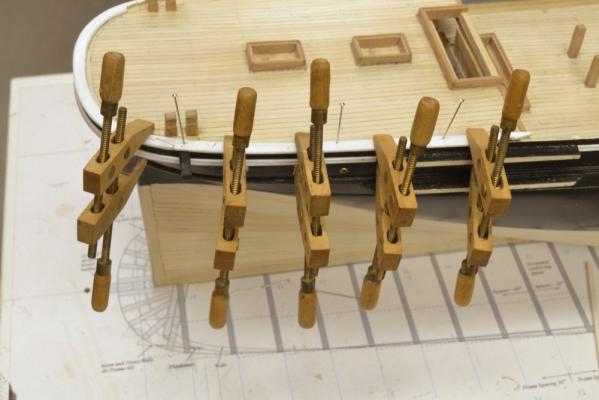
Young America 1853 – POB 1:96 Part 41 – Forecastle Fancy Rail We are almost approaching the end of the modeling I did on the 1:96 version of Young America. In the last part the fancy rail around the stern was installed. The same methods were used on the fancy rail at the bow – with a few minor differences. In the first picture, the central, forward section of the rail has been pinned in place – prior to cutting the scarph joints. A template made from one of the pdf drawings was used, since the outer shape could not be traced as was done on the stern. The joints were then formed, the inside (only) edge rounded by sanding, and the piece painted. It is shown pinned in place below. The side pieces were then fitted in the same manner as those at the stern – as shown below. The joints were then formed on these, the edges rounded, and the pieces painted before installation. The starboard piece is being glued in the next picture. Note the use of a screw clamp to close the joint to the forward section. The next step is shown in the last picture. There is a small triangular area between the knightheads and the rail on each side which must be capped. In the picture, small pieces are being fit over these areas. The outside edge of the forward piece was left unrounded for this work. Fitting these with an invisible joint required some sanding of the top faces of the installed pieces – as can be seen. These were of course painted over later – after the outside edges were made flush with the main pieces and rounded over. Unfortunately, I did not take a close-up picture of the finished work. All that now remained to do on this model was to add the fancy rails along the main deck. This would bring it to the relatively presentable state for the trip to the NRG conference in October. I will cover that last bit of work in the next – and perhaps final – part. Ed


- 191 replies
-
- 32
-
-
- young america
- clipper
- (and 1 more)
-
daves, Thank you for your comments and for the opportunity for me to expand on the decision I made for the iron strapping. While it is true that the method of iron strapping used on Young America, built in 1852-53, is uncertain, it is by no means cclear that outside strapping was widely used at the time or that internal strapping was rare. It is true that outside strapping appears to have become more prevalent after the 1850’s. Space did not permit a full discussion of the history of iron strapping, nor was in-depth construction history the primary purpose of the book. I did discuss the decision to use internal strapping in Chapter 8 of the book and quote the relevant passage: “A lattice of diagonal iron bands came into use in the early 19th century to help stiffen wooden hulls against hogging strains. Young America had such banding. The bands were normally about 4" wide by ¾" thick, spaced on a grid about four feet apart. The lattice extended over most of the hull length between the floor heads and the main deck clamps. The bands were set into scores cut into each frame to provide a flush surface for planking. They were bolted through every frame and where they overlapped. This configuration was documented for Challenge, a similar clipper launched by Webb two years earlier. However, it is not known whether the ironwork on either of these ships was installed inside or outside of the frames. Both methods were in use, with outside installation becoming more common in later years. Although it offered some technical advantage, outside strapping was much more difficult and time consuming to install. After reviewing available information and considering the urgencies of the times on construction schedules, I decided to adopt the internal installation for the model.” A more thorough discussion of the topic was included by Bill Crothers in his book The American-built Clipper Ship pp 195-196. I believe he summarized the issue quite well – and the uncertainty. As with many of the undocumented details of the model, choices have had to be made – or there would be no model. After reviewing available information on the subject this appeared to indeed be a toss-up issue. I was influenced in my decision by the following factors: - The internal or “Admiralty” system, developed for use by the Royal Navy was prevalent during the first half of the 19th Century. - Webb was the first American builder to adopt iron strapping on Challenge in 1851. - Webb used internal iron strapping on Ocean Monarch in 1856 as referenced by Crothers based on Webb’s published Plans of Wooden Vessels. - American Lloyds’ Registry of American and Foreign Shipping, 1859 includes the following passage under Rules for Inspection and Classification: “Ships exceeding four times their breadth in length, should be cross(X) iron strapped diagonally on the inside – outside strapping leakage through the seams of outside plank will corrode and destroy the iron. The bolts through the straps either from out or inside should go through and clinch.” - Speed of construction was a primary driver in the hectic extreme clipper rage of the early 1850’s – driven by the demands of the California gold rush market. Outside strapping was much more time consuming to install, especially in the days before pneumatic drills, chisels and hammers. While not a primary argument for internal installation, it was a factor considered. On balance, while not being clear cut, I believe the decision to use internal strapping on the model was reasonable and should be considered a more likely actual scenario than a one-off rarity. Ed
- 56 replies
-
- 10
-
-
Hello Bob. I hope I did not leave the impression that CNC was used to make the guide. The milling cuts were made by hand turning the calibration wheels on the mill from reference surfaces on the piece. Pretty standard milling practice. I'd be glad to explain further. I would like to hear more n your idea for mass producing knees. It sounds not unlike the solution presented in the book and in the Naiad books. Any new twist that you have would be of interest. Ed
- 3,618 replies
-
- 5
-
-
- young america
- clipper
- (and 1 more)
-
Hello, Bob, Glad to hear your model is progressing. I will try to answer your questions. First, whether the pins are wood or iron I would make them of brass because wood will not be strong enough on a rigged model at this small size. I believe they are strong enough for the service using the hard brass. The pins are on the long side. I intend to trim them to a uniform length before final finishing rather than clip them accurately when separating them in the lathe. They will be trimmed then pickled and blackened in one or two batches when all are made. It is true that the wire is inserted into the guide by sliding the tailstock forward over the chucked wire, but it is not restrained at the tail end. It is held down because the guide surfaces do not extend to the centerline of the part. File pressure is light and there has been no problem with the wire staying in place. Even the thin section at the lower end has not shown any deflection during filing. I am using a medium file (#2 Grobet) on that section and on the handle end initially then a fine round and flat to finish. They are then polished using crocus pushed down with a pencil eraser. I am not sure of the speed, probably fairly low surface speed due to the small diameter. Three cutters were used to make the guide 3/8" and 1/8" square end mills and a 1/8" ball end mill. This is a new method for me and could perhaps benefit from some improvements. One might be to leave the headstock end of the guide at full 1/4" rod diameter to more firmly hold the pin, although this has not been a problem. Doing this at the handle end would make the end difficult to round and size. However, I do not see enough potential benefit to make a new guide. Having made a few dozen of these, I am well satisfied with the final result and the efficiency. I do worry a bit about the few hundred on-off cycles on the ancient Unimat motor however. (I do have a spare.) Ed
- 3,618 replies
-
- 8
-
-
- young america
- clipper
- (and 1 more)
-
Very nice work, Micheal. I really like the method. I would second Druxey's comment on the Byrnes drawplate - an indispensable tool. I have tried several over the years, including some home made. The Brynes Model Machines tool is by far the best. I have never tried cane. I normally used bamboo for its high tensile strength that resists breakage in the die. I use mostly barbecue skewers split into strips with a knife, then select strips that have hard growth ring material. Skewers tend to be pithy. If you want a very hard, dark nail, use well weathered bamboo garden stakes. The nails from these are very strong. Ed
-
Thank you, both and thanks for the likes. Ian, the nice thing about using CAD in this case is that the piece can be drafted at full 1:1 "world" scale. All of the dimensions can be taken digitally from this drawing and converted to 1000ths in model scale for the machining. This is all much too tiny to be hand drafted to get these dimensions - without a very large board and lots of paper. When the eyes get too feeble to see this stuff the calibration wheels come in handy. Just be sure the CAD software allows you to work in 1:1 scale - then print to whatever smaller scale you need. Ed
- 3,618 replies
-
- 11
-
-
- young america
- clipper
- (and 1 more)
-
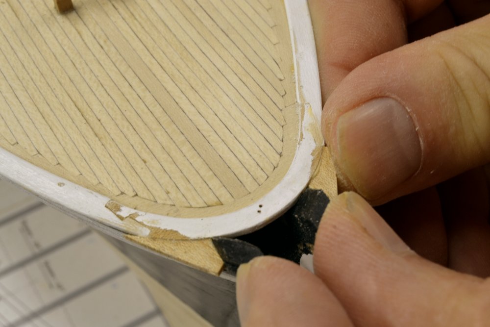
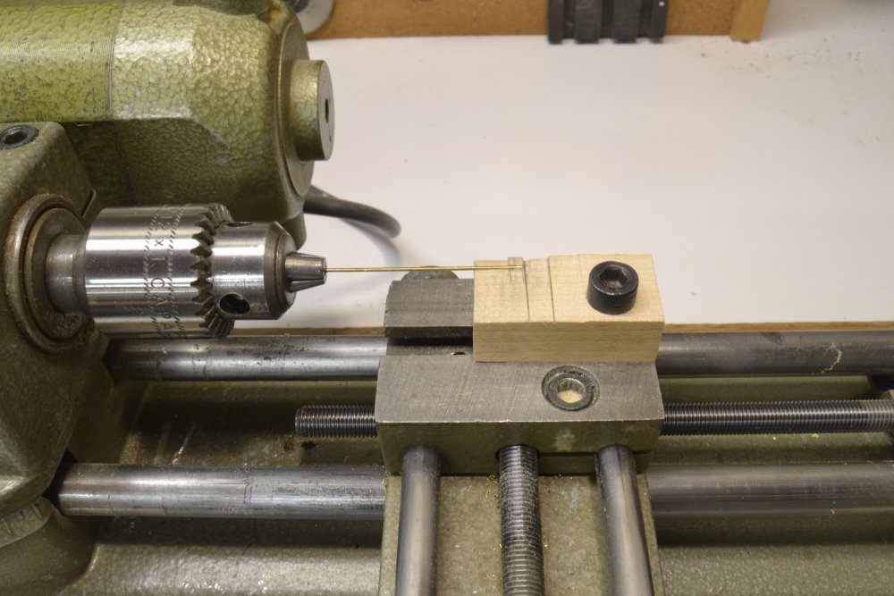
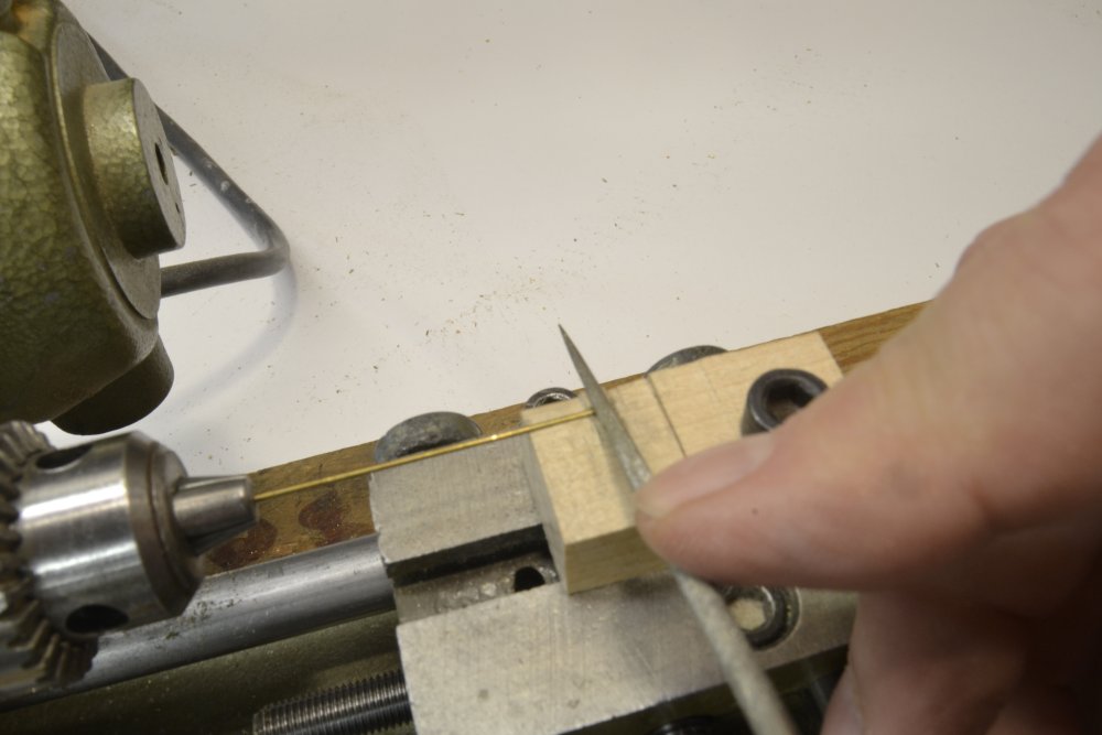
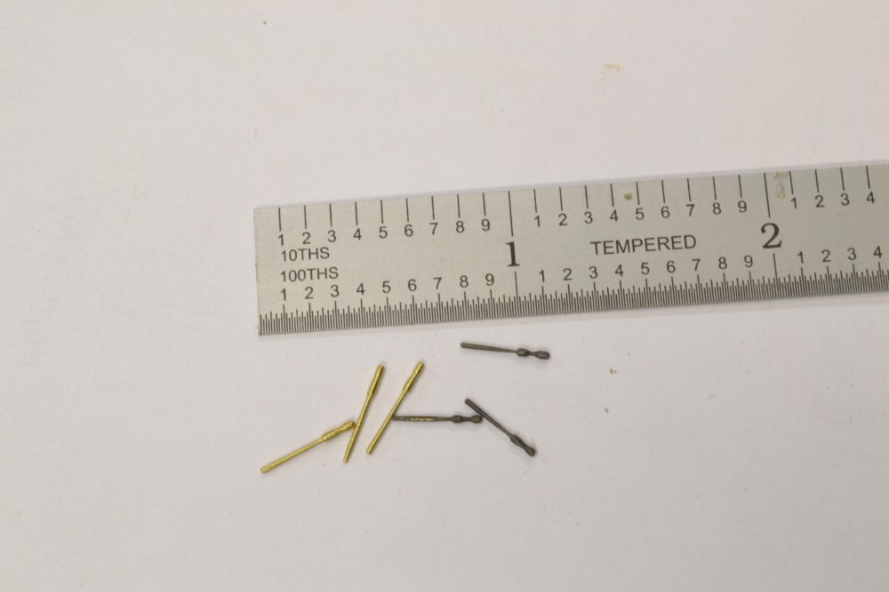
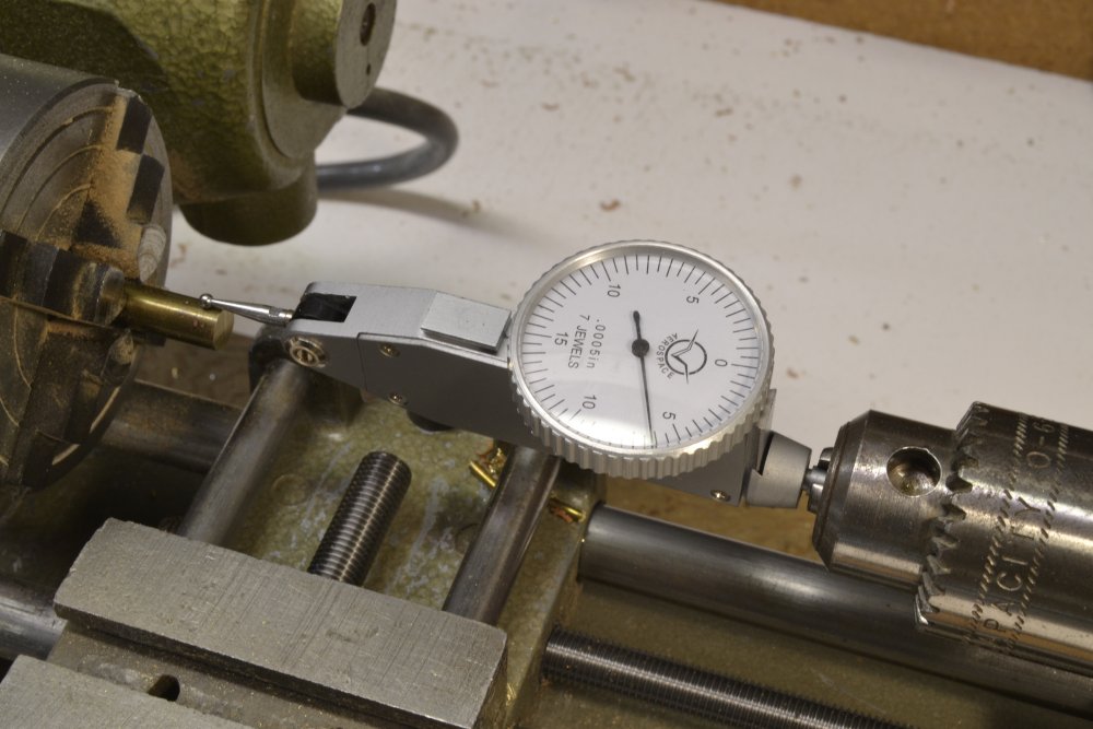
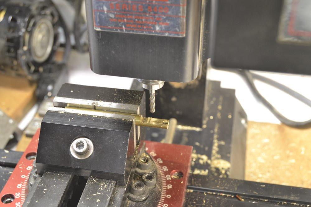
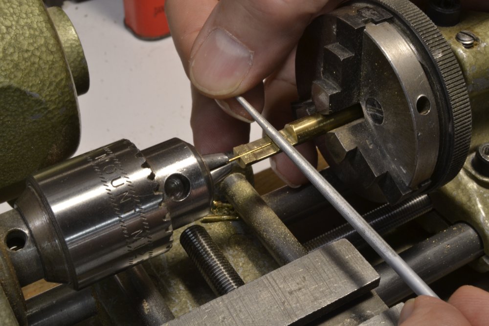
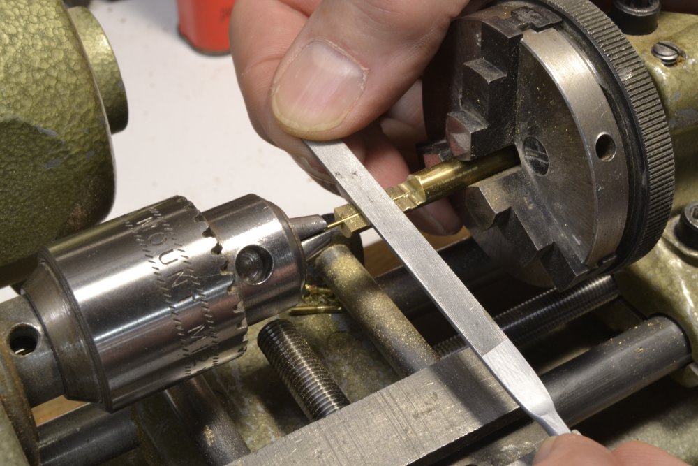
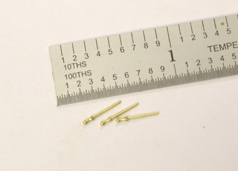
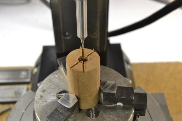
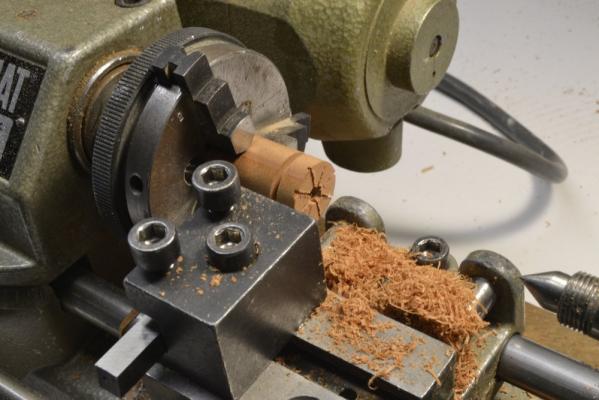
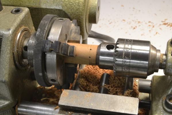
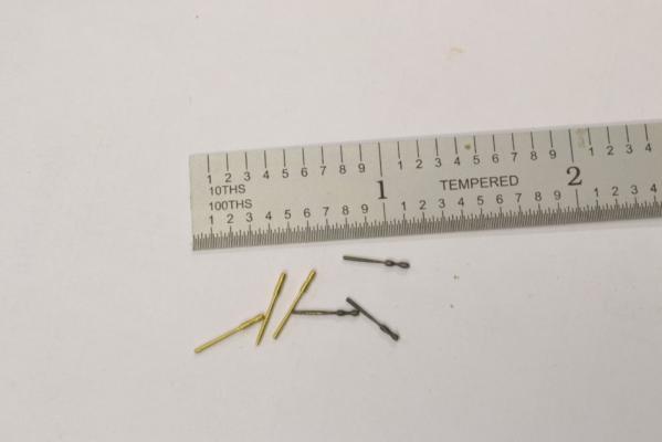
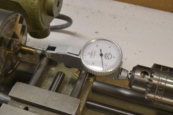
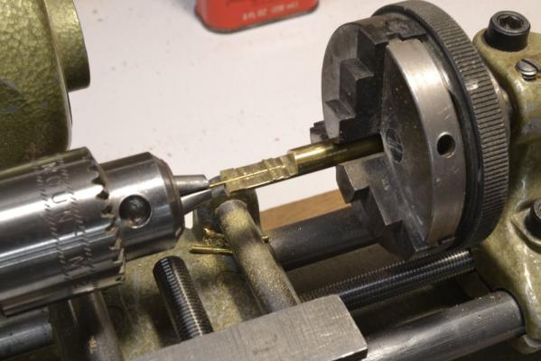
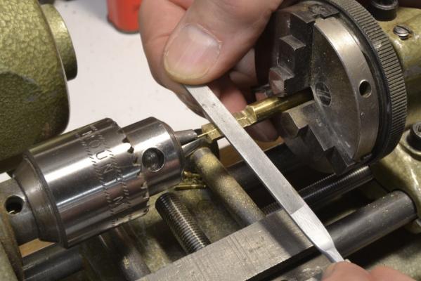
Young America - extreme clipper 1853 Part 131 – Belaying Pins Actual modeling work on Young America has been slow through the holiday period, but I have been putting a lot of effort into research on her rigging and the development of a detailed rigging list with specs for all the lines. This has been a slow process because rigging was undergoing constant change through the life of the ship – for example moving to the use of iron for many attachments and rigging lines (chain, wire) as well. Also, sources on sizes, where they exist, vary. This work will go on for some time. As this “paperwork” has progressed, it has thrown off a variety of diverting questions as to how many (small) parts will be made – for example shackles, iron strapped blocks, gin blocks, etc. I decided to tackle iron belaying pins as a side project, but one that arises soon in the construction. Model belaying pins often suffer from poor proportionality – generally being too large – especially the wooden variety. I am determined that the 250 or so of these on the YA model will not suffer from this, so I began work on making these. This started with the use of brass tubing to create a steady rest around a brass rod so these could be turned in the lathe. This did not work well on the .032” brass rod needed for these. The next step was to try filing these in the lathe using the simple hardwood guide shown in the first picture. The block was stepped and shaped to the pin outline. A v-shaped groove was cut on the lathe centerline to contain the brass rod. The next picture shows some filing in progress. The results were not too bad – as far as being proportional at least. The first few made this way are shown below. While these are about the right size there is variation in their shapes that needed to be eliminated. A few of these have been blackened to simulate the iron of the originals. I decided that a much more accurate filing guide was needed and decided to make it to fit in a lathe tailstock chuck – and also to make it robust so it would not bend or break as 250 of these pins were made. In the first picture a ¼” brass rod is being indicated in the 4-jaw lathe chuck so a deep .032”center hole could be very accurately drilled. A small center drill in the tailstock chuck was then used to spot the center. The .032" hole was then drilled to about .6 inches. The rod was the transferred to the milling machine for cutting the belaying pin profile. To cut the profile, a very accurate CAD drawing of the pin profile was made showing the precise cutting depths and positions so these could be set using the mill's calibration wheels. In the next picture the guide has been set up in a tailstock chuck and the brass rod passed through the headstock drill chuck and into the guide. With the rod contained in the guide the profile could be filed with the lathe running. In the next picture a round file is being used to shape the concave handle curves. The diameter of the lower part of the pin is about 1½” (.021” actual). This is being filed down with a flat file in the next picture. As each of the first few pins were made the guide itself was filed to refine the convex curves of the pin handle that were not easily cut on the mill. Some of the first few pins are shown in the next picture. These look better and should be satisfactory. They will be mostly hidden by rope coils. Some more polish may help with the blackening and these should get better with practice. These took less than 5 minutes each. This will get tedious so I am interspersing it with other work need to complete the deck detailing. Ed


- 3,618 replies
-
- 38
-
-
- young america
- clipper
- (and 1 more)
-
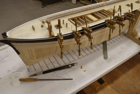
Young America 1853 – POB 1:96 Part 40 – Stern Fancy Rail 2 OK. Christmas is past and it is time to get back to work – slowly at first, starting with a POB build log update – then off to the shop. In the last part, the aft sections of the stern fancy rail were installed. In the first picture below, the starboard side section is being fitted. This piece was first shaped by tracing the outer profile along the hull – as was done for the stern pieces - then marking its width, its length, and the joint. In the picture the joint has been rough-cut and is being test fitted. You may notice that the stern section in the picture has been sanded somewhat. Actually there is quite a bit of this to be done on the top rail after bolts are installed, to match the rounded edges, etc. As long as the line against the black and the deck is left intact this is not a problem, since the top of the rail can be refinished without having to cut in the line at the edges. In the next picture the section of rail shown above has been painted and is being glued down with the help of locating pins and screw clamps. The next picture shows the clamps gripped under the mizzen channel and the main rail. In the next picture the rail on the opposite side is being installed. In the picture the leftmost clamp is closing the scarph joint in the rail. Note also that these rail sections end at the forward edge of the breast beam. At this point the rail thins down in width, so the next sections along the main deck will be narrower, but the outside line of the rail will be flush. The last picture shows the rail around the poop deck completed. The rail at the bow was installed next. Ed

- 191 replies
-
- 31
-
-
- young america
- clipper
- (and 1 more)