HOLIDAY DONATION DRIVE - SUPPORT MSW - DO YOUR PART TO KEEP THIS GREAT FORUM GOING!
×


EdT
-
Posts
2,213 -
Joined
-
Last visited
Content Type
Profiles
Forums
Gallery
Events
Everything posted by EdT
-
Thank you all for the comments and likes. I am glad to see your big smile Micheal, and of course I am always glad when druxey is smiling. Progress has been brisk and perhaps, as Allan says, the winter weather has something to do with it - snow blowing breaks notwithstanding. I don't know about fine art, Mark, but I do worship the learning curve. Ed
- 3,618 replies
-
- 4
-

-
- young america
- clipper
- (and 1 more)
-
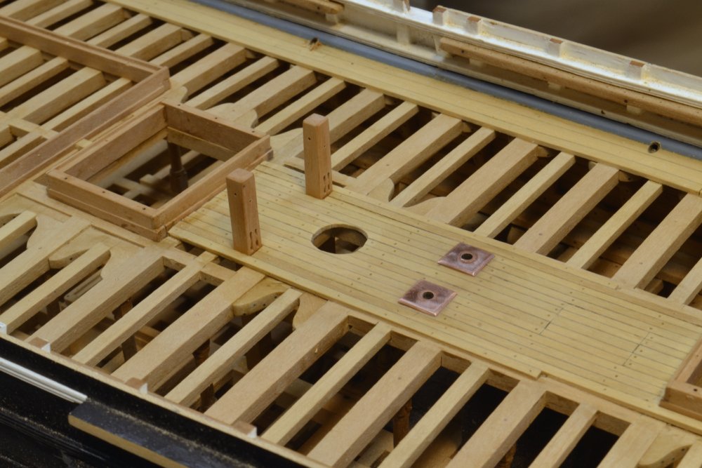
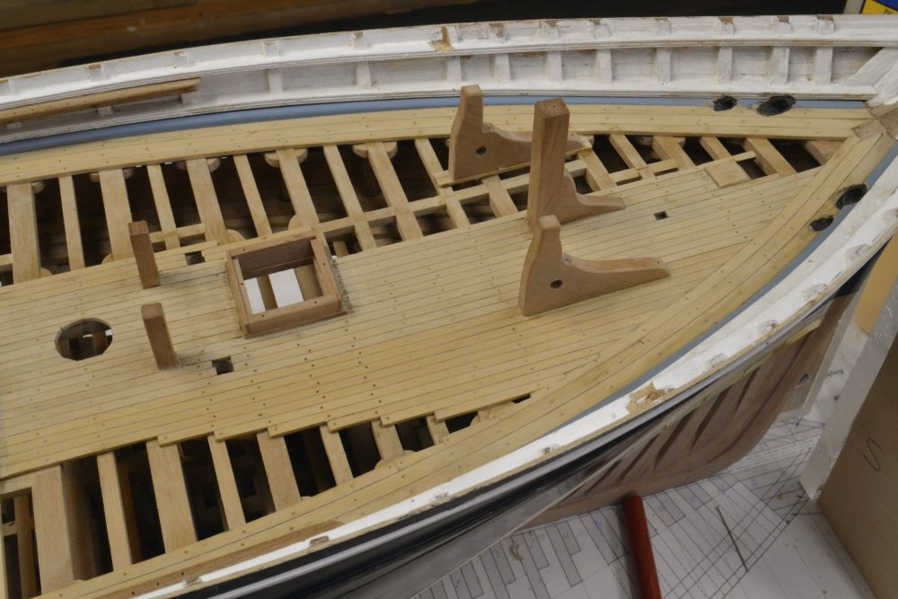
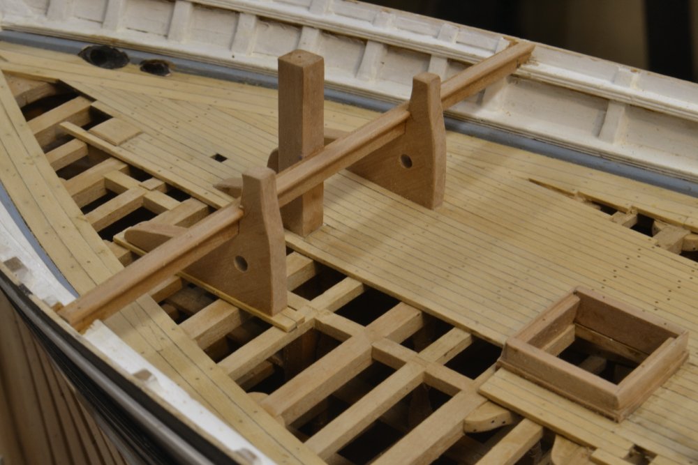
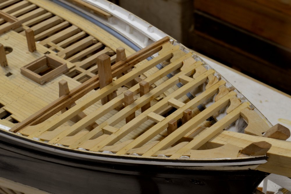
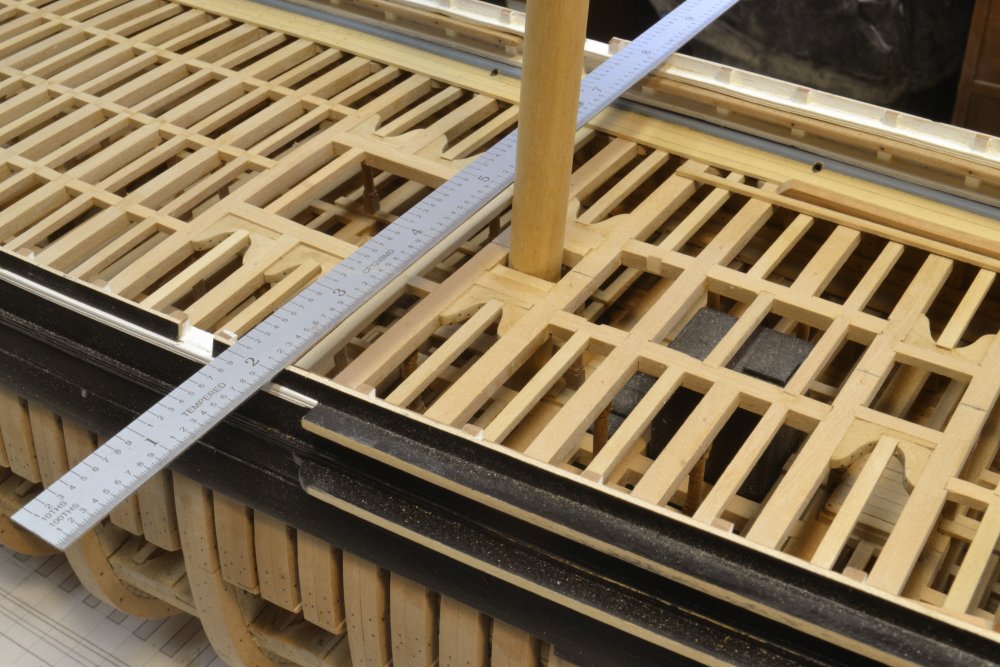
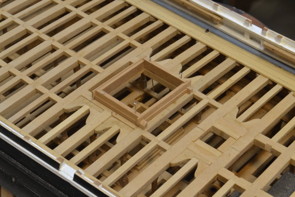
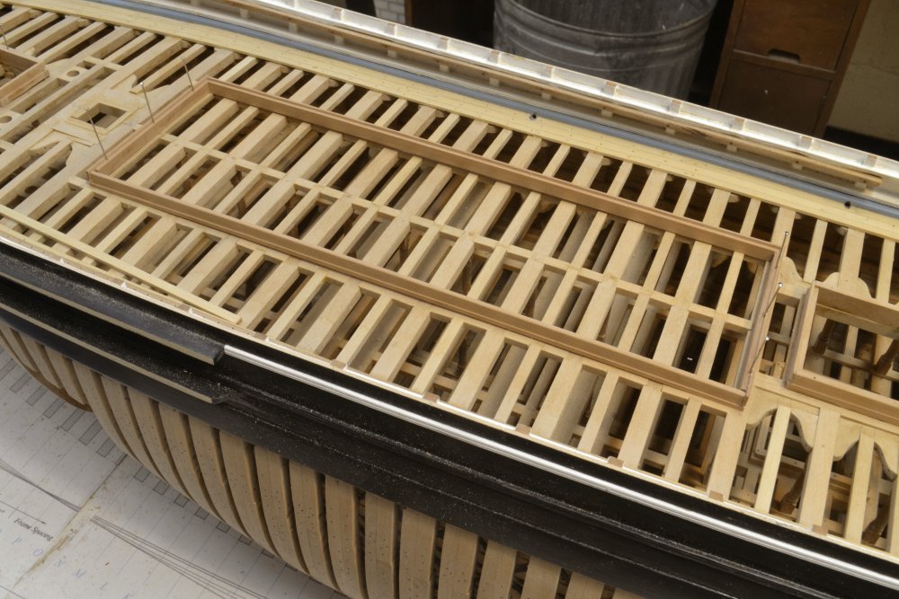
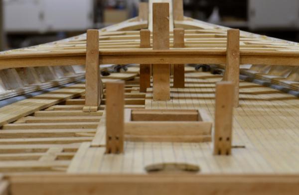
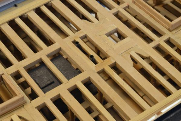
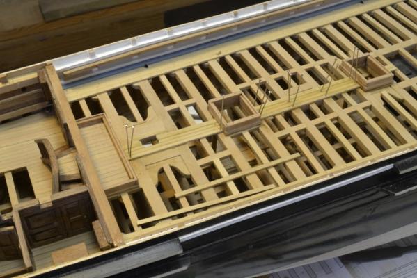
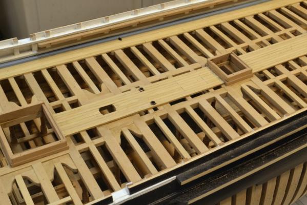
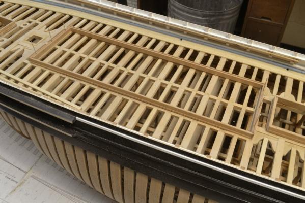
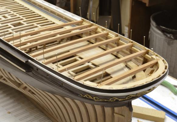
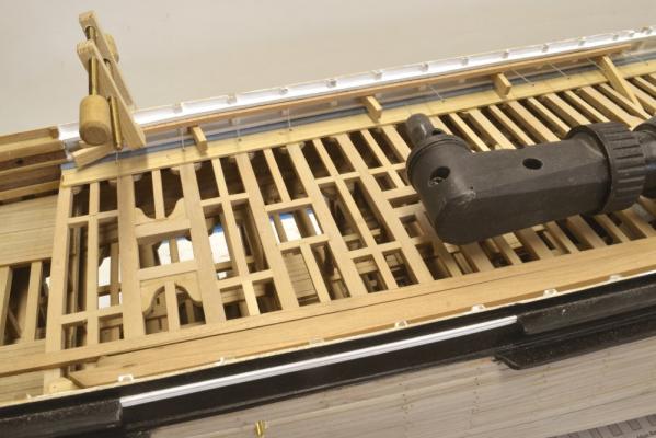
Young America - extreme clipper 1853 Part 112 – Main Deck/Forecastle Framing The first picture shows the main deck aft of the main hatch after completion of the central planking and treenailing. . Topsail sheet bits are now installed for each mast. The metal plates over the pump suction pipes will be blackened. The next picture shows decking completed at the bow. The port side in this area will be left unplanked – as shown. The starboard side was planked so the anchor chain can be shown on this side. The chain pipes have not been installed, but will come up through the two square cutouts forward of the sheet bits. The two carrick bits are installed and will support the winch later. At this stage the forecastle could be framed. The next picture shows the beginning with the setting of the breast beam. The beam is supported at the center on the carrick bits and with a bolt into the central Samson post. In the next picture the setting of the forecastle beams is underway. The top of the forecastle decking needs to be flush at the side with the top of the outer planking – and, of course, it must be fair. Fairness is being checked as each beam is set using the strip of planking as shown. As the forecastle beams were set other structures were added. In the next picture the mooring bits are being glued in. The cathead and capstan carlings have been installed. The forward beams are still loose, pending fitting of the bowsprit partners. In the next picture those have been installed along with the lodging knees and half hooks astride the dummy bowsprit. Except for carlings astride the bowsprit, the forecastle framing is essentially complete. Copper wire, epoxied bolts have been installed to reinforce the structure. The last picture is a view from directly aft along the deck. This shows the copper bolts through the breast beam. It also shows the upward sheer and the fairness of the forecastle deck. Ed


- 3,618 replies
-
- 45
-
-
- young america
- clipper
- (and 1 more)
-
Thanks, everyone. Mark, the use of coamings to improve sealing at deck partitions and to raise the height of doorsteps was probably aimed at keeping water out of the lower decks. This was of less concern on the 18C RN ships most of us have been used to - with their open gratings and ladderways. Those ships were probably pretty sodden below deck. While all wooden ships leak to some extent this would have been a serious problem on these ocean carriers that stored all manner of goods below deck for multi-month voyages. So the raised coamings - 18" for hatches on YA - as well as the caulking of hatch covers before voyages were all part of a series of practices to protect the cargo - some of which was very high value and subject to water damage. Ed
- 3,618 replies
-
- 6
-
-
- young america
- clipper
- (and 1 more)
-
Mark, Some quick hotplate test results using a surface pyrometer: 1 lb 10 oz of metal at 60 deg F 200 F at 5 minutes - began to melt at 250F Hot Plate surface 775 deg F 400F at 11 minutes - I would pour at this point - then cut back the hot plate to hold it. 500 F at 13 minutes 600 F at 15 minutes Hot plate auto shutoff - probably a hi temp safety feature 650 F at 17 minutes - should hold at this temp and I think would go higher - probably over 700F. This is obviously a lower melting point alloy and not pewter, but the heat up rate should not be different - only the melting point. This suggests you should be melting a similar weight of metal in around 15- 20 minutes. You probably only need to melt a few ounces at a time, so that would go much faster. Of course, it could be the hot plate. Hope this helps. Ed
-
Resin should not effect an RTV mold. Very hot metal will affect it over time. I believe it will make it hard and brittle. I began using lower temperature metals to avoid this problem and because its safer to handle, but I was looking for life over 100's of pours on very intricate molds more susceptable to damage. Lo temp alloys or blends that include may be more expensive, not sure, I believe $15-20 per pound?. You usually pay a premium at Micromark. I am surprised your hot plate won't melt the pewter. I have used this method for many years on various metals. I prefer the hot plate to the torch for safety reasons and also because it is easier to hold the metal at a good pouring temperature. This may be more critical on complex molds than for use on the relatively simple cannon barrels. I will do some temperature tests with my hotplate and let you know what temp I can achieve. Ed
-
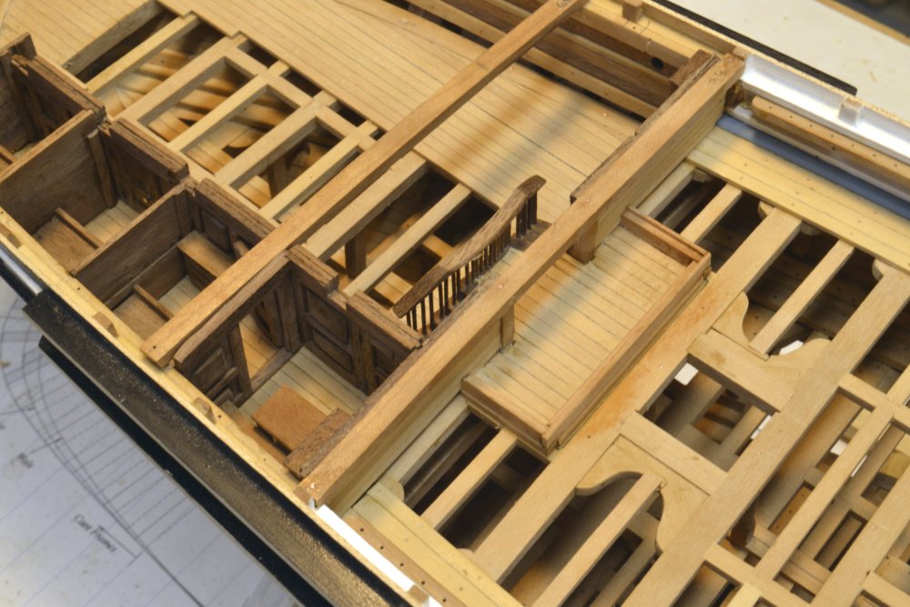
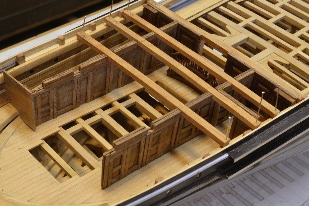
Young America - extreme clipper 1853 Part 111 – Main Deck For a change of pace from the cabin deck paneling, I started work on the main deck. In the first picture, the external, cabin deck forward bulkhead has been constructed followed by the coaming and decking inside the cabin deck entry structure. To proceed with the central decking and the hatchway coamings, the mast partners had to be first roughed in. The next picture shows the partners for the main mast being fit. The mast is a dummy – a ½" dowel fitted with a tenon on the mast step in the hold. The rake is being set with the rule at rail height based on marks made along the top strake of bulwark planking. This will all be refined later when the final masts are fitted with chocks and mast coats. In the next picture, the main hatch coaming is being assembled forward of the main partners. The cross-deck head ledges hold the fore and aft coamings down and together with angled dovetails. The excess ends will be sanded off after the coaming is glued together. It will then be permanently fixed to the deck framing. The term coaming has two meanings: the overall assembly and the fore and aft pieces. In the next picture, the two bilge pump suction pipes have been connected to their lower parts and framed in place aft of the main mast partners. The next picture shows central planking being installed starting at the mizzenmast. The next picture – from the opposite (port) side - shows planking completed forward to the main hatch. The mast openings will be enlarged later. There is a scuttle in the deck aft of the pipes to permit access to the main water tank manway below. Forward of the main hatch is the large deck cabin. Its coaming is shown fitted and pinned into place in the last picture. The foremast partners and then the chain pipe openings are just forward of the cabin. All deck structures were based on coamings similar to the hatch coamings. These could be effectively caulked and sealed to keep water out of the cargo decks below. The main deck cabin housed the crew and the galley. Ed


- 3,618 replies
-
- 38
-
-
- young america
- clipper
- (and 1 more)
-
What can I say to these comments? Only thanks. Ed
- 3,618 replies
-
- 2
-
-
- young america
- clipper
- (and 1 more)
-
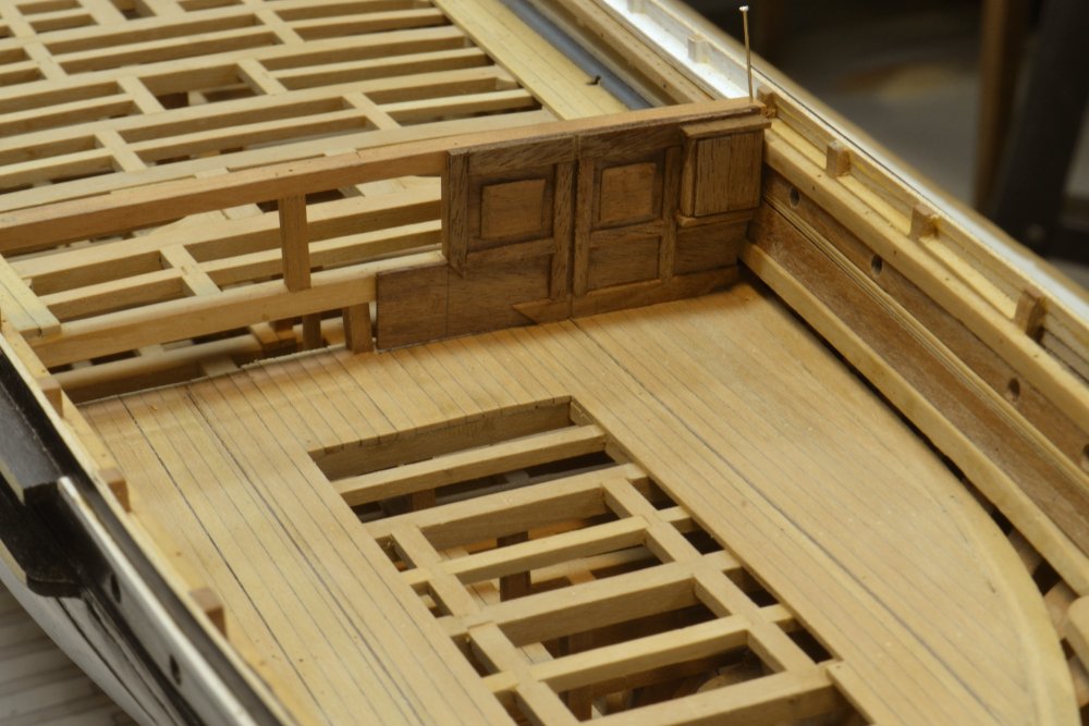
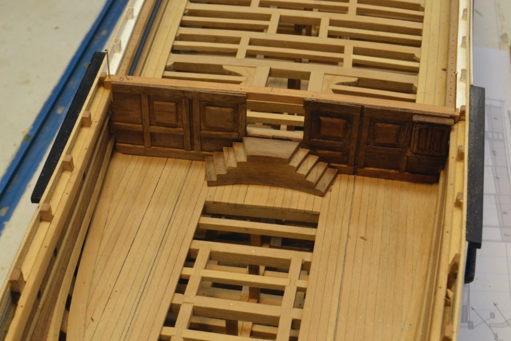
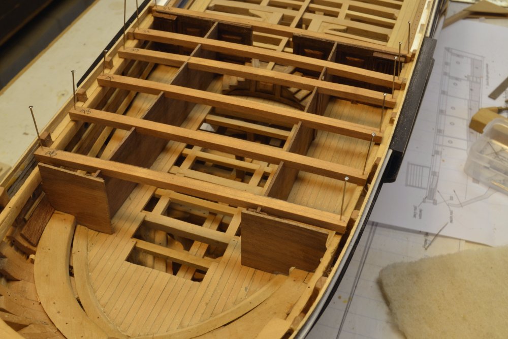
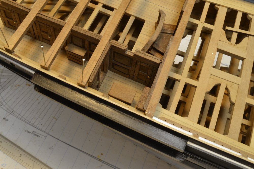
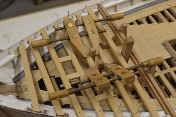
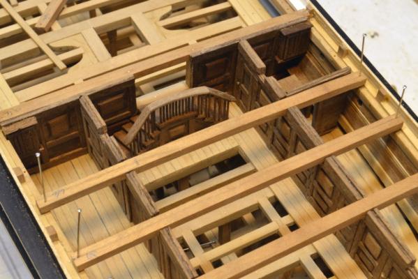
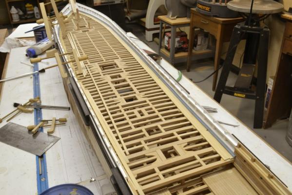
Young America - extreme clipper 1853 Part 110 – Cabin Deck Anything to avoid metal sheathing. Actually, not much can proceed on the main deck until the framing of the poop and forecastle has at least begun, so this week I have been working on the cabin deck facilities. The poop beams cannot be installed until all of that work is finished. In the first picture the poop deck beams have been made, cut to length and pinned in place. The cabin deck partitions have to be cut out around these beams so having them pinned in place is a prerequisite for the partition work. The next picture shows the first steps on the partitions. The breast beam has been glued in with pillars on either side of what will be the "grand entrance" to the cabin deck level. The central section of this beam will later be cut out so people don't have to crawl into the cabin deck. The beginning of the paneled partition shown is the forward bulkhead of the captain's day cabin with his bookcase cabinet pre-installed – but paneled doors not yet carved. We do not know what all these facilities looked like on Young America, so this is all creative design on my part – but typical of the period and the class. Some of these ships were very elegant in décor, because the few passengers carried were probably quite wealthy. I am using black walnut to simulate old mahogany for all the paneling and furnishings. Otherwise it is all going to be fairly Spartan. The first semi-indulgence in elegance is the double, curved entrance staircase from the main deck. The starting block is shown in the next picture. The panels to the right are representative of the final paneling finish. The next picture shows the perimeter walls of the cabin areas at the sides. The central "salon area" was open with tables and places to sit. Modeling of this will be limited to preserve the view into the lower regions. In the next picture the bannister of the staircase is being sanded to size after the treads, the balusters and the lower part of the rail were fitted. There will be a cap rail to cover the mortise holes for the balusters. The next picture shows the paneling of the fore and aft partitions in progress. The panels are built up using thin strips on an underlying thin sheet of walnut. The port panels are incomplete in this picture. In the next picture the capping rail on the staircase has been fitted but not yet trimmed, the paneling of the starboard wall completed and door hardware installed. The captain's cabin was traditionally on the starboard side, close to the exit to the main deck. In this arrangement his day cabin doorway is right outside the stairs. The last picture shows the inside of the captain's cabins from above. The day cabin in the center of the photo has a table, built-in bench and the book cabinet. It is quite small. A doorway to the left leads to his sleeping quarters. Only his dresser is in place as yet. In addition to the captain's palatial space, there are six other cabins for passengers and the mate. All are quite small. There will also be two small cubicles aft – a toilet and a storage space. The crew space on these ships was a large cabin on the main deck – to be constructed much later. Metal sheathing has begun, but has been held up waiting for some .002" brass. Ed


- 3,618 replies
-
- 44
-
-
- young america
- clipper
- (and 1 more)
-
Thank you, Lou. That is the paragraph I remember reading. I suspected it was in Campbell but have not had a chance to find it yet. And thank you Cog. I wondered why white lead was missing from the "recipe." Frank, this project would be nowhere without Bill Crothers and his books. Ed
- 3,618 replies
-
- 2
-
-
- young america
- clipper
- (and 1 more)
-
I'm sure I had read somewhere that the planking of the sides on these ships were planed smooth before painting, but I have not yet been able to find the reference. However, in searching, I did come across the following related to paint used to blacken wales - in Crothers: "Combine one pound lamp black mixed for paint, one pound red lead, one gallon paint oil, half pound litharge(?), and half an ounce of indigo, boiled for half an hour, and stirred at intervals. Care should be taken that the composition boils that length of time. After it has cooled a little, add one pint of spirits of turpentine; apply when warm and it will dry in a short time with a beautiful gloss, and be perfectly limber." Ed
- 3,618 replies
-
- 7
-
-
- young america
- clipper
- (and 1 more)
-
Mayflower by SawdustDave - Finished
EdT replied to SawdustDave's topic in - Build logs for subjects built 1751 - 1800
Lovely work, Dave. It is interesting that the spritsail yard braces both belay on the starboard side. Are the inner lines clues? Just curious. This era is a bit outside my limited expertise. Ed -
I am happy to see that the subject of finishes has generated comments. All are appreciated. When it comes to personal taste, there is no best answer. Its hard to measure aesthetics on a common scale, so I won't go there. Also, I am a major critic when it comes to finishes - especially my own - so I am never really satisfied. For me the paint issue has less to do with sheen than with the effect of paint on detail - moldings, planking lines, treenails, wood joints, etc. Because it obscures these things, it is not something I generally favor, however, I feel strongly that this model needs to be painted - at least partially - to convey its character. I trust that the final overall product will do that. We shall see. Ed
- 3,618 replies
-
- 13
-
-
- young america
- clipper
- (and 1 more)
-
Thank you all for the comments and likes. It is great reinforcement, especially at this time. Covering painstaking woodwork with paint can be a traumatic experience - more below. Ben, thank you weighing in and for your offer. I will send you a PM on that. Druxey, a very interesting point. I'm glad you raised it. I confess to having little insight on the finishes used originally or on the evolution of finishes in those times. It would be interesting to research this - if only time permitted! You may be correct on the use of turpentine. Solvent thinning would be one way to shorten drying time - at the expense of reducing film thickness or requiring more coats. Another approach that may have been more common would be to boil - today we say partially polymerize - the linseed or other oil as has been done for a long time to reduce drying time. This is typical in oil based paints and may go back to that era. In fact, as you say, raw linseed oil almost never dies - at least that is my experience with it. Even today, oils like linseed, Tung and maybe soya, are available in various states from raw to highly polymerized. There are also products adulterated with dryers. So, who knows? Not me. Deciding on the level of gloss put my brain on overtime, so I will drone on. It is interesting to note that with the acrylics that I used, increased dilution gave a flatter finish - to the point where I had to mix enough to do the full job or there would be differences. In any event, I did not rely on the dried finish per se. The final appearance was developed by rubbing - 0000 steel wool, then white grade Scotchbrite, then rottenstone with water. This dulled the initial paint gloss - my father used to call it "cheap gloss" - to a deeper, less shiny look. This also helps remove dust particles and other imperfections - although there are still many left, especially in the moldings and in crevices that cannot be rubbed much. These made me long for a flat paint. I'm not completely satisfied, but I am finished. It probably looks more like a model than the original ship. Today I'm going to start plating the bottom. Thanks, again for all the comments. Ed
- 3,618 replies
-
- 5
-
-
- young america
- clipper
- (and 1 more)
-
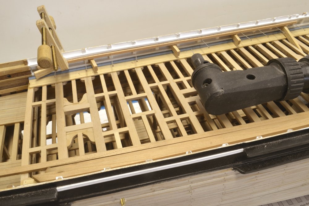
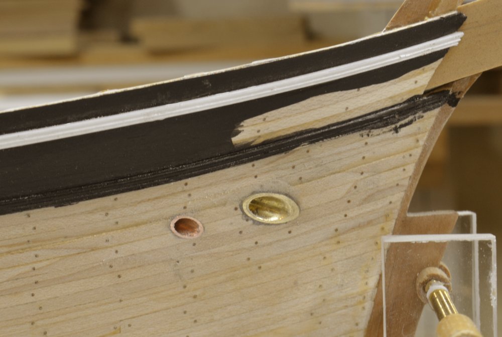
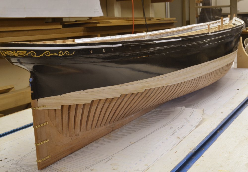
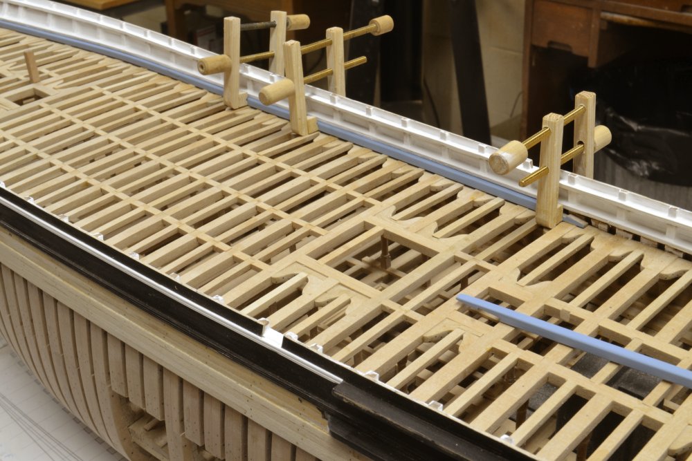
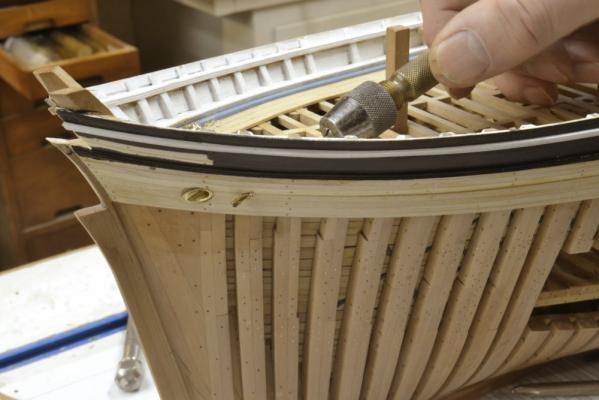
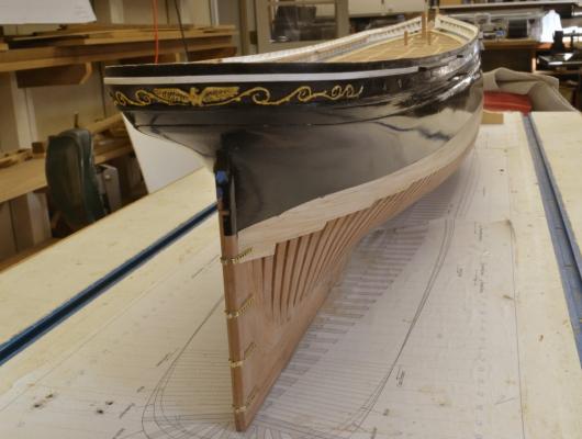
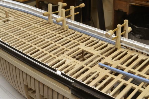
Young America - extreme clipper 1853 Part 109 – Pin rails/Hawse holes/paint Since the last post, the four long pin rails were made and installed. The first picture shows one being pinned in position. These fit up under the main rail and are glued and bolted to the toptimbers. Paint was filed off these first. The rails are cherry. Most of the main deck natural wood structures will be of this species - slightly darker than pear. The pin hole drilling was aided by the right angle drill in the picture. The wood blocks help keep the rail up until the pins are in. In the next picture the rail is ready for glue. Before the hull could be painted, scuppers and hawse holes needed to be fitted. In the next picture the hole for the smaller of the two hawse openings is being drilled out. These openings are parallel to the keel on the lines from the chain tube openings on the main deck. They slant down to emerge at the correct position on the outside. Small pilot holes were drilled then enlarged to fit metal tubes. The tubes are shown in the next picture. After fitting, they were epoxied in, sanded off flush and rounded off. They will eventually get painted red. All of this was in preparation for painting the hull below the planksheer. This consumed most of the time since the last post – reminding me why I prefer not to paint models. My father used to say painting covers a multitude of sins – until it dries. He was right as usual. This is especially true with gloss finishes. The next picture shows the finished starboard side. The paint is fluid artist’s acrylic, thinned and applied in several coats over acrylic sanding sealer, then rubbed out when dry between coats. Why gloss? I may be wrong, but I do not think flatting agents for paints were invented until the 20th century. I am sure in 1853 the paints were linseed oil and lampblack – or white lead for the white. Definitely gloss but probably not this smooth. In any event, the hulls of these clippers were usually finished as smooth as practical given their size. The last picture shows the view from the stern. The planked area below the black on this side will be metal sheathed – once I get comfortable with the paint finish. The planking on the port side extends only a few strakes below the channels – no sheathing required. Ed


- 3,618 replies
-
- 48
-
-
- young america
- clipper
- (and 1 more)
-
Highlander has the answer. The spools are 100 meters. That should be several lifetimes worth of bolts. I buy one spool. Ed
-
This is what I use, Alan. http://stores.ebay.com/AMNESIA-FISHING-LINES/AMNESIA-FISHING-LINES-/_i.html?_fsub=1149399010&_dmd=2&_nkw=black Ed
-
Have no fear, Alan. I know I am fighting decades of model shipbuilding practice in my disdain for rubber cement. I don't like the messy brush or the rubbery residue it leaves on the wood and there are times when it does not adhere. It requires solvent for cleaning and its shelf life is limited before it turns into rubber. I only use it when I have to. Its right above contact cement on my list - something else I have to use sometimes. I'll take my 29 cent Elmer's glue sticks any day for paper on wood. Looks like you are off to a good start - long way to go. Cheers, Ed
-
Very nice work on the drawings, Alan and the table looks terrific. Although I am no fan of rubber cement, I look forward to the beginning of your construction with great interest. Good luck with the project. Ed
-
Thank you all. Greg, this is a case where some input from others, encouraged more effort on my part. I am much happier with the last result. Thanks. Ed
- 3,618 replies
-
- 1
-
-
- young america
- clipper
- (and 1 more)
-
HMS Victory by EdT - FINISHED - 1:96 - POB
EdT replied to EdT's topic in - Build logs for subjects built 1751 - 1800
Thank you, both for these comments. Victory seems like ancient history to me, but I am glad if you have found some value in the posts. It was certainly a training ground for me. Ed -
Richard, thank you for that explanation. If my math is correct, the lancets are about .007" in diameter - about half the diameter of the syringe I was using. Its very useful to know about these very tiny tubes. thanks, Ed
- 3,618 replies
-
- 1
-
-
- young america
- clipper
- (and 1 more)
-
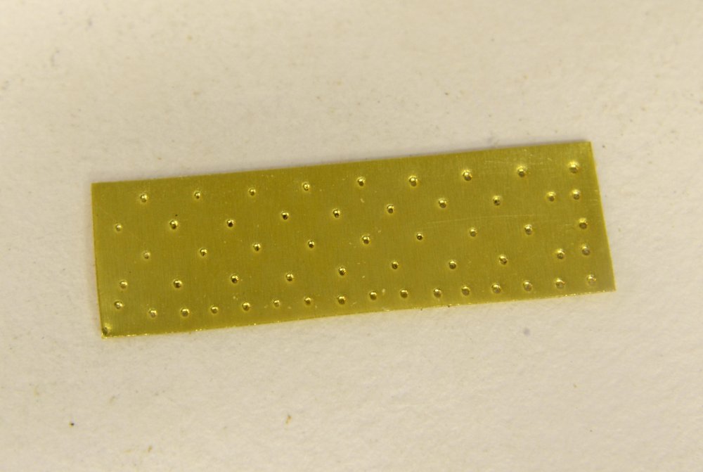
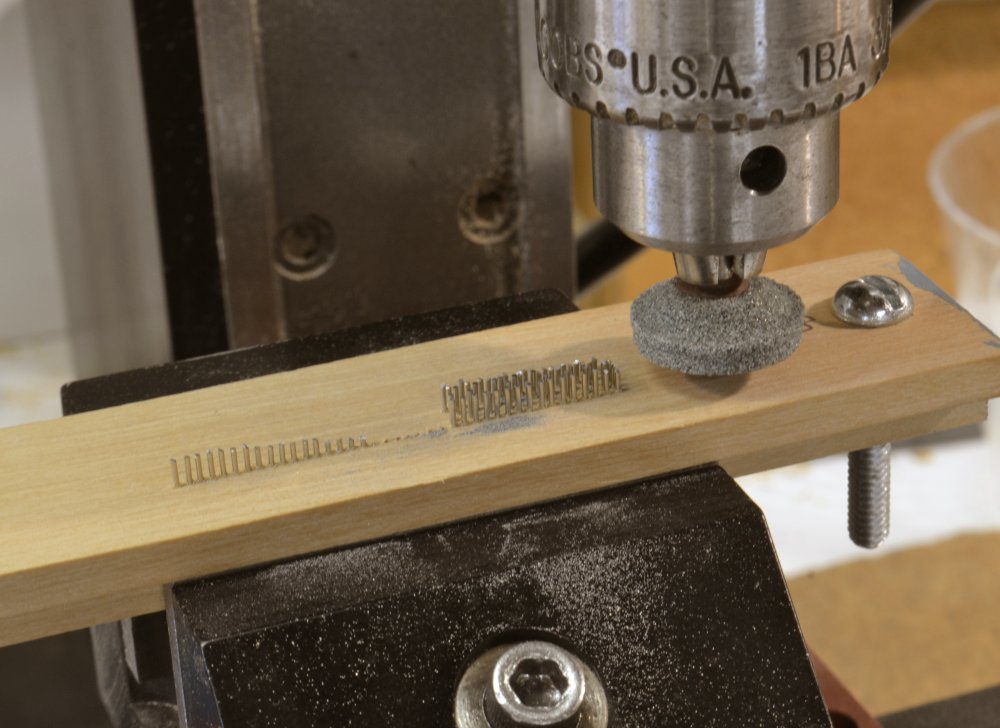
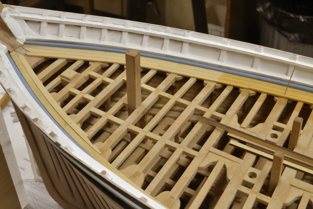
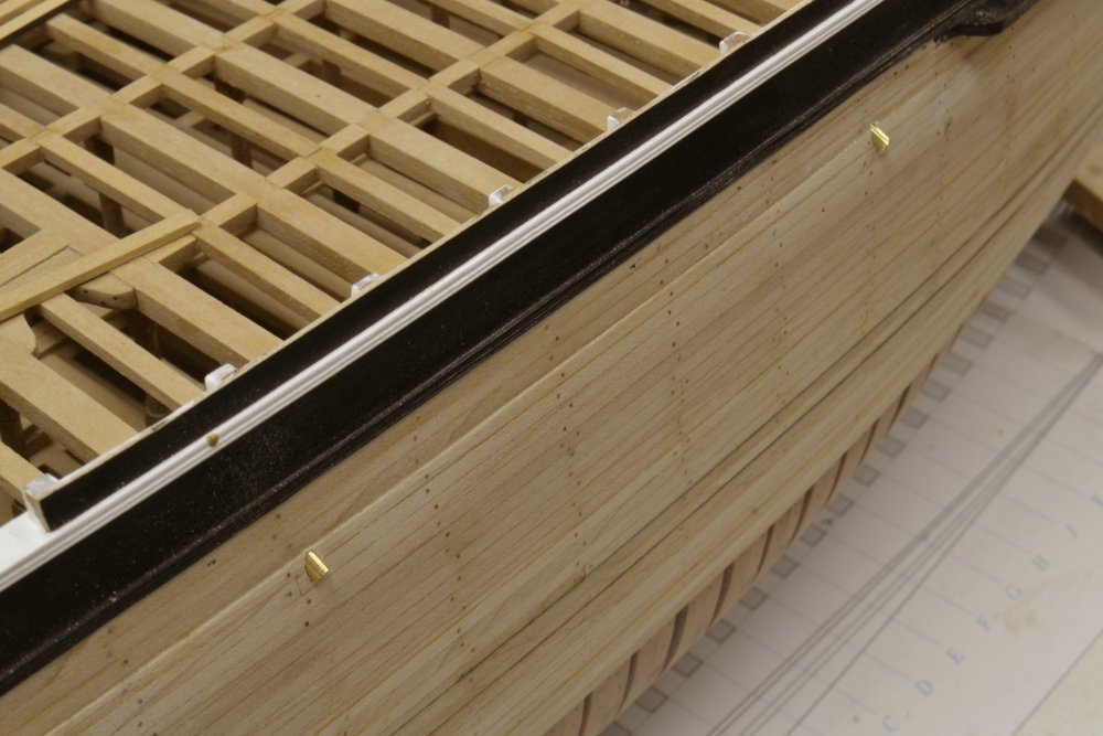
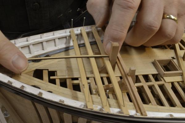
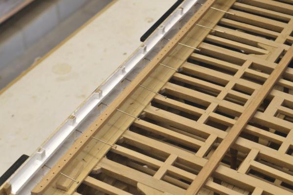
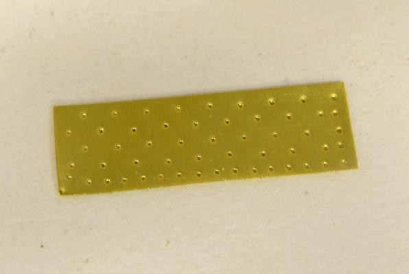
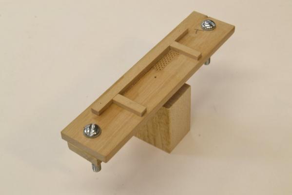
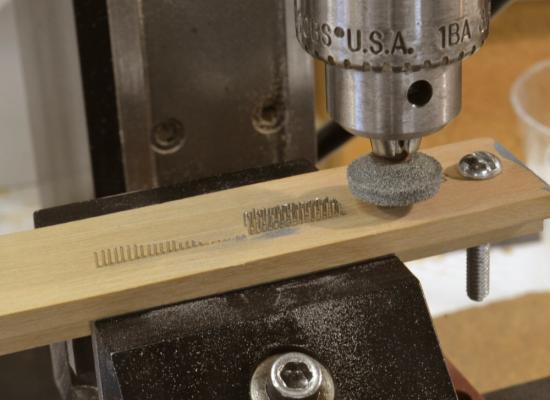
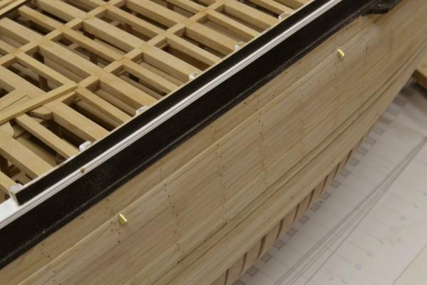
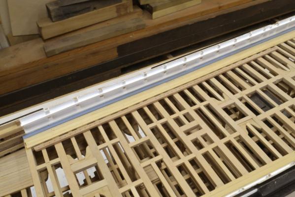
Young America - extreme clipper 1853 Part 108 – Sheathing plates/Deck members Well, those brass plates I showed in the last post certainly sparked a lot of interest – and helpful comments. Even as I posted those photos I was thinking about improvements. The comments convinced me and provided some good ideas. One of the final plates is shown in the first picture – an ultra- closeup. This has a very close duplicate of the original nailing pattern. The sheets would have been pre-punched – perhaps like this one – then simply placed in position and nailed over a tarred felt covering. In the lower row, the indentations are about 3” apart, so you can see that the dimples themselves are less than an inch I diameter – just about right. This plate is 48” x 14” (about 0.67” x 0.195”). The model plates are .002” thick brass. The next picture shows the stamping fixture – sitting on the block of hardwood used to stamp the brass. The top piece is drilled to accept .018” straight pins – a sliding fit. A fence is added to align the plates. The top row of holes is extended so the “dress course” (top row) can be stamped a second time so those plates will have nail rows top and bottom. A brass plate is sandwiched beneath the top piece and a lower piece as a hard support at the bottom of the pins. After drilling the nailing pattern the two blocks and the brass plate were bolted together. Pins were inserted and clipped off. These were then machine ground down to a few thousandths above the wood surface to make them a uniform length – as shown below. With the pins still in the holes, the parts were disassembled and reassembled with the plate under the ground off ends of the pins. After testing on some plates, the pins were wetted with thin CA to keep them from falling out. The fence was then added. The lower block is held in a vise for stamping. Small dimples are best achieved with a hardwood block tapped lightly over the plate. I expect to describe this process step by step in the book. All of this was a bit of a side show because I am not yet ready to sheath the hull. The main event this week has been the installation of the waterways and binding strakes on the main deck. The first picture shows the starboard waterway being glued against the frames in between the beams and the planksheer rail. After forming these pieces and fitting the scarph joints, they were painted light blue before being installed to avoid have to “cut in” the painted line by hand – too shaky for that. The next picture shows the two 10” wide binding strakes and the “nib strake” being installed on the starboard side. The top of the outer binding strake is about 6” above the beams, the inner binding strake is tapered so the inside edge is the height of the common planking – 3 ½”. The nib strake is that thickness and 8” wide. The planking at the side will be limited to these three strakes. There will be central planking between the hatchways. The next picture shows the starboard side complete and work in progress on the port side. Some of the starboard scuppers can just be seen in the above picture. The next picture shows these being fitted through the outer planking. These will be filed off flush and blackened before final installation. The remaining hull planking can then be painted and the sheathing installed on the starboard side. The pencil lines in the picture define the height of the dress course. The last picture shows a pin rail drilled and shaped but not yet installed. These rails will fit right under the main rail. Paint has been filed off of the top timbers under the rail so the pin rail can be glued. Ed

- 3,618 replies
-
- 31
-
-
- young america
- clipper
- (and 1 more)