HOLIDAY DONATION DRIVE - SUPPORT MSW - DO YOUR PART TO KEEP THIS GREAT FORUM GOING!
×


EdT
-
Posts
2,213 -
Joined
-
Last visited
Content Type
Profiles
Forums
Gallery
Events
Everything posted by EdT
-
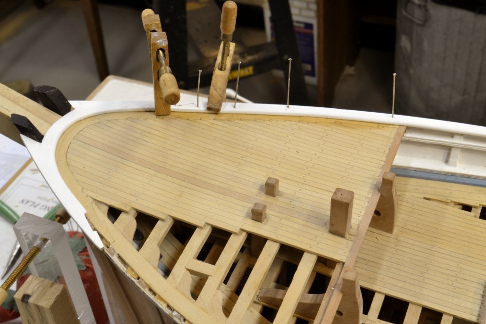
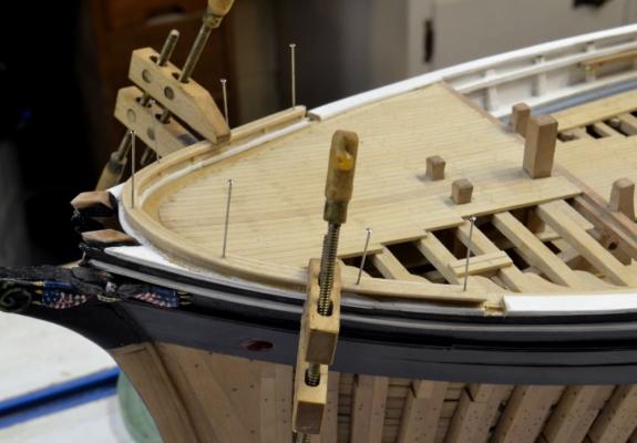
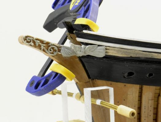
Young America - extreme clipper 1853 Part 118 – Chain Pipes/Catheads/Topgallant Rail Not a great deal of progress to report – just trying to get the model to the scope of volume I of the book. The first picture shows the second chain pipe being inserted. These reach down to the hold where the chain was stored. From these openings the chain was run forward around the winch to the hawse holes. In the next picture blanks for the catheads have been fitted. The fancy rail is cut out where these pass through. They will bolt through carlings on the inboard ends and into the framing at the side. While sheaves were being cut into the catheads the pieces of the forecastle topgallant rail were cut, boiled and put into the fixture shown below to dry. The rail will consist of a central bulwark plank with strips attached to the top on either side to simulate a thin top rail – much easier that to bend the 2” rail on its edge. Sanding and painting make it look like a single rail – much like the multi-part rails along the sides. In the next picture the rail has been assembled - including short stanchions on the inside – and is being glued to the fancy rail. Paint was scaped from the fancy rail for this. The topgallant rail was then bolted through the pinholes, finish sanded and painted – as shown in the last picture. This picture also shows the finished catheads installed – with their American plaque emblems painted on the ends. Ed

- 3,618 replies
-
- 42
-

-
- young america
- clipper
- (and 1 more)
-
Great work, E&T. I'm dizzy from all the pictures. The precision of your work is superb. Ed
- 346 replies
-
- 3
-
-
- terror
- polar exploration
- (and 2 more)
-
Rob, I have not starting thinking about masts yet, but from what I have seen so far, I believe at least the lower masts would have been made masts. Ed
- 3,618 replies
-
- 1
-
-
- young america
- clipper
- (and 1 more)
-
Thank you all for these comments and all the "likes." To answer your question, George, the joints are cut by hand using a razor saw and a good quality barrette file - no fixtures and no high class machinery. There are patterns for the poop deck transom and the stern section of the fancy rail to assure the correct curvature. The margin plank was cut to fit. The aft sections were made first with their hook scarph joints. The joint on the next section at each side was then cut to fit that - by eye with marks. This takes some care and attention to the grain direction, but I believe most modelers could mange this. All is being described in the book in excruciating detail. Just a word on the book: These last pictures show the model almost to the state that will be covered in Volume I. We are working pretty hard to have this out by fall. Ed
- 3,618 replies
-
- 3
-
-
- young america
- clipper
- (and 1 more)
-
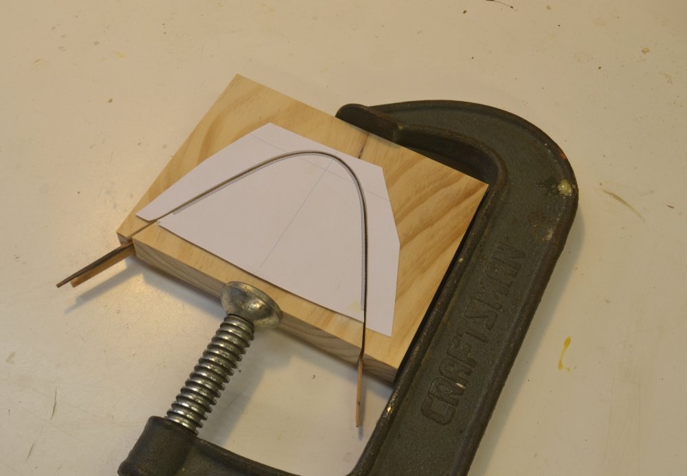
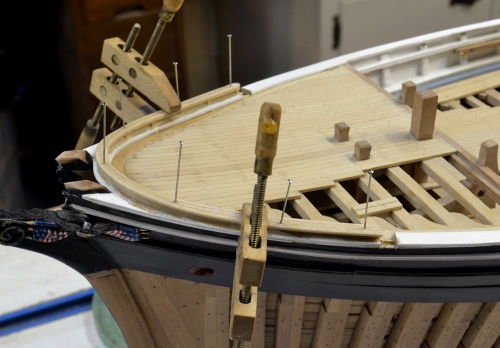
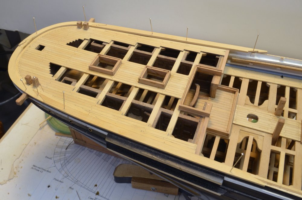
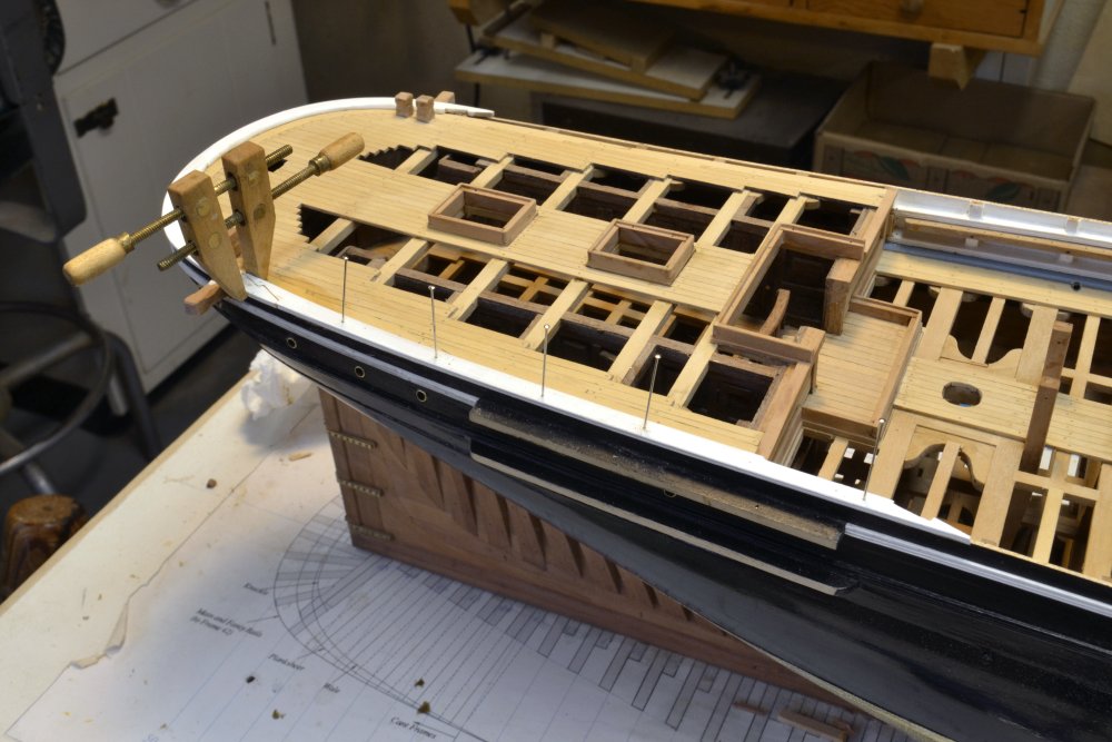
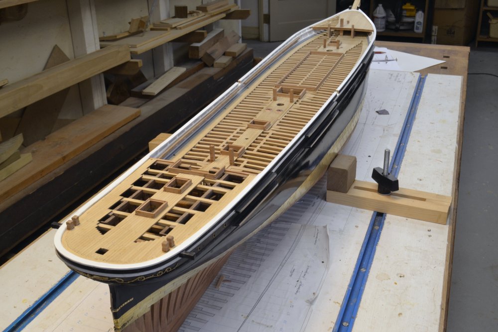
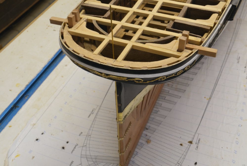
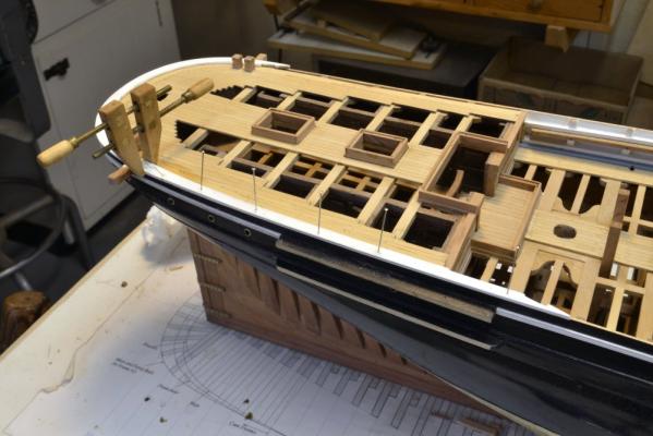
Young America - extreme clipper 1853 Part 117 – Poop Deck/Fancy Rail In the first picture, the aft section of the margin plank is pinned in place against the tops of the stern timbers. This piece has a hook scarph on each end. The rudder post will be cut off later. This picture also shows the framing of the boomkins and aft mooring bits. In the next picture the next section of margin plank is being fitted to the hook scarph on the aft section and around the mooring bits. In the next picture the poop margin planks have been fitted forward to the breast beam and the aft sections of fancy rail are pinned in place. The fancy rail forms a cap over the stern timbers, deck margin plank and the top strakes of planking around the stern. The coamings for the two skylights are pinned in place for fitting the head ledges. In the next picture, the poop deck has been planked – leaving open areas to view the cabins underneath – and the skylight coamings are in place. The fancy rail has again been pinned in place. To keep water out of the cabin deck this had to be caulked inside and out. To have sufficient overlap of the poop margin plank, it was made 15" wide – as on the forecastle. I stepped these rails down to 12" along the main deck. The next picture shows the painted parts of the fancy rail being installed. The step down in breadth on the forward piece can just be seen at the break of the poop in this picture. I spent quite a bit of time deciding how to handle this fancy rail width issue. Most midship sections show a narrow rail – about 12" – but I finally decided this would not provide sufficient overlap of the poop and forecastle margin planks. So, another one of those judgment decisions. The next picture shows the fancy rail fully installed aft of midship. After painting, the sections were glued and pinned. As the pins were removed, copper wired epoxied bolts were installed down into each toptimber to reinforce the attachment. The bolts were filed off and the top of the rail received more finish painting. And the next picture shows it at the bow. The last picture shows the model with the completed fancy rail. I have been looking forward for a long time to the capping off of those toptimbers. Ed


- 3,618 replies
-
- 60
-
-
- young america
- clipper
- (and 1 more)
-
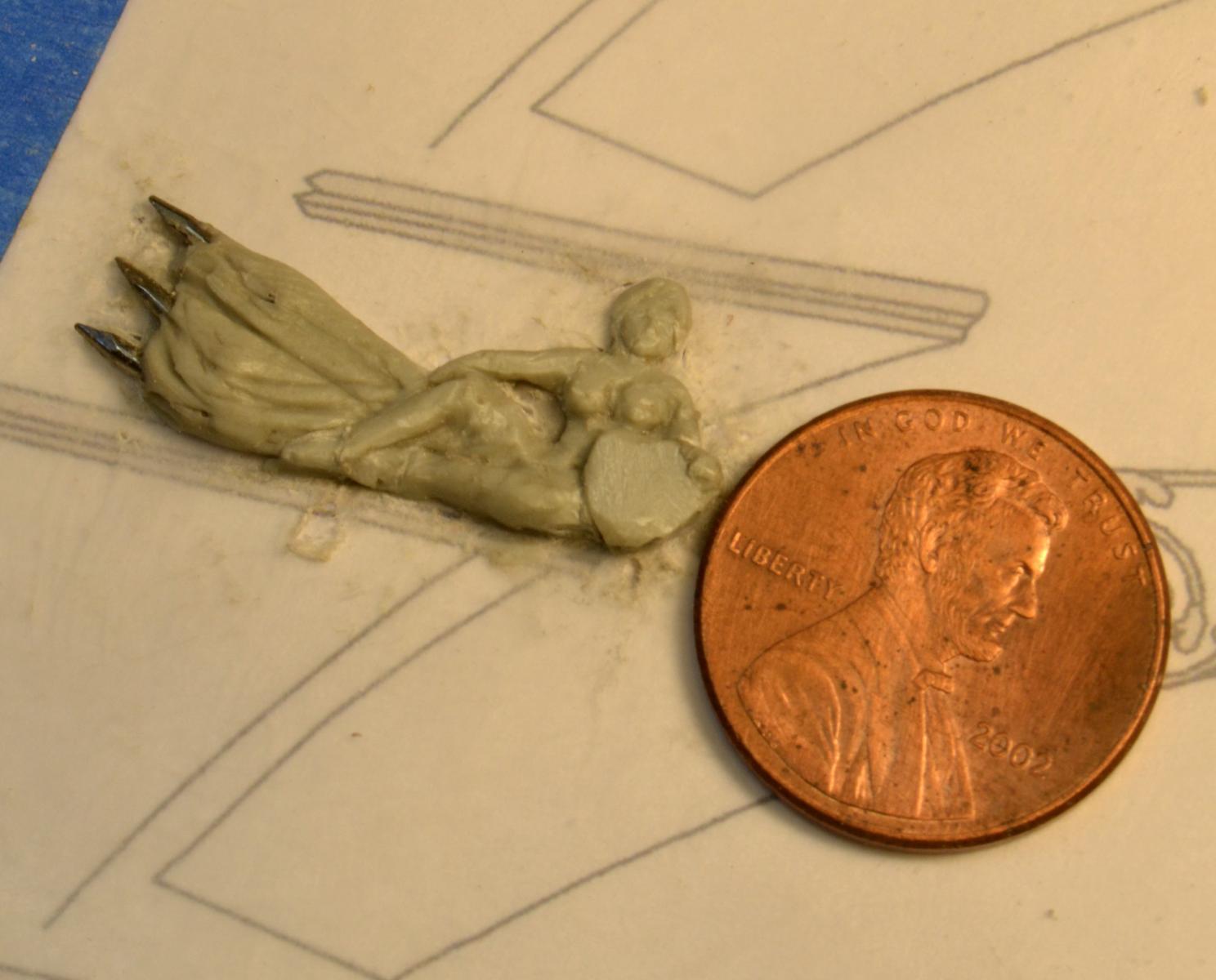
Thank you, all. George, I have not used Sculpey, but I believe it is dried or cured in the oven. I do not know if it an epoxy, but it may be. I know it is commonly used, so others may comment. Magic Sculpt is a two part epoxy sculpting material. It hardens slowly over about 24 hours without heat. This can be accelerated with warming, but it is usually better to let it cure at ambient conditions. AS it begins to firm, it can be worked in different ways. For example, it is often easier to indent eye sockets when the material is stiffer - especially if you have shaky hands as I do. I did not utilize that on these figures. They were all made in one go. The material also responds well to moisture. Wet brushing or rubbing can leave a silky finish. I use the natural - grey green colored - type. I have tried the white, but it works somewhat differently. I have also tried other epoxy types - including Milliput, but found MagicSculpt to work best for me. Here's a link: http://www.magicsculp.com/ Ed
- 3,618 replies
-
- 8
-
-
- young america
- clipper
- (and 1 more)
-
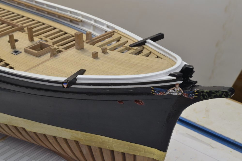
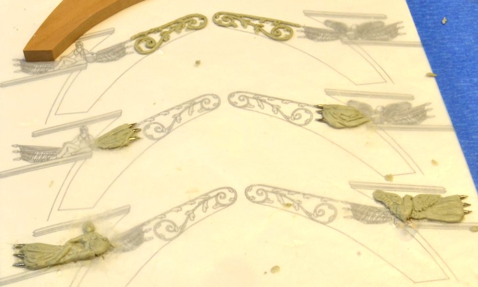
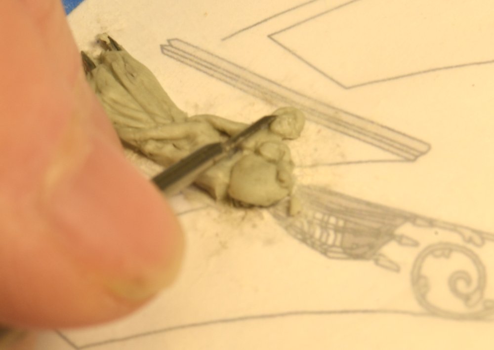
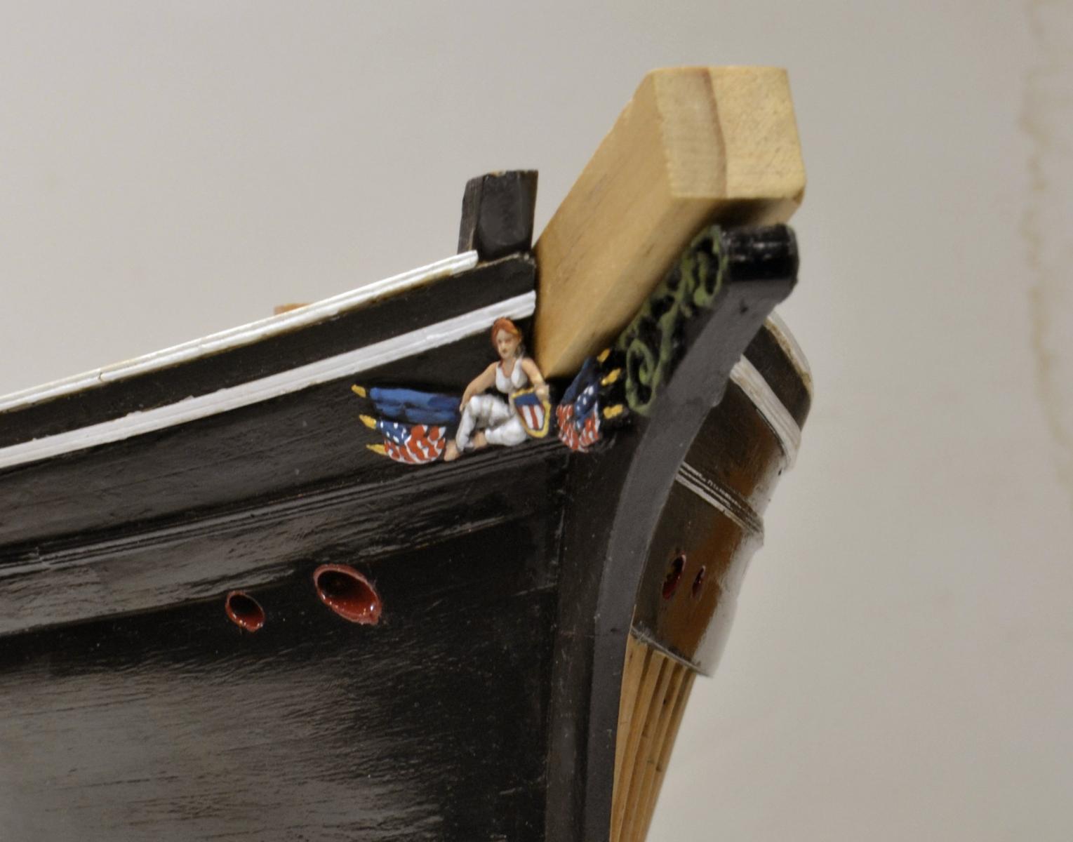
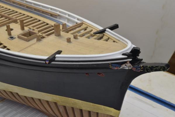
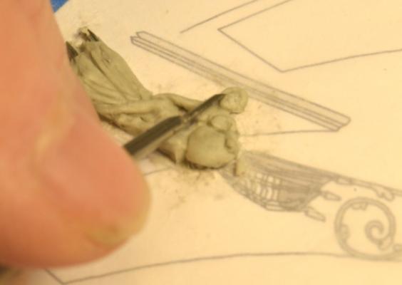
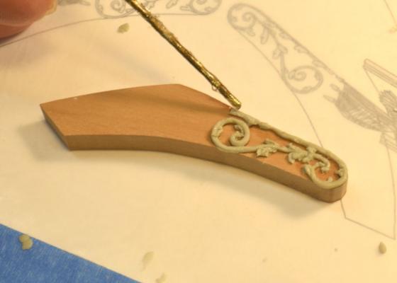
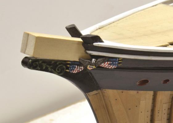
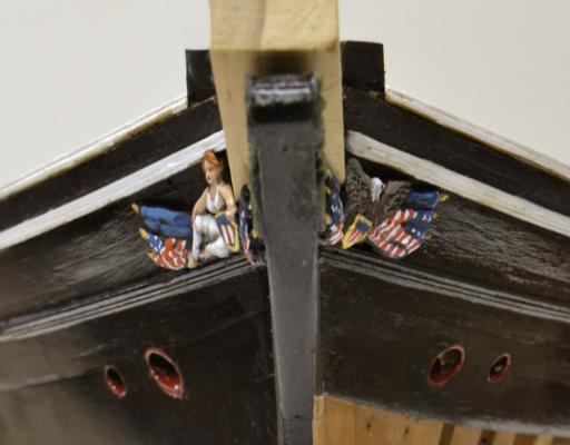
Young America - extreme clipper 1853 Part 116 – Bow Decoration Young America's bow decoration is interesting for a number of reasons. Each side is different. Just aft of a billet decorated with greenery, the carved figures rest mostly on the waist planking and partially on the base of the billet. There were no headboards, so it is not clear how these were mounted on the original ship – much less how to mount them on the model - due to the angle between the two surfaces. Also, unlike the gilded stern decoration, the figures at the bow were painted in natural colors. All this, like many other aspects of the ship, is based on Bill Crothers research. After some unsuccessful attempts to fashion a wood base in the angle, I finally decided to sculpt these as six separate pieces, then fit them together on the bow. The first picture shows the initial figures, sculpted with MagicSculpt® on wax paper taped flat on the pattern sheet. The figures are quite small. The starboard side features a female figure – presumably Liberty – with a shield flanked by draped flags. On the port side an American Eagle is substituted for the female figure. Below is the sculpted female figure before any post-hardening refinement. The points on the flag staffs are thumb tack points. The next picture shows some refining of the sculpture using a very small chisel. In the next picture the fragile greenery has been lifted off the waxed paper, laid on the billet and touched with a drop or three of thin CA. Refinement of the greenery was done after being glued on. In the next picture the three port figures have been fitted and glued on with CA. The figures were set into soft sculpting material placed in the angle between the billet and the side, than pushed into a fit. Some modification of the parts was needed for this. The sculptures must leave clearance for the square bowsprit to slide in and out. Excess material was removed. After attachment, the figures were primed with thinned flat black enamel. The entire hull was given one last coat of acrylic paint and the figures were painted using acrylic gouache. The next picture shows the starboard decoration. The next picture shows the port side. The greenery is actually brighter with light highlights than shown in the photos. The next picture, from dead ahead, shows both sides. Photos like these and closer ones were very helpful in judging the paint job and suggesting improvements. The model went back and forth a few times for these. The acrylic gouache used for painting the figures dries dead flat, causing an almost two dimensional appearance in the photos – especially in the close ups. I may give these a coat of semi-gloss medium, perhaps the acrylic sanding sealer I used over the stern lettering. Speaking of that, I received the second order of dry transfers, so I was able to correct the letters that were photo shopped in the last post. The last picture shows the repaired letters – unadulterated. This picture was taken before the final repair on the C. After repair the dry transfer letters were given a coat of diluted sanding sealer. I am also quite happy with the final black finish on the hull – shown in this picture. With all this work done, the lower framing was given a last coat of wax, so the model should not have to be inverted again, I hope. This will allow me to get on with work on the upper deck – cabins, etc. Ed


- 3,618 replies
-
- 49
-
-
- young america
- clipper
- (and 1 more)
-
Bill, Young America was equipped with a moonsail on the main mast - a 26'-4" yard. With her original single topsail rig, this would have been the sixth sail. With her later double topsails it would be the 7th. Both surving photos of her show double topsails and no moon sail. These were probably taken in the 1870s or 80s. Rigs were often - usually - determined by captains or owners - sometimes in spite of builder opposition. Some were even influenced in their original construction by captains assigned to that by owners. A famous example is the assignment of Rob Waterman - perhaps the most famous of captains - to the construction of Webb's Challenge. As was common with captains, Waterman insisted on excessive sparring. This may have accounted for her less than stellar performance on the first voyage. She did much better under later captains. Sparring usually evolved after original construction as a ships' performance became better defined. Excessive - and dangerous - over-sparring was a common occurrence with the extreme clippers. Many of these lofty rigs - and the men on them - were carried off by the wind. Ed
- 3,618 replies
-
- 2
-
-
- young america
- clipper
- (and 1 more)
-
That certainly is quite enough for any day, Micheal. Bravo! Ed
-
Thanks, again, everyone for all the comments and likes. Nils, the sheathing is my least favorite job, so I am glad not to have decided to do the entire bottom. It is very bright right now, but I am hoping it will dull down some. Maury, there is one porthole in each cabin to give some light and air. I do not know if YA had ventilators. There are two large skylights over the main cabin area, so I am sure it was quite bright - and airy if they were opened. Can't comment on the rudder, but I suspect it was sized adequately but no larger - to minimize drag. Kees, no, I am only working for myself, but these days the employer is a slave driver. Far from perfection, Crackers. I do intend to rig the model, but no sails. It will probably be as in the picture - with double topsails. Yes, Mark, it is an attempt at button tuck green velvet upholstery. The bare wood bench looked very plain. The one resemblance I can attest to is that the button tucks fill up with sawdust the way my desk chair collects stuff. I stopped short of doing bed mattresses however. Unfortunately, part of yesterday - after the post - was taken up in dismantling and replacing the starboard boomkin and mooring bits due to a measuring error. It showed up when I was fitting the margin plank. Thanks, again for all the interest.
- 3,618 replies
-
- 6
-
-
- young america
- clipper
- (and 1 more)
-
Thank you, all. Druxey, I had that same thought about storage behind the paneling. That kind of space could well be used for passengers' baggage. There was certainly little space for that in those tiny cabins. All of this arrangement is speculative on my part, as is much of the stern framing detail. While typical, that framing, may not have been accurate for Young America. That is one of the reasons I am not keeping it visible. Another reason is to deck the aft part of the poop for the wheel and the helm housing that covered the rudder machinery. Ed
- 3,618 replies
-
- 2
-
-
- young america
- clipper
- (and 1 more)
-
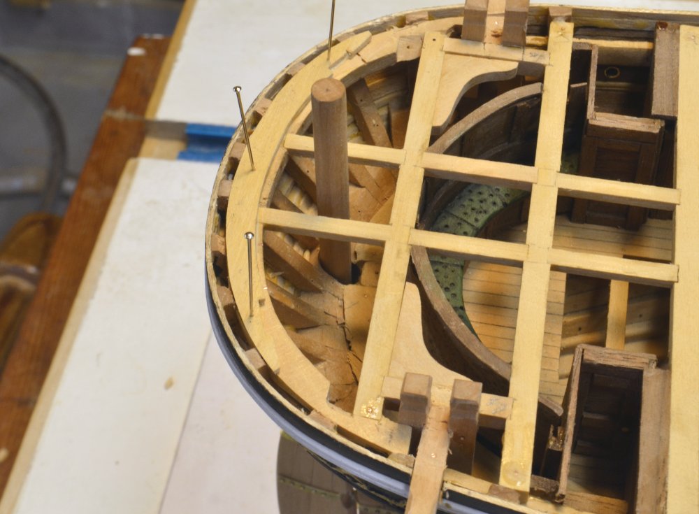
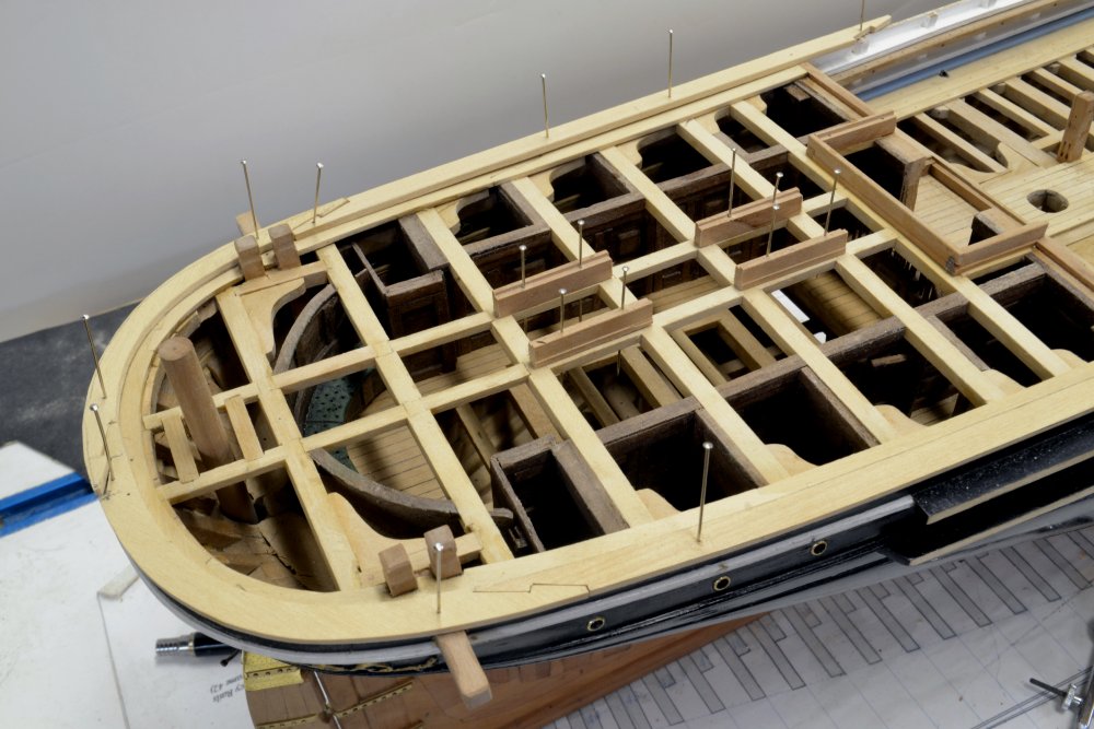
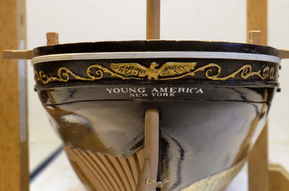
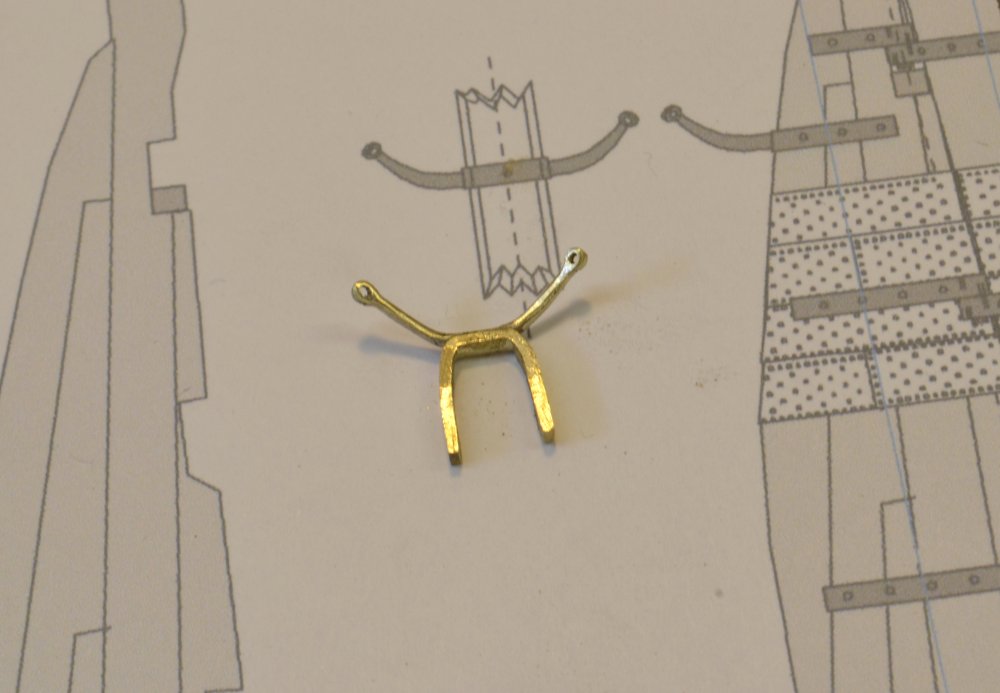
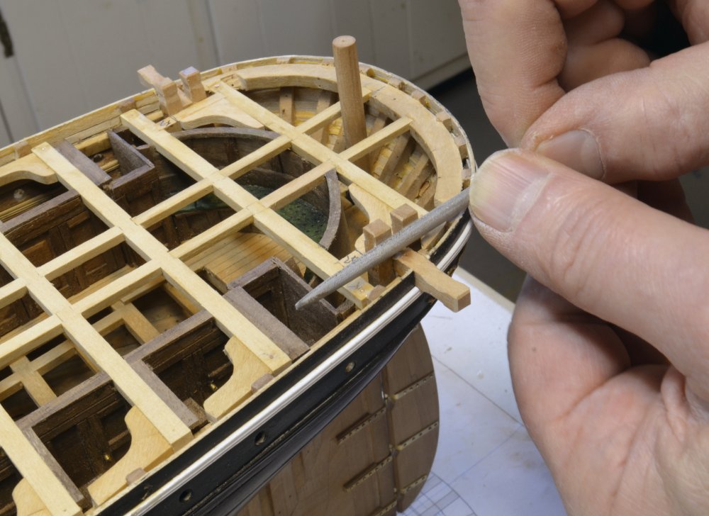
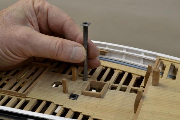
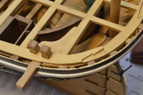
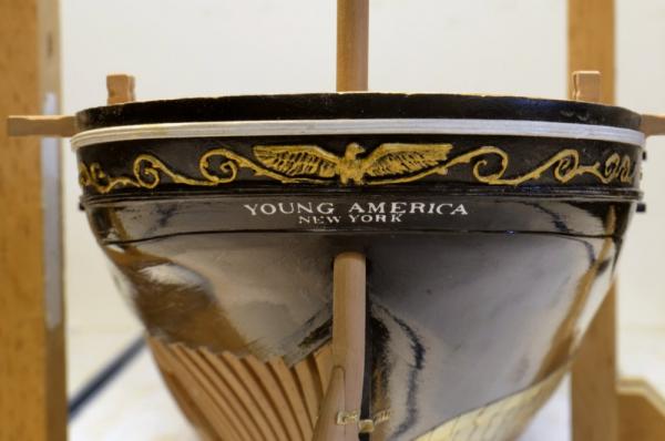
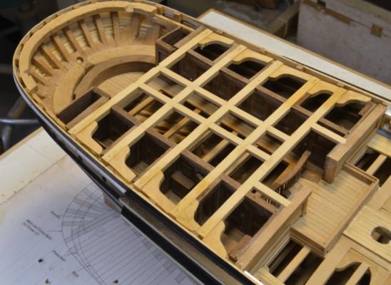
Young America - extreme clipper 1853 Part 115 – Rudder, Miscellaneous The first picture shows the last bit of work on the interior cabin deck detailing. The curved seat/partition separates the cabin from the stern framing and leaves room for the rudder shaft. All of this structural work aft of the partition will be hidden under poop decking. As can be seen in a later picture, I decided to cover this rather austere seat with some upholstery. With this in place the framing of the poop deck could be completed, including the fitting of the aft mooring bits and the boomkins shown in the next picture. These are 12" x 12" timbers, tied together and into stout carlings that I reinforced with knees as shown. The helm port was previously drilled through the framing but now had to be drilled through the bottom planking and sized for the 16" diameter rudder shaft. After drilling a pilot hole, the center of the full hole could be set with a still wire through the gudgeons as shown below. The hole was carefully enlarged with round files to fit the rudder. The next picture shows the rudder hinges being fitted. The gunstock shaped rudder rotates on the axis of the wire in the previous photo. The top gudgeon has been added over the paint. The hinges were fit one-at-a-time. The masking tape is to keep the woodwork clean of metal dust. The dry transfer stern lettering can be seen in this picture. It is not yet finished. The G, C and K need to be replaced and I am awaiting delivery of some more letters. However, the picture below shows what it will look like. I say what it "will" look like. In the interest of full disclosure, I did a small amount of "photo shopping" on the three broken letters so I could use this picture. Please excuse this. The letters are quite small – 3/32" and 1/16". When I get the replacement letters and successfully (hopefully) place them, the lettering will be sealed – probably with acrylic sanding sealer. Right now they are easily scraped off. I did a lot of that. The next picture shows the fabrication of the iron rudder preventer in progress. There are four parts – silver soldered. It has rather long horns. These have been rough shaped. The strapping still has to be thinned down and drilled for bolts. The blackened preventer can be seen below on the installed rudder. The preventer was blackened with WinOx. I have now disposed of all my remaining blue stuff in favor of this. The rudder post in the next picture will be cut down later. The mooring bits and boomkins are being shaped in this picture. I found it easier to do this after installation – using rounded files. The last picture shows the present state of the stern. The poop deck is now ready for its two skylight coamings and decking. Note that the portholes have been installed, All of the work on the lower hull is now complete and it has been finished with wax. Ed


- 3,618 replies
-
- 47
-
-
- young america
- clipper
- (and 1 more)
-
Wonderful work, as ever, Micheal. I don't know what else to say except that I am enthralled by your work. I kmow that like yourself, the rest of us are dying to see it run. Cheers, Ed
-
Looking great, Mark. You may be able to buff the barrel a bit with a soft cloth to give it some metallic sheen. Are the guns going to be set at deck height or beam height? Ed
-
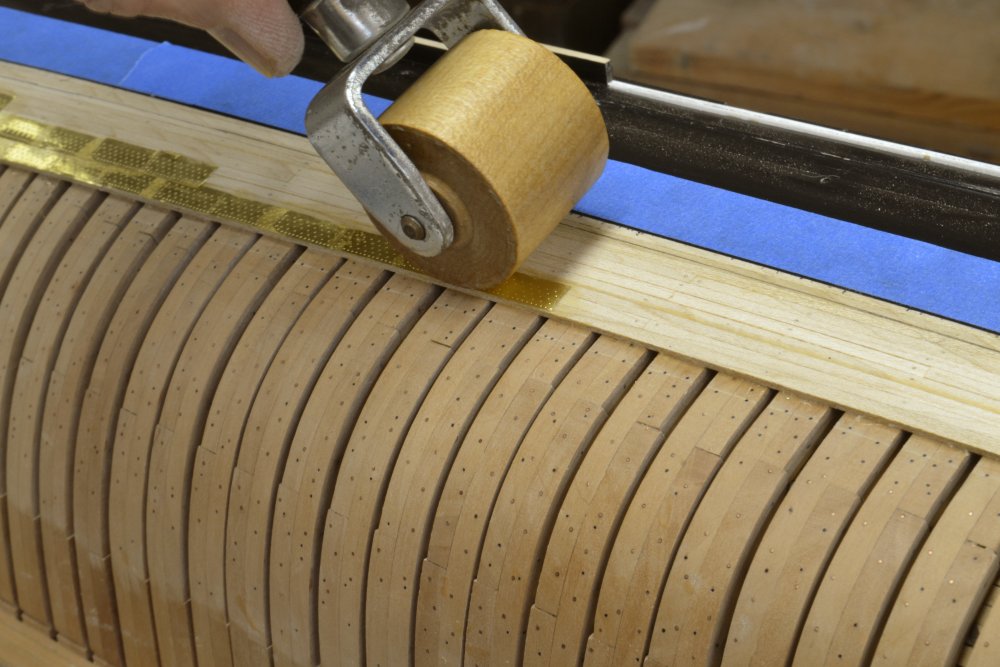
Thanks, guys. Druxey, the grey Scotchbrite was cut to make a 1 - 1 1/2" circular disk, then fitted to a mandrel. The edge was used to buff - very lightly - just enough to knock down some of the brass glare - 5 minutes for the whole area. All excess cement removed first. With the disk rotation down and aft, no problems picking up edges or corners. The roller and having glue under the entire plate have the edges secured pretty well. To pry some of them up for repositioning, I had to use a chisel to get a corner lifted. With the indentions going in, the surface is very smooth. Ed
- 3,618 replies
-
- 5
-
-
- young america
- clipper
- (and 1 more)
-
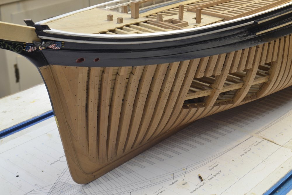
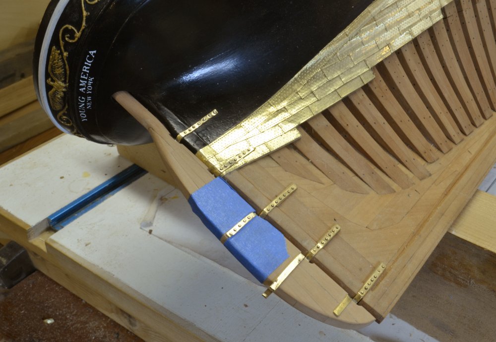
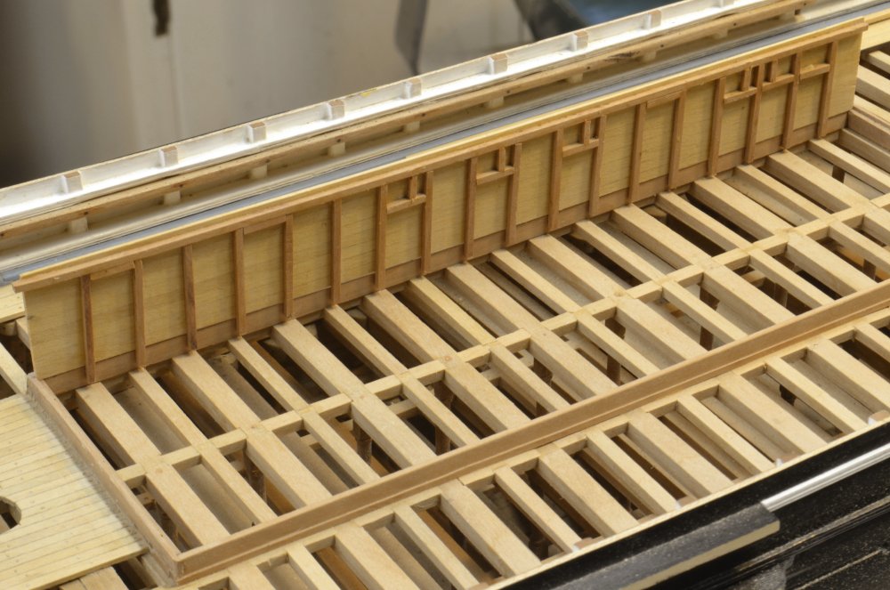
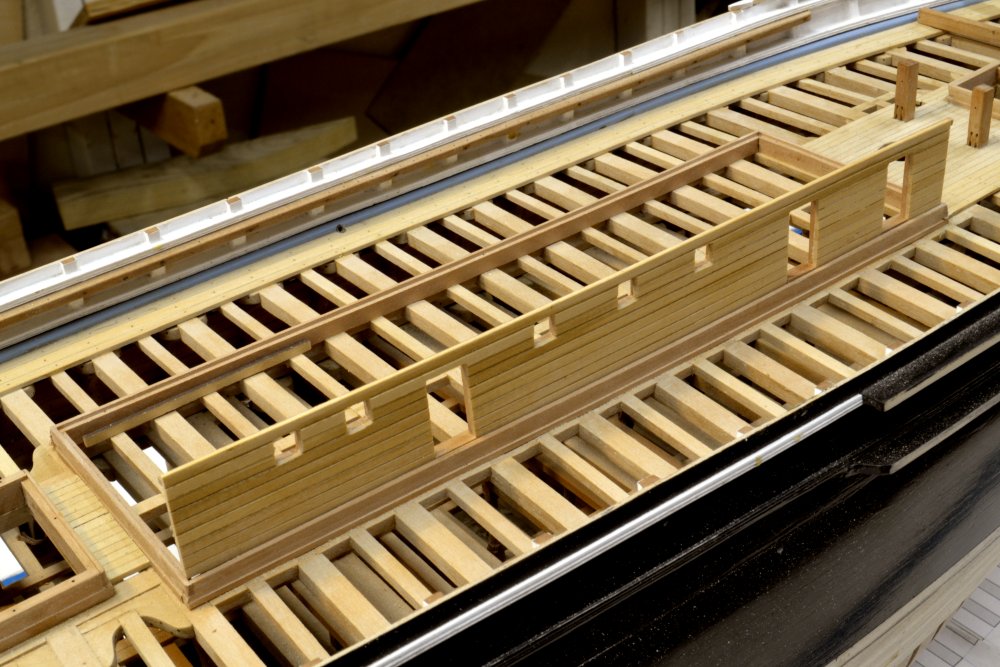
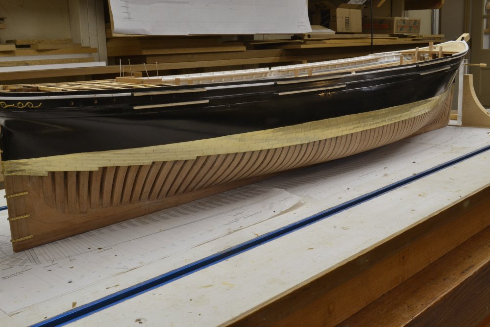
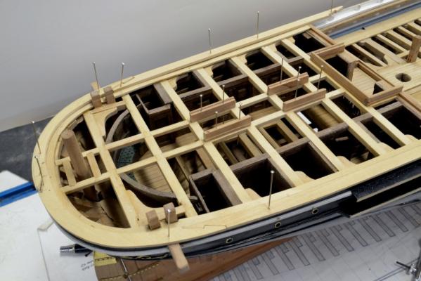
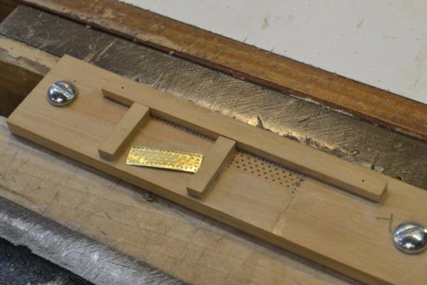
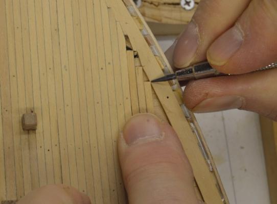
Young America - extreme clipper 1853 Part 114 – Cabins, Brass Sheathing With the forecastle essentially complete, I returned to the interior of the cabin deck. The first picture shows the cabins on both sides completed. The poop deck framing has been installed back to the last cabins. The curved wood block that will serve as the base for the circular seat and paneling is set in place. This will close off the aft end of the cabin deck, separating it from the stern framing and the helm. Note also that the double doorway into the cabin deck has been cut – once the poop framing was done. I also started work on the main deck cabin. The starboard fore and aft wall panel is being constructed in the next picture. The panel was made first from individual planks. It has to follow the sheer of the deck. In the picture the 4X4 plate that will support the roof rafters is glued on and 4X4 studs are being attached. The next picture shows the framed wall in place for a trial fit. The doors and windows have been framed on the inside. In the next picture they have been cut out. The exterior walls will be white. I will do this painting before fitting the natural wood framing of the doors and windows. This has all been a nice diversion from the brass sheathing of the hull, but I did not want to proceed further with details on the main deck without finishing the lower hull to minimize the need to upending the model. The next picture shows the stamping tool for embossing nails on the brass plates. This was discussed in some previous posts. The area on the right is used to stamp every plate. The single row stamp to the left is used for the top dress course. It needs a row of nails added at the top. The plates are cemented down with contact cement, with the indentations up to simulate nails hammered into the plates. These should more correctly be called sheets. They were very thin. Being nailed over a felt underlay would have left a decidedly quilted appearance. In the next picture, a plate has been cemented and is being rolled down. This improves the bond with the contact cement, presses down the edges, and flattens out the indentations. Glue is applied to one plate and its place on the hull at a time. This is necessary to have glue on the overlaps. Excess cement that can be seen on installed plates in this picture is easily removed later. The last picture shows this work completed. The brass is very shiny. It will dull with time, but I helped it along with some buffing with a Scotchbrite disc in a rotary tool – just enough to dull the glare a bit. Work on the bottom framing can now be completed – adding any missing bolts, blackening the copper wire bolts, final poolishing and applying wax finish. It may also be time for the stern lettering. Ed


- 3,618 replies
-
- 48
-
-
- young america
- clipper
- (and 1 more)
-
I second everone's remarks, Micheal. Ed
-
After saws, chisels are the premier woodworking tools. That is why I included the appendix on making them in Naiad Volume I. I normally only use one or two - both straight types - but they are always out of the toolbox. On the joggled planks I used a chisel on the margin plank and the disk sander on the planks. David, acrylics can be airbrushed, but cleaning acrylics out of the airbrush can be a pain. Its not like watercolor or solvent based material. I have airbrushed models - not ship models - with acrylics, enamels and Floquil - always in a small ventilated hood. Air brushing is an acquired skill with a learning curve - as you may know. I did not use it on YA for fear of overspray in places that would be impossible to clean. I recommend a good brush for these models. Micheal, I would take more overall photos, but that means cleaning up the shop. Its bad enough having to sweep away clutter to take some of the close ups. Thanks again for all the comments and likes. Ed
- 3,618 replies
-
- 6
-
-
- young america
- clipper
- (and 1 more)
-
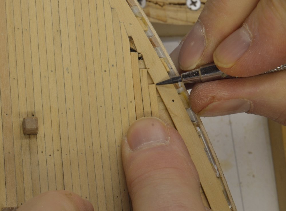
Thank you all very much for all of the positive reinforcement. I hoping she will be ready for launch - meaning hull completion - in a month or so. Greg, to answer your question, the 14" wide margin plank was installed first with uncut edges. Planking was worked out from the center - 6" wide planks. Central planks were mitered at the end until the angle of the cuts reached about 45 degrees. Before installed the last mitered plank, it was laid in place to mark the intersection of its outer edge with the inner edge of the margin plank. Before installing the last mitered plank, a cross cut - one-half plank width - was plunge cut with a chisel or hobby knife into the side of the margin plank. The unshaped joggled plank was then laid in place to mark its intersection. The angle of the joggle was then cut with a chisel between the two marks. After fitting the last mitered plank, the first joggled plank was tapered at the end to fit the joint. Before installing it the margin was marked in the same way for the next plank. Below is a picture showing the marking of some later planks. This process was fast and worked well. If I were doing it again, I would make the forward curved piece of the margin plank shorter so its scarphed joint would occur before the first joggled plank - to avoid having to joggle a plank into the scarph. It never too late to learn.
- 3,618 replies
-
- 35
-
-
- young america
- clipper
- (and 1 more)
-
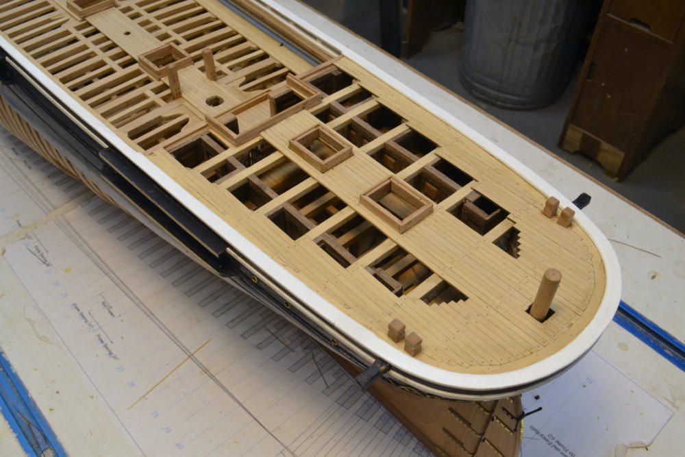
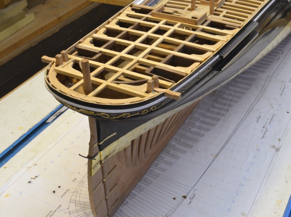
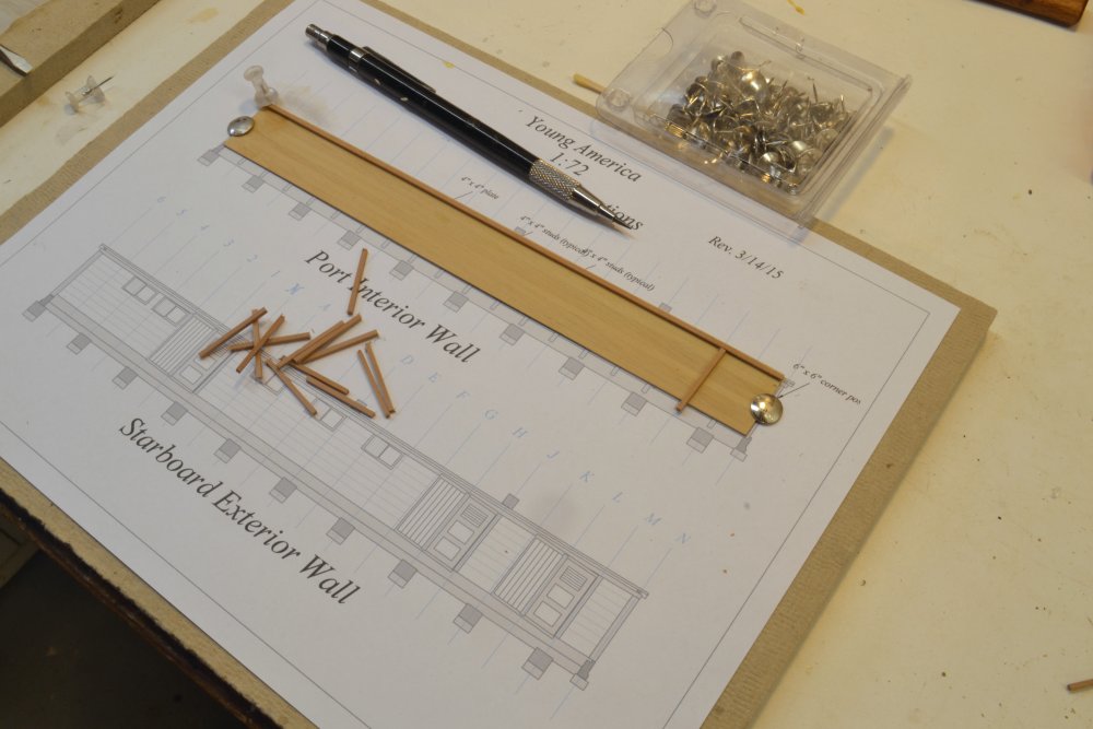
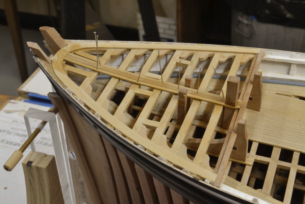
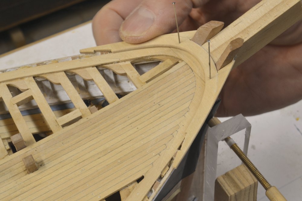
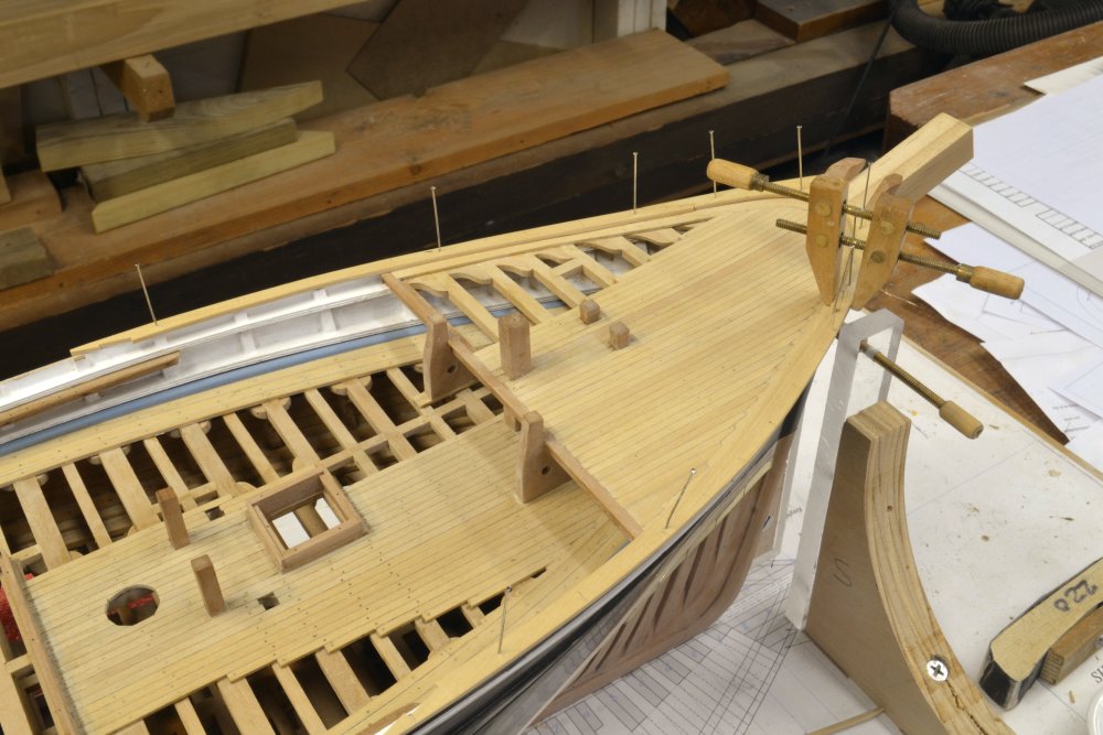
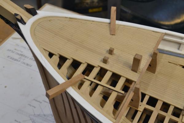
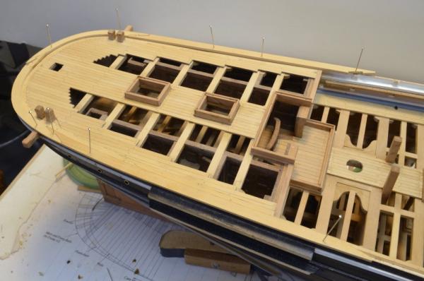
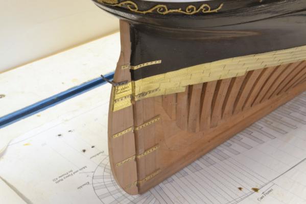
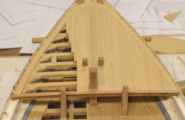
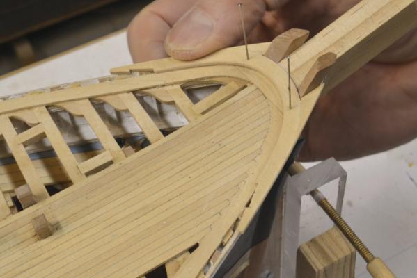
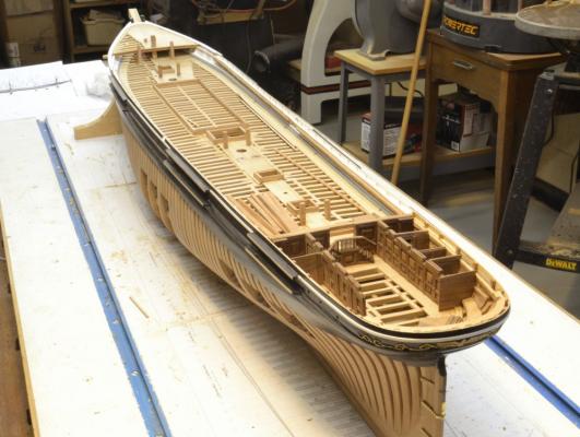
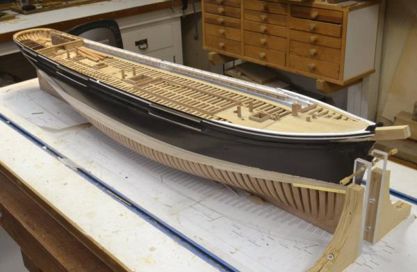
Young America - extreme clipper 1853 Part 113 – Forecastle The first picture shows the margin plank on the forecastle installed and planking started along the centerline. The next picture shows the completed planking – as yet untreenailed. In the next picture the forward end of the fancy rail has been made and is being fitted around the knightheads. The adjoining pieces of the fancy rail are being fitted in the next picture. In the next picture the sections of fancy rail have been painted white and are being glued down. All treenailing of the forecastle deck has been completed in this picture. The last wo pictures are of the full hull – as requested. I have to do quite a bit of clutter removal to take pictures like this. This picture also shows some progress on the port side cabins of the cabin deck at the stern. The last picture is from a different angle. The part below the black will be plated. The bowsprit is just a dummy. The channel edges are unpainted because cap moldings will eventually be glued to these edges. Ed


- 3,618 replies
-
- 38
-
-
- young america
- clipper
- (and 1 more)
-
I should have emphasized the word acrylic because acrylic gouache is not as common as the gum arabic, water-color variety. I have been using it for so long that I often forget that. Jack, gouache and gesso are two completely different animals. As druxey points out above, gouache is an opague water thinned product, traditionally very much like watercolor but very opaque. Acrylic gouache, much less well known, uses an acrylic emulsion as its binder making it water resistant when dry and more durable. Like the traditional type it is also thinned with water. Ed
- 3,618 replies
-
- 3
-
-
- young america
- clipper
- (and 1 more)
-
Normal gouache will dissolve, of course. Acrylic gouache does not, since it has an acrylic binder. A number of manufacturers now offer acrylic gouache - I use Jo Sonja, but their are others - Turner for one. These are highly pigmented and dry dead flat. Rowney started making these, I believe, in about 1970 while I was living in the UK. A few years later they were off the market. Acrylic gouache made a comeback perhaps 25 years ago. They are very versatile. I used them diluted to color the rigging on my Victory model. They have proved very durable on the miniature figures, even with frequent handling. Ed
- 3,618 replies
-
- 1
-
-
- young america
- clipper
- (and 1 more)
-
druxey, My rationale may not be completely sound on this, but it worked, so here it is: I wanted to build up the final finish with very thin coats of undercoat and finish to avoid brush marks etc. that would be left due to all the corners in the bulwarks that would be hard to brush out. I used water based sanding sealer (hard acrylic emulsion) for most of the bare wood to be painted, but the bulwarks could not be sanded effectively and the sealer seems to require it. Same for the white pigmented shellac I also tried. I have used acrylic gouache for painting miniatures since it was introduced in the early 70's and have found it to be adaptable to dilution, hard and durable. The titanium white has also been very opaque, and of course the gouache is dead flat - so top coats adhere very well. I built up the bulwark surfaces gradually with thin coats until completely opaque - 3 coats? The final finish - 2 coats? - was somewhat thinned Golden fluid acrylic titanium white. This left a consistent finish and the desired gloss. I am sure there are alternatives to this. I tend to use finishing materials I am familiar with and that may be the primary rationale.. The painted areas under the forecastle got less attention since the will be mostly hidden - so the photos of these areas in the last post are not very representive. I will post a picture or two of the more exposed areas in the next part. I seriously considered airbrushing these sections but was afraid of getting overspray into unwanted and hard to access areas. Ed
- 3,618 replies
-
- 5
-
-
- young america
- clipper
- (and 1 more)
-
Thank you, Carl. I do not really know if there is a difference between titanium oxide and zinc oxide, but I have always assumed titanium offered better opacity. I have never experienced a problem with any acrylic formulations adhering to each other or to shellac primers or thinned flat oil based finishes. I have used both of these as undercoats for acrylics.
- 3,618 replies
-
- 2
-
-
- young america
- clipper
- (and 1 more)
-
Mark, I am using acrylics for the painting. The inside of the bulwarks were difficult because of all the nooks crannies and roughness in places hard to sand. I used a few thin coats of diluted designers gouache first to even out the white. This is very flat. I followed this with fluid artists' acrylics - titanium white for the finish coats. This is glossier. A lot of brushing. Also used the fluid acrylics on the hull. I added the blue waterway after the bulwark painting to avoid have to cut in the edges between the two - and the deck - same approach for the outside rails.. Ed
- 3,618 replies
-
- 3
-
-
- young america
- clipper
- (and 1 more)