MORE HANDBOOKS ARE ON THEIR WAY! We will let you know when they get here.
×


EdT
-
Posts
2,213 -
Joined
-
Last visited
Content Type
Profiles
Forums
Gallery
Events
Everything posted by EdT
-
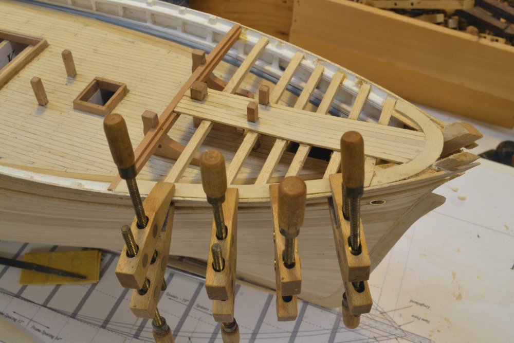
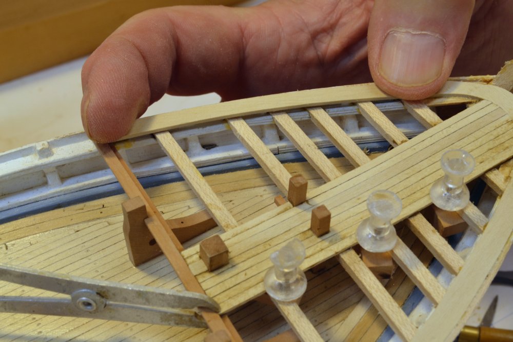
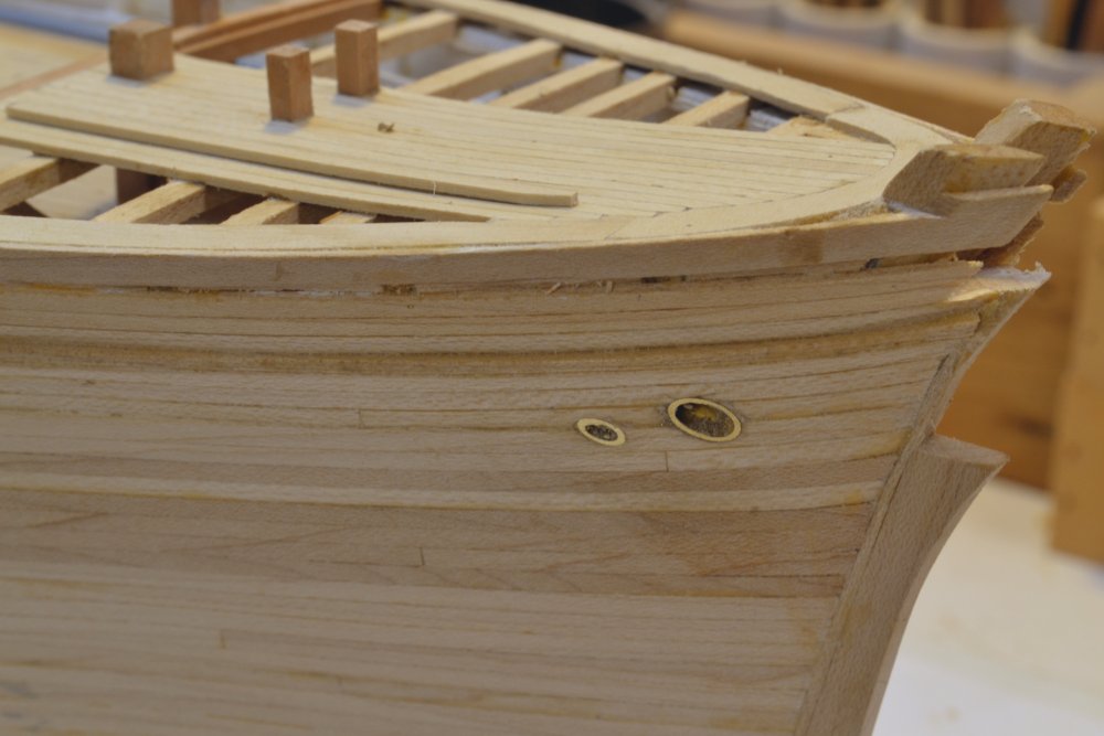
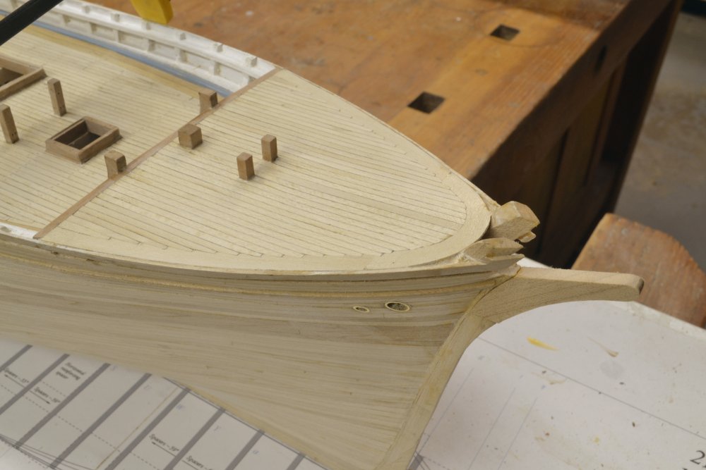
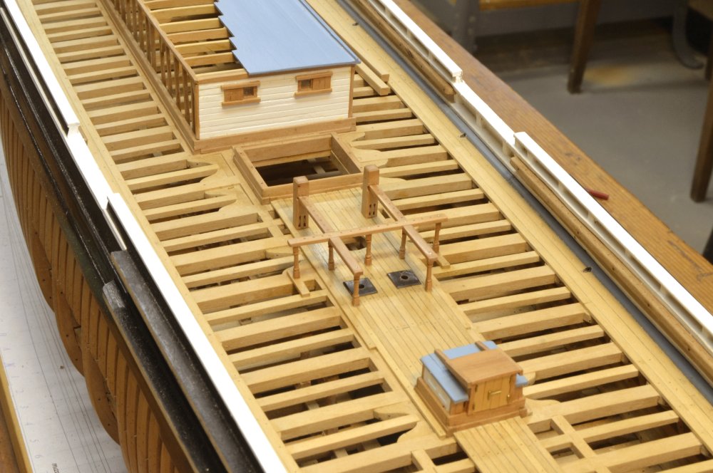
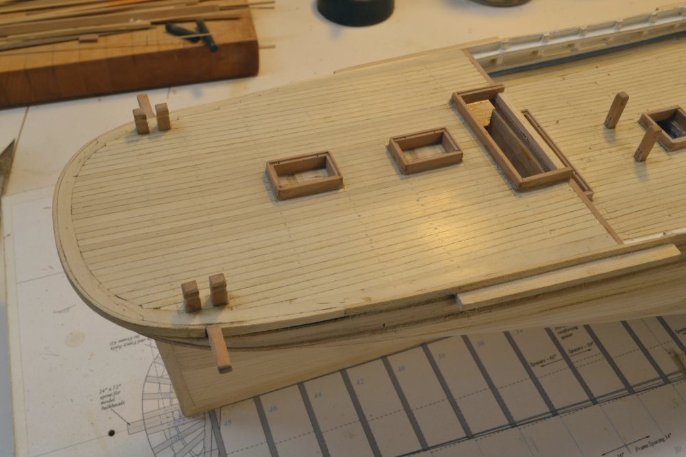
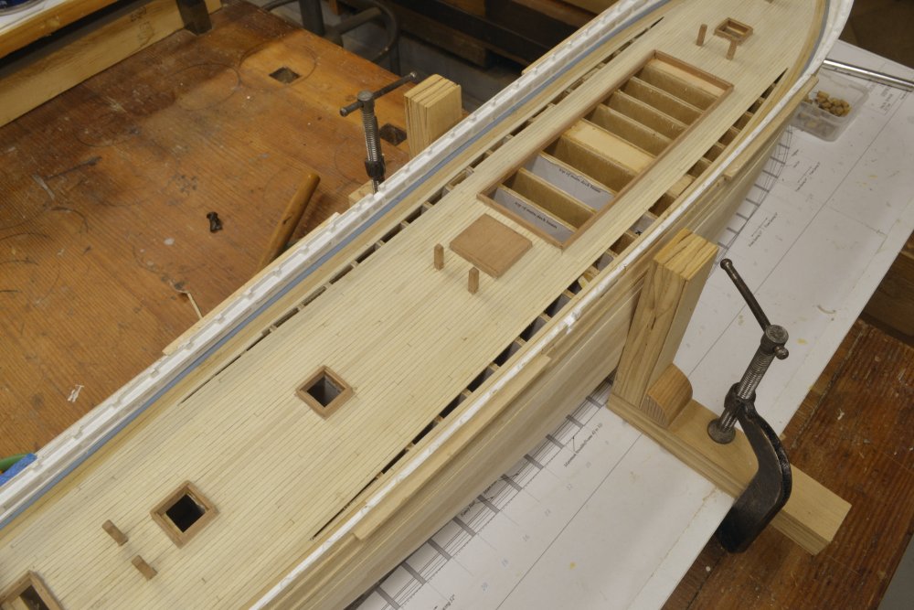
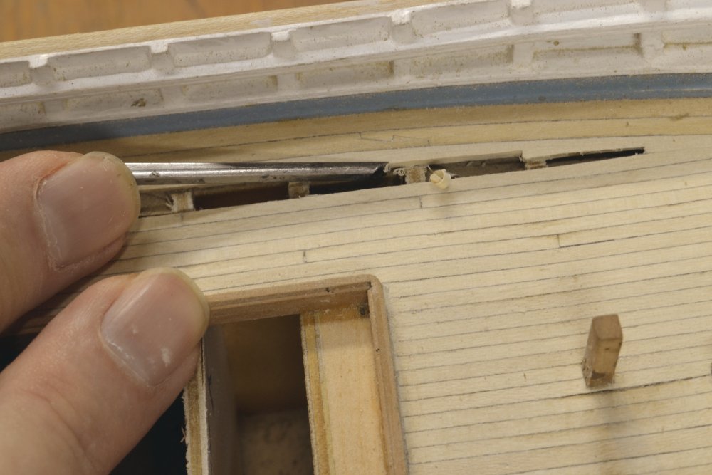
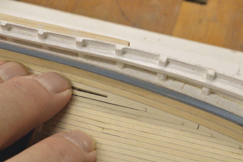
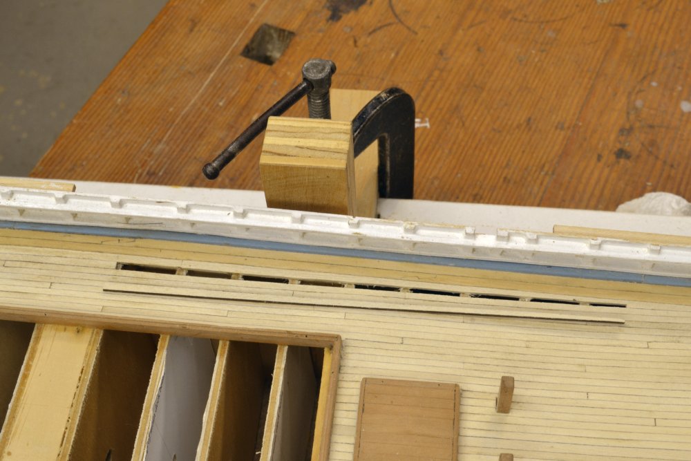
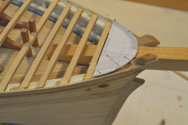
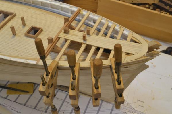
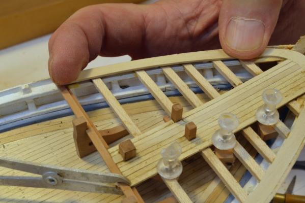
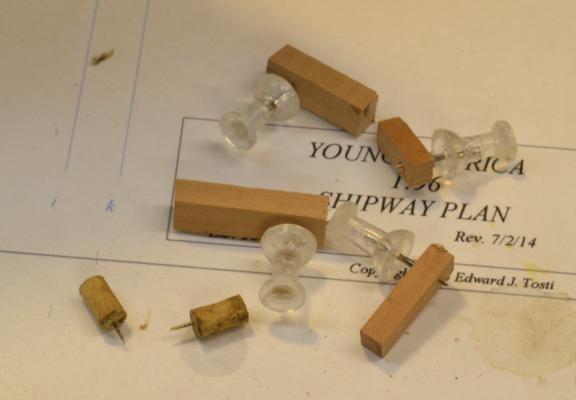
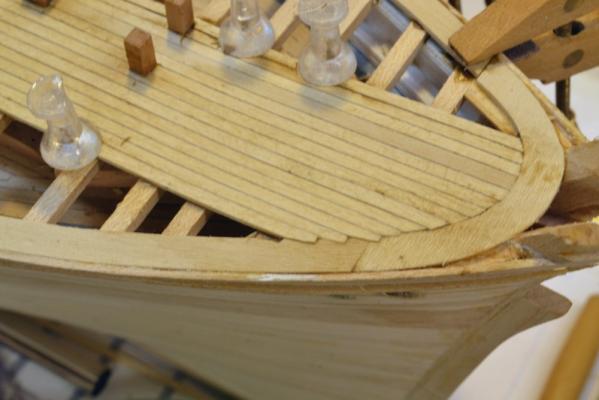
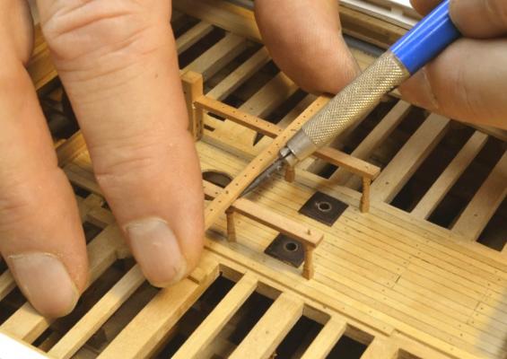
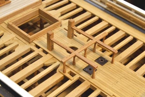
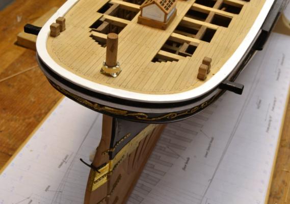
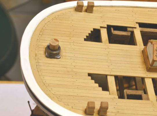
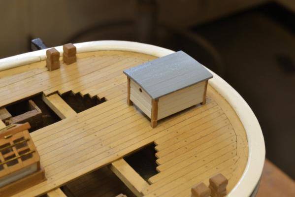
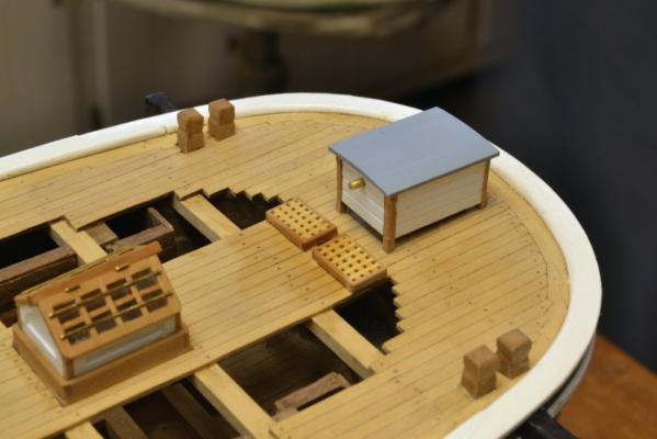
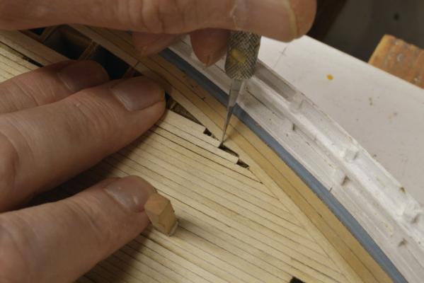
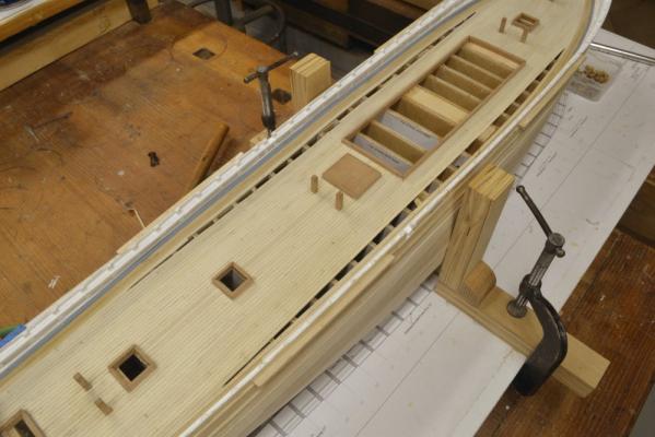
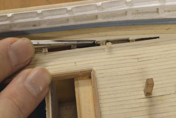
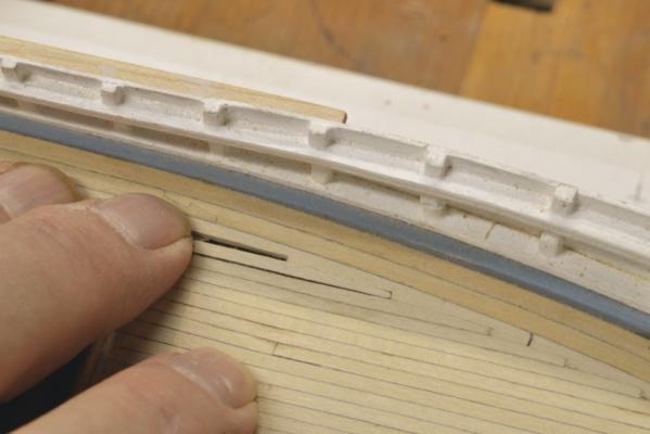
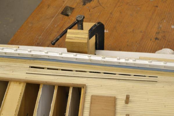
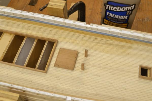
Young America 1853 – POB 1:96 Part 37 – Forecastle Deck Beams 3 In the first picture, all the forecastle beams have been installed and a template has been used to cut the outside line of the margin plank at the bow. A dummy bowsprit has been inserted to assure the final fit. The beams have been set down into the main rail so the deck planking at the side will be flush with the tops of the outboard planks. As mentioned earlier, there was no attempt to create authentic framing for this since all will be hidden by the deck. Note also that the mooring bitts have been installed. Square holes were cut into the main deck planking to insert these and glue them to a pine supporting member beneath. They are mortised to fit over the forecastle deck beam. In the next picture the margin plank has been installed at the bow and the starboard section is being glued to the beams. Deck planking was started at the center as with the main deck. In the next picture the port margin plank is being fitted. Planking continued concurrently with the margin plank work. Clamping required some thought. To keep the appearance of this deck consistent with the other decks, I did not want to drill the planks for pins as was done on the framed model, but the method used for the other planking on this model (pin clamps) could not be used on the light, hardwood beams. The clamps used in the picture were made using drawing pins. These are shown in the next picture. The pin clamps that could not be used on this decking are shown at the lower left. The drawing pin screw clamps were made by cutting crude threads on the drawing pins with a jewelers die plate, then screwing them into holes in pear blocks as shown. The blocks could then be slipped under the beams and the pins tightened over the glued planks. The next picture shows some of this work. In this picture the ends of the planks were joggled into the margin plank after the angle of the butted ends reached about 60 degrees. To be correct, the margin plank joint shown in this picture could have been made as a hook scarph. Most of it will be covered by the capping fancy rail. The next picture shows the decking flush with the top of the side and also the finished hawse holes and linings. Note that the outboard part of the main rail is still missing and was not added until after painting. The last picture shows the completed forecastle deck. The billet under the bowsprit has also been installed. The triangular spaces between the margin plank and the knightheads would be covered by the capping rail later. This was the state of the model at the end of August. Next, the channels and pin rails. Ed


- 191 replies
-
- 27
-

-
- young america
- clipper
- (and 1 more)
-
Thanks again, everyone. I appreciate the comments and likes - and best of all questions. Frank, I could well have used epoxy. The CA penetrates better to hold the wire "bolts" in the wood. It was also easier - and also, considering that my aging epoxy has turned into a solid mass .... Ed
- 3,618 replies
-
- 7
-
-
- young america
- clipper
- (and 1 more)
-
Lovely work on the wheel, Ian. Sorry, I can't help much on the binnacle. Ed
-
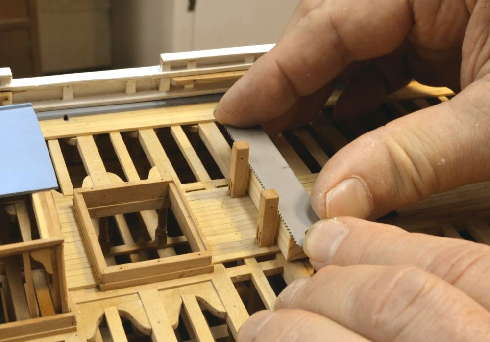
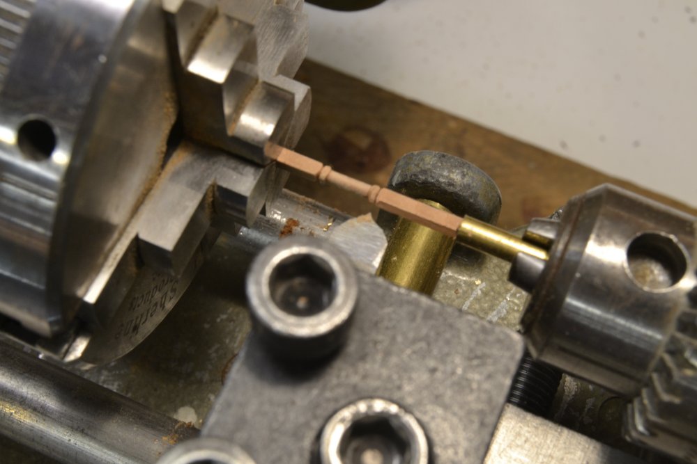
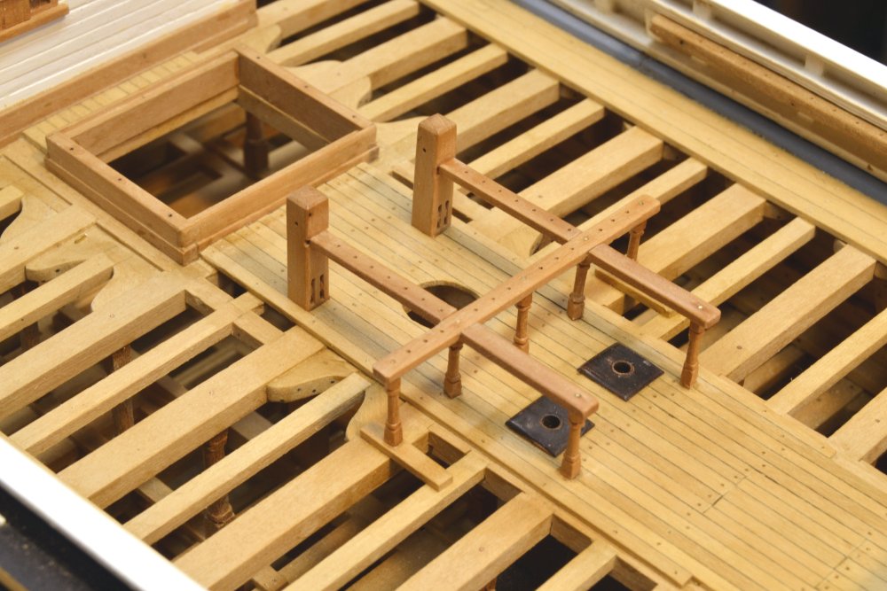
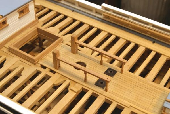
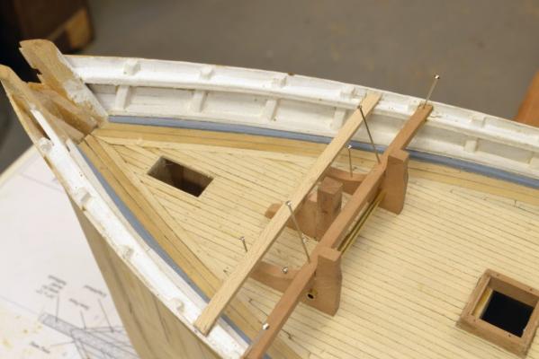
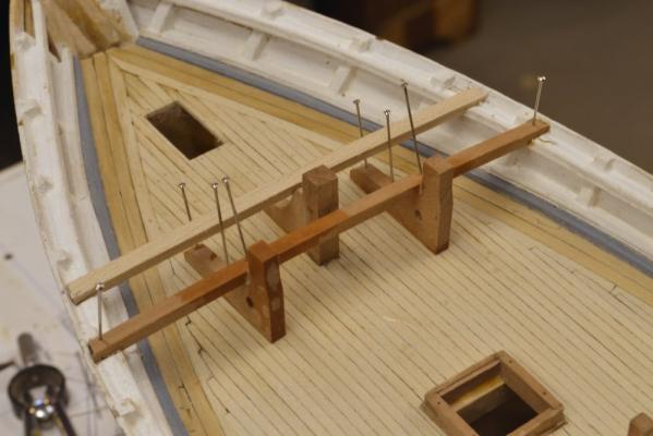
Young America - extreme clipper 1853 Part 127 – Main Fife Rail The completed main fife is shown in the first picture. It consists of two fore and aft rails, joined by a long athwartship rail. All are supported on turned pillars and are drilled for belaying pins. The ends of the fore and aft rails are set in slots in the topsail sheet bitts and secured with wire bolts. The pillars also are secured top and bottom with wire bolts. The fore and aft extensions aft will eventually support the bearings for the bilge pump. When making and fitting the sheet bitts, I neglected to cut the slots for the rails, so these had to be cut in place. I would normally do this with the serrated edge of a flat file, but none that I had would fit between the bulwarks, so I used a piece of hacksaw blade, sharpened up a bit to cut cleanly. This is shown in the next picture. The blade is supported on a sized pine block to ensure parallel cuts at the correct height. It was also rounded to match the deck, and although not shown in this picture, it was fitted with a stop block between the bitts to keep it in place. It would have been much easier to do this before setting the bitts, but doing it this way I can at least be assured that the rails will be at the same height. In the next picture, one of the rails is being test fitted on one of the pillars. The block used to guide the saw also proved useful in sizing the pillars. The pillars were turned by the method used on the deck beam pillars – shown in an earlier post. In the next picture, one of these has been turned and awaits final sanding/polishing. The pillar is held on center by a brass tube in the tailstock chuck and the depth of cut is controlled by the larger brass tube fitted over the cross feed rail below the tool. The next picture shows the two fore and aft rails fitted temporarily. In the next picture the athwartship rail is set down on its wire bolts and the rails below are being marked for the lap joints that join the rails. The rails were then removed to cut the joints. In the last picture the completed assembly has been installed and polished. The rail assembly was glued down and to the bitts using medium viscosity CA. I was not confident that all these endgrain joints would stand the pressures of rigging using wood glue. The structure is quite strong. Ed


- 3,618 replies
-
- 43
-
-
- young america
- clipper
- (and 1 more)
-
I suppose the best way is to post on the book topic, but I do not mind either way. More people may see it here, but on the other hand if readers of the book get in the habit of keeping up with the book topic, I can use that not only for corrections but for other supplementary information as well. The book topics are a bit buried in the website, however, so I am of mixed mind on this. I will definitely post all Addenda on the book topic, but will also respond here. Either way, I appreciate your pointing these out. I hope there will not be very many of these. However, with several hundred complex drawings between the full sized prints and the CD - and only me to review and correct them as the build proceeds - there will be some. I will make every effort to make and post corrections to these as soon as they are detected - by me or readers. As a matter of interest and for some insight into the issue, I am currently working on the windlass - a complex piece of machinery with a number of small machined brass and wood parts. The windlass construction is shown on a single letter-sized drawing, one of many that will go on the Volume II CD. This drawing has been revised 7 times so far as the work proceeds and is due for at least a few more changes to reach its final state - at which point it should be usable by readers. I normally make sure the drawings reflect the as-built model and also the learnings from the process - not always perfectly for sure. So, thanks again. Ed
- 3,618 replies
-
- 12
-
-
- young america
- clipper
- (and 1 more)
-
Giampiero, Thanks for your comments - and thanks to all those who checked the "like" box. I assume the saw your are referring to is the small Preac circular saw shown ripping a beam in post 35. This is truly a great little tool. I like it because it is simple, very solid in its construction and is a perfect size (2 1/4" dia. blade) for small work. It lacks a tilting arbor, but this helps keep the blade rigid. Adjusting the blade height is also a bit awkward. However, the saw never needs any adjustment and always makes perfect cuts. I purchased the saw many years ago from Preac. It is no longer available - except perhaps on ebay, but not currently. The business closed when the owner passed away several years ago. Ed
- 191 replies
-
- 5
-
-
- young america
- clipper
- (and 1 more)
-
Thank you again, Bob. The stern assembly template is, of course, correct, since it shows the relationship to other members. Attached you will find a corrected 1 to 72 Stern-Deadwood Patterns Sheet. 1to72 Sternpost-Deadwood Patterns.pdf Thanks, again, for picking this up. I will post an addendum on the book topic. Ed
- 3,618 replies
-
- 5
-
-
- young america
- clipper
- (and 1 more)
-
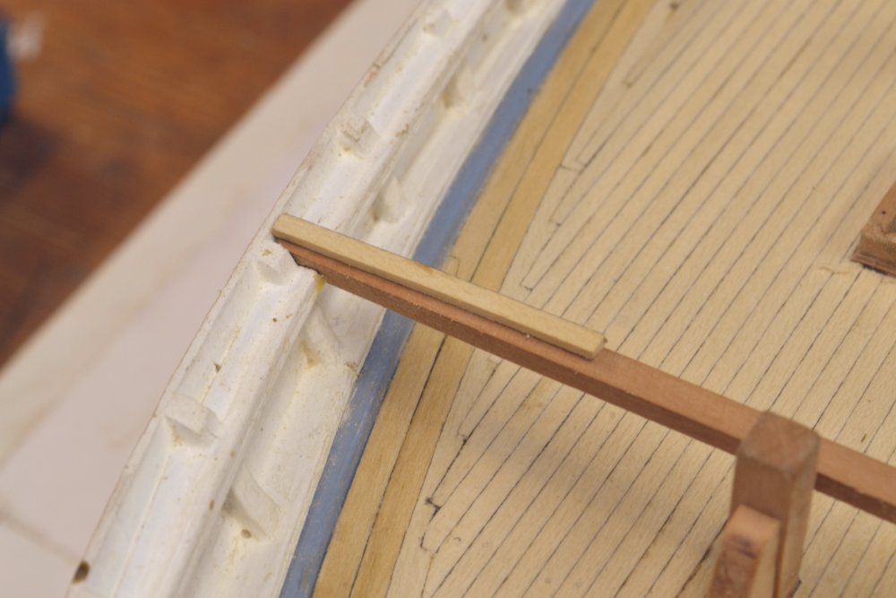
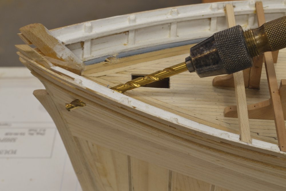
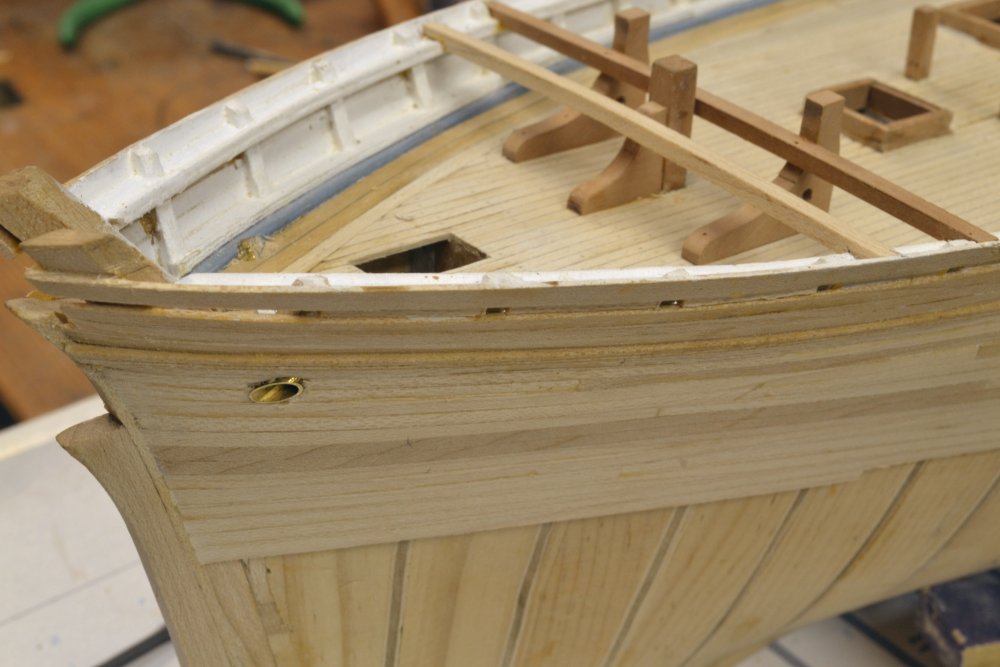
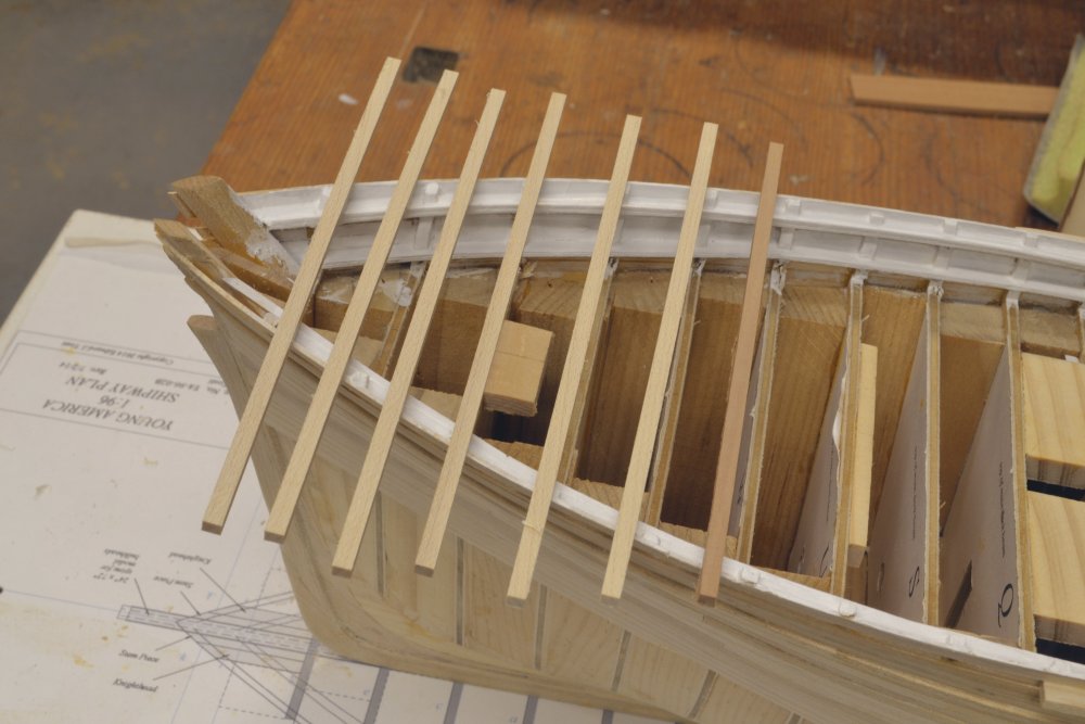
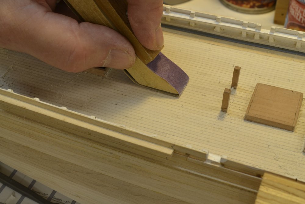
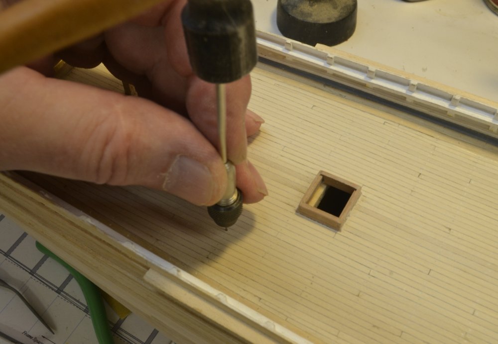
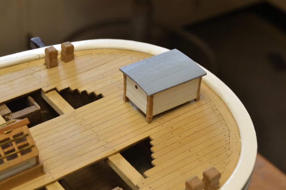
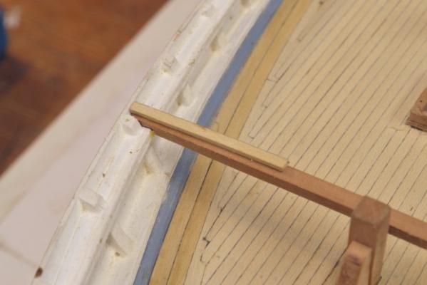
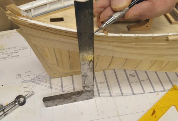
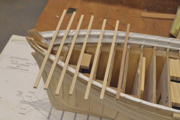
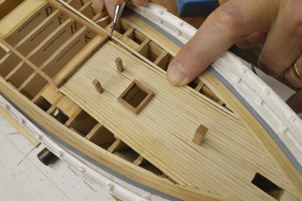
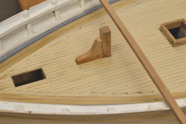
Young America 1853 – POB 1:96 Part 36 – Forecastle Deck Beams 2 Before setting the forecastle deck beams some under-deck work had to be completed. In the first picture the main decking under the forecastle has been completed, the opening for the bowsprit has been sized and a large knee has been fitted to the forward side of the Samson post. On this model the bowsprit will step on the plywood bulkhead at the aft side of the opening. A dowel into holes in both the bowsprit and the bulkhead would probably be the simplest method. Next, the carrick bits that will support the windlass shaft were cut out. In the next picture, blanks for two bits were pasted together with one pattern and are about to be cut out on the scroll saw. These two bits needed to be identical and also carefully fit so the windlass will be horizontal and will clear the deck and breast beam. I left the bottom edge with some excess so the bits could be tailored to fit the actual space with the correct height above the deck for the holes that will take the windlass axle. These bits also provide central support for the forecastle breast beam, so that beam needed to be positioned before fitting the bits. In the next picture that beam has been cut to length and its height is being set at the side using a strip of deck plank. The deck planking needs to be flush with the top of the side. The height along the top of the side was well checked much earlier. I set the deck beams on the top of the main rail, since this is at a convenient height. Either the beam could be cut back or the rail notched to get the beams at the correct height. All of this structure will be hidden by the deck, so any deck knees can be ignored. Unlike all the main and lower deck beams, the forecastle deck beams are not set on the frame lines. To mark the beam locations, measurements were taken from frame lines on the plan drawing for the forecastle and transferred to the shipway plan using dividers. In the next picture a deck beam location is being transferred from the plan up to the rail using a square. The line drawn at the beam location can be seen at the base of the square. With the first two beams positioned, the carrick bits and the Samson post knee could be trimmed to provide support for the beams. All these parts have been fitted in the next picture. In this picture the carrick bits are pinned in place. They have been positioned with a temporary windlass axle installed so they would be aligned when pinned. The height of this axle was set using a gauge block cut to the correct height when the bottoms of the carrick bits were trimmed before setting. In the next picture the axle has been removed and the bits glued to the deck. In this picture the breast beam has also been glued at the rails and to the carrick bits. All pins were later replaced with copper wire bolts. Before going any further the hawse holes needed to be drilled out and lined. In the next picture the main hole on the port side is being drilled to final size by hand using a pin vise to hold the drill. Small pilot holes were drilled first by eye after locating the inside and outside centers – before enlarging the holes to final size. The locating method was described in one of the posts on the framed model and in detail in the book. It is basically a matter of locating the fore and aft positions and the heights on the sheer plan and transferring those to the hull using a height gauge. The centers at the inside are at the waterway where intersected by keel-parallel lines from the centers of the chain tubes. The last picture shows the brass lining inserted into the sized hole. All four hawse holes were installed in this manner. The linings were the filed off flush on the outside. Work on the forecastle deck will continue in the next part. Ed


- 191 replies
-
- 33
-
-
- young america
- clipper
- (and 1 more)
-
Beautiful work on the wheel and capstan, Ian. I like the descriptions of your methods and the tooling you have devised to do the work. Great stuff. Ed
-
Fine work, Nils. I look forward to seeing all the topside detail. Ed
- 2,625 replies
-
- 5
-
-
- kaiser wilhelm der grosse
- passenger steamer
- (and 1 more)
-
Mark, I am sure what you suggest would work fine. It would act as a guide that would keep the beams from twisting. The only disadvantage I can see is that it would use the same line of sandpaper - unless it was made to adjust side to side. Ed
- 191 replies
-
- 4
-
-
- young america
- clipper
- (and 1 more)
-
Thanks for the "likes" and... thank you, Greg. See Naiad Vol II or YA Vol I for the complete method. Its best to thickness sand the beams before slicing them off - as decscribed. Individual beams may twist when passing through the sander. It does work like a charm producing uniform beams and saves many hours. Ed
- 191 replies
-
- 5
-
-
- young america
- clipper
- (and 1 more)
-
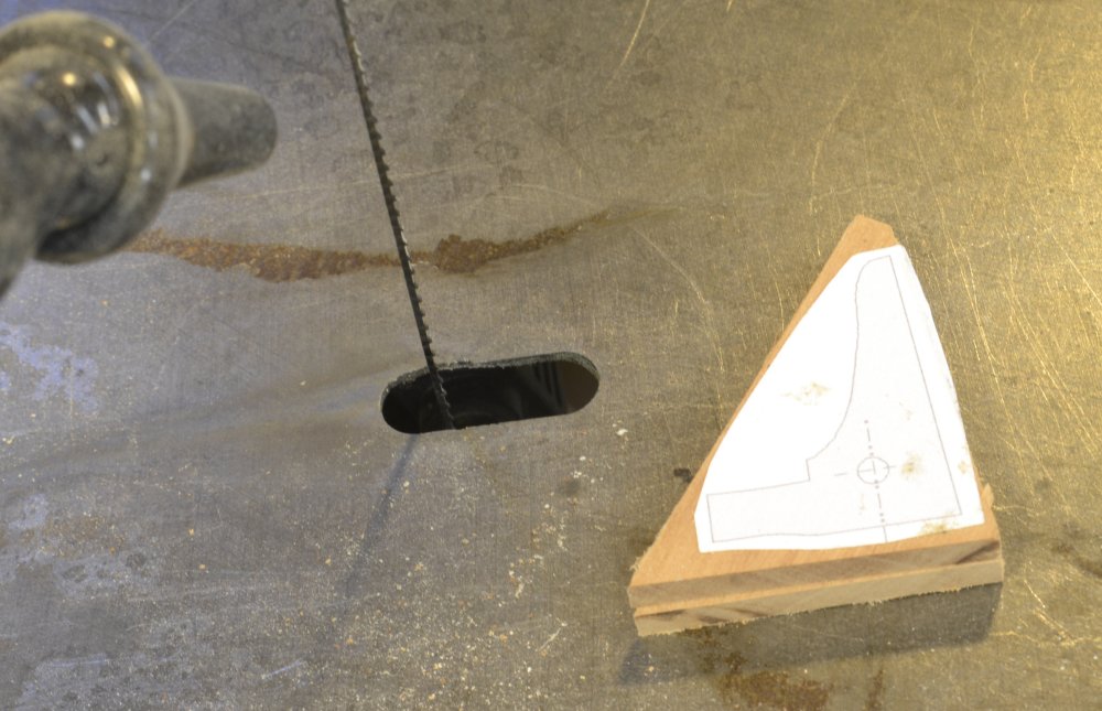
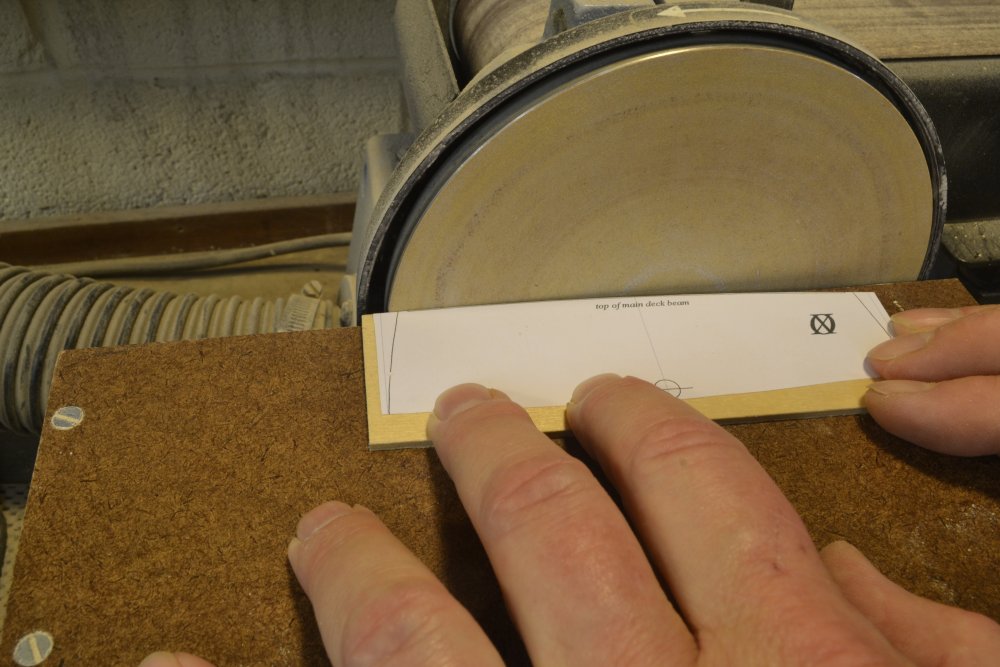
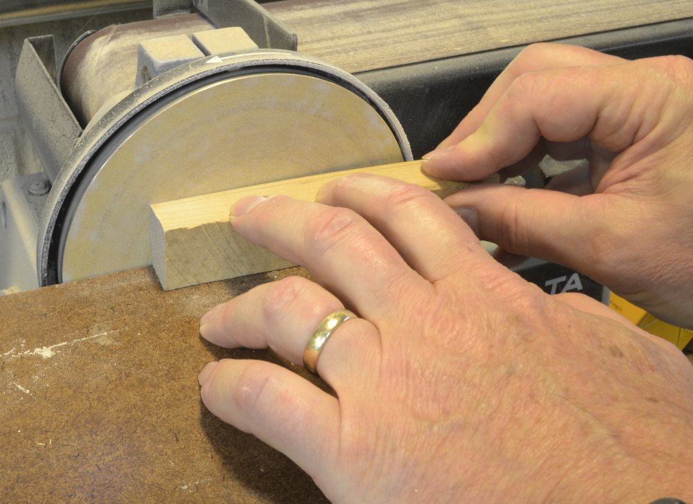
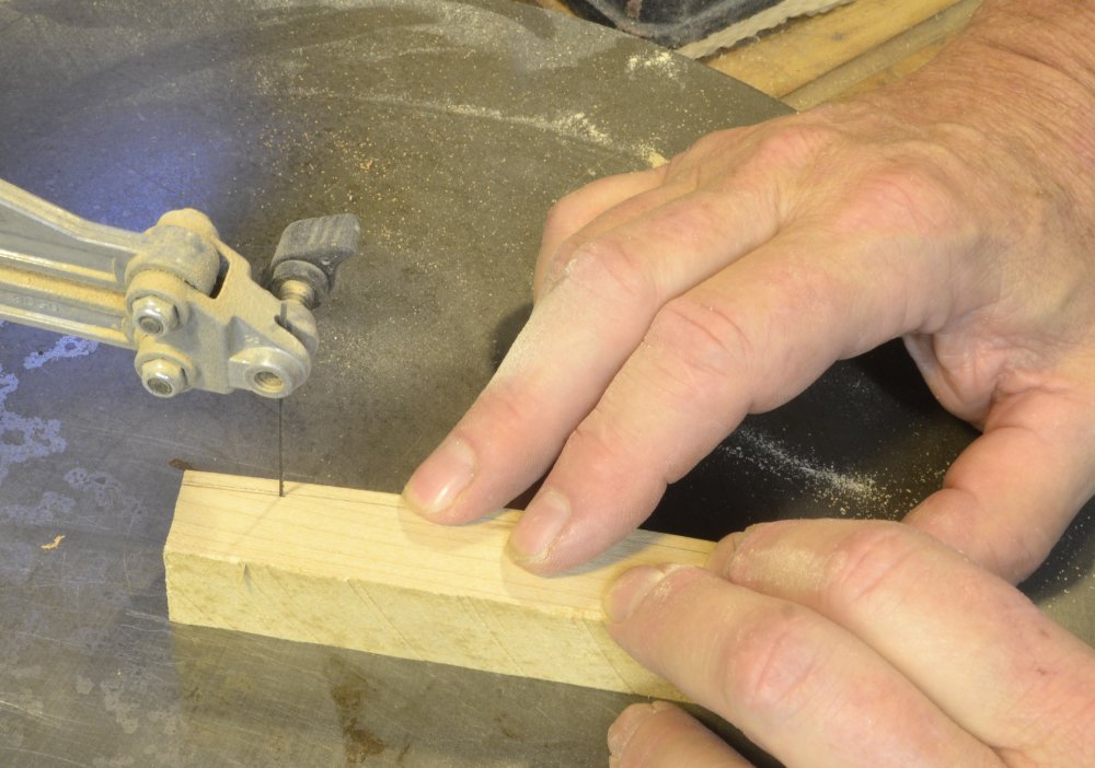
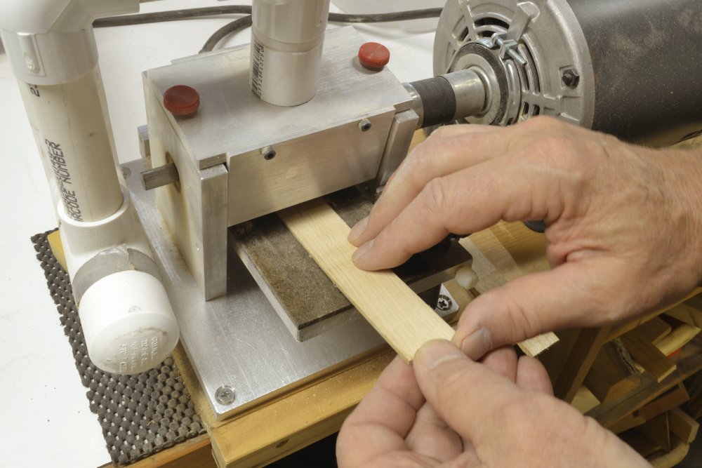
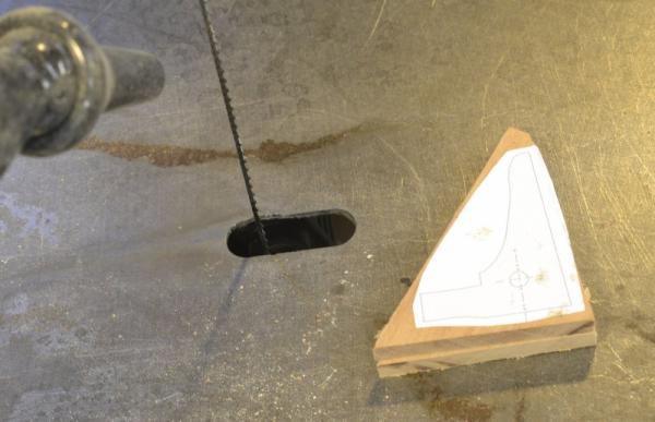
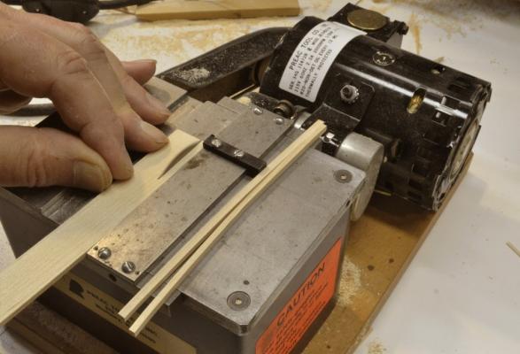
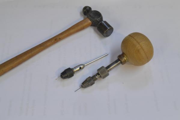
Young America 1853 – POB 1:96 Part 35 – Forecastle Deck Beams The POB model has some real deck beams to install – not many – just enough to introduce the method used on the framed model to POB builders. The method I used to make the forecastle beams – as well as the breast beam at the poop shown earlier – was very similar to that used on the framed model, but somewhat simpler. It begins with a template for the round up of the beams. In the first picture, a copy of one of the bulkhead patterns has been pasted to plywood and the curve of the deck is being sanded on the edge. Since the round up radius is the same for every frame and every deck, any one of the patterns could be used. The template was then used to trace the round up on to a piece of maple. The curve was then sanded on to this piece as shown below. Using a compass the depth of the forecastle beams was then drawn along the curve. A blank that will be sliced into several beams was then cut off along this line, allowing some excess for sanding. I then used the thickness sander to impart the final thickness on the underside of the beams as shown in the next picture. The thickness sander does a great job with this. The depth is uniform and parallel to the top face. It is also very fast. Without a thickness sander, I would have cut very close the line with the scroll saw, then sanded the underside by hand – not too arduous a task. The individual beams were then ripped off –top side down! – on the circular saw as shown in the next picture. The last picture shows the six maple beams and the breast beam, for which pear was used since it will be exposed and not painted. As can be seen, I made these beams long before they were needed - before the planking of the main deck. Cutting and fitting of the beams will be described in the next part. Ed


- 191 replies
-
- 35
-
-
- young america
- clipper
- (and 1 more)
-
Thanks for all the good comments. I would add that in addition to a sharp tool and very lights cuts - slow advance of the tool - it is also essential to have the parting tool relieved - narrowed - behind the cutting face so the sides do not rub as the cutter advances - in this case on the parted rim. As far as tool recommendations, I cannot draw comparisons. I have a very old (1978) Unimat SL Lathe (long discontinued) with a lot of accessories that I hope will outlast me. If it does not, I would buy a Sherline. I have a Sherline mill that I find to be a very good tool - very rugged for its size, very precise, full line of good accessories. An easier to use - screw tightened - milling vise would be welcomed. Also, there is a great advantage in having one brand, in that accessories are expensive and cross compatibility between the lathe and mill is most useful. Ed
- 3,618 replies
-
- 12
-
-
- young america
- clipper
- (and 1 more)
-
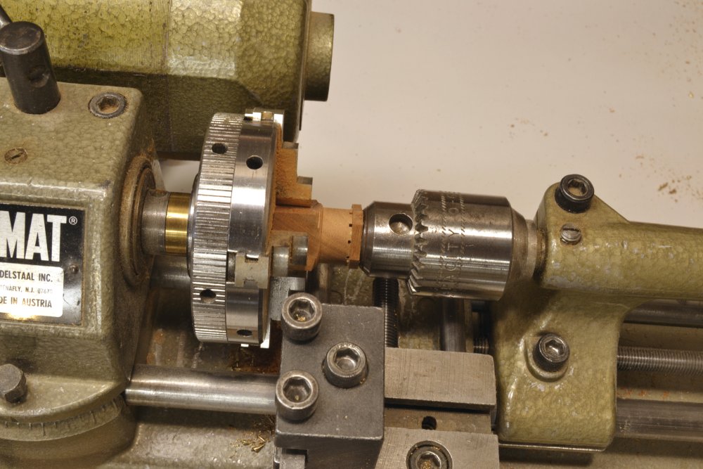
Thanks for the comments and all the likes. To answer your questions Harvey: The tool to remove the area between the rim and the hub was a small, square-ended, relieved parting-off bit with the underside ground back to clear the rim - a pretty fragile tool. I did not take any photos of this. However, here is a photo of this step on a European boxwood, double wheel I made for Naiad. On this double wheel I drilled holes for spokes after turning the rims/hub. I did not use this wheel because I decided to make square, turned spokes instead, so the slots for those would have been cut before this step - as was done for the single YA wheel. The Naiad wheels were much more complex - two rims, pentagonal offset segments laminated for the rims, precise spacing between the rims, milling of slots between laminating steps, spokes spaced correctly between the segment joints, etc. However, the picture does show the tool used - in this case the depth of cut had to reach through both rims. I am not sure what you mean in your next question about the rim moving around on the spokes. The centering of the rim is well held in place even without gluing the spokes. With all the spokes inserted there is no direction that it can move. However, the spokes are not strong enough to take the stress of turning the rim, but they do not have to, because until the rim is parted all the cutting stress is taken by the connection to the main block - until the rim is cut through. No turning of the rim is advised after parting through the rim. The spokes only go through to the center hole - not all the way through. Even with the rotary table - or the indexing head I used for Naiad - and the precision of the mill, it is very difficult to get good hole alignment with very small drills needed for smaller scales. They wander. Ed
- 3,618 replies
-
- 16
-
-
- young america
- clipper
- (and 1 more)
-
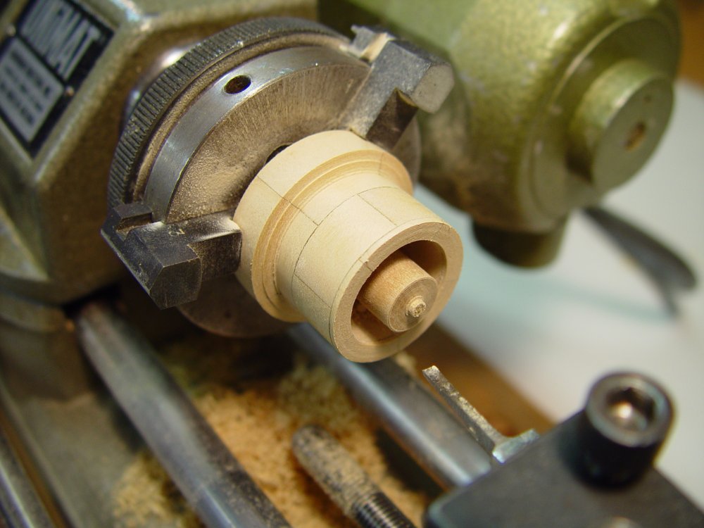
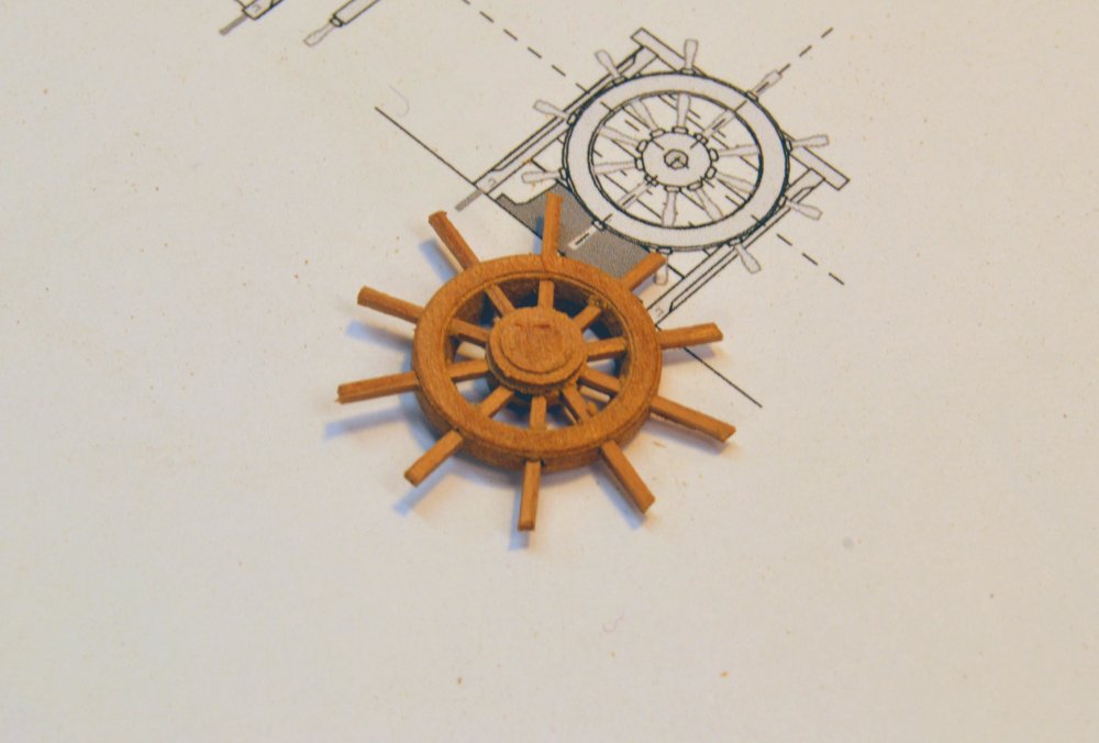
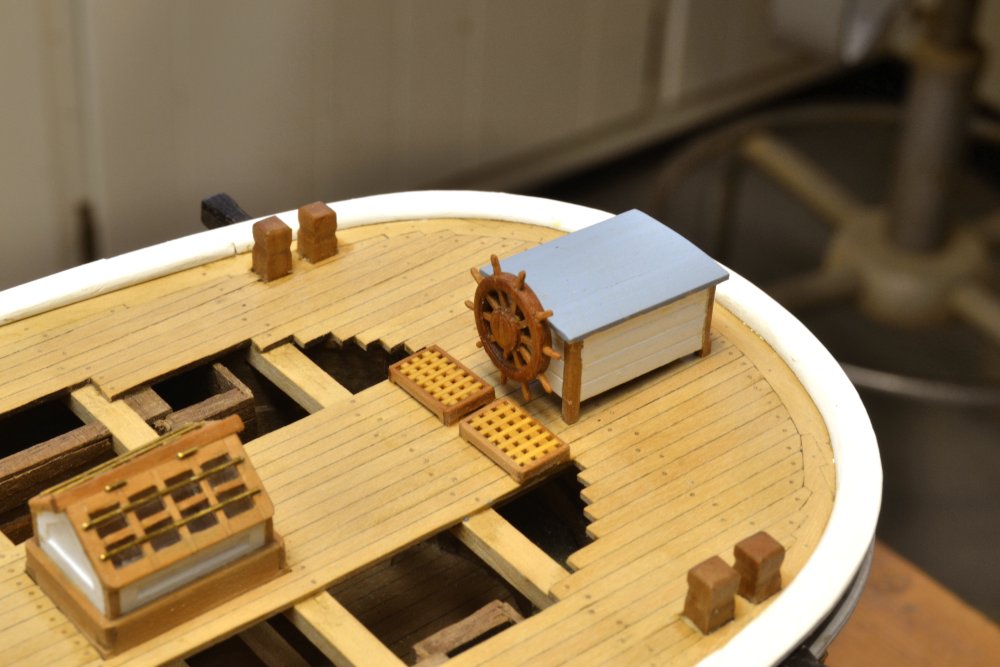
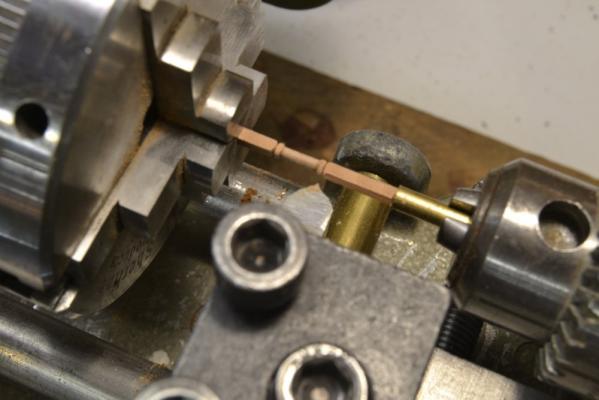
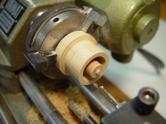
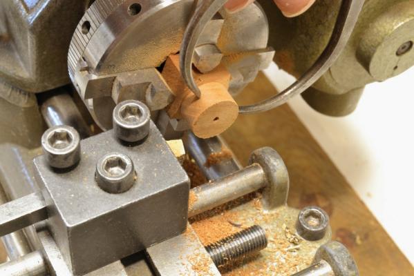
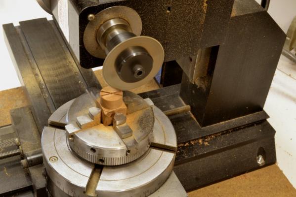
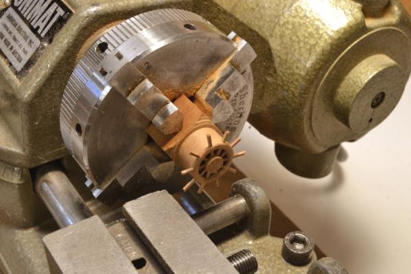
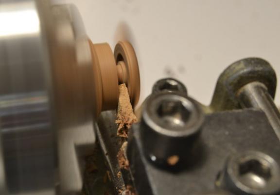
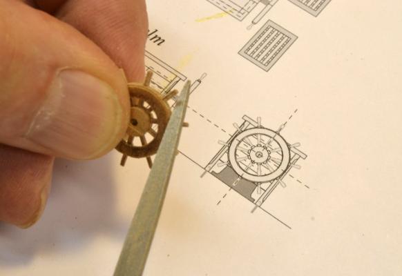
Young America - extreme clipper 1853 Part 126 – The Wheel I had hoped to make the wheel by the same methods used for the larger wheels on Naiad, but do to the smaller size of this wheel and the material, I found that some compromises would be necessary. They are described later, below. I wanted to use a darker wood for the wheel and decided to use cherry. This is less hard and strong than the European Boxwood I used on the Naiad wheel. In the first picture the outer diameter of the wheel has been turned in the lathe and the 39” (.54” act.) diameter is being checked. The square cherry block in the four-jawed, self-centering chuck has its grain running perpendicular to the centerline of the lathe. This would permit using a cross-grain lamination to strengthen the final assembly. The 1/16” hole in the center of the turning was centered carefully using a center drill in the tailstock, before boring the final hole that will eventually receive the wheel axle. In the next picture, slots for the 10 spokes are being milled in the face of the turning. For this work the chuck was removed from the lathe to the rotating table on the mill without removing the turned piece. The saw was then centered on the turning and brought down into contact with the face. The blade here is .032” thick and it was lowered into the work to make a slot about 2.5” inches square. After each cut across the face of the piece, the table was rotated 36 degrees and repeated to make all the cuts for the 10 square spokes. In the next picture the piece has been returned to the lathe and a laminating piece is being glued on with the grain at 90 degrees to that of the turned piece. The drill chuck in the tailstock is being used to clamp the glue joint. This single cross grain lamination is already a much simpler construction than the multi-layer pentagonal assembly of the two Naiad wheels. After the glue had dried the added piece was turned to the rim diameter and its entire face trimmed off to the final thickness. The next step was to remove the area between the rim and the hub. This leaves an integral rim/hub turning that will ensure centering of the hub. The 10 square spokes were then slipped into the piece as shown in the next picture. I had intended to insert these temporarily, to be replaced with the final turned spokes later – one-by-one as was done on the Naiad wheels. However, I decided this would be impractical on this small wheel. Apart from the difficulty expected in turning these very small cherry spindles, the amount of gluing surface at the hub was too small without the spokes. For these reasons I decided to glue these square spokes in at the hub and round the handles by hand. The next picture shows the inside face of the rim being turned through to the hub. Once the cut passed through the ID of the rim, only the spokes held the assembly together – as with the real wheel.. In the next picture the wheel has been parted off and is ready for final sizing and shaping of the handles. The next picture shows the handles being shaped using diamond grit files – very carefully, since the glued-in spokes may not be replaced if one is broken, The last picture shows the finished wheel mounted on the helm enclosure. The enclosure is still removable and I expect it will spend the next many months stored away somewhere, safe from damage during the remaining construction and rigging of the model. Ed


- 3,618 replies
-
- 38
-
-
- young america
- clipper
- (and 1 more)
-
Addendum 1 - correction There is an error on the 1:72 Stem Patterns that was included on the CD in the subfolder for Chapter 3. All parts of the apron should be sided 16” not wider at the head as incorrectly noted on the pattern sheet. This pdf should be replaced with the attached, corrected version. The text on p.33 is correct. 1to72 Stem Patterns.pdf Sorry for any inconvenience. Ed
-
Hello, Bob. You are correct. "Sided" or "siding" refers the the dimension "contrary" to the molded, that is to the curved edge(s) on the piece. In the case of the apron this is the athwartship dimension. I believe the drawing note you are referring to is on the stem pattern sheet and reads something like "apron sided 35" the head and 16" at the foot." This note is incorrect. The apron is sided 16" over its entire length, as indicated in the text on p. 33. I will review the drawing and post a corrected copy of the pattern sheet in the YA book topic section. Thanks for pointing this out. Ed.
- 3,618 replies
-
- 3
-
-
- young america
- clipper
- (and 1 more)
-
Laman, Finishes are heavily influenced by personal preference, so there is never a "right" answer. The best approach is to test finishes on scrap model wood to see what you like and get familiar with them. Perhaps a brain dump of what I think about will be helpful, or at least give you some ideas to pursue: On bare, natural wood on framed models, I prefer beeswax/turpentine for a number of reasons. In appearance, it leaves the wood in a natural state - not film covered. It is easy to apply and can be done piecemeal without fear of overlaps showing differently - because it is self dissolving with each added coat. I like the penetration vs. a surface finish like varnish or sealer - unless a definite gloss is desired. The turpentine/wax solution penetrates the wood, leaving the wax in the wood as the solvent evaporates. So the finish has more depth. I think this gives a richer look. Adding more coats of wax then buffing will add sheen. Excess wax (or sheen) is easy to remove by buffing or wiping with turps. Beeswax imparts some warming of the color (yellowing), but much less than oils like linseed or Tung, which can leave some woods, like pear, appearing orange. Oils also build gloss with each coat and do not self dissolve, so progressive finishing (like working up from the lower framing) may leave glossy areas at overlaps. Oil finishes also have a habit of later oozing out of corners, joint crevices, and pores and then polymerizing on the surface - leaving glossy spots that are very hard to remove. Water based sealers and varnishes(acrylic) do not yellow even with aging, nor does microcrystalline wax, which could be used like beeswax - with a solvent. Sealers and varnishes penetrate very little, leaving a film on the wood. This is good if you want an easy gloss, which is why I tried it on the POB decking. Oil based varnishes or shellac also lay on the surface and can be polished to a gloss. These yellow the wood and darken with time - like oils Solvent based varnishes are oils, but with driers added. Some of the above relates to technical performance but much is preference. Ed
- 191 replies
-
- 12
-
-
- young america
- clipper
- (and 1 more)
-
Thank you, E&T, John and others for the likes. John, I am sorry for the confusion. I did not use beeswax on this model, but used it without any other finish on unpainted wood on the 1:72 framed model. Only the applications of acrylic described in the post were used on the POB model deck. Ed
- 191 replies
-
- 3
-
-
- young america
- clipper
- (and 1 more)
-
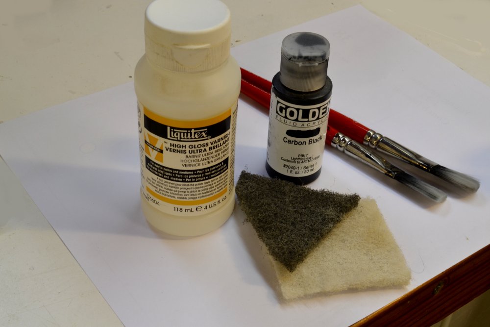
Young America 1853 – POB 1:96 Part 34 – Main Deck Finishing After all the deck planking was installed, it had to be leveled off and finished. Regardless of how well the plywood bulkheads and the added under-deck supports are faired off beforehand, it will be necessary to level off the planking using a combination of filing with flat rifflers and/or sanding with coarse (say 120-grit) paper. If you are building the model, I hope you will pay more attention to the bulkhead fairing work than I did. My fairing could have been a bit more thorough. The deck has some waviness, but only those permitted to touch it will notice. Regardless of the perfection of the bulkhead fairing, it will be prudent to start with heavier deck planks – say 4 ½” thick vs. the final 3 ½”. The first picture shows some 220-grit finish sanding being done after all the irregularities between planks were leveled out using a flat riffler. I used this model to experiment with deck finish. On the larger model, beeswax thinned with turpentine was used on all unpainted wood – after more extensive sanding and polishing. After sanding with 220-grit, I finished this decking with water based, acrylic sanding sealer thinned to about 50% with water – two coats, each sanded smooth – 220-grit then 320-grit. The planking was then coated with acrylic gloss artists’ varnish. Two coats, thinned, each sanded with 320-grit and then rubbed with Scotchbrite® grey then white grades. This left a silky satin finish on the deck. Simulated deck fastenings were embossed after the first coat of varnish. I used a piece of syringe tubing for this and felt that the varnished surface would better resist pulling out small plugs. Deck fastenings on these ships were normally iron spikes driven into counter-bored holes that were later filled with wood plugs that usually matched the decking. The next picture shows the embossing in progress. For this work a length of syringe was held in a pin vise that could then be lightly tapped with a hammer. I was very careful to emboss all fastenings directly over bulkheads or other under-deck supports to avoid the possibility of breaking the planks. I used a light pencil line across the deck for each row, then alternated fastenings on either side of the line. The next picture shows the tools used for this. The syringe tubing had an OD of about 1 ½” and a sharp bevel was stoned around its end. I used a scriber point to flare out the end slightly to avoid plugs being jammed in and pulled out. The second pin vise shown was fitted with a small drill to use for cleaning out the end of the syringe as it became fouled. After this embossing work, the deck was sanded with 320-grit paper and rubbed out with Scotchbrite® in preparation for the final varnish coat. This was then applied, left to dry, sanded with 320-grit, and finally rubbed out with grey then white grades of Scotchbrite®. This left a polished sheen on the deck as shown in the next picture. I felt that the acrylic varnish worked out quite well. It dried hard enough to be rubbed out and polished to the sheen I was looking for. Below is a picture of some of the finishing materials and brushes used on the model. The finish used on the decks was Liquitex® High Gloss Varnish applied with the flat synthetic brushes shown. High gloss finishes contain no flatting agents so they can be rubbed out to the desired sheen without being limited by the dulling agents used in semi-gloss or matte finishes. The Scotchbrite® pads mentioned above were used for this and are shown in the picture. The black Golden Fluid Acrylic® shown in the picture was used on the hull finish – to be described later. Ed


- 191 replies
-
- 36
-
-
- young america
- clipper
- (and 1 more)
-
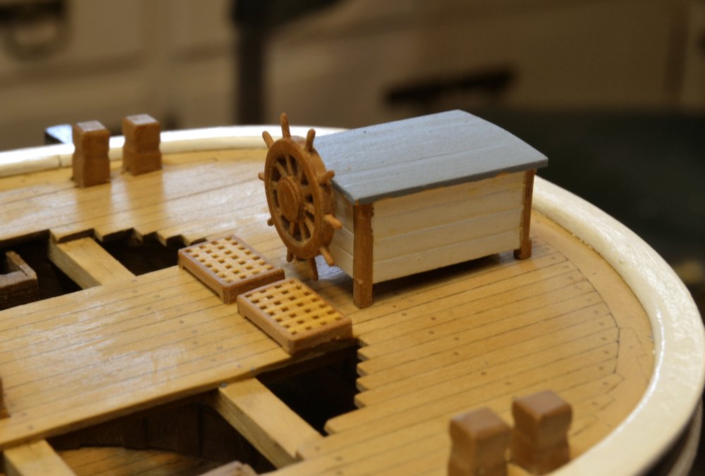
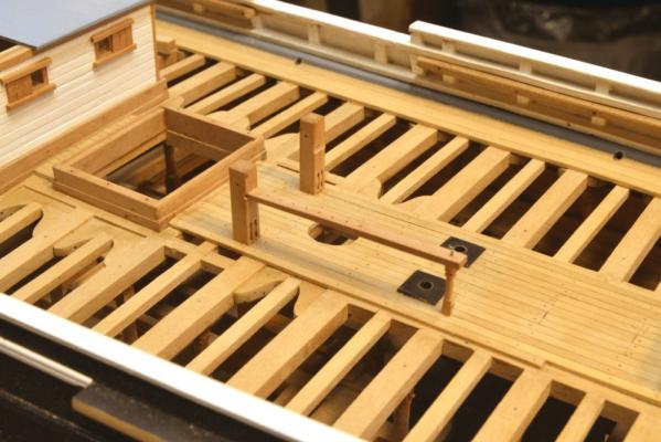
Young America - extreme clipper 1853 Part 125 – Helm First, thank you, Bob. Gross exaggeration, of course, but much appreciated nonetheless. The term helm refers to all the equipment and structures associated with the rudder. Unlike earlier ships where the wheel operated a tiller that turned the rudder by means of a system of ropes and sheaves, most ships of the clipper era used gear driven machinery to rotate the rudder. It is most likely that Young America used a mechanism consisting of reversed thread worm gears that drove a collar at the top of the rudder post. Gearing of this type had more mechanical advantage and resisted reverse forces generated by pressure on the rudder. Wheels could therefore be single and smaller even though the ships were larger and faster. Higher speeds put more stress on the rudder. I did not intend to model the rudder machinery, given the scale and the fact that it is enclosed from view. (The small wheel was enough of a challenge for me.) However, the lower part of the heavy machine base that supported the gearing would be visible because the rudder enclosure is open at the bottom. The first picture shows the rudder shaft and a brass turning that models the lower part of the cast iron machine base. In the next picture the rudder head has been shortened and the iron base blackened. The base was simply glued to the deck using medium viscosity CA. The next picture shows the completed helm enclosure waiting for the wheel. The enclosure is fixed temporarily to the deck on wire pins into the corner posts. This will allow the helm - with the fragile wheel - to be left off the model where it will be safe from damage as other work proceeds. In the next picture the wheel axle has been fitted into a solid block inside the enclosure and two small grated platforms have been installed to help keep the helmsman’s feet dry. The helm enclosure was made by the same methods used on the other deck structures so I will not describe that here. The last picture shows the completed helm with the wheel fitted. I was fortunate to be able to use some grating left over from the 1:96 Victory model – just enough for the two raised platforms. I will cover making the wheel in the next part. Ed

- 3,618 replies
-
- 43
-
-
- young america
- clipper
- (and 1 more)
-
Close up photos are our most severe critics, Nils - and they are far too critical, I fear. Lovely work. Ed
- 2,625 replies
-
- 6
-
-
- kaiser wilhelm der grosse
- passenger steamer
- (and 1 more)
-
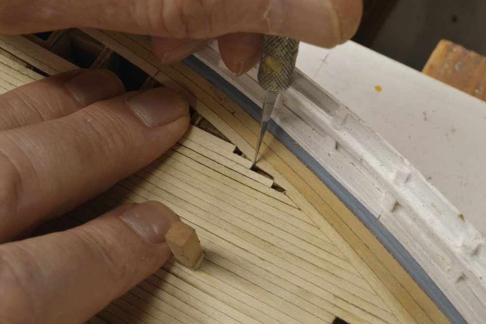
Young America 1853 – POB 1:96 Part 33 – Main Deck Planking continued Completing the deck planking on each side involved fitting the straight parallel planking to the wide margin plank inside the binding strakes and waterways. These members follow the curve of the side. The waterways and binding strakes were structural. The curved margin planks allowed the deck planks to be cut in without damaging the structural inner binding strakes. After the angles of the plank end cuts reached about 60 degrees, further tapering would result in feather edges at the ends that could not be caulked. Forty-five degrees is probably a better guide, but I used sharper angles on these joints that would be completely hidden by the forecastle deck. In the first picture, loose planks are being used to mark the points at which the full plank widths intersect the edge of the margin plank. These marks define the cutting in points. At each of these a knife or chisel cut was made into the margin plank perpendicular to the deck plank ends and one-half of the plank width. The shapes of the required plank tapers can be seen in this picture. Note that the joints get longer going aft, as the curvature of the side becomes less. In the next picture the end has been formed on a plank and it is being marked for cutting out further aft where it meets the main cabin coaming. The next picture shows the plank ends under the forecastle. In this picture the Samson post knee has been installed and the breast beam made and laid across the bulwarks. The bowsprit opening has been enlarged to the required 36” width. In the next picture the main deck planking is approaching completion. The method of cutting the long joint tapers is shown in the next picture. I cut the joints while there is sufficient space for the chiseling - before the adjacent planks were installed. The chisel is a long, straight, model-sized paring chisel – one of my most frequently used and most essential tools. Directions for making these chisels were included in Naiad Volume I. In the next picture a shaped plank end is being fit into its joint. For best visual results the pared side of these planks should be painted like the inner edges – to show the caulk line. I did not do the on this demo model – relying solely on the dark glue to highlight the joint. The next picture shows the very last piece – with a very longer taper – about to be installed. Except for the uncovered hatches, the crude POB framing under the deck was now completely covered – a moment I was waiting for. In the next picture the last plank is in. The deck is still wet in this picture from washing off excess glue. When completely dry, the deck planking was leveled where necessary using the flat rifflers and then sandpaper. I will cover the methods used for fastenings and final deck finish in the next part. Ed
- 191 replies
-
- 37
-
-
- young america
- clipper
- (and 1 more)
-
Beautiful work, Micheal - not something I would ever contemplate at 1:72 or even 1:48. Your right about the brutality of close up photos, but I seen no flaws in yours. Ed