HOLIDAY DONATION DRIVE - SUPPORT MSW - DO YOUR PART TO KEEP THIS GREAT FORUM GOING!
×


EdT
-
Posts
2,213 -
Joined
-
Last visited
Content Type
Profiles
Forums
Gallery
Events
Everything posted by EdT
-
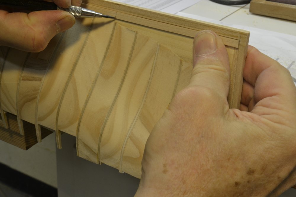
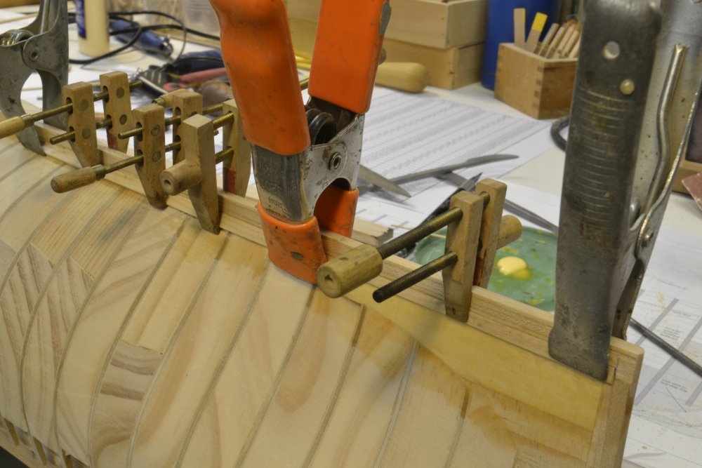
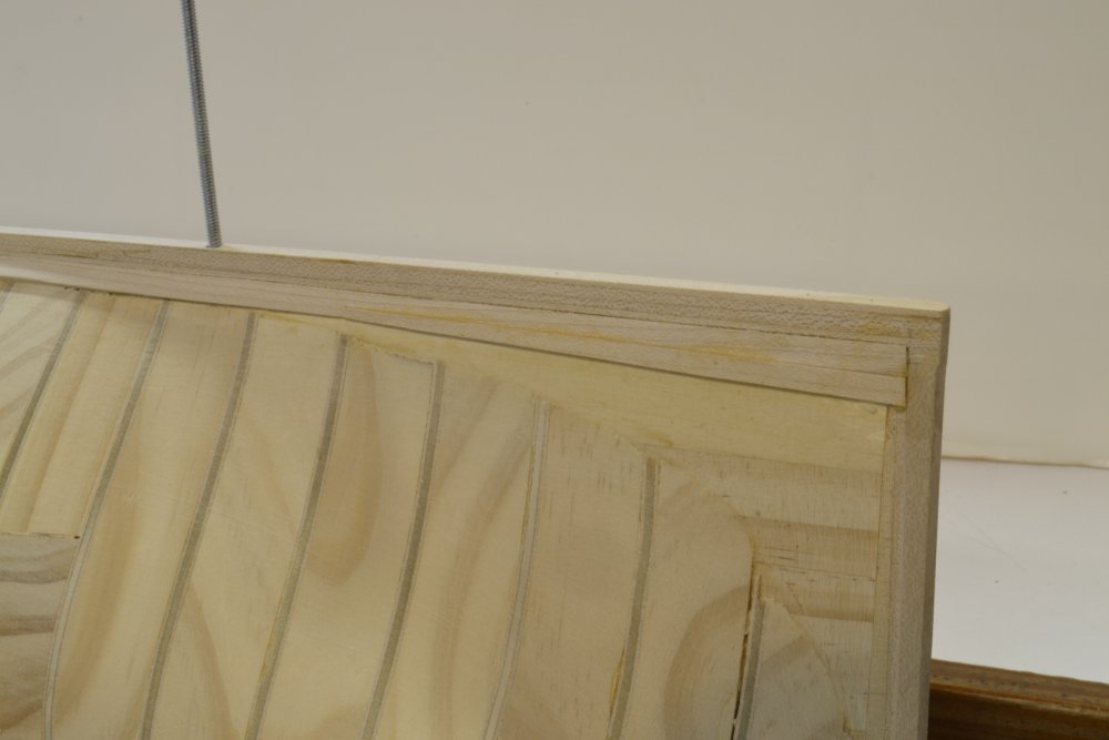
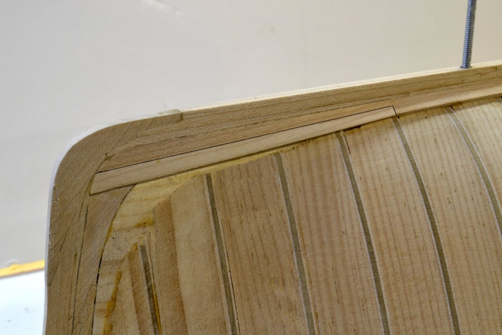
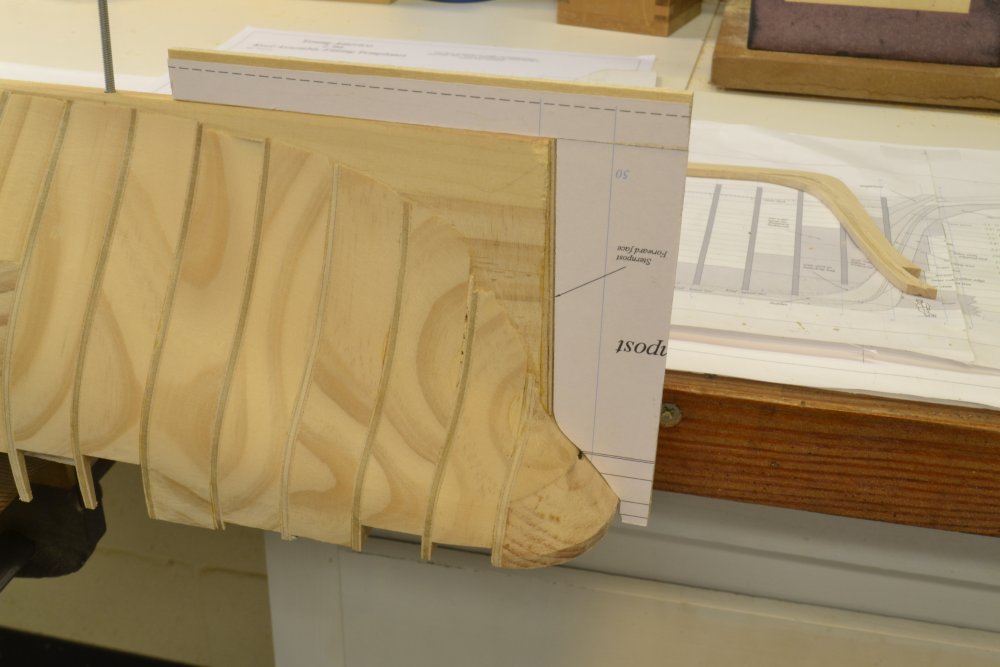
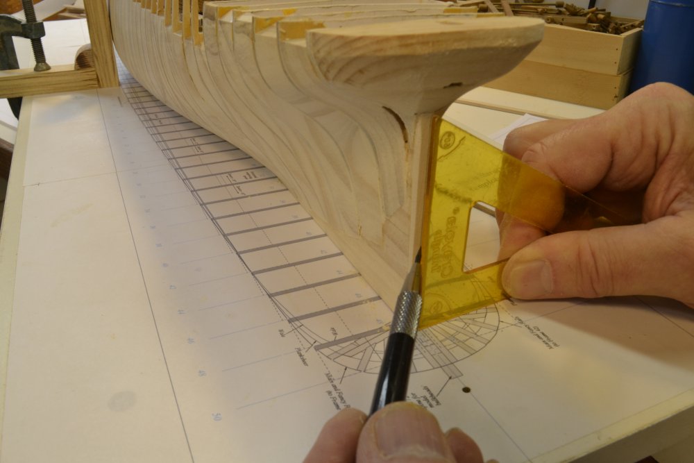
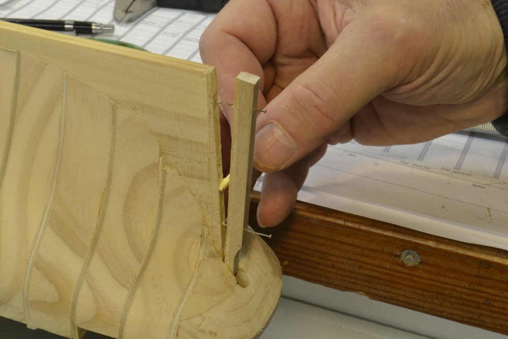
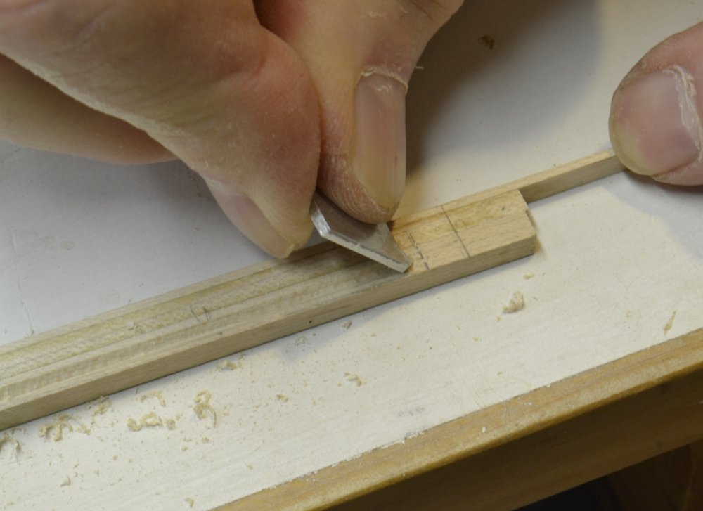
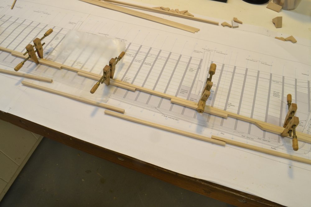
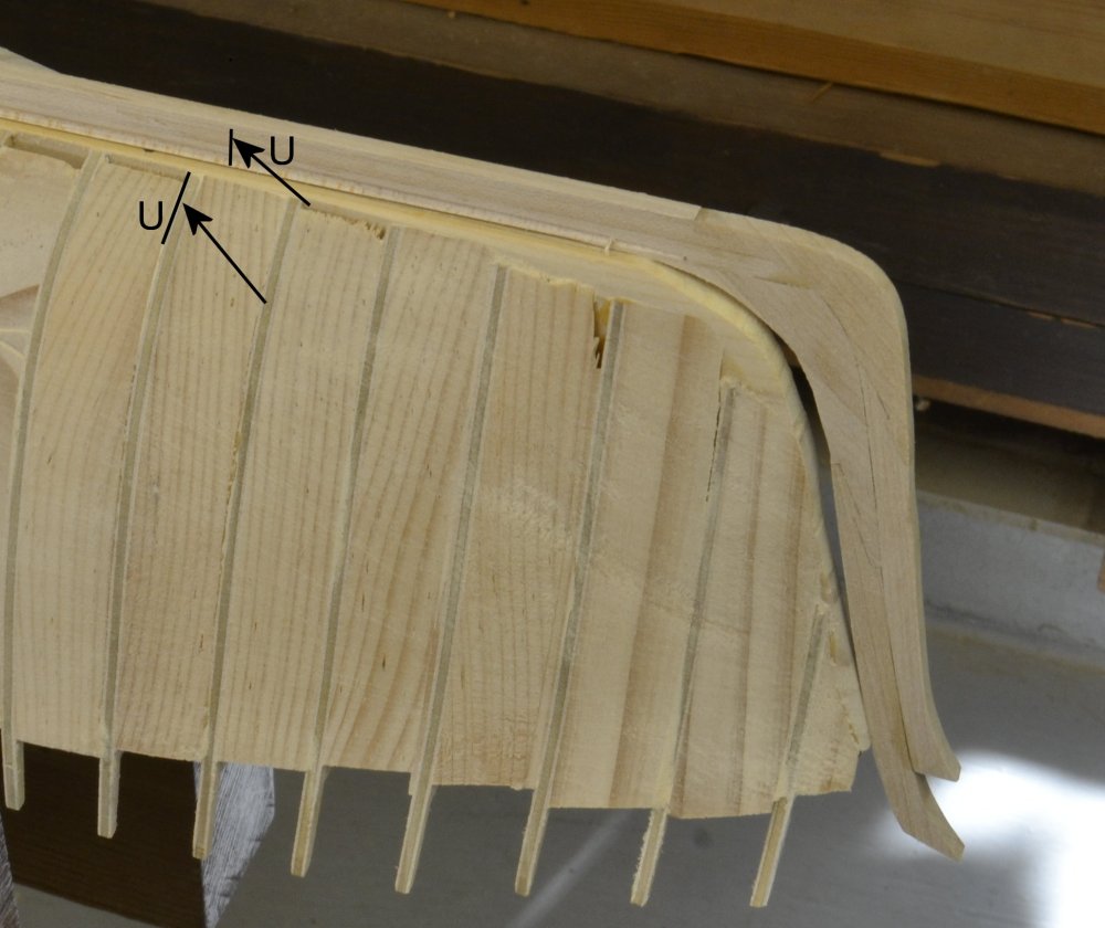
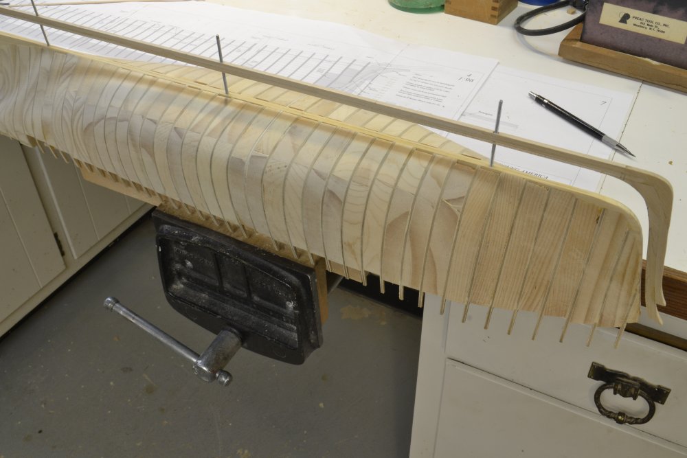
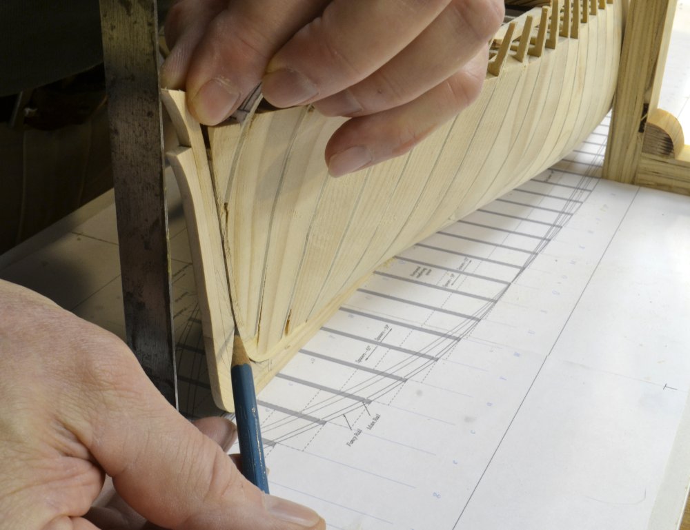
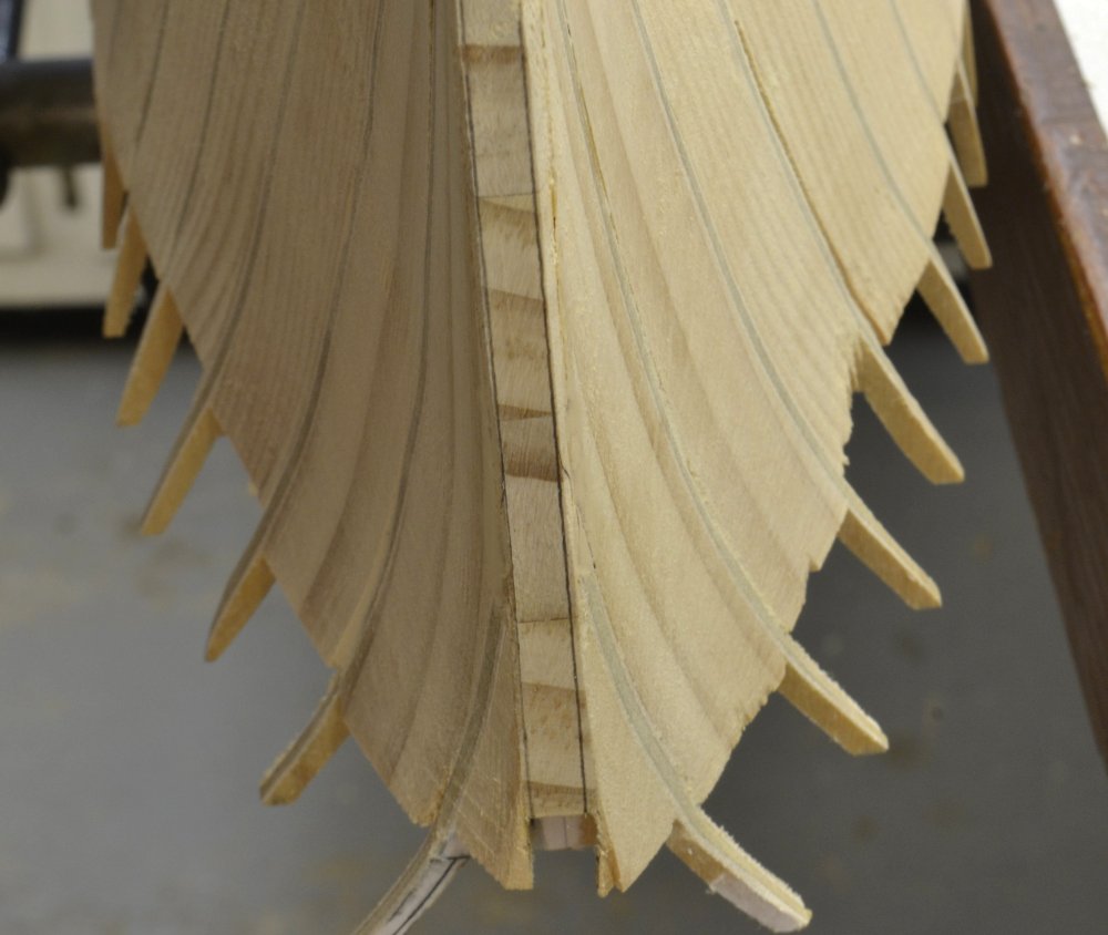
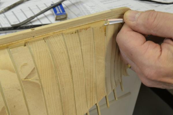
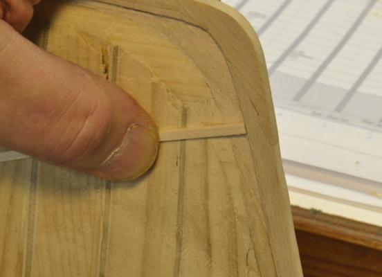
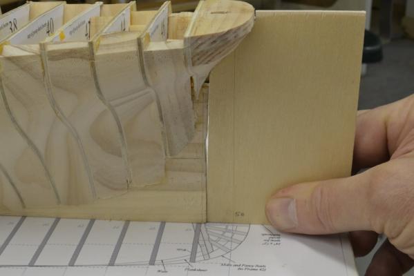
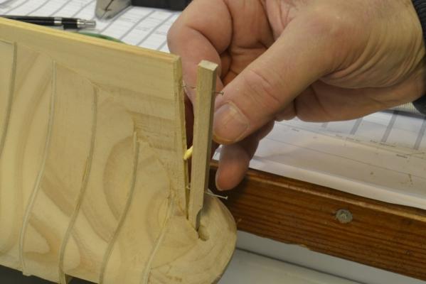
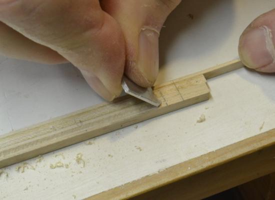
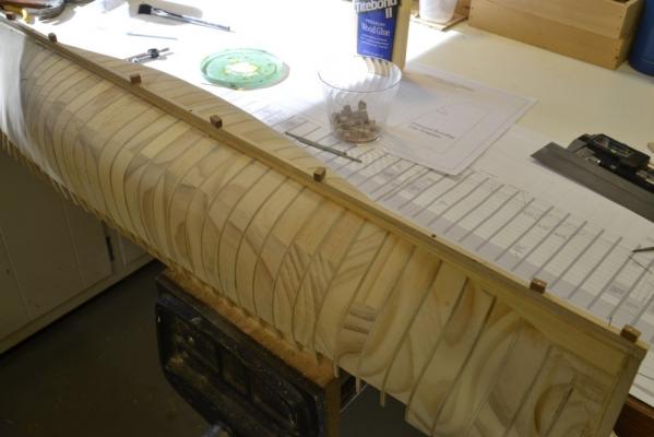
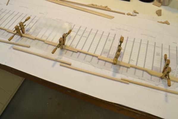
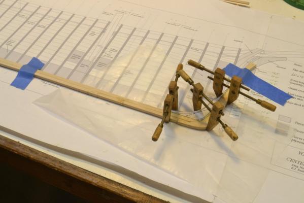
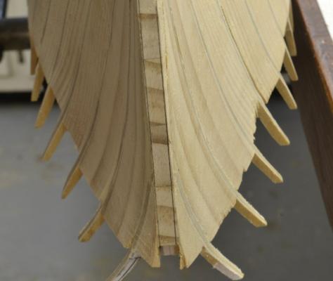
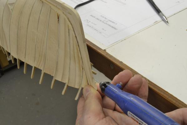
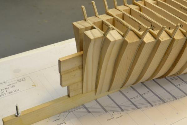
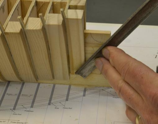
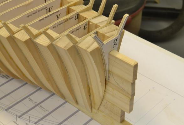
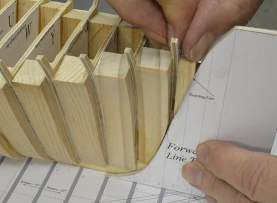
Young America 1853 – POB 1:96 Part 16 – Garboard Strake The planking of the lower hull begins at the keel with the installation of the garboard strake, heavy (7” X 18”) members, bolted through the deadwood and edge bolted into the keel. At the ends of the ship the garboard strake is expanded into two strakes to begin the upward sheer of the bottom planking and to further strengthen to narrow deadwood at these points. In the first picture the aft section of the garboard has been fitted against the post and is being marked for the insertion of the second strake “stealer”. In the next picture the strake was cut to receive the second section and is being held in place to check the final fit.. This strake members were then glued in place as shown below and over the entire length of the hull with a similar joint for a second strake at the bow. Because this strake twists to fay against the curving hull, a lot of clamps were needed. The next picture shows the aft section after the piece of second strake was installed. I did not use dark glue for any of the hull planking since the intention is to paint and sheath the hull later. Hard maple was used for all of this planking. The last picture shows the forward part of the garboard, with the joint lines emphasized on the image to show the configuration. In this picture, it can be seen that the line of the rabbet runs just aft of the joint line between the stem and false stem. Note that in the last two pictures the garboard thins down to match the depth of the rabbet in the stem and sternpost. The garboard was, of course, installed on both sides of the hull at this stage. Since it is intended to sheath this lower hull, I did not install any of the bolts, as I would have done on the fully framed version – if I had installed the garboard on that model. Above the garboard, the planking thickness drops to 4”. The beginning of that work will be shown in the next part. Ed


- 191 replies
-
- 33
-

-
- young america
- clipper
- (and 1 more)
-
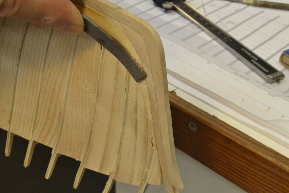
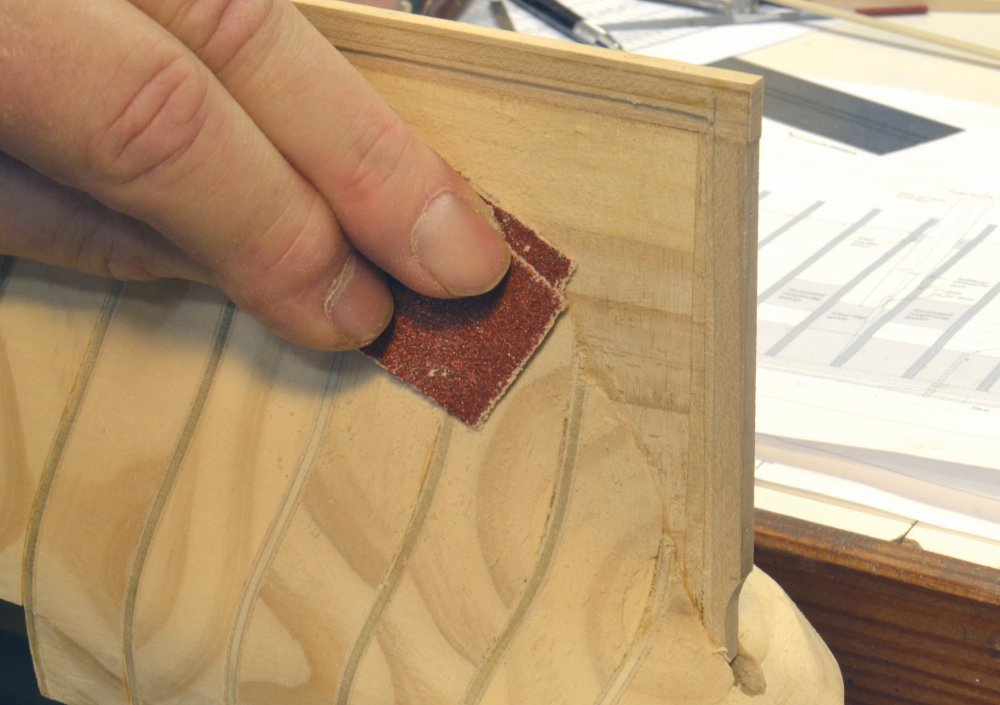
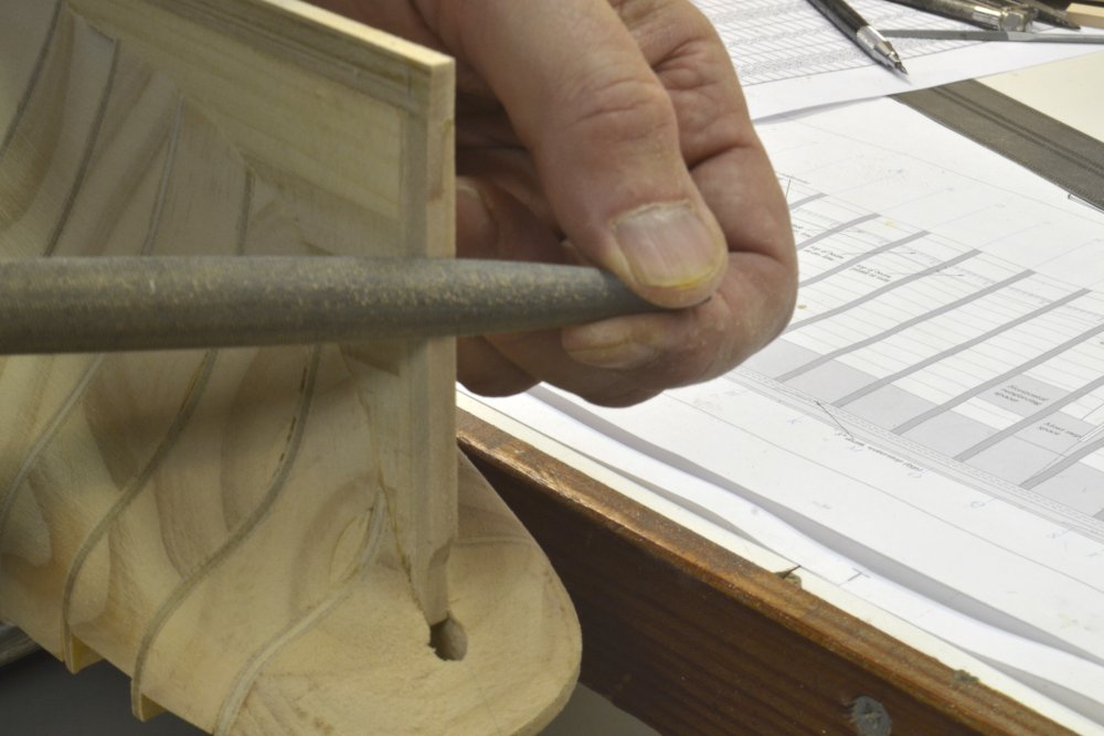
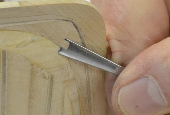
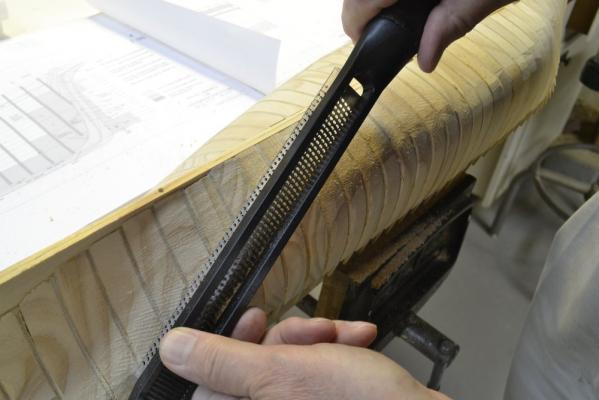
Young America 1853 – POB 1:96 Part 15 – Final Hull Fairing Once the keel/stem/sternpost assembly was installed, the final fairing of the hull into the rabbet could be done. Along the stem and keel the joint with the hull is on the bearding line, so the first step was to fair the hull along this line to meet the thickness of the stem/keel (16”), which is the hull breadth at that line. In the first picture the “hump” on the hull spine is being pared back to match the width of the keel. In the next picture a riffler is being used to produce the final faired surface at the stem. At the stem the area outside of the bearding line must be further pared back smoothly into the stem rabbet that was cut before assembly. In the next picture that is being done with a shallow gouge. In the next picture the fairness in this area is being checked with a strip of planking. The same process was repeated at the stern – and of course on both sides. The hump along the keel at the stern is being removed in the next picture. Sanding is always the final step. The final sanding of the hull was done using 120-grit paper. With the hull now fully faired the bevels on the aft face of the sternpost were filed off as shown below, while the model was inverted. The post bevels allowed the rudder to swing over its full arc without being obstructed by the post. After this work, the lower hull was ready to be planked. And by the way, thanks again for all the likes and especially the nice comments. Ed


- 191 replies
-
- 25
-
-
- young america
- clipper
- (and 1 more)
-
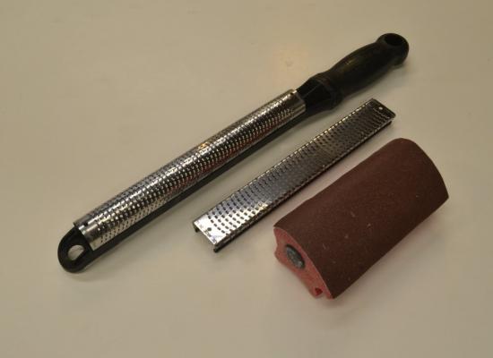
Taoism, Thanks for your interest in the Naiad posts. Its starting to seem like the distant past to me and I am glad to see that the thread can still be found in the long list of build logs on MSW. I cannot explain why the images in parts 170 and 171 are not loading. I cannot get them either. Perhaps the moderators can address this or tell me how I can reload the photos if necessary. The Naiad model is a fully framed structural replica of the original ship – a time consuming project. Yes, three years was about right. Naiad was my second model. My first model, Victory, is also covered in an MSW build log. My current models of the American extreme clipper Young America are also described in two build logs on MSW and are the subject of another how-to-do-it book forthcoming shortly from SeawatchBooks (see below). On to your questions: Very hard woods are used in the model, mainly swiss pear, castelo and European boxwood. This requires pin holes to be predrilled for a tight or sliding fit as required. Where these holes would show on the final model, as was the case with most, they were placed where bolts or treenails would eventually be inserted. The tool in the first photo you showed is a Sherline milling machine fitted with a screw slotting saw blade with the spindle rotated to the vertical position. Sherline makes high quality, small scale machinery. The table saw in the next photo is a Preac 2 ¼” diameter circular saw – my most used power tool for this work. Sadly this machine is no longer available new, but perhaps may be found on ebay. There are a variety of similar good quality model saws available, however. The drawings for the Naiad model were based on the original Admiralty plans for the ship and other contemporary data. Plans for most Royal Navy ships may be obtained from the National Maritime Museum in London. The Naiad drawings were made using a now extinct version of Visio – a 2D CAD application. I am now using TurboCad for this work and all of the drawings for the current Young America project were made using TurboCad. I am not sure what the term “building record” refers to. Two books were published describing the Naiad construction in full detail, including all of the drawings patterns and substantial other information – including a thorough discussion of drafting methods and toolmaking. These books and many other fine books on shipmodeling may be obtained from SeawatchBooks.com. Here is a link: http://www.seawatchbooks.com/ Good luck with your entry into this fascinating craft. Ed
-
Christian, I can only try to answer your questions based on what I learned doing the Naiad drawings and from reading (and rereading, and rereading) Steel and the Repository on preparing drafts. These texts are virtually identical. As I understand the process for placing cant frames, it is as follows - in my words: 1. Determine the number of aft cant timbers (pairs)between the fashion piece and the last square frame. 2. On the half breadth plan set the aft edge of the forward section of the fashion piece (the aftermost cant frame) on a line from its joint face on the end of the wing transom to a point on the deadwood. This point on the deadwood must allow just enough space aft of the last square frame to fit the inside ends of all the cant frames. 3. This line is usually the joint line between the forward and aft parts of the fashion piece pair. The aft section of this frame normally fits under and supports the wing transom. On larger ships there may be more fashion pieces aft of this pair. 4. On the half breadth plan, from the above line, set off equal spaces on the maximum breadth line to the joint line of the last square frame – one for each cant frame pair. 5. Set of the same number of spaces on the deadwood. 6. Draw in the lines of the cant frame pairs between these points and the points on the deadwood. 7. Individual frames of each pair are then placed on either side of these lines so as to provide air space and to accurately define the sides of gun ports in the cant frame area. On multi-deck ships, some jogging of the toptimbers may be necessary - as with square frames at times. 8. By locating the sides of the ports from the sheer plan, the frames on either side can be accurately place on the half breadth plan. 9. The cant frames can then be lofted by taking dimensions to waterlines along the cant frame faces. The forward cant frames are drawn in the same way once the forward fashion piece is placed at the aft edge of the hawse timbers. Care must be taken to eave adequate space along the deadwood to seat all the frames. Another way of looking at this is to set the joint line points on the half breadth at the intersection with the numbered frame lines. Some of Steel’s examples show the lines intersecting these points. Both methods give very similar results. As far as timberheads are concerned, I believe these were normally formed on the heads of the toptimbers that were left longer, above the top of the side – for strength. I would not be surprised to see anomalies on the drafts. It would not be the first I have seen. I hope this is helpful. Ed
-
Hello Cristian, Very nice drawings. Getting the correct shape for the cant frames in the sheer plan view can be tricky business. Did you approximate these or use the actual profiles for this. The process I use for this is to construct the cant frame profile using waterlines along its line on the half breadth plan. Compressing the horizontal breadth of the cant frame profile to the fore and aft distance from its intersection at topside to the intersection point on the deadwood then yields an accurate shape in the sheer plane view. These sheer plane views are mainly for aesthetics, but constructing them is an interesting exercise in 2D CAD - even more interesting if you are manually drafting these. A similar process can be used to accurately represent the shape in the body plan. I found this helpful in lofting hawse timbers. Lovely work. Ed
-
Nils, You may also want to experiment with the hardness of the surface below the foil when embossing the rivets. Harder material will decrease the rivet size and height. The model looks great. Ed
- 2,625 replies
-
- 4
-
-
- kaiser wilhelm der grosse
- passenger steamer
- (and 1 more)
-
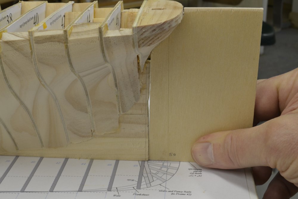
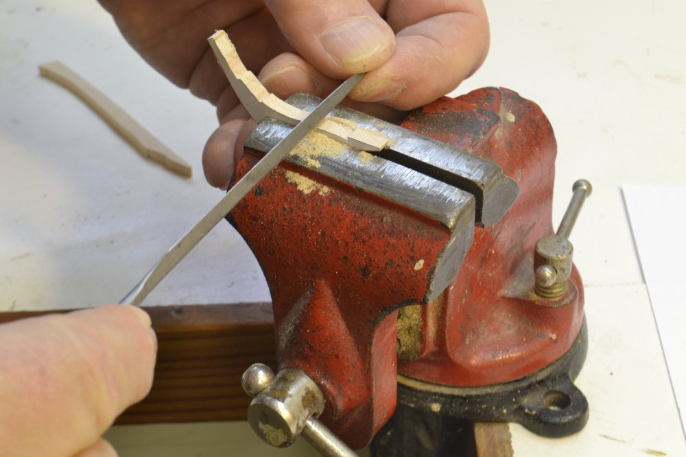
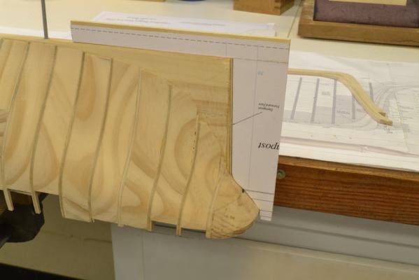
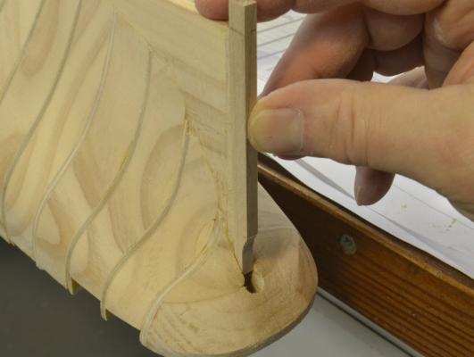
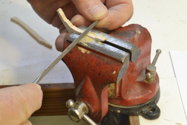
Young America 1853 – POB 1:96 Part 14 – Stem/Keel/Sternpost 3 Before attaching the keel/stem assembly to the hull, the sternpost had to be installed. In the first picture a template is being used to check the hull for fitting the post. The template is aligned at station 50. The picture shows the need for a filler piece. In the next picture the hull has been cut back for the filler, it has been installed, and the hull is being checked again with a different template. The filler piece provided a straight, flat surface on which to bed the sternpost – assuring a good joint and clean surface for shaping the deadwood into the sternpost rabbet. In the next picture, with the hull plumbed, the sternpost centerline is being marked on the filler. In the next picture the hull has again been inverted and the sternpost is being fit up. Holes for locating pins were drilled with the post in position. The bottom of the post was then cut off flush with the bottom of the hull. In the next picture the sternpost rabbet is being scraped out using the vise as a guide. The rabbet was formed on both sides in this way – all the way to the bottom of the post up to the intersection with the hull at the top. In the next picture the post is being glued to the hull. The keel assembly rabbet was extended only back to the inner line of the post, as shown below, deferring final rabbeting until after assembly. In the last picture the stem/keel assembly is being glued to the hull and held in place with pins driven through wood blocks. The hold down bolts were in position for the gluing/clamping, but were removed to avoid them being glued in. The next step was to fair the deadwood into the rabbets at both ends – next time. Ed

- 191 replies
-
- 26
-
-
- young america
- clipper
- (and 1 more)
-
Beautiful work, Danny - and an outstanding build log. I look forward to your next project. Ed
-
Nice work, Frank. Taking pains with the little process details - to say nothing of your skillful work - has paid off in a beautiful model. Ed
-
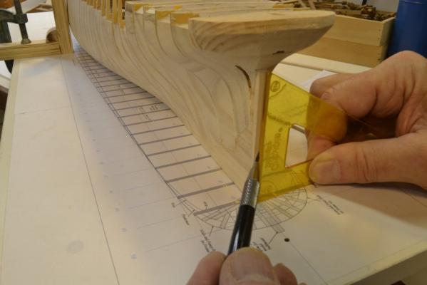
Young America 1853 – POB 1:96 Part 13 – Stem/Keel/Sternpost 2 The keel for this version of the model was made exactly like the keel on the framed version – in two tiers plus a shoe and with hooked scarph joints – but without the water stops and joint wedges. I did not take pictures of the joinery work. This was described in the posts for the framed version. The first picture shows the upper tier being glued together using strips of wood to keep it straight. The pieces of the lower tier are shown below the glued assembly before their joints were cut. In the next picture the keel assembly with the two tiers and the shoe has been glued to the false stem assembly and the stem is being glued into the angle between the two assemblies. The stem and keel were taped to the drawing to preserve alignment when fitting and gluing the stem into place. The stem provided enough reinforcement to prevent to stem shape from distorting in the next steps. In the next picture the stem/keel assembly has been fit up to the inverted hull for final fitting. It can be seen in the picture that some shaping of the forward hull is needed. This was left rough and slightly large. The station marks accented in the picture were used to get the assembly correctly positioned as the forward curve of the hull was trimmed. In the next picture the fitted assembly has been drilled with mounting bolt holes to match those on the hull and is being test fit. With the stem/keel still unglued, the hull was bolted down on the shipway and plumbed so the stem could be centered. The next picture shows the hull being marked to show the sides of the stem. This allowed the forward deadwood to be trimmed to match the stem while the stem was removed and safe from damage. The next picture shows the fairing to the stem sides. The stem was next refitted and aligned to the marks so locating pin holes could be drilled as shown in the next picture. Before attaching the stem/keel assembly, some additional work was required at the stern – to be covered next time. Ed
- 191 replies
-
- 25
-
-
- young america
- clipper
- (and 1 more)
-
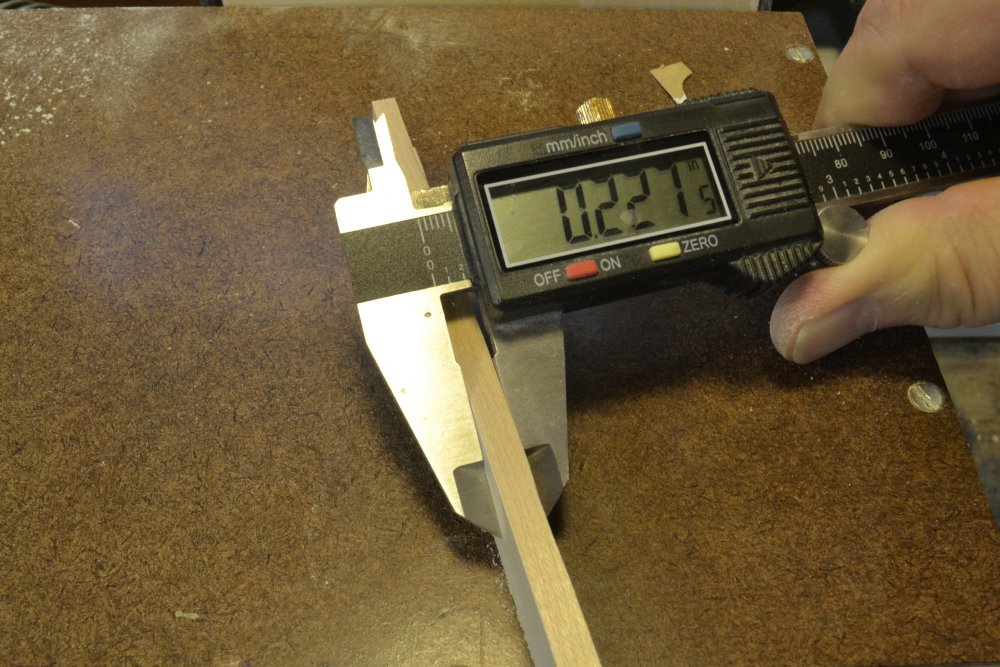
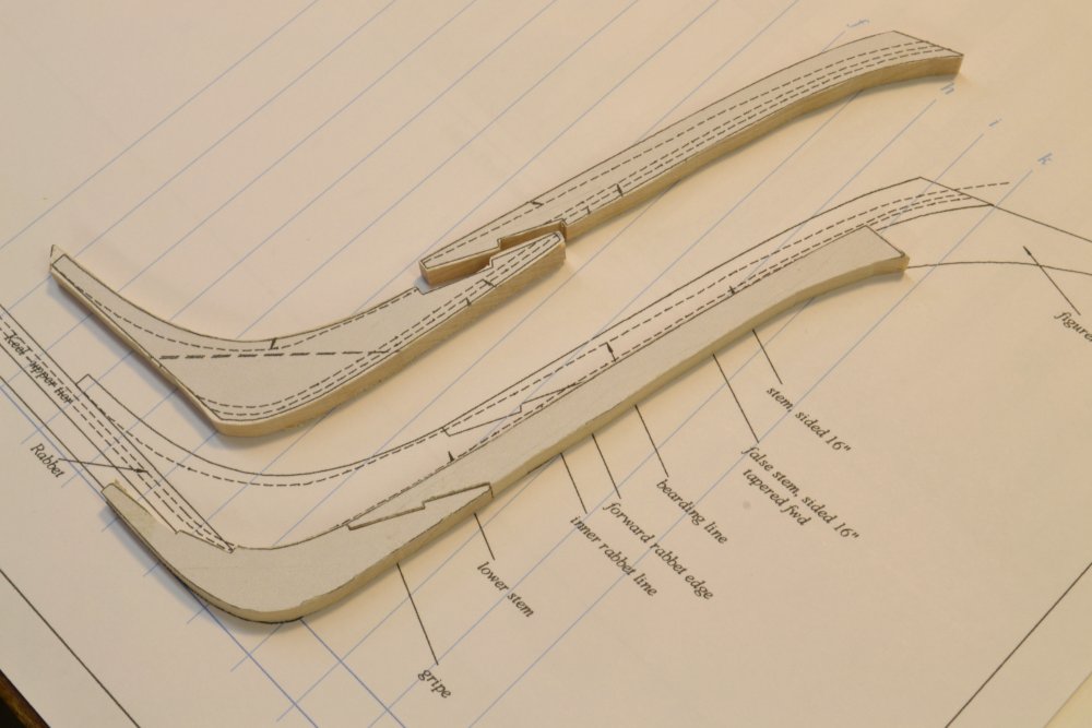
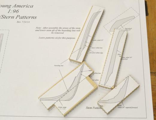
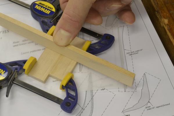
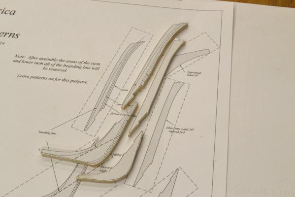
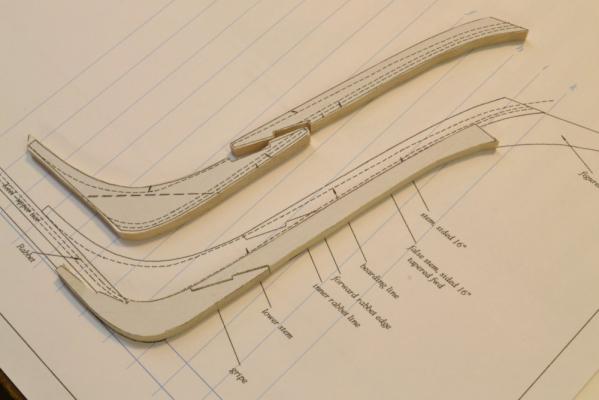
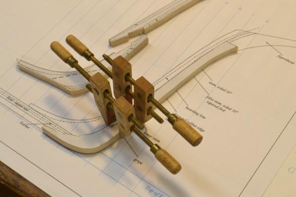
Young America 1853 – POB 1:96 Part 12 – Stem/Keel/Sternpost 1 The stem assembly, keel and sternpost on the POB model are virtually identical to their counterparts on the framed model except for scale and the deletion of a few unnecessary internal structural parts. Unlike the framed version that started construction with this work, on the POB model they were made and installed after the hull was shaped. In keeping with the concept of simpler tools and readily available materials for this version, scale members were all cut from ¾” (4/4) material. For the stem/keel/sternpost, hard maple was used – with pieces selected for straight grain. Becaused of its visible grain pattern I would only use maple where work will be painted or metal sheathed. The POB model did not require the thickness sander or band saw. Members were sized using circular saws. If ¾” hardwood can be ripped on an available 4” model circular saw, ripping stock to required dimensions is just a matter of setting the rip fence and cutting. On the full-sized (10”) table saw that I used, a different method was adopted. The first picture shows stock for the 16” wide keel about to be ripped off of a piece of 3/4” maple. Although cutting sized strips away from the rip fence as shown takes a bit more setup time, it is much safer and eliminates damage to small thicknesses left between the fence and the blade. It also avoids having them come out of the saw at high velocity. The blade in the picture is an ultra-thin kerf (.080"), 40-tooth carbide blade that leaves a very clean surface on the strip. The Plexiglas® table insert was specially made for close clearance to this blade. The next picture shows the ripped 16” strip being checked for size. I usually start with a very small cut into the plank and measure what will be the resulting strip thickness, then adjust the fence if necessary before cutting off the whole strip. This was then repeated for each cut. The ¾” strips were then used to make sections of the keel and the other components. In the next picture the POB stem pieces are shown on a copy of the pattern sheet. All were able to be cut from the ¾” inch stock except for the lower stem as shown above. On the original ship this piece would have been cut from a very large piece of compass timber – probably live oak for strength. On this model, two pieces of edge-glued ¾” maple were used. The next picture shows the two pieces used for this being edge glued. Undarkened Titebond® was used for this to minimize joint visibility, although on this model all this will be covered by metal sheathing. The long straight piece in the picture is being used to make sure the two glued pieces lie flat. The next picture shows the four stem pieces cut out and ready for fitting. Dashed lines around the patterns show ¾” stock. The pieces were cut on the scroll saw very close to the pattern lines, then dressed with a file for final fitting – as shown below. The patterns were left pasted on for all of this work. In the next picture,, the false stem (the members forward of the stem proper) have been fitted and aligned on the drawing. The false stem pieces are being glued in the next picture. Alignment is again provided by the drawing. To be continued… Ed


- 191 replies
-
- 29
-
-
- young america
- clipper
- (and 1 more)
-
Beautiful work, Dany - with extraordinary attention to the small details. To add to the comments on the stern lights: There are two potential problems with outswinging sash, both caused byt he slant of the stern. Both upward and side opening sash would have to clear the lower sill. Ed
-
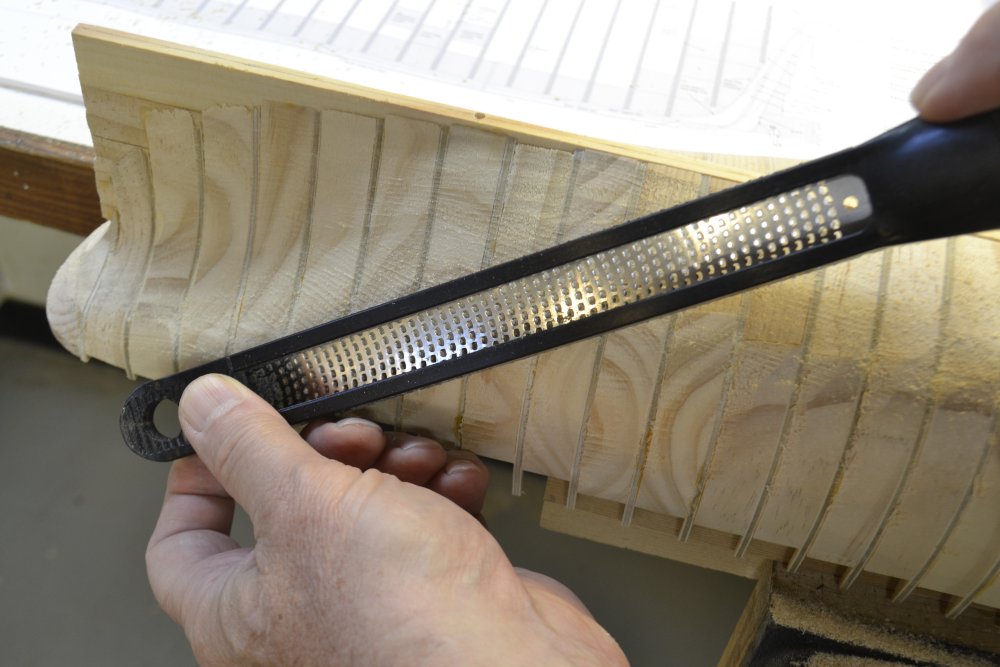
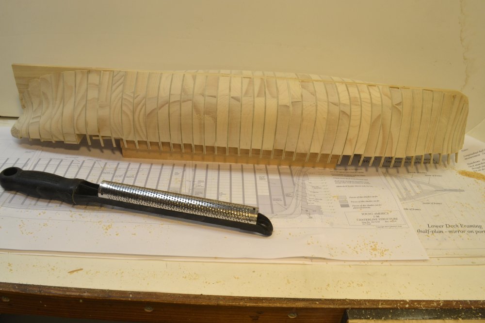
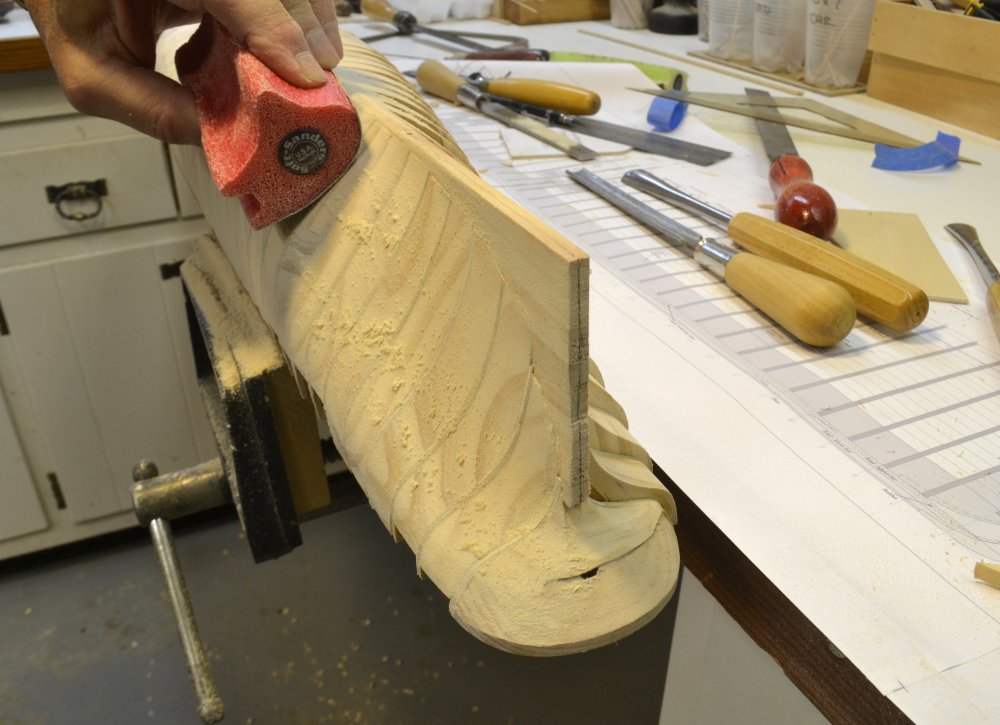
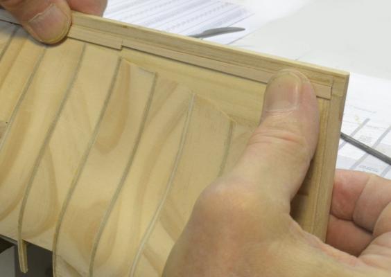
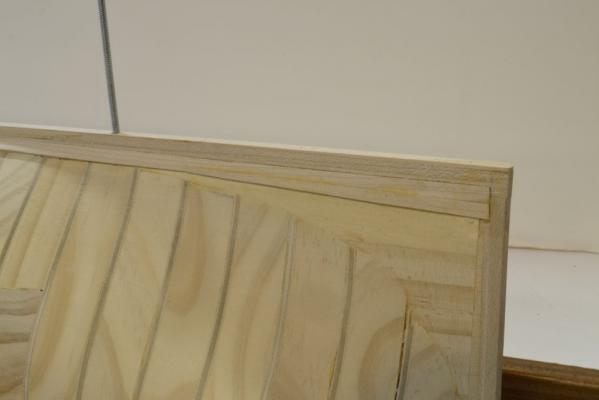
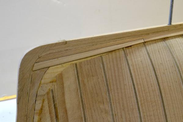
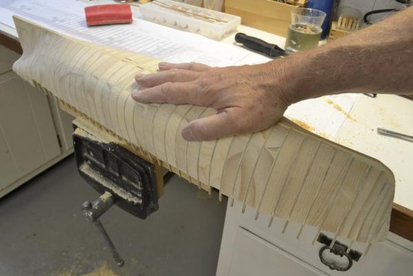
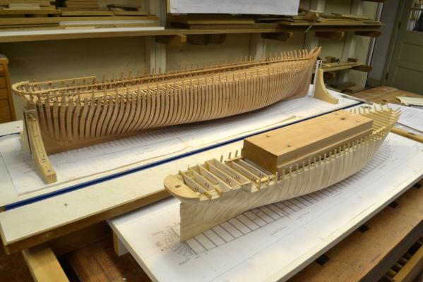
Young America 1853 – POB 1:96 Part 11 – Hull Fairing – Method 2 For those who may have missed it, this POB model was initially built for demo purposes for Volume I of the book – to provide a smaller, simpler version for those less interested in the fully-framed larger model. I have since been taking the construction further than planned and do not yet know how far that will go, but the project has been interesting and I am very pleased with the POB framing method used and the results so far. Since the model is supposed to be simpler and more interesting for less experienced modelers, I tried to use fewer and simpler tools where possible. I do not put the carving gouges or the rasps used in the last part – or the necessary sharpening stones - in that category. So, for the port side of the hull I used some much less expensive and easy to use tools. These are shown in the first picture. The primary tool here is the Microplane®. This tool is inexpensive and very easy to use. It worked very well on the pine of the spacers. The tool comes with both flat and curved blades. These can be fitted to allow either push or pull strokes. I used mainly pull strokes that seemed easier to control. The next picture shows the curved blade being used on the convex part of the stern. In the next picture the flat blade is being used on a convex surface. When the spacer material was removed, the final surface was produced with the Softsander® as before using 120-grit paper. In the next picture the work is just about finished and I am appreciating the smooth feel of the faired hull. As with the starboard side, this side also took less than 2 hours work. The next picture shows the hull out of the vise and the curved Microplane®. The next picture shows the hull next to its big sister. The next step is to make and install the keel/stem/sternpost on to the POB hull. Ed


- 191 replies
-
- 29
-
-
- young america
- clipper
- (and 1 more)
-
George, I believe with a solid hull it is customary to work with external templates or to waterlines on lifts - or both. Much depends on the accuracy you wish to achieve. In the method shown, the accuracy is obtained by fairing to the precisely shaped plywood bulkheads. With one of these at each station - 41 total - a very accurate hull shape is quite easily obtained. Using external templates is a more tedious process and requires templates to be squared up when paced against the side. Using lifts alone requires interpolation of the shapes between waterlines. I did this once, many years ago and found precision difficult to achieve. Also, I am not using any filler material on the wood. Ed
- 191 replies
-
- 7
-
-
- young america
- clipper
- (and 1 more)
-
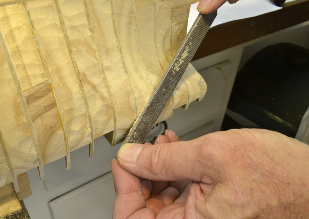
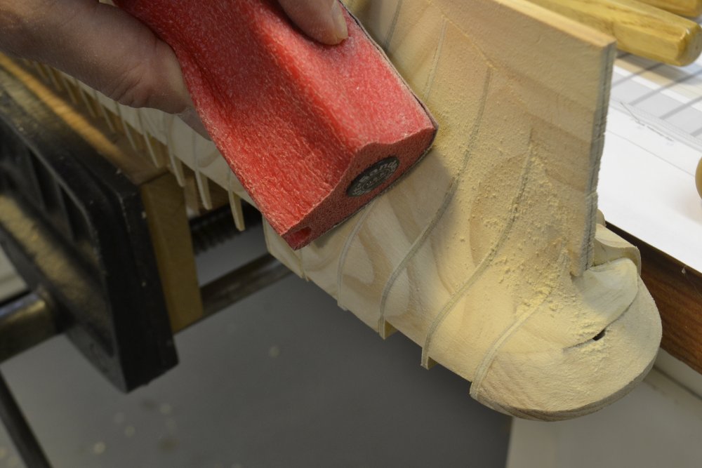
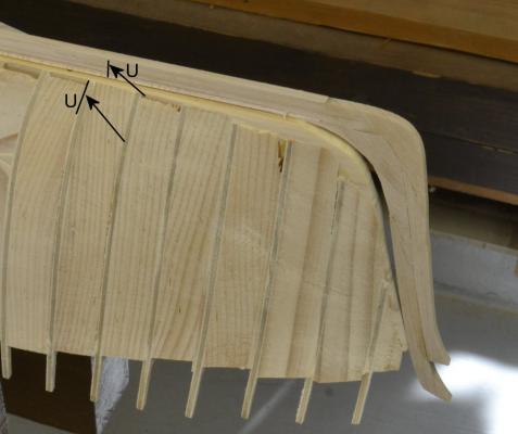
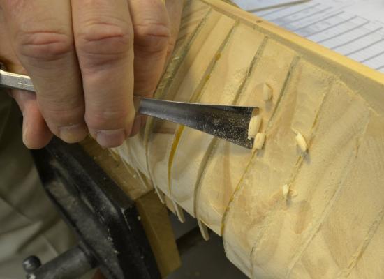
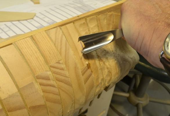
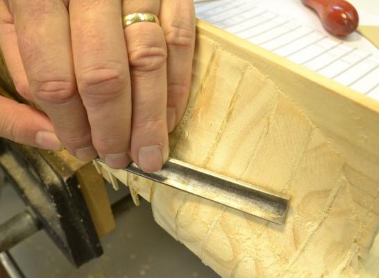
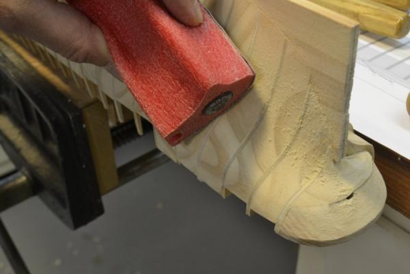
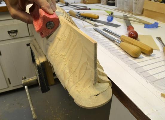
Young America 1853 – POB 1:96 Part 10 – Hull Fairing – Method 1 As seen in some of the previous photos, there is quite a bit of wood to be removed from the spacers used in this framing method. It is much like working on a solid lift type hull, but the numerous bulkheads make it very easy to accurately duplicate the original shape by merely removing wood down the each of the bulkheads then finishing it off to a smooth fair surface. My natural response to this work was to use available carving tools to remove wood between bulkheads, followed by rasping and sanding. This is a good method to use if you have the tools and the ability to keep then razor-sharp. However, although I used this method on the starboard side, I wanted to offer a simpler process, using less expensive tools on the opposite side. That second method will be described in the next part. The first picture shows shavings being pared off the hull using a shallow curved gouge with hand pressure. A solid anchoring of the hull is essential to allow two hands for this work. The sharp gouge easily removes thin cross-grain shavings. In the next picture a deeper gouge is being used with a mallet to chip off larger pieces of the extreme bevels near the stern. Again, this requires the hull to be firmly secured. After paring with the gouges the shape was further smoothed out with fine-cut rasps. The curved rasp in the next picture was used on the concave surfaces. A flat rasp was used on the convex hull surfaces as shown in the next picture. The rasps used here are fine-cut Iwasaki® carving rasps. This is not a job for the coarse hardware-store variety. You can pay almost anything for a rasp. These are good quality and reasonably priced. The last step on this side was done with 120-grit sandpaper on Softsander® pads – as shown in the next two pictures. The rasping and sanding bevel the plywood bulkheads as necessary to leave a smooth surface. This involves trimming only the small side of the plywood shapes. This point is indicated by feel as well as sight. The above picture shows the finished and unbeveled sides and gives an idea of the amounts of wood to be removed. This work went pretty fast, taking less than 2 hours for this side of the hull. A second method will be shown on the port side in the next part. Ed

- 191 replies
-
- 28
-
-
- young america
- clipper
- (and 1 more)
-
John, There are two different species of pine used on my POB model - sugar pine and radiata pine. I used what I had available from my collection of leftover stock. As I mentioned earlier, the sugar pine is much preferred for its uniform softness vs. the radiata which has hard, darker growth rings that make shaping and especially pinning planks somewhat more difficult. Sugar pine (pinus lambertiana) is a western species prized for its stability and consistent density. It is easy to work and is/was widely used for pattern making for castings for that reason. The consistency of density makes it hard to distinguish distinct growth rings. You will probably need to go to a "real" lumberyard to find it. I found a description of it at the following link: http://www.na.fs.fed.us/pubs/silvics_manual/Volume_1/pinus/lambertiana.htm Radiata pine (pinus radiata) is a form of Monterey pine grown in certain areas of southern California and Baja Mexico. It is highly cultivated for various construction uses and can be found in home centers like Home Depot or Lowes in the form of clear boards. It is usually labelled Radiata. I probably bought this for some carpentry project and used it on the model for convenience. It serves the purpose but is not ideal. In addition to the hard rings, dimensional stability is variable and planks sometimes perform contortions before long - not too much of a problem on small pieces, but shrinkage could be. Species identification of your available stock may be difficult. There are many pine species. Given your location, it may be eastern white pine - a common species in the northeastern US. I would not hesitate using this if clear and straight grained. I hope this helps. Ed
- 191 replies
-
- 6
-
-
- young america
- clipper
- (and 1 more)
-
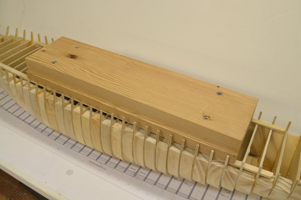
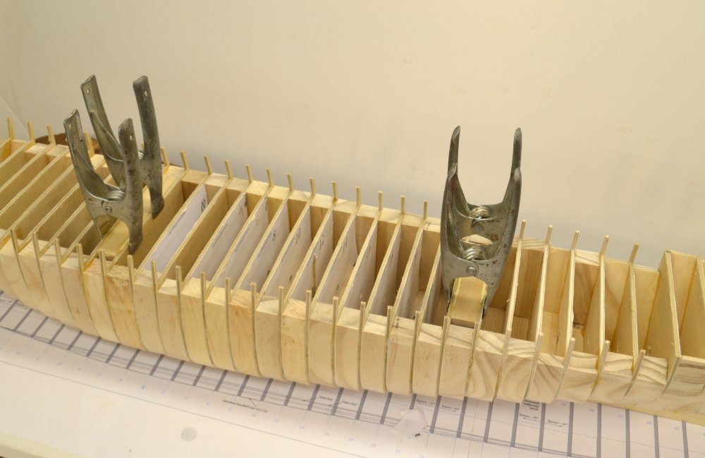
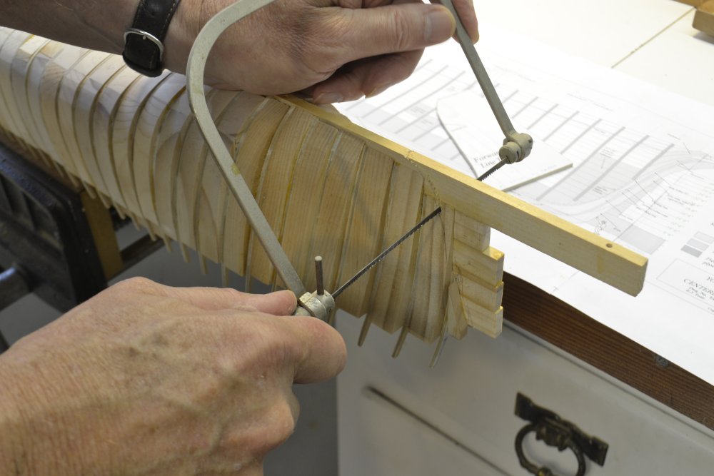
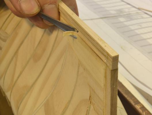
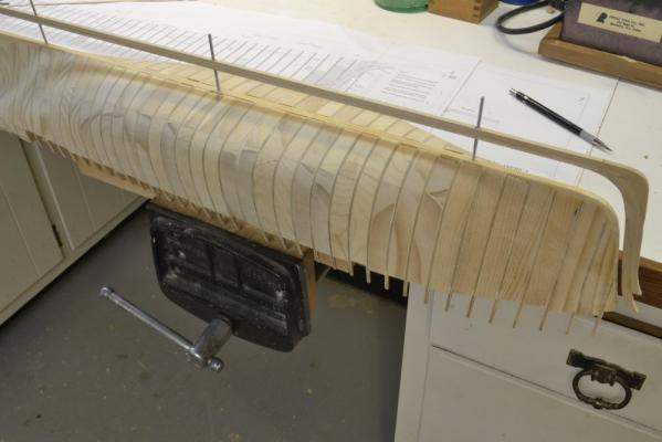
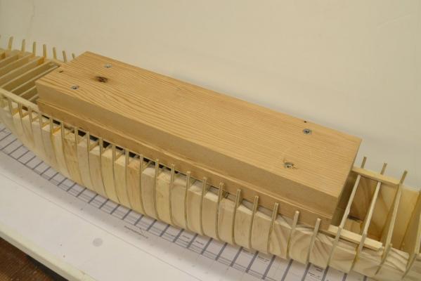
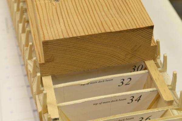
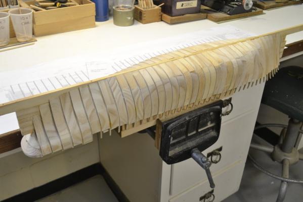
Young America 1853 – POB 1:96 Part 9 – Support for the inverted hull The hull of the model is very strong and solid – except for the fragile plywood toptimbers. Since there is a lot of work to do with the hull inverted, some form of robust support was needed - to support the hull for heavy work like fairing, but at the same time to keep the toptimbers protected. A heavy wooden block that could be securely fastened in a vice was made and attached to the hull for this purpose. It is shown screwed down to the “deck beams” in the first picture. To secure the block to the hull a pair supporting spacers were fitted and glued between bulkheads – away from later facilities. These are shown glued and clamped in the next picture. Four long wood screws were used to fasten the block to these supports. The wood block was rabbeted along the sides as shown below to keep the toptimbers clear of the vise jaws. Two strips of wood were used to keep the block from rocking on the round up of the deck. The next picture shows the hull securely clamped in a bench level woodworking vise ready for the next steps. Removal of the excess spine was the first of these steps. In the next picture a coping saw is being used to cut just outside of the bearding line previously marked on the forward part of the hull. The spine aft of the post was also removed by cutting on a line marked from a stern template. Both these cuts are rough at this stage. After this work the hull was ready for fairing – to be covered in the next parts. Ed


- 191 replies
-
- 27
-
-
- young america
- clipper
- (and 1 more)
-
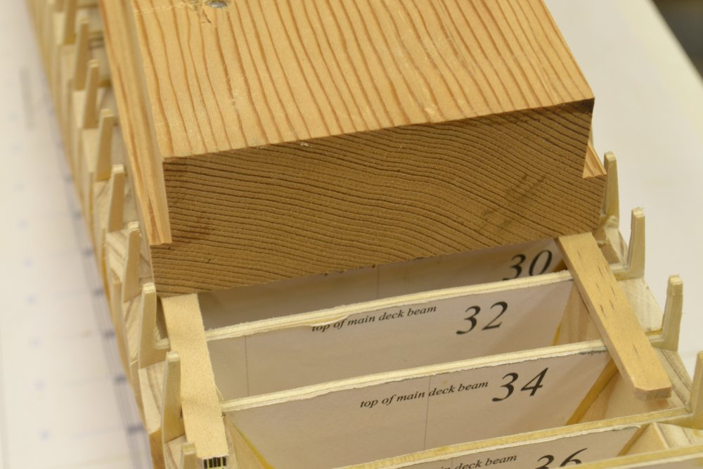
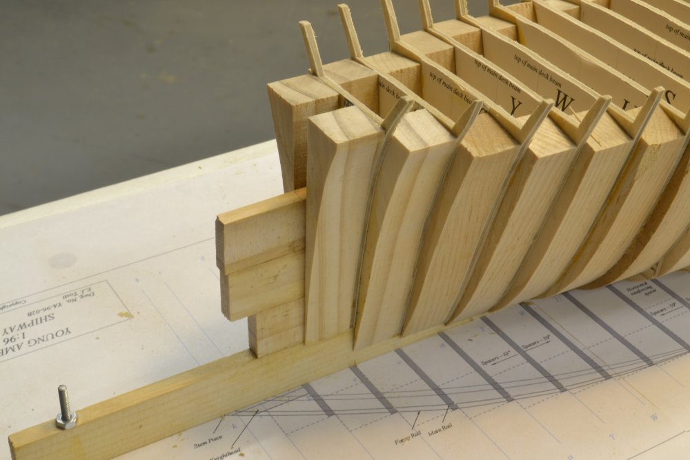
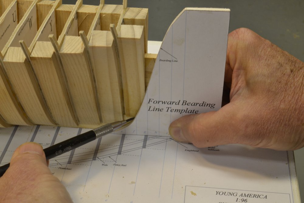
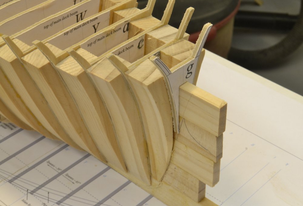
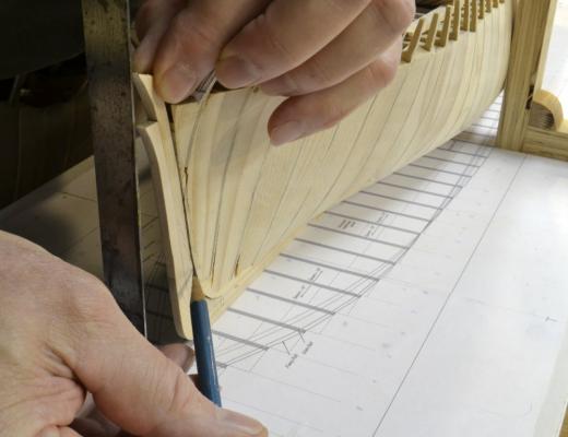
Young America 1853 – POB 1:96 Part 8 – Bow As with the stern, the bow required some solid support forward of the last bulkhead. The first picture shows the bow before the last bulkhead at frame g had been set. The line of the stem was first roughly drawn on the hull using a template as shown below. This template was used on both sides by marking one of its frame lines on the opposite side. The line is rough at this stage – slightly on the full side. This will later be adjusted and the stem/keel assembly fit over this. In the next picture the forward spacer is being shaved back below the bearding line. This allows the template to be more accurately placed flat on the deadwood for more accurate marking. The extreme bevel of this last spacer can be seen in the next picture, taken after setting bulkhead g. There is a lot of wood to remove from these forward spacers. In the next picture a small pine block is being fitted between bulkhead g and the spine with its lower face on the bearding line.. The breadth of the hull at the bearding line is the breadth of the deadwood – 16” on this ship. The spine is larger than this at ¼” = 24”. This leaves some allowance for final fairing. These forward pieces are temporary, to be removed and replaced later with the knightheads and stem pieces. Their purpose at this stage is to protect the plywood of bulkhead g from being damaged when the forward hull is fared. Ed

- 191 replies
-
- 29
-
-
- young america
- clipper
- (and 1 more)
-
By the way, let just add a point here lest someone wants to try this method using rubber cement to secure paper patterns. The rubber cement residue that would be left on the plywood surface when the paper is removed would prevent the absorption of the wood glue that is critical to the joint. Even with solvent cleaning of the glued area this would be a concern to me. Those that follow my work know that I am no fan of rubber cement. This is but one reason. Ed
- 191 replies
-
- 7
-
-
- young america
- clipper
- (and 1 more)
-
John, You are absolutely right. If left on the bulkheads, the paper would prevent a good bond with the spacers and the hull would be weak. The glue joints between the plywood bulkheads and the spacers is the main source of hull strength. The notch over the spine is glued but that does not provide much strength. It is primarily for alignment and setting the heights of the frames. I remove the paper wherever there is a glue joint, for example in the area of every spacer. When locating the spacer on the bulkhead I scribe a line through the pattern, then wet the part to be removed and rub it off. Using school glue paste sticks allows this simple removal. A damp paper towel serves to clean off any residue that might interfere with the glue. Because I scribe the line right at the edge of most spacers, it may appear that the spacers are glued to the paper - not so. I leave the rest of the patterns on so I can quickly identify the frame numbers and use the pattern centerlines. I do use the technique you describe for holding pieces together to allow identical cutting, but for these small parts I do not bother with the paper. The school glue is enough. It might not be enough for turning, but works well for matched cutting on the scroll saw. I will show that when I make the carrick bits and may have shown it for those parts on the framed model. Jan, what you say about planking adding strength is quite true. When glued to the outside of the hull the planking reinforces the plywood/spacer joints and also any plywood delamination. Good point. Ed
- 191 replies
-
- 8
-
-
- young america
- clipper
- (and 1 more)
-
Frank, I am hoping so too. If the book is out in time, I hope to be there with both Young America models. We'll keep our fingers crossed. Ed
- 191 replies
-
- 3
-
-
- young america
- clipper
- (and 1 more)
-
Thanks, everyone, for the likes and comments. On to the questions: Peter, I believe basswood would work as well, but it is harder than white or sugar pine. I believe it is more expensive than sugar pine, but I have not checked that. I usually have some 1" x 8" clear sugar pine on hand, so that was convenient to use. Unfortunately, the Radiata was also too available - on hand from an earlier carpentry project. I am never quite satisfied with wood from the "big box" home centers and prefer to go to a real lumberyard if one can be found. I believe clear white cedar would also be good for this - although this "pencil wood" is sometimes hard to find. The softness of the spacers makes cutting the 3/4" thickness on the scroll saw easy. Also, later it will facilitate clamping on the planking - I used thumb tacks. The aircraft grade plywood I used was 3/32" three-ply birch. The plys are at right angles. I aligned the outer ply grain vertically to make the top timbers stronger. In all of the bulkheads I found zero voids and zero delaminations - well worth the price. I ordered it online - two 24" x 48" pieces - more than enough. Rob, thanks for your continued interest in the books. Hopefully you will not have long to wait. Volume I covers the hull construction for both the framed and POB versions. It describes construction to about the time of launch. We expect Volume II to cover fitting out and rigging. This should include the above deck facilities like deck houses, capstans, wheel, ladders, pumps etc - then masting and rigging. In volume I, construction methods for both versions converge to common descriptions. I expect rigging to be scale neutral, but I am just putting together the way that will be done. Ed
- 191 replies
-
- 6
-
-
- young america
- clipper
- (and 1 more)
-
Laman, I don't know what I could have been thinking when /I wrote the notation on Frame 6f pattern, It should read " Third futtock centered on lower futtock. Upper futtock aft face on third futtock aft face." I apologize for the garbled note. These notations are often cryptic at best. If in doubt about these, consult drawing 3, the framing elevation. This shows the alignment of futtocks on each frame. These duplicate the futtock alignments on the original Admiralty draft. For the frame scantlings, consult the Notes and Dimensions for Drawing 3 (PDF) on the CD. You will see that the 4th futtocks are sided 11" and the toptimbers 10.5" diminishing to 10" at the top of the side (not 'sided' as written) and at the tops of the upper futtock heads. These notes and dimension sheets are the primary reference for dimensions. As a matter of interest, I took the 10.5" dimension from The Shipbuilder Repository 1788. Steel gives this dimension as 11" for 38 gun frigates. I am very glad you are finding the books useful - and especially glad to hear you find them easy to follow. I wish you a successful build of Naiad and would love to see some pictures. Why not start a build log? Sailing on the Sea Cloud sounds like a great experience. 11 knots is about the fastest speed measured for Naiad. Did you go aloft? Ed If you have not already done so, I suggest printing all of the drawing Notes and Dimensions sheets and keeping a copy in the shop for easy reference as you work.
-
The hull looks beautiful, Nils. I am looking forward to your further progress. I love these liner models. Ed
- 2,625 replies
-
- 5
-
-
- kaiser wilhelm der grosse
- passenger steamer
- (and 1 more)
-
Peter, Thanks for your interest. This version of Young America does require less tools than the framed model. Everything is described in full detail in the forthcoming Book describing construction of both versions. It should be out soon. Keep an eye on SeaWatchBooks. I have just finished planking the hull, but I want to work through the sequence so I will describe that later. It was a breeze - very easy with very good results. I am very pleased with the POB framing method used. I could be adapted to any model. Ed
- 191 replies
-
- 4
-
-
- young america
- clipper
- (and 1 more)