HOLIDAY DONATION DRIVE - SUPPORT MSW - DO YOUR PART TO KEEP THIS GREAT FORUM GOING!
×


EdT
-
Posts
2,213 -
Joined
-
Last visited
Content Type
Profiles
Forums
Gallery
Events
Everything posted by EdT
-
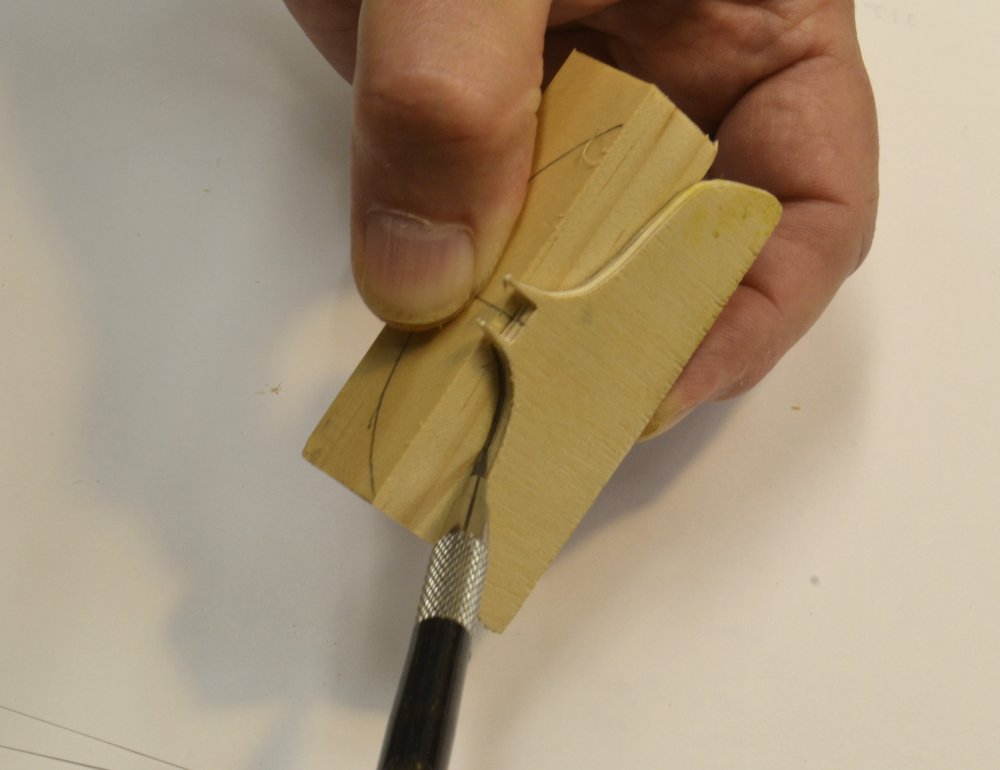
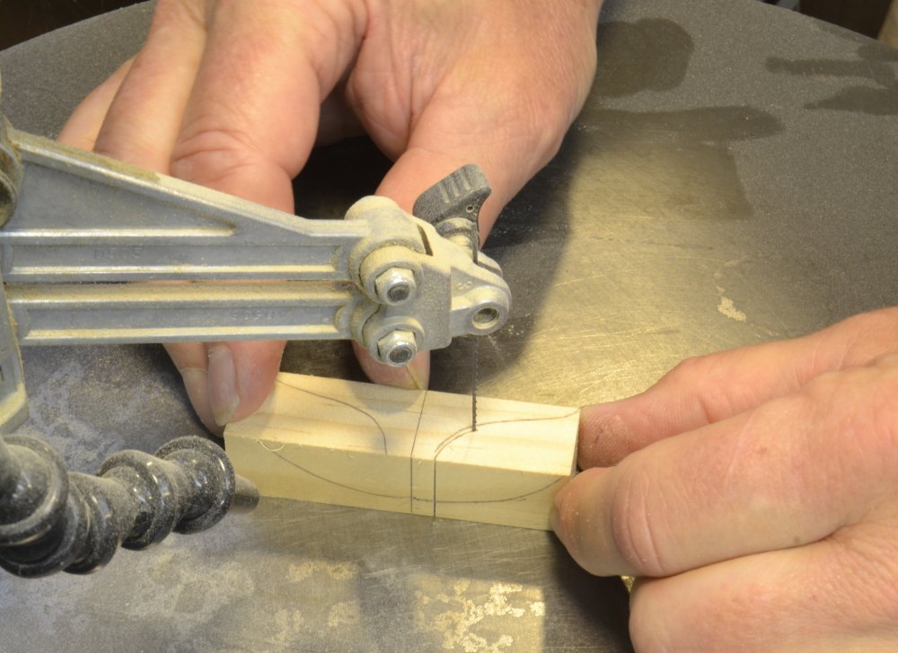
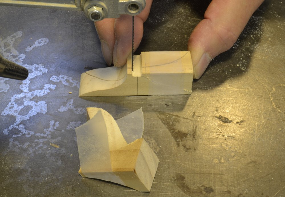
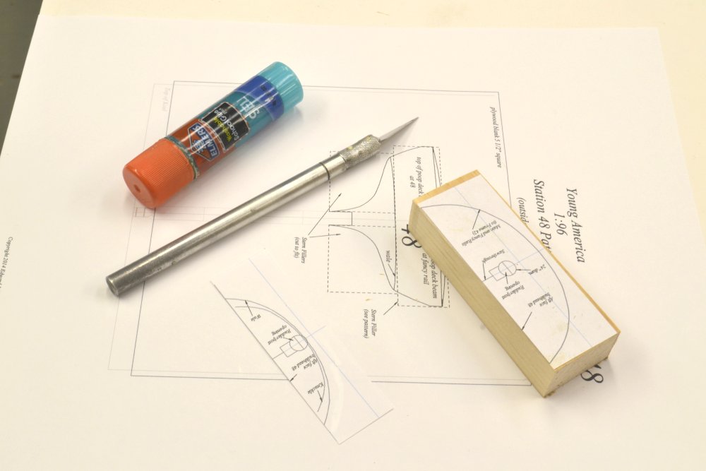
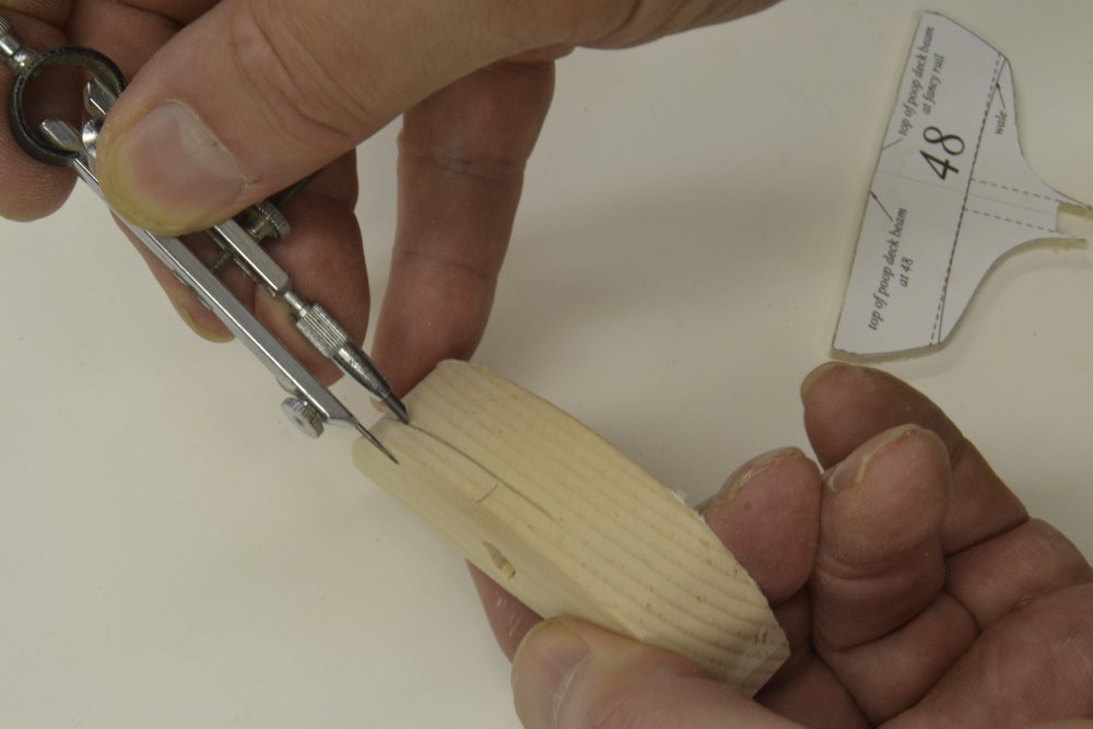
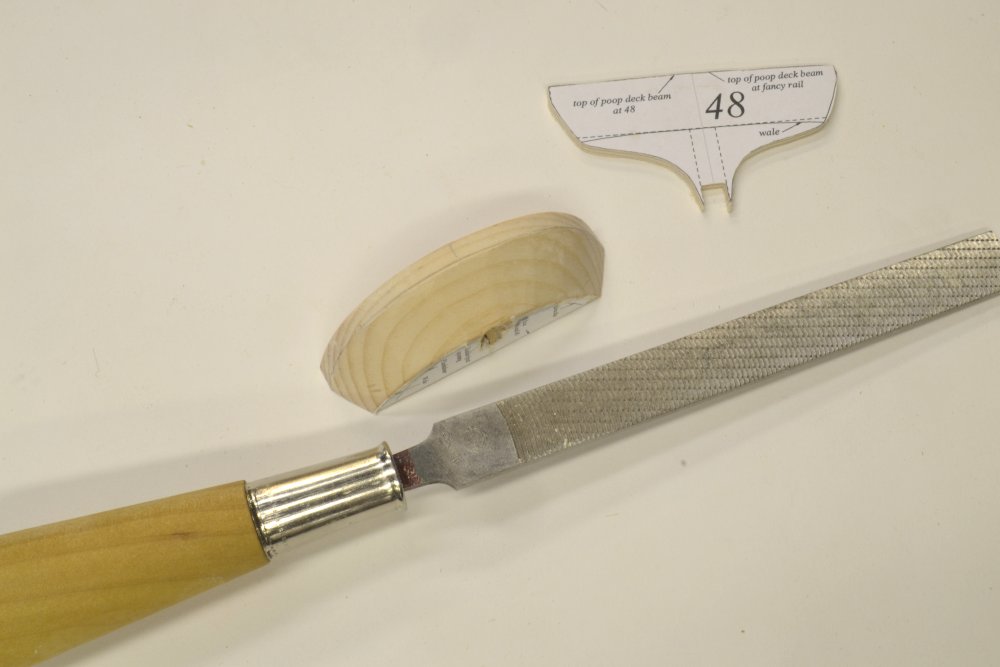
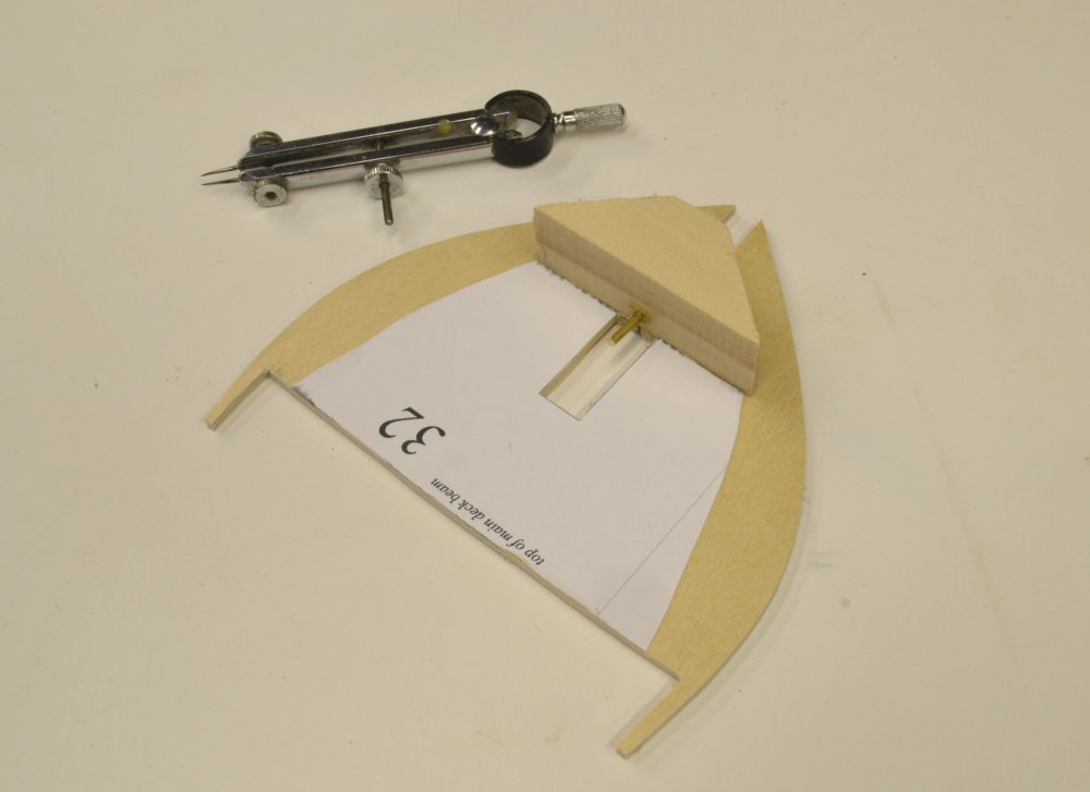
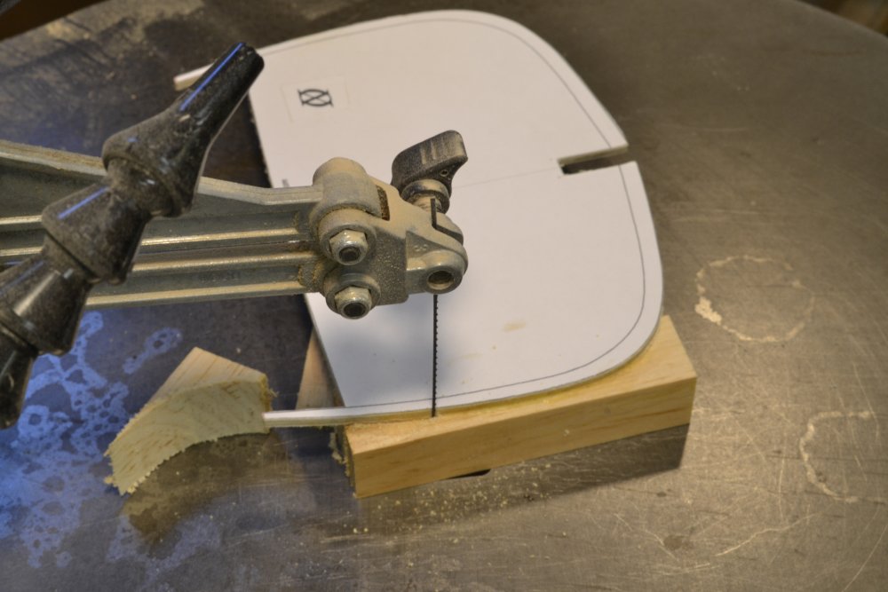
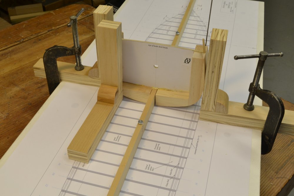
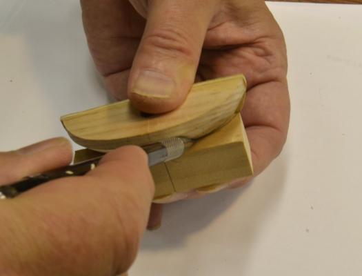
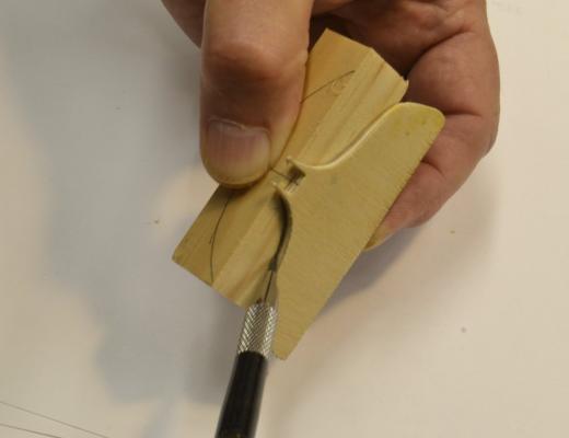
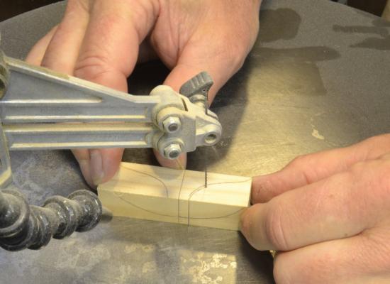
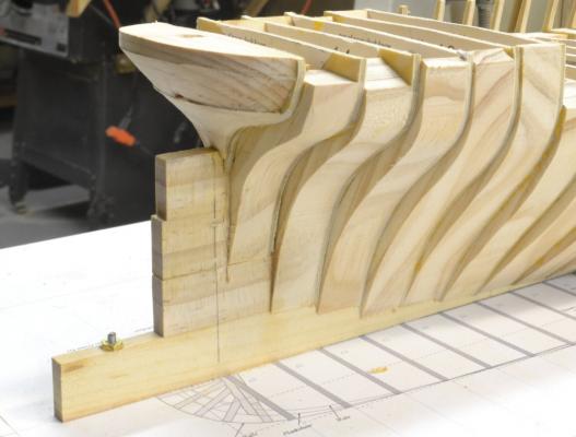
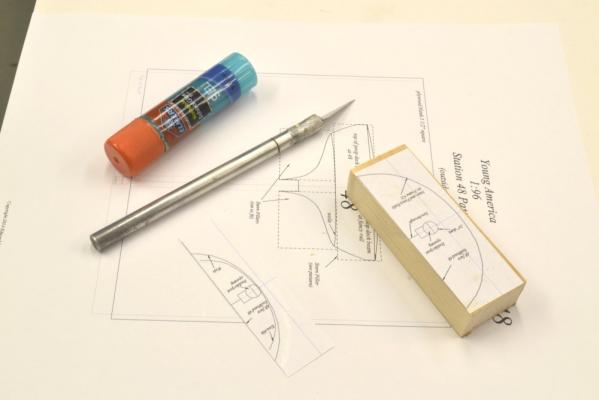
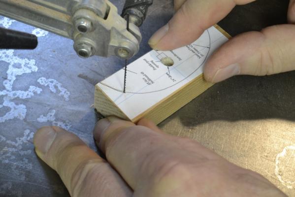
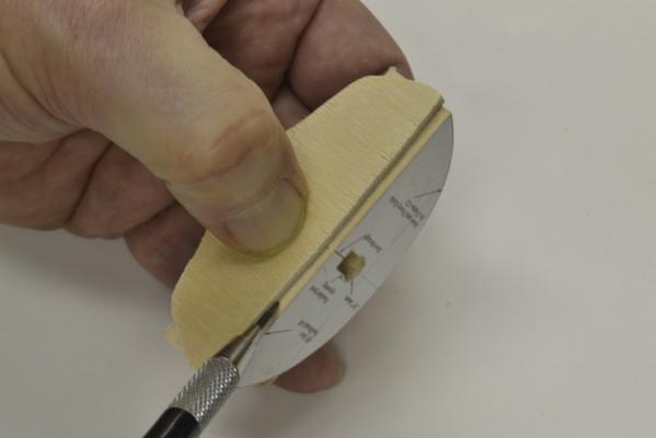
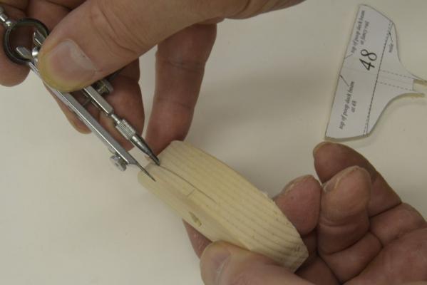
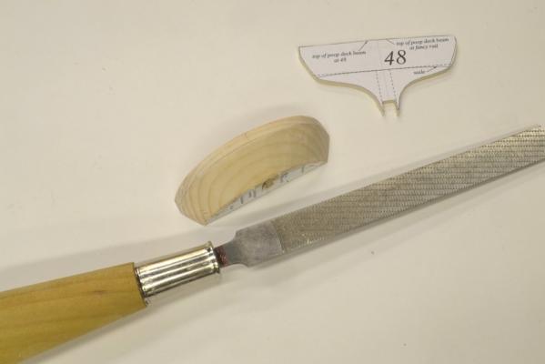
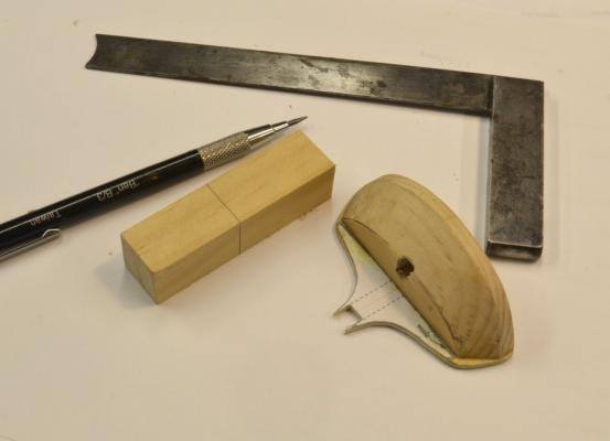
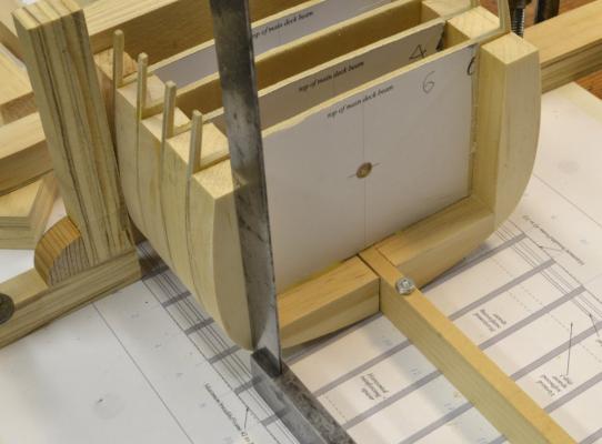
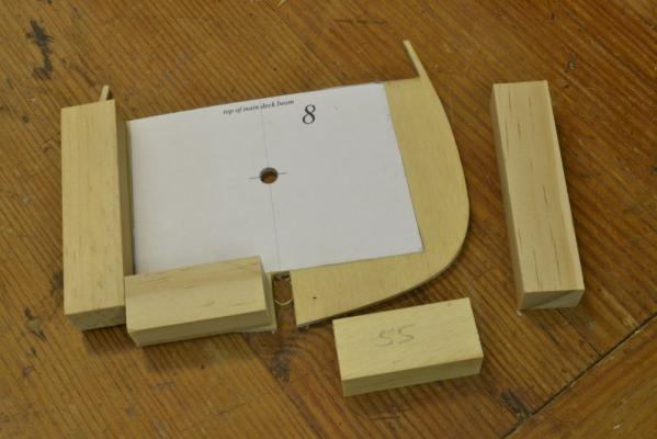
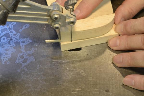
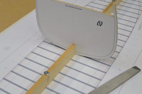
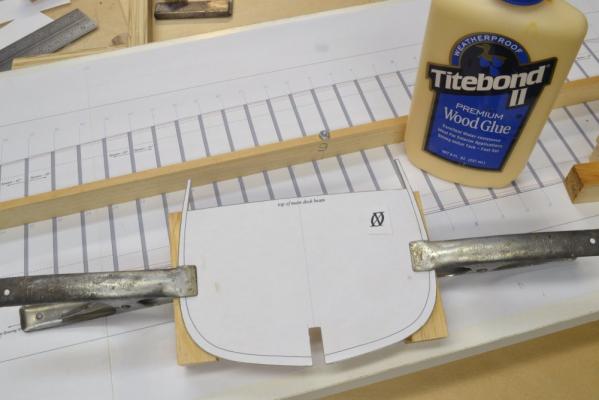
Young America 1853 – POB 1:96 Part 7 – Lower Stern In the framed version of the model, individual stern timbers provided the foundation for the planking of the stern. On this POB version the complex shape of the stern was constructed from solid pine. The upper section was shaped in the last part. The foundation for the stern below the wale was shaped from a solid block like the upper stern piece. The piece is curved in three planes. The horizontal curve of its upper face is defined by the lower edge of the upper stern piece – at about the line of the wale. In the first picture that line is being traced on a wood block. The piece was first marked with a centerline so it could be indexed to the stern assembly. In the next picture vertical curves on either side are being marked from the shape of bulkhead 48. With the lines drawn, the lower shape of the piece was cut on the scroll saw. The pieces removed were then taped back on using transparent tape so the curved line of the horizontal face could be cut as shown in the next picture. These cuts could be made in either order. The piece was then glued to the aft side of frame 48 and the upper piece. The frame 48 assembly was then glued to the hull as shown below. The curve of the aft face was then roughed out down to the forward edge of the sternpost – indicated by the pencil line on the spine. The pencil line shown was drawn using a template. This end of the hull is now ready for fairing – or will be when the excess spine material is removed. But first the bow will need to be constructed – in the next part. On this version of the model, all of the filling material – spacers, spine and these filler blocks – are cut from ¾” thick pine. This material is easy to obtain, can be ripped and cross cut on a 4” diameter model saw and on most scroll saws. I used available scraps for this – some clear sugar (white) pine and some pine from a home center. This latter material is actually a species called Radiata. While a form of pine and clear of knots, it has dark hard growth rings that can be seen in the spacers in the above picture. The contrast with the clear sugar pine of the lower spine is evident. In retrospect, I would avoid this species. The hard growth rings made some work more difficult, specifically pinning and tacking to secure planking, but also some shaping. Ed

- 191 replies
-
- 26
-

-
- young america
- clipper
- (and 1 more)
-
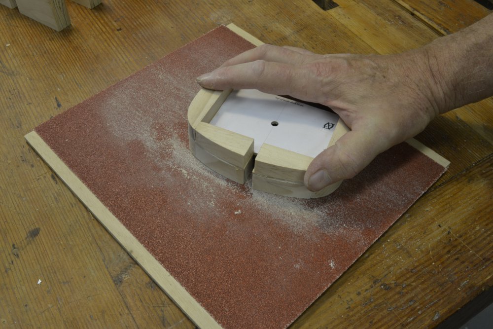
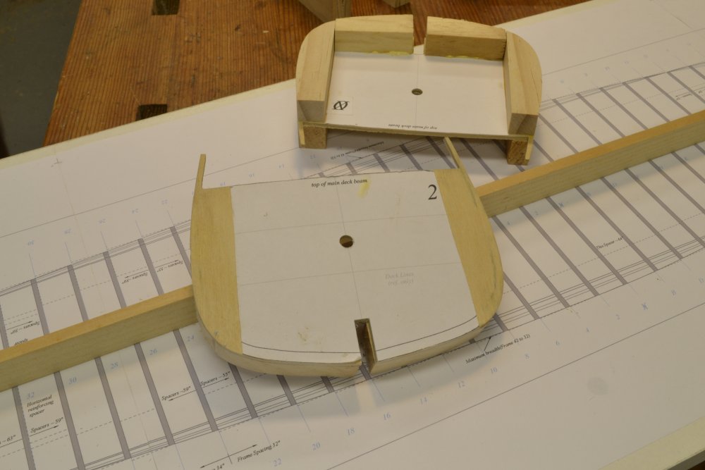
Young America 1853 – POB 1:96 Part 6 – Upper Stern After erecting all the “square frame” bulkheads, a foundation for the circular stern was fashioned from blocks of ¾” pine – one for the area above the wale and one for the lower section. First the upper piece. The first picture shows a piece of ¾” pine stock with a pattern for the top pasted on. The pattern for the underside of this piece as well as the pattern for bulkhead 48 showing the positioning of the blocks is shown. The circular (really elliptical) pattern line on the top of the block is the line of the fancy rail at the top of the framing. It is also the line of the main rail. The hull is vertical between these two lines at the stern. The curve of the lower side of this block – shown on the cut out bottom pattern – is roughly at the line of the wale. In the next picture both patterns have been aligned and attached and the line at the top is being cut on the scroll saw. Note that a hole for the helm port was bored through this piece. The key hole shape of this was cut out once the curve was cut. In the next picture the piece is held at its proper position on the aft side of bulkhead 48 and the curve of the deck at that point is being marked. Do to the shear of the decks, the top of the piece will be higher at the very stern. The top of the piece is next pared off to yield the correct shear and round up to provide the surface for deck planking. In the next picture this has been done and the line of the main rail is being marked out. The underside of the main rail is about 18” below the fancy rail line to allow two strakes of 6” plank and the 6” main rail to fill the space above the line. The area below this line is then cut back at an angle to the line on the underside pattern as shown in the next picture. Most of the wood removal was done on the disk sander, then refined using the rasp shown. In the next picture the piece has been glued to bulkhead 48 – after removal of part of the bulkhead pattern. Note that the stern piece is slightly smaller than the bulkhead. This is due to the curvature of the hull. The forward face of the bulkhead is on station 48. The aft edge will be faired back to its smaller line. The other block in this picture – marked with a center line - will be the lower stern piece. Next time. Ed
- 191 replies
-
- 29
-
-
- young america
- clipper
- (and 1 more)
-
I attach patterns to wood with ordinary Elmer's paste sticks - school glue. Patterns adhere very well and are easily removed by wetting then rubbing them off after a few seconds. Stick glue is water soluble so any residue is easily removed - and there is no annoying bottle brush to deal with. Ed
-
Thank you, Christian. A good suggestion. When the paint is gone the hull is shaped. Ed
- 191 replies
-
- 3
-
-
- young america
- clipper
- (and 1 more)
-
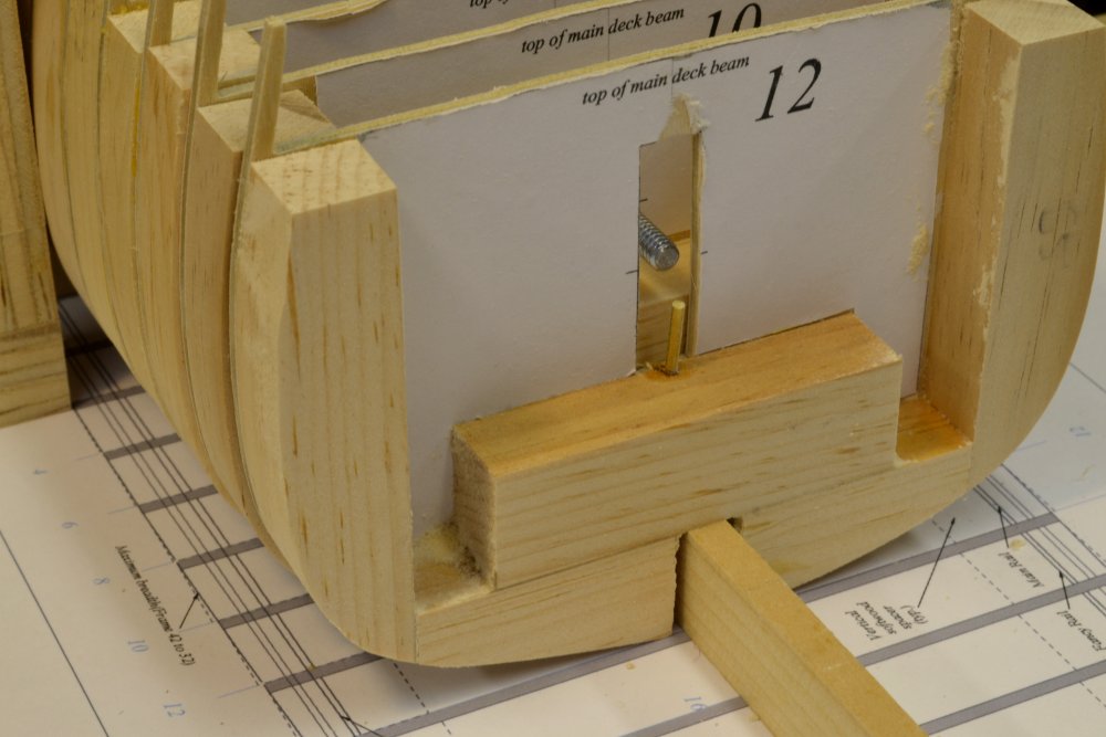
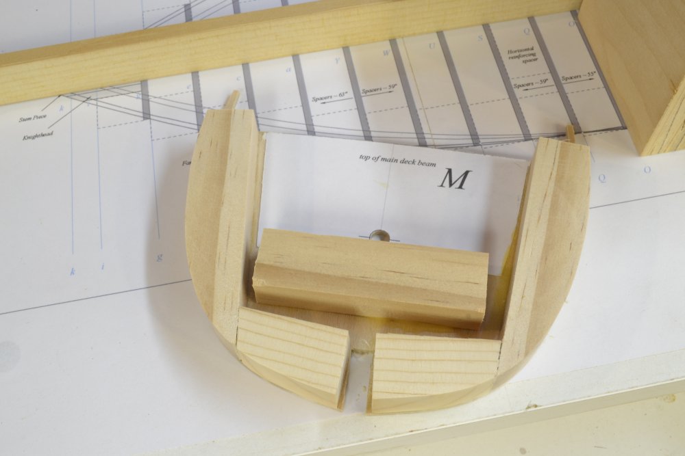
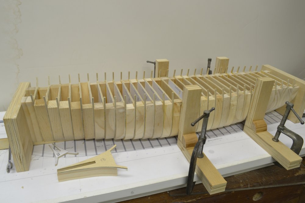
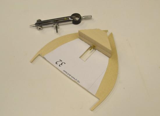
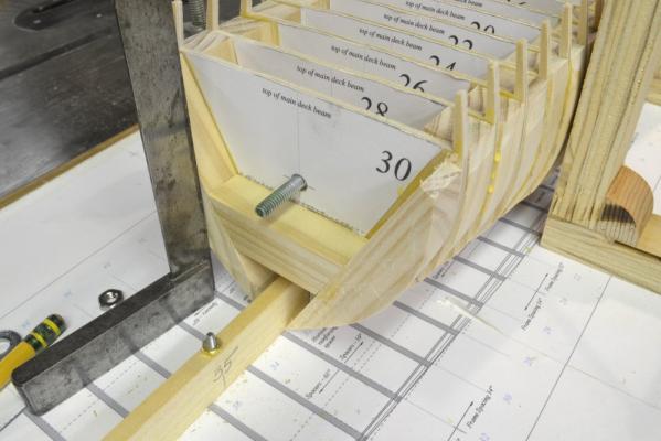
Young America 1853 – POB 1:96 Part 5 – Mast Steps As bulkheads and spacers are added, it is necessary to make provision for supporting the lower ends of the masts. On the framed model these steps are fully detailed and visible through the view ports, but on this version they need only be simple, functional and strong. The first picture shows the step of the main mast just aft of bulkhead 12 – looking forward. The brass pin will fit a hole in the bottom of the mast. The bulkhead has been cut out to provide clearance for the mast. A reinforcing spacer can just be seen through the opening. For strength, the plywood bulkheads on either side of each mast are sandwiched between such reinforcements. The next picture shows the reinforcing spacer glued to the plywood bulkhead aft of the foremast. The step of the mizzen mast is shown below before being installed. The holes for the brass pins need to be precisely located, hence the dividers. The drawings show these locations at the height of the spacer blocks. The pins are slightly raked – roughly matching the mast rake. The next picture shows the bulkhead forward of the one above, with the reinforcing spacer in place. The next picture shows the hull framing well advanced. The squares clamped to the shipway are important. They keep the hull plumbed to prevent twisting as new bulkheads are added. The last picture shows the hull framed back to bulkhead 42. At the ends, the central spine needs to be built up with additional tiers to form the deadwood as the hull narrows. Also, in this picture, additional spacers have been inserted inside the outer ones to maintain a solid hull surface where the lines converge sharply at the stern. The complex rounded stern will be constructed in the next part. Ed


- 191 replies
-
- 32
-
-
- young america
- clipper
- (and 1 more)
-
THE 74-GUN SHIP by Jeronimo
EdT replied to Jeronimo's topic in - Build logs for subjects built 1751 - 1800
Good luck with your new project, Karl. Looks like you are off to a good start. Ed -
Lovely work, as always, Sherry. Very impressive lanterns. Ed
-
Addendum 6 - The Naiad Frigate Volume I - Jogging Cant Frame 26f This issue was brought to my attention by Albert, whose beautiful work on his model of Naiad can be found on this site. The issue concerns the accurate framing of the aftermost 9-pounder gun ports on the quarterdeck. These ports - one on each side - fall within the toptimbers of the aft cant frames. To frame these accurately requires "field fitting" the upper futtocks on frames 26f by jogging them slightly. Although jogging notes are included on all of the square frame patterns, the cant frame pattern in question does not include this. The attached pdf describes the required adjustment to frame 26f. Addendum 6 PDF.pdf Ed
-
Thank you for all the likes, and thank you, Frank, for the question. Once the threaded stud bolts are screwed into the hull - into the spine in this case because the keel assembly has not yet been installed on this model - the model is secured from under the base with nuts. Without lateral support the hull is vulnerable to damage from side thrusts - especially after the keel is installed. During hull construction, I normally support the sides with the squares clamped on either side of the shipway to prevent the hull rocking side-to-side. Later, when permanently mounting the model some other form of permanent lateral support will be built into the base. These will be lower on the hull but also designed to prevent rocking. Supports may also be fitted before rigging. Below is a picture of Naiad on her permanent base showing the supports used in this case. the support is very solid. Ed
- 191 replies
-
- 24
-
-
- young america
- clipper
- (and 1 more)
-
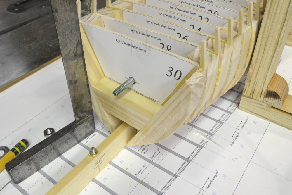
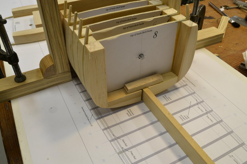
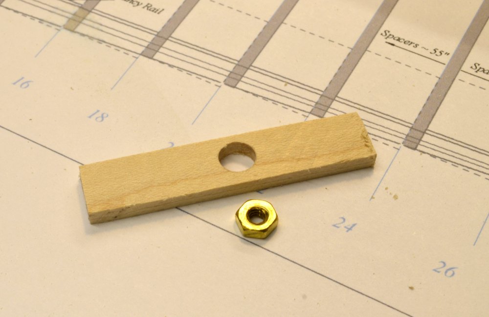
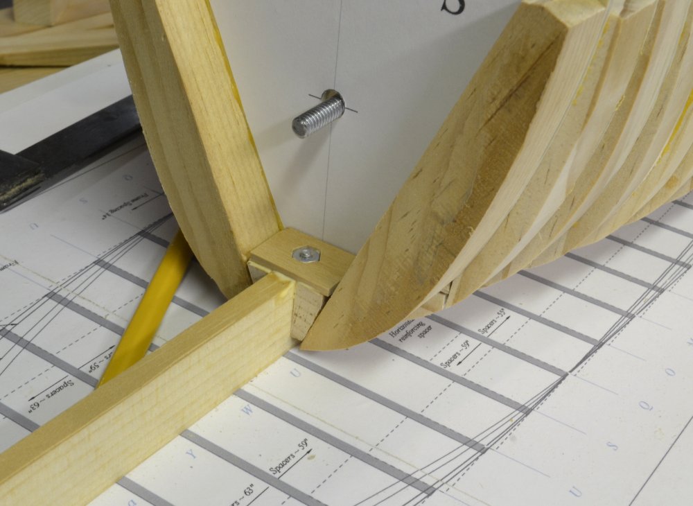
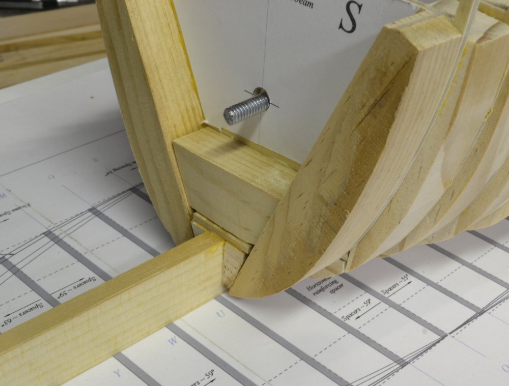
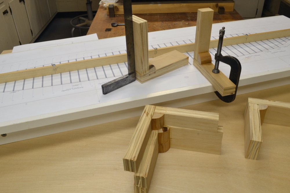
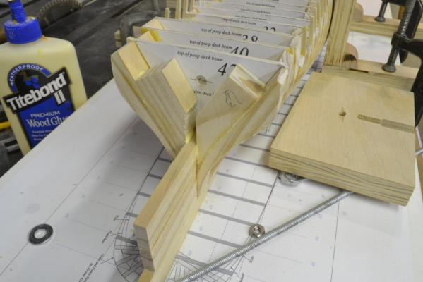
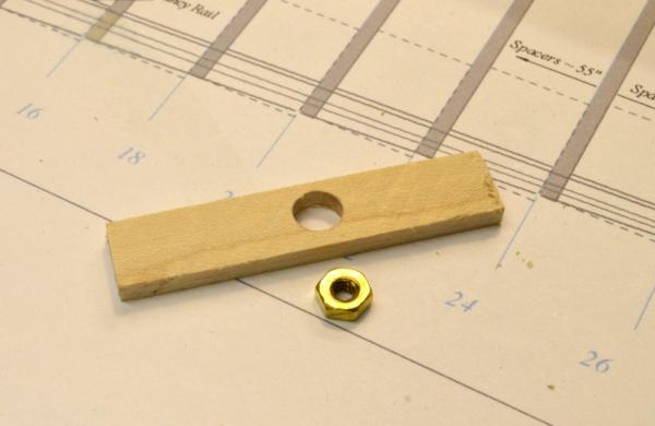
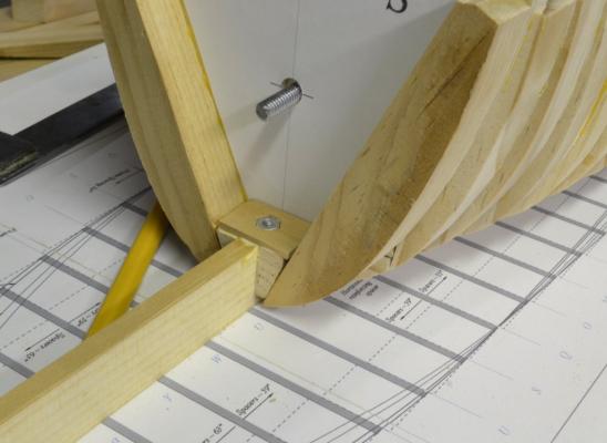
Young America 1853 – POB 1:96 Part 4 – Hold down bolts Some additional structural work needs to be done as the bulkhead erection proceeds. Nuts for hold down bolts need to be permanently embedded in the structure at three locations. These were set out on the drawings on odd-numbered frame lines so they would fall midway between plywood bulkheads which are set only at the stations – the even numbered frame lines. The spine and shipway were drilled at these locations earlier and threaded rods installed as shown below. The bolt in this picture is on frame line 9. The picture was taken before bulkhead 8 was installed (and before the numbers on the patterns were moved toward the center). The next picture shows this nut encased. The nut is encased in the lower of the two hardwood strips glued to the top of the horizontal spacers. The lower strip is shown in the next picture, before the hole was filed to fit the nut. The next picture shows the forward bolt at frame T being encased. In this case tow triangular blocks were glued to the spine and the strip encasing the nut is glued to it. In the next picture the assembly is capped with another fitted block. Although each of the three installations of these is slightly different, in every case there is a cap to hold in the nut and to act as a stop when the stud bolt is threaded in. All the parts are glued to the plywood as well as the side spacers, the assemblies are very strong. Next the mast steps. Ed


- 191 replies
-
- 23
-
-
- young america
- clipper
- (and 1 more)
-
HMS Naiad 1797 by albert - FINISHED - 1/48
EdT replied to albert's topic in - Build logs for subjects built 1751 - 1800
Just catching up with your progress Albert. Looking wonderful. Ed -
Hi Bruce, Sometimes its best not to count things. I look forward to your pics. Thanks for your comments - looking forward to resuming work on the framed model. Trying to get the POB version caught up. Ed
- 3,618 replies
-
- 2
-
-
- young america
- clipper
- (and 1 more)
-
Thank you all for the comments and likes. Let me try to address the points raised. First, the method was developed to provide a learning experience erecting hull frames as is done on upright full framed models - like Naiad, Young America and others - but with simpler bulkhead construction. I view this as an early step on the full framed learning curve for beginning scratchbuilders that want to try those more advanced models at some point - but want to work up to it. Frame alignment - in my experience - is one of the main challenges in full framed upright modeling. For this reason these methods and this model will be included in the forthcoming Young America book. Having said that, I believe this is, on its own merits, a very good way to construct a very accurate, strong (very strong) POB hull. To answer your concern, Mike. Shrinkage is not an issue if seasoned wood - ideally sugar pine - is used for the spacers. First, the aircraft grade plywood bulkheads are very stable. The large glue surface between the pacers and the plywood very effectively resists shear stresses that might lead to twisting. Differential shrinkage over the length of the hull since last summer has opened just two small gaps of less than 1/32" between plywood and spacers. So the hull has gone through a full cycle of high to low to high humidity. Delaware Valley summer humidity is very high and last winter was very cold and dry. No deformation of the hull has occurred over this period. When added, planking should constrain any further movement. I was concerned about the effects of clamping when gluing - resulting in tighter joints at the top where normal clamps can be used. The location of the holes for the threaded rod were placed to maximize uniformity of pressure on the joints. The bulkheads are very parallel to each other. With the glue joints on the flats of the spacers, they are very much stronger than the end glued pieces fitted between bulkheads on many POB models. The biggest risk to hull twisting is mis-alignment when setting frames - just like on full framing. The key is to align every frame as it is installed and to keep the hull plumbed throughout the process. Clare, you might say this is similar to lift construction but with vertical lifts. In a sense this is true, But the large number of very accurately formed plywood bulkheads makes final shaping and fairing of the hull easy and extremely accurate as will be seen in later posts. It is true that there are similarities - as will be seen when the bow and stern are shaped. Any new approach carries risks. I love these questions, because they help - even if after the fact - test the validity of the process. Keep them coming. Ed
- 191 replies
-
- 21
-
-
- young america
- clipper
- (and 1 more)
-
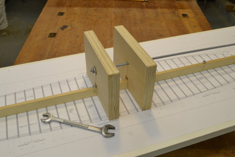
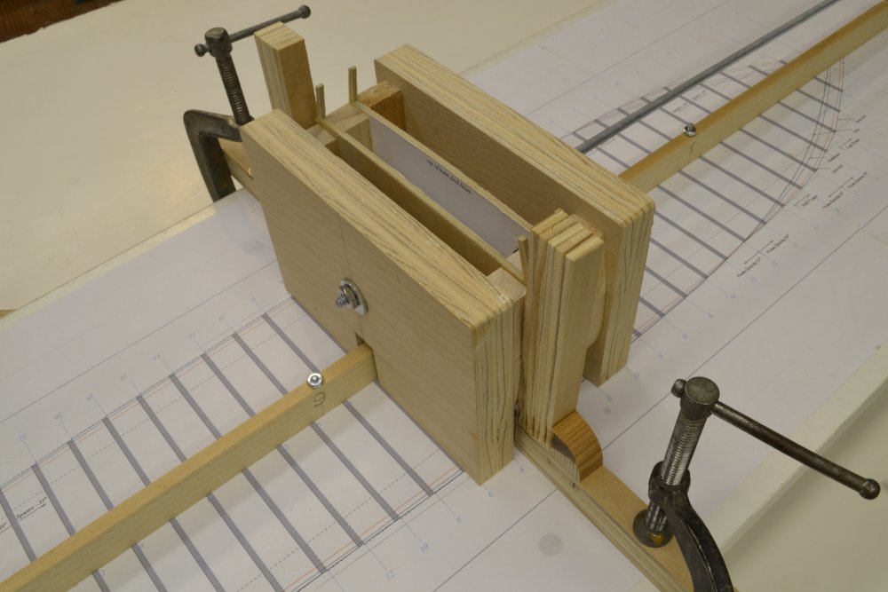
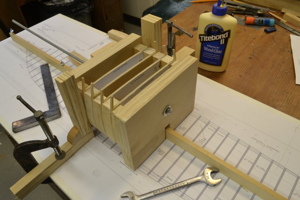
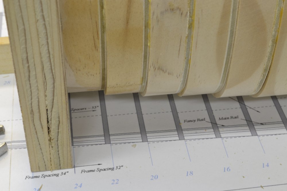
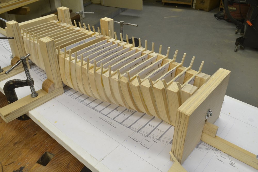
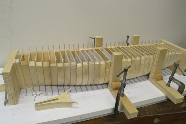
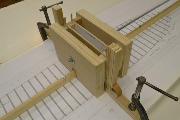
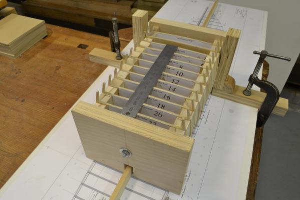
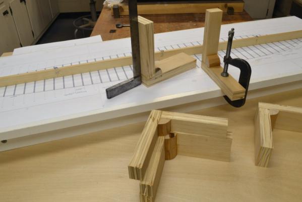
Young America 1853 – POB 1:96 Part 3 – Erecting Bulkhead Assemblies In the full-framed version of the model, frames were plumbed then clamped in place using small wood spacer blocks or later, using ribbands at the planksheer. For this model the bulkheads are glued to their neighbors using wood spacers. The method is basically the same but requires a different clamping method. The first picture shows the device used to clamp the bulkheads for gluing. The two plywood rectangles fit loosely over the central spine. They are drilled at the same level as the holes shown earlier in each bulkhead. A long, loose-fitting threaded rod is used to tighten the glue joints as each new bulkhead is added and aligned. The next picture shows bulkhead 2 being glued. The squares are used to align the frame to the maximum breadth line on the shipway plan. The nut on the threaded rod is then tightened to secure the glued joint. The next picture shows more bulkheads added - one at a time. And so on. In the above picture the fairness of the deck “beams” is being checked with the metal rule. If the notches over the spine are cut carefully, the line should be precisely fair. The next picture is a close up of some bulkheads showing the excess spacer material that will need to be removed later. Note that the station lines on the shipway plan align with the plywood bulkhead at its maximum breadth. When the hull is faired by removing the excess and smoothing the line to over the plywood sections, the hull shape will be precise. The last picture shows the framing of the forebody almost complete. Note in this picture that the midship frame and another forward of that are held in alignment throughout this process by squares clamped to the shipway. This prevents the hull shape from twisting as frames are added. While building up to this point, a number of special attachments were made on some of the bulkheads for mast steps, reinforcements and hold down bolts. I will show some of these in the next part. Ed


- 191 replies
-
- 32
-
-
- young america
- clipper
- (and 1 more)
-
Extraordinary work as always, Gaetan. Every aspect is beautifully executed. A further comment to Druxey's stairs observation: in my experience with French design, esthetique sometimes seems to outrank fonctionnel, but the results are often delightful Vive la France. ED
- 728 replies
-
- 6
-
-
- le fleuron
- 64 gun
- (and 1 more)
-
ROYAL CAROLINE 1749 by Doris - 1:40 - CARD
EdT replied to DORIS's topic in - Build logs for subjects built 1501 - 1750
Doris, I am glad your postings have returned. Thank you for the pictures and video of your completed model. I am speechless. The work is simply stunning - interiors, exteriors, rigging, carvings, finish, attention to minute detail.... I could go on. I especially loved the burl tabletops, the fretwork on the chair backs and the paintings. You have set an impossible standard for the rest of us mortals. Go, Doris! Ed- 883 replies
-
- 12
-
-
- royal caroline
- ship of the line
- (and 1 more)
-
The purpose of the holes in the bulkheads will be revealed in the next part. Ed
- 191 replies
-
- 2
-
-
- young america
- clipper
- (and 1 more)
-
Young America 1853 – POB 1:96 Part 2 In the last part, spacers were shown being glued to the midship bulkhead. The spacers were cut from ¾” thick pine, ripped to a width equal to the distance between stations (even numbered/lettered frame lines) and the 9” plywood thickness. These were then glued to the bulkheads in an arrangement as shown in the first picture – to provide a continuous hull surface for later planking. The spacers in this picture were cut to a width of 55” – marked on one of the loose pieces. Station spacing in this area is 64”. Subtracting the 9” plywood thickness leaves 55”. As mentioned before, 9” plywood was used because that is the siding of the integral toptimbers. The excess spacer material was removed by cutting along the bulkhead as shown below. This was then trimmed right to the line using a disk sander. The thickness of the glued assembly was then measured and if necessary adjusted and/or leveled by sanding as shown below. In this picture the midship bulkhead assembly is being sanded. It has spacers on both sides. The spacers are always sized at the broader of the two adjoining bulkheads, so bulkheads fore and aft of this one are smaller. All other bulkheads have spacers on only one side – the forward side on those forward of midship and the aft side on those aft of midship. Trimming the second bulkhead on this frame is shown in the next picture. The next picture shows the finished midship bulkhead trimmed to size with its adjacent partner – both ready to be erected. In the next picture the midship bulkhead is being erected on the spine. The alignment methods are virtually identical to those used on the fully-framed version – squares set at the maximum breadth line on both sides and additional squares to hold it vertical and on the station line. The only glue joint here is between the plywood and the spine. Additional bulkheads will add the strength as they are installed. This is very similar to the alignment of real frames at the original shipyards. Using this method on these simple assemblies is a step toward erecting authentic model frames on more advanced models. This was one of the purposes behind this process – and the entire bulkhead model. Erection of additional frames will be described in the next parts. Ed


- 191 replies
-
- 24
-
-
- young america
- clipper
- (and 1 more)
-
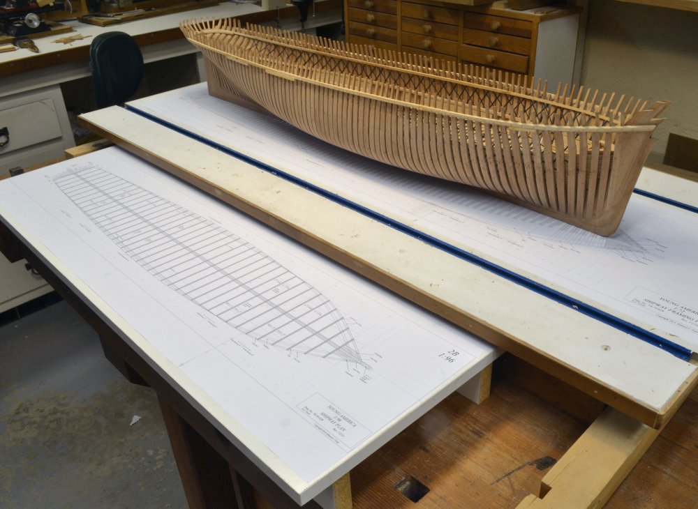
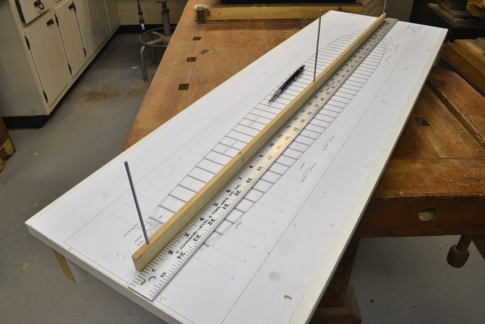
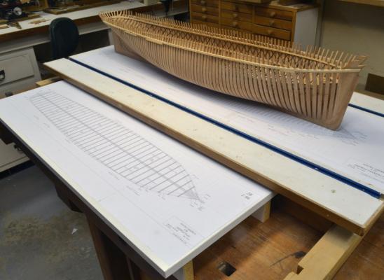
Young America 1853 – POB 1:96 Part 1 The 1:72 framed model of Young America will be on semi-hold for the next month or so, while I do further research and prepare drawings for the remaining work to complete the model. Since I have been working in parallel on a smaller 1:96 POB version of Young America, I decided to include some of that work in a separate build log. I do not yet know how far I will take this model. It has been built as a demonstration model for Volume I of the Young America book, which includes substantial information – text, pictures, drawings, patterns - for building this smaller, simpler model. I included this to address interests of beginning scratch builders and/or those not wanting to build the fully framed version. In developing methods for constructing this model, I wanted to think of this as a stairway on the learning curve to upright, framed modeling, like that used on Naiad, YA, Alfred, the popular Swan Class types, and others featured on this site. Although the hull framing for the POB model is much simpler, the methods described for setting and aligning bulkheads are very similar to those used on the larger framed version – and like those used in the real shipyards. These methods differ somewhat from common forms of POB modeling. I hope this different approach will be of value to some modelers. Like my other build logs, this will be an overview of progress and general description of methods - not a detailed tutorial. I leave that to the book. So, with that introduction, I will start with some preparations. The first picture shows the model shipway constructed for the POB model – next to the larger version. This photo was taken last November, shortly after deciding to incorporate a POB version in the book. The shipway is much simpler – no T-tracks and made from a melamine coated particle board shelf. The shipway plan is also simpler and geared to setting bulkheads instead of square, half and cant frames. The next picture shows the “spine” on which the bulkhead assemblies will be set. Stud bolts are being installed that will attach it to the shipway and later serve as hold-down bolts. The spine is not a keel and does not replace the keel. A fully detailed keel assembly will be fit under this later. This is merely a device on which to align bulkheads. It is thick enough for that purpose and initially extends well beyond the hull. The next picture shows the spine bolted down and the studs trimmed to size. The picture also shows simple, homemade squares that can be clamped to the shipway as shown. The next picture shows the midship bulkhead set on the spine. The bulkhead is cut from 3/32”, aircraft grade plywood, from the pattern shown. The pattern is an early version – note the pasted-on ID. Other detail was later added to the final patterns. The bulkhead includes the toptimbers. These were sided 9” (3/32” at 1:96). The high quality plywood will allow these to be finish sanded and painted, eliminating the need for separate toptimbers. Pine spacers, cut from ¾” stock, provide the primary strength in the hull assembly. These are cut to widths that match the spacing between bulkheads. In the next picture two of these are being fitted to the midship bulkhead. Most frames have four of these that fill the space between the plywood bulkheads. When faired to the outsides of the bulkheads, the spacers will provide a smooth, flat planking surface as well as great strength to the assembly. More on these spacers in the next part. Ed

- 191 replies
-
- 29
-
-
- young america
- clipper
- (and 1 more)
-
As always, I appreciate all of the comments so many have made on the Young America project. I am sorry that it has been well over a month since the last progress report. The model work has been on hold for a few reasons - work on the book manuscript, a two week vacation from which we just returned, and the need to do research and drawings for the next phases of the build - fitting out the main deck, masting and rigging. I do not expect that there will be much progress on the model until later in the summer. However, during that period I will be posting progress on the 1:96 POB version of the model that has been constructed for demonstration purposes - to support the POB modeling processes that are also described in the book. Some may find this model and its contrasts with the 1:72 framed model interesting. I will start a separate build log for this. Since that model has progressed to the point shown in one of the above posts, the build log will be somewhat retrospective, but I will continue it as far as I decide to take that model. My intent with the smaller, simpler model has always been to take it to a point where remaining work on both versions can proceed from the same process descriptions. That has been done and the final chapters in Volume I of the book apply to both versions. However, I am considering continuing the POB build to a more finished state. Again, thanks to everyone for the continued support and comments. Ed
- 3,618 replies
-
- 16
-
-
- young america
- clipper
- (and 1 more)
-
sfm Good luck with your Red Jacket project. Bill's plans, I have three, are excellent. Sorry there have been no YA updates recently - too busy getting the book out. Ed
- 3,618 replies
-
- 2
-
-
- young america
- clipper
- (and 1 more)
-
Bravo, Mark! Ed
-
William L. Crothers I am very sorry to report that Bill Crothers passed away on Friday, May 1. He was in his 103rd year. Bill’s research and writings on American clippers and packets, in particular his intensive exploration of the structures of these ships, place him at the forefront of contributors to our knowledge of these subjects. I am personally indebted to him, for without his work there would be no framed Young America model, nor perhaps more excellent examples to follow. It was my special privilege to have briefly known Bill and to have his valuable comments on my work. I will always value the interest he showed in the model, no less than the writings that made it possible. Ed
- 3,618 replies
-
- 26
-
-
- young america
- clipper
- (and 1 more)
-
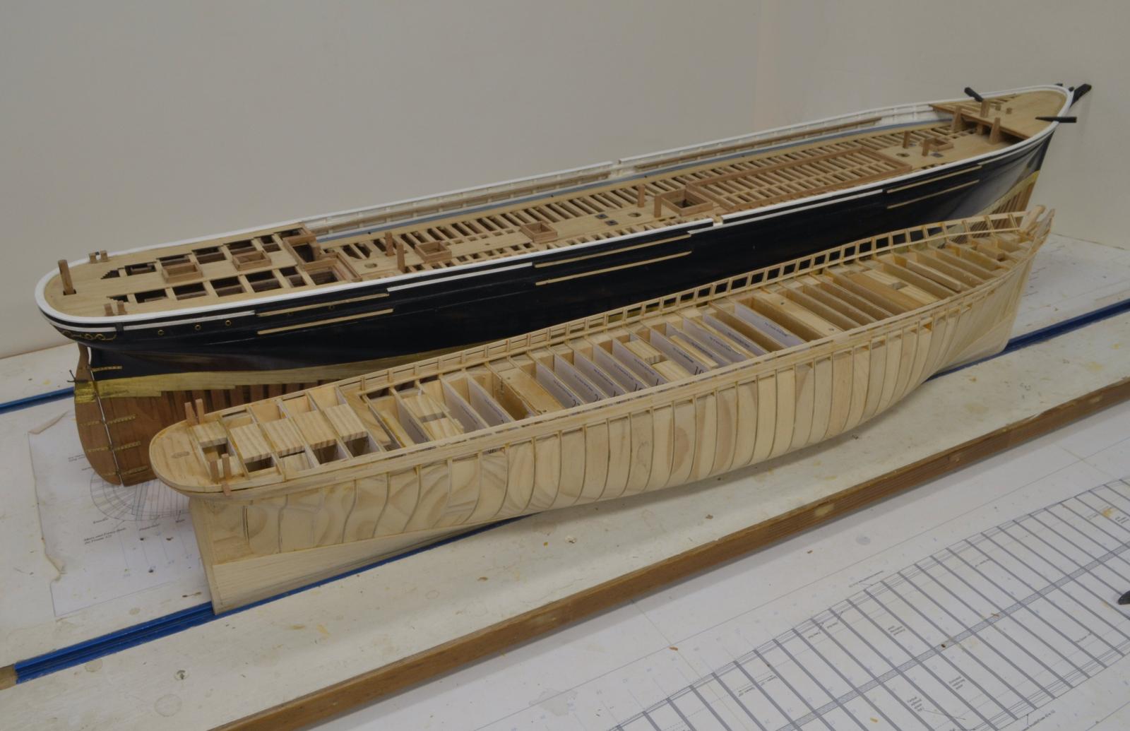
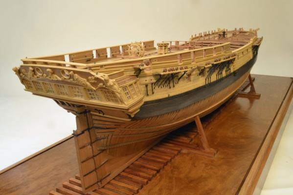
Thanks, everyone. I appreciate the comments and "likes" To answer your question, Greg, the 1:96 POB model has not reached the state of the framed model. The picture below was taken a few days ago. You are correct. At a point after completion of the framing and deck structural work, the two models converged so virtually the same methods may be used on both to complete them. You will note in the picture that bottom planking on the POB version has begun. There is no bottom planking on the framed version. The POB model was built from the beginning using similar methods to the framed model - such as upright construction, similar frame alignment methods - but from different drawings. Ed

- 3,618 replies
-
- 44
-
-
- young america
- clipper
- (and 1 more)