HOLIDAY DONATION DRIVE - SUPPORT MSW - DO YOUR PART TO KEEP THIS GREAT FORUM GOING!
×


EdT
-
Posts
2,213 -
Joined
-
Last visited
Content Type
Profiles
Forums
Gallery
Events
Everything posted by EdT
-
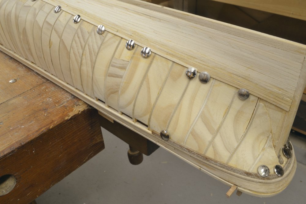
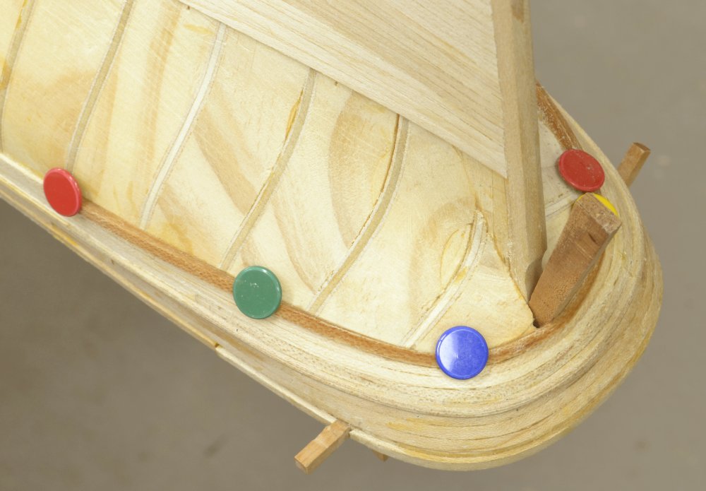
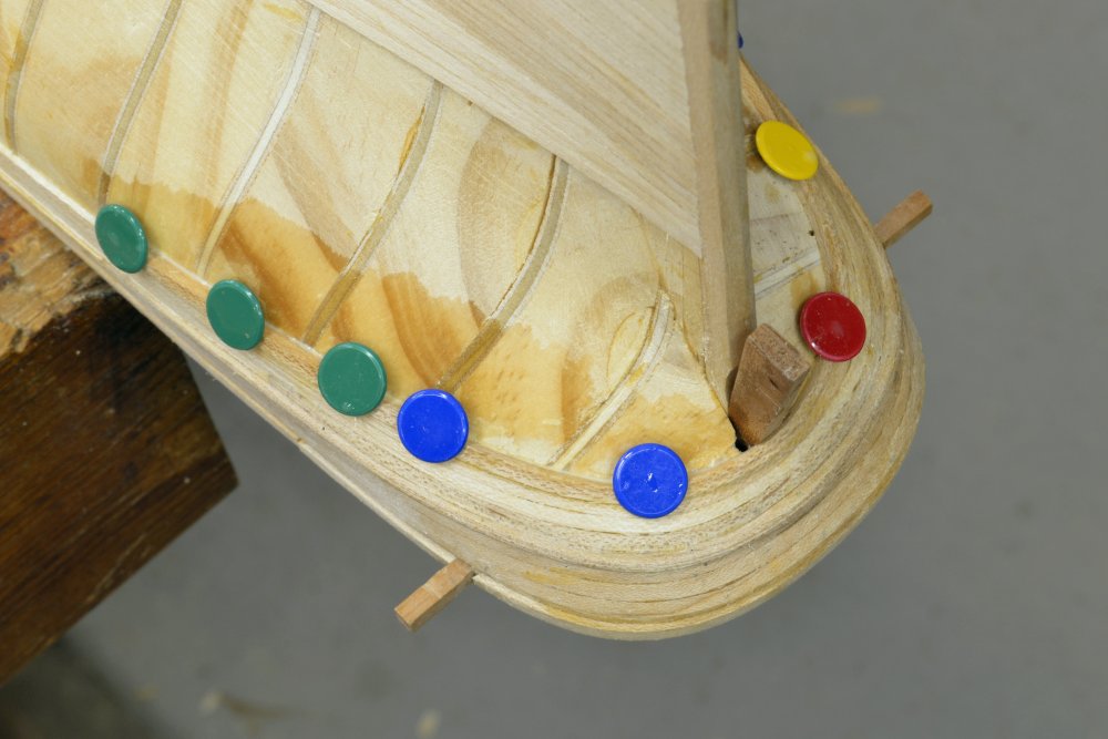
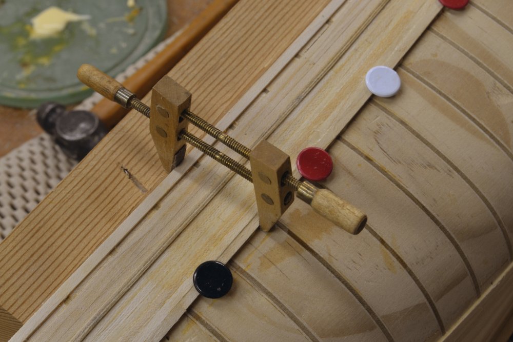
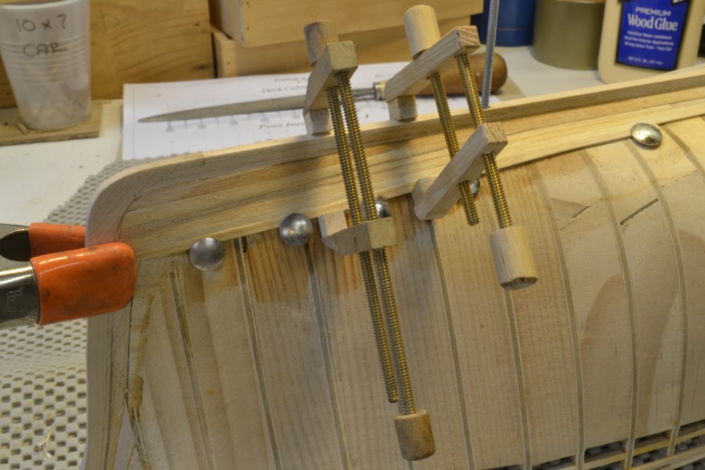
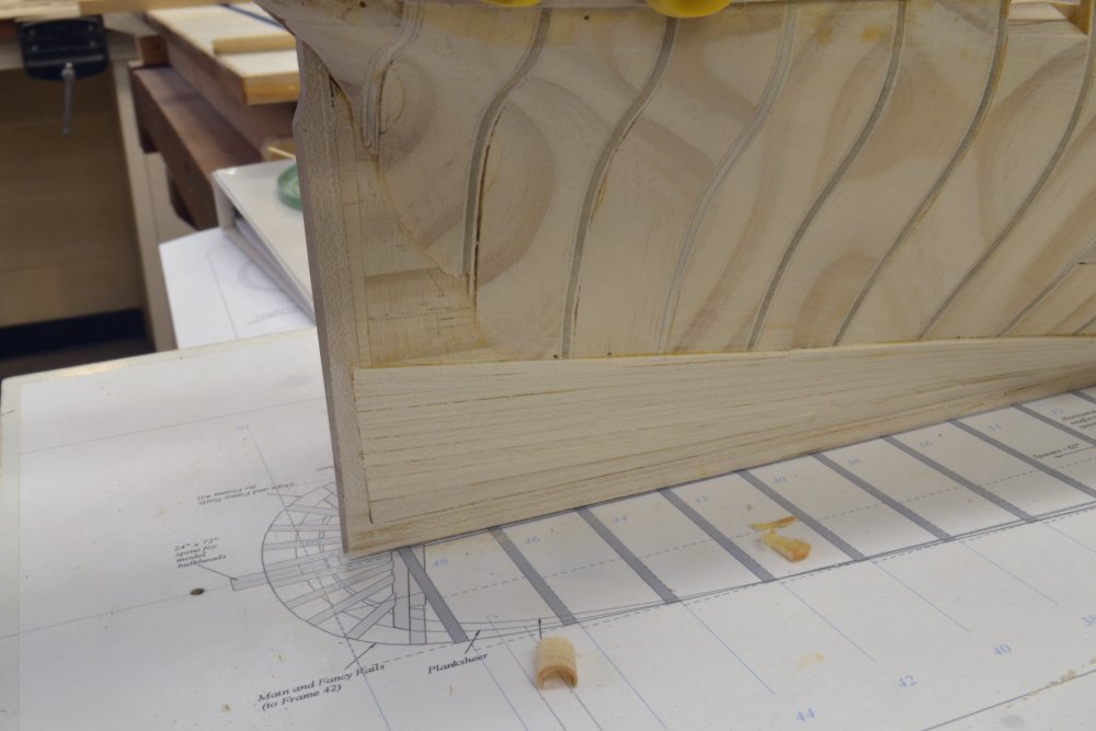
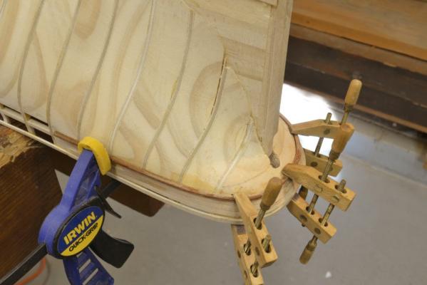
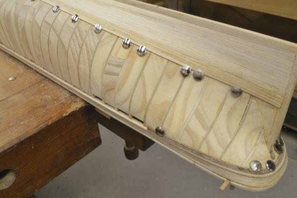
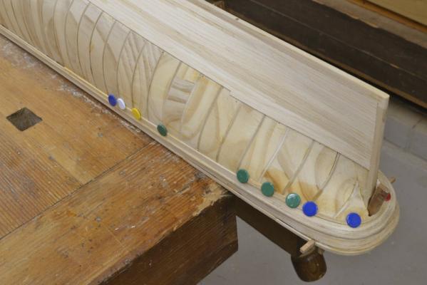
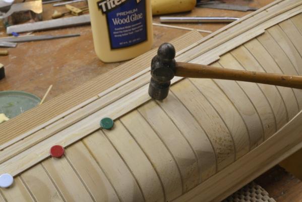
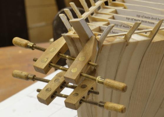
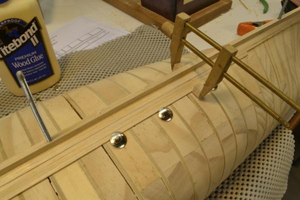
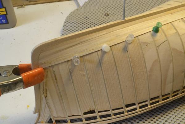
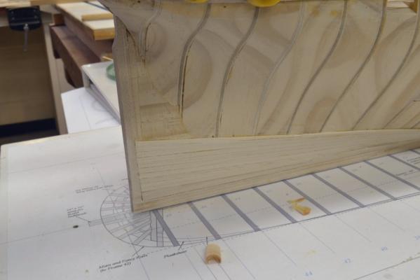
Young America 1853 – POB 1:96 Part 25 – Hull Planking The next task on the model was the hull planking. As with the topside planking, it began with the curved strakes around the stern. In the first picture the planksheer rail has been scraped to its profile, boiled for an hour or so and clamped in position around the stern. Screw clamps were used for this piece. It is not only curved around the stern but also twisted to be horizontal and not tilt downward. Straight-grained maple was used for all the bottom planking. Its flecked grain will be hidden by paint and metal sheathing. You will note in this picture that the topside planking above the planksheer was not yet installed. This would, of course, be installed before extending the rail forward. In the next picture that rail has been allowed to dry and then glued in place and the next strake has been boiled and clamped for drying. The strake shown above is also highly twisted to conform to the almost horizontal counter at this point. When planks are boiled it is essential that they dry thoroughly and shrink back to normal size. Premature gluing will result in shrinkage gaps between strakes. Waiting for these boiled strakes to dry is time consuming, so other work was done in parallel as shown in the next picture. In the above picture the planking is proceeding up from the bottom in parallel with the work at the stern counter. The next picture shows the fourth and final curved stern plank clamped and tacked in placed for drying. The thumb tacks and the wedge against the sternpost serve to keep this strake tight against its neighbors. In the picture the strakes above have been trimmed by sanding - after drying and before gluing to fit up tightly with the previous planks. They were slightly oversized initially to allow for this final fitting. In the next picture this fourth strake is being glued in. The hull is wet from washing off excess glue. The thumbtacks used here have plastic coated heads and are the preferred type. The plastic helps cushion them and reduces damage to the planks. The plastic also prevents wood discoloration caused by wetting uncoated metal heads. The next picture – taken at the same time – shows the progress of lower planking. To keep the plank in fair lines, stealers (dropped strakes) were used as needed. Some of the process for this will be shown in the next post. It is thoroughly described in the book. The next picture shows straight planking below the planksheer rail being glued down. The solid soft pine hull allows hammering down of the tacks – making pinning down easy. In the next picture a screw clamp is being used to close the gap between strakes. This can only be done where there is something for the clamp to grip – in this case the top of the side. In the next part the remaining planking on this side will be described. Ed


- 191 replies
-
- 23
-

-
- young america
- clipper
- (and 1 more)
-
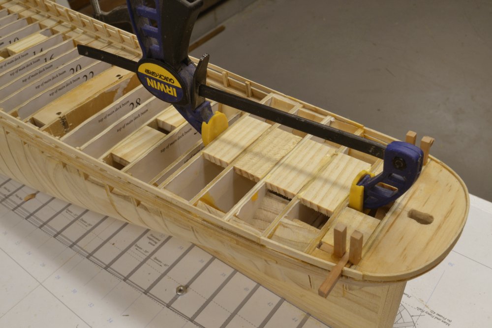
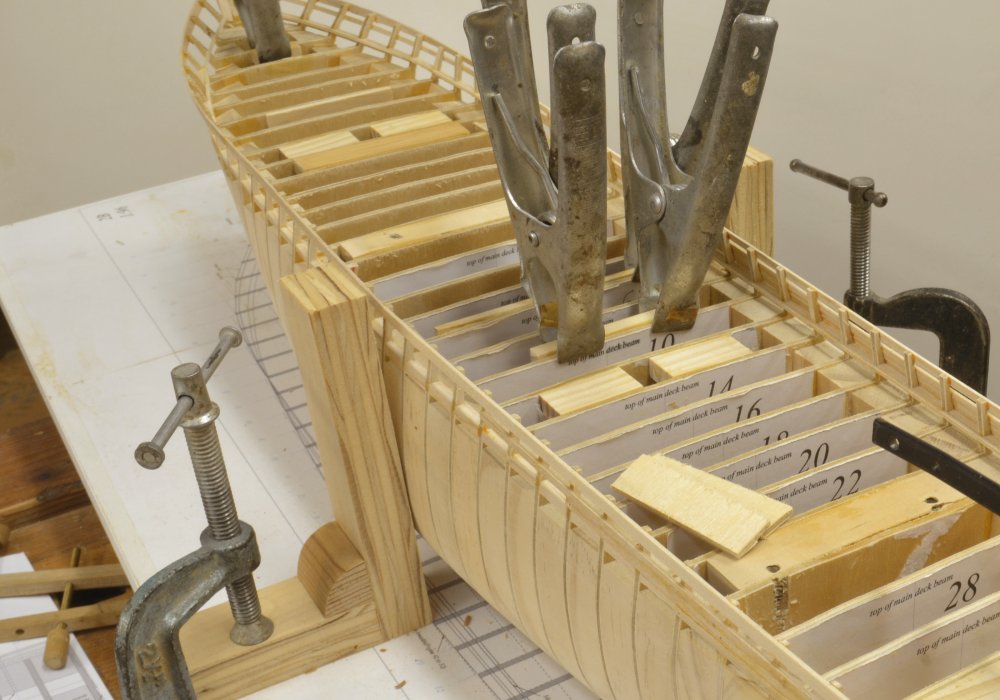
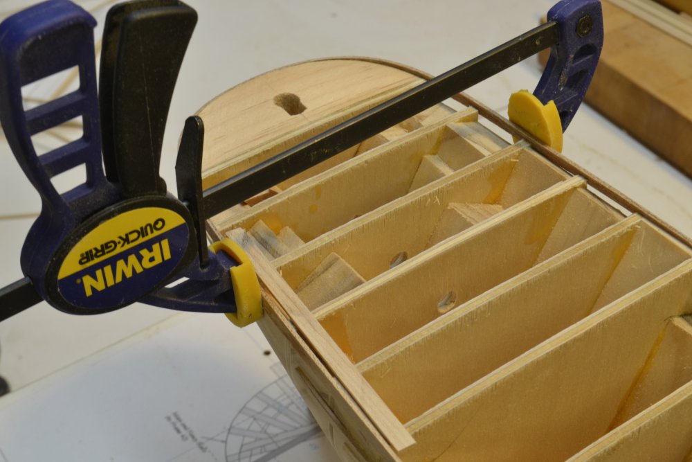
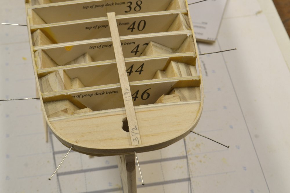
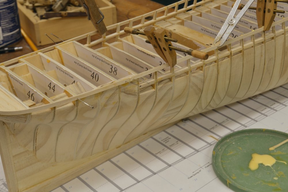
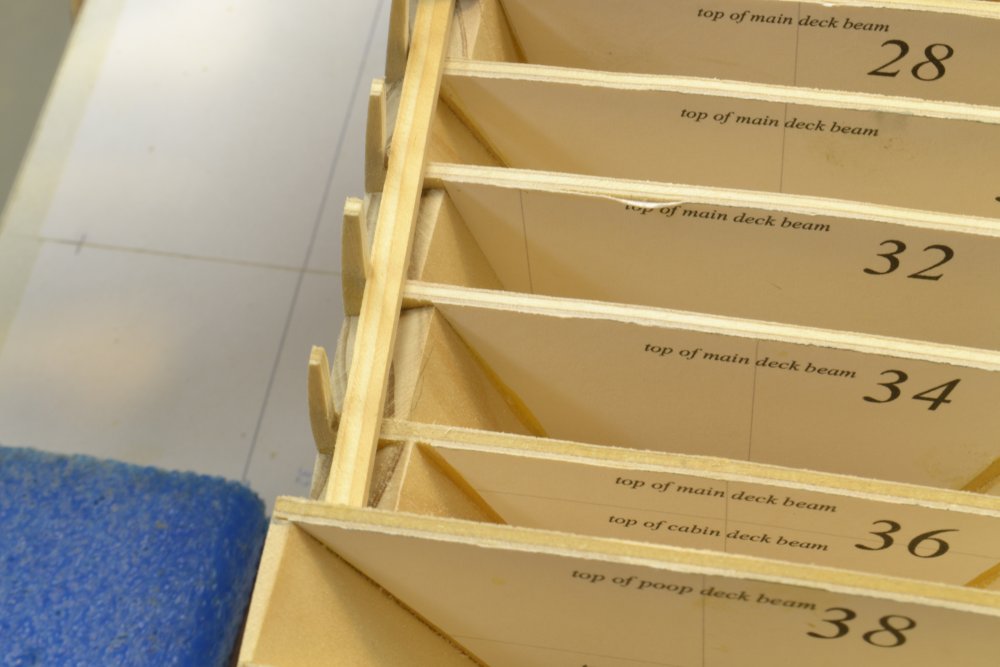
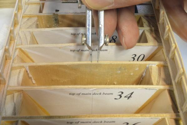
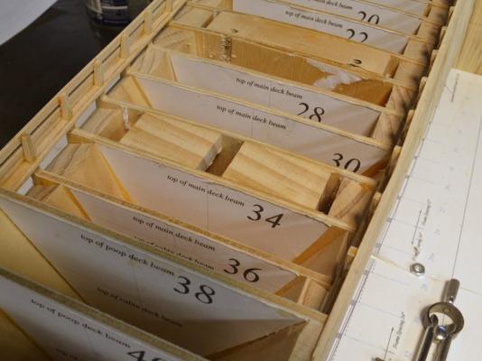
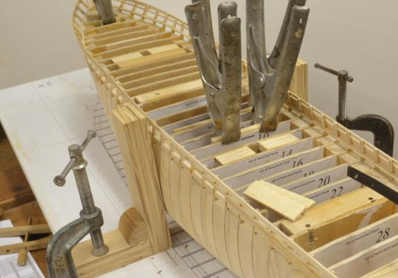
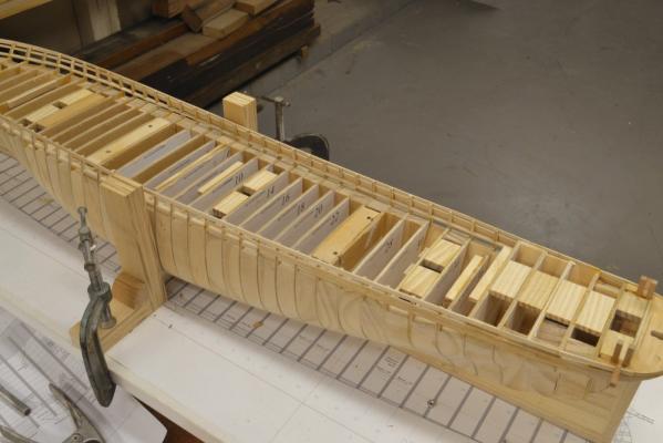
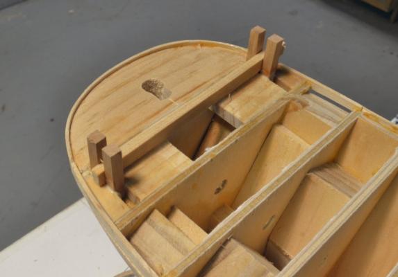
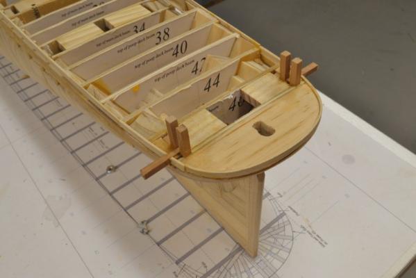
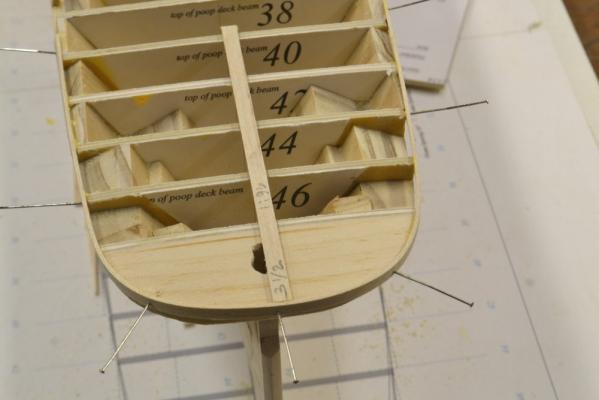
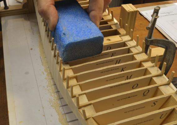
Young America 1853 – POB 1:96 Part 24 – Main Deck Structural Work The simplified POB model leaves open spaces in the deck structure that on the framed model is filled with intermediate beams, carlings, headers and ledges. These provide under-deck support for the various main deck facilities. Support for these facilities – cabins, hatchways, mast partners and the like – had to be added to the structure of plywood bulkheads before planking the decks. These supports will be invisible in the finished model, so they are made from simple pine chocks glued to the bulkheads. In the first picture the spacing for the main mast partners are being measured out from the centerline. In the next picture pine chocks have been fitted and glued between bulkheads to give lateral support to the mast. In the next picture a virtual platform of pine chocks is being glued between bulkheads to support the poop deck facitites – the coach, the two skylights and the helm housing. The mizzen mast supports can also be seen in this picture. In the next picture a thick pine strip is being glued to bulkhead 10 to support the aft head ledge of the main deck cabin. Clamping is important when installing these to ensure good glue joints. Aligning the grain of the pine pieces with the bulkheads is also important to avoid weak end-grain joints that will open up later. The last picture shows the model with all the necessary supports installed. To avoid missing any of these, all necessary supports were put on the hull structural drawings. With all this crude structure in place, the deck was given a final sanding to fair the lines of the bulkheads and also to make the pine chocks conform to the deck round up. With this necessary but dull work out of the way, I returned to hull planking. Ed

- 191 replies
-
- 26
-
-
- young america
- clipper
- (and 1 more)
-
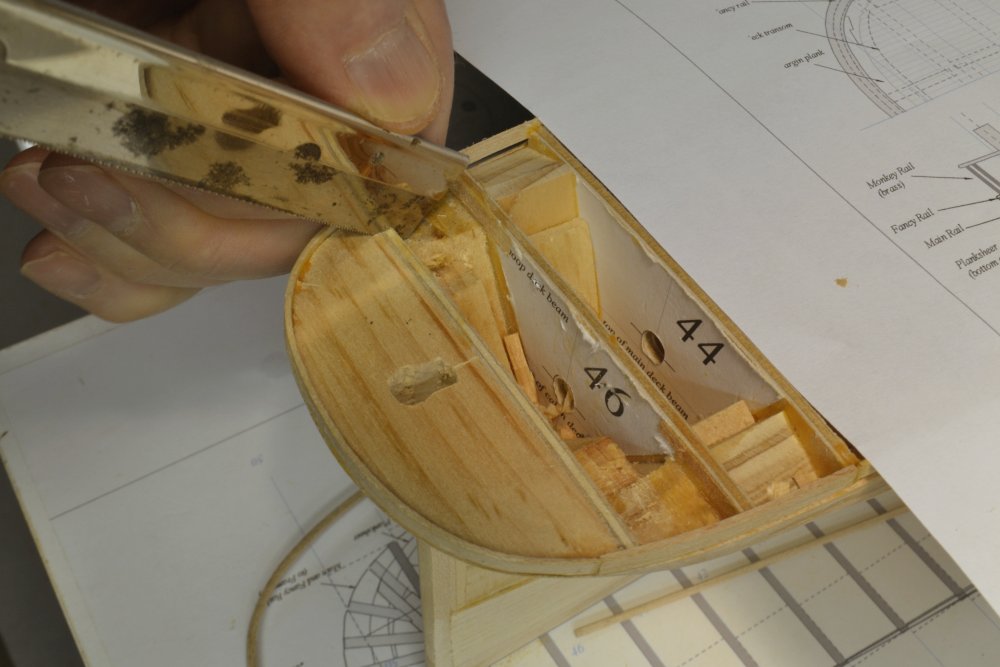
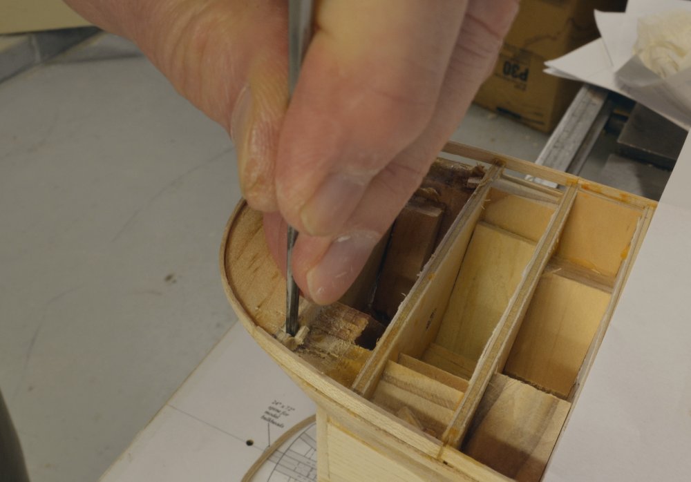
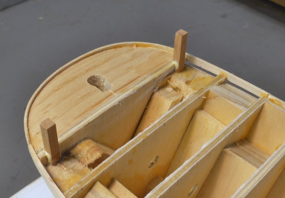
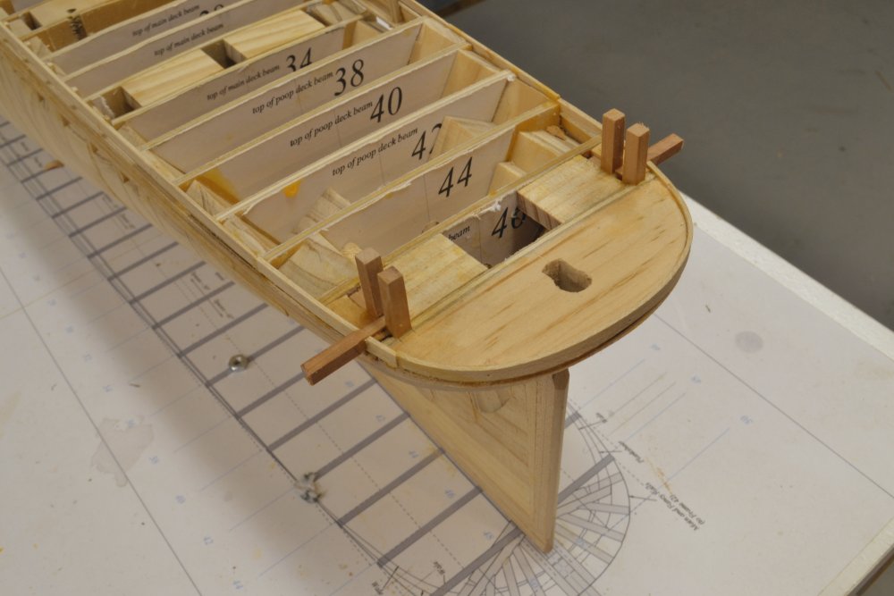
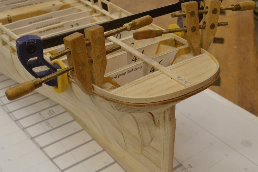
Young America 1853 – POB 1:96 Part 23 – Mooring bitts, Boomkins Before moving on to the hull planking, I decided to work on some structural details topside. The first of these chores was to install the aft mooring bitts and the horizontal timbers – boomkins - that extend outside of the hull to support the main yard braces and some other rigging. Because the plywood bulkhead spacing along the poop deck does not correspond to the actual poop deck framing, some surgery was needed to fit these structures. In the first picture a slot is being cut into the top of bulkhead 48 to fit one of the aft mooring bitts. The next picture shows the slot being chiseled out on the other side. In the next picture the two after bitts of the pair are being glued in. They will be cut down to size and shaped later. With these in place, wood chocks were fitted to both sides of the installed bits and between bulkheads 48 and 46 – to secure the forward bitts of each pair. The forward bitts are being glued in place in the next picture. A temporary pine spacer was placed between the bitts to provide correct spacing for the horizontal boomkins. Note the height of the outboard planking around the poop. This will permit the deck planking – specifically the margin plank - to be set flush with the top of these planks. This joint will be covered by the wide “fancy rail” at the top of the side. In the last picture the outer wood chocks and the outer planking have been notched and the boomkins fit between them. These too, will be cut to length and shaped later. The spacing between the bitts is actually smaller than the size of the boomkins, so they had to be mortised to fit into the allotted space. This last picture shows supporting chocks for the mizzenmast installed – at the top left of the photo. Because the bulkhead spacing is on main frame lines (Stations) only, there are no intermediate beams, carlings or headers for support of the various above-deck structures. Wood spacers, chocks, etc. have been put on the drawings for this purpose and will be installed in the next part. Ed


- 191 replies
-
- 23
-
-
- young america
- clipper
- (and 1 more)
-
Rudolf, Thank you for purchasing the book. I hope it meets your expectations. It should be no problem printing any of the pdfs on A4 paper. A4 is slightly narrower and also longer than letter sized, but the pdfs will fit. When printing from Acrobat or reader, simply click on page setup and change the printer paper size to A4 or do this in Printer Properties. Also make sure that "Actual Size " or "100%" is checked. Just to be sure,, check one of the dimensions after printing - for example the maximum breadth on the pattern for the deadflat. Good Luck. Let me know how it went. Ed
- 191 replies
-
- 4
-
-
- young america
- clipper
- (and 1 more)
-
No need for a ropewalk since wire will not require the "reverse twist" that thread fibers need to keep the strands together. Simply wrap the number of turns required around a small nail or pin with the other end around a hook in an electric drill and spin it up to the required diameter. Stretch the spun wire after spinning. If uncoated copper or brass is used, the spun wire rope may then be blackened with liver of sulfur (copper) or WinOx (brass) then buffed to a metallic sheen. Ed
-
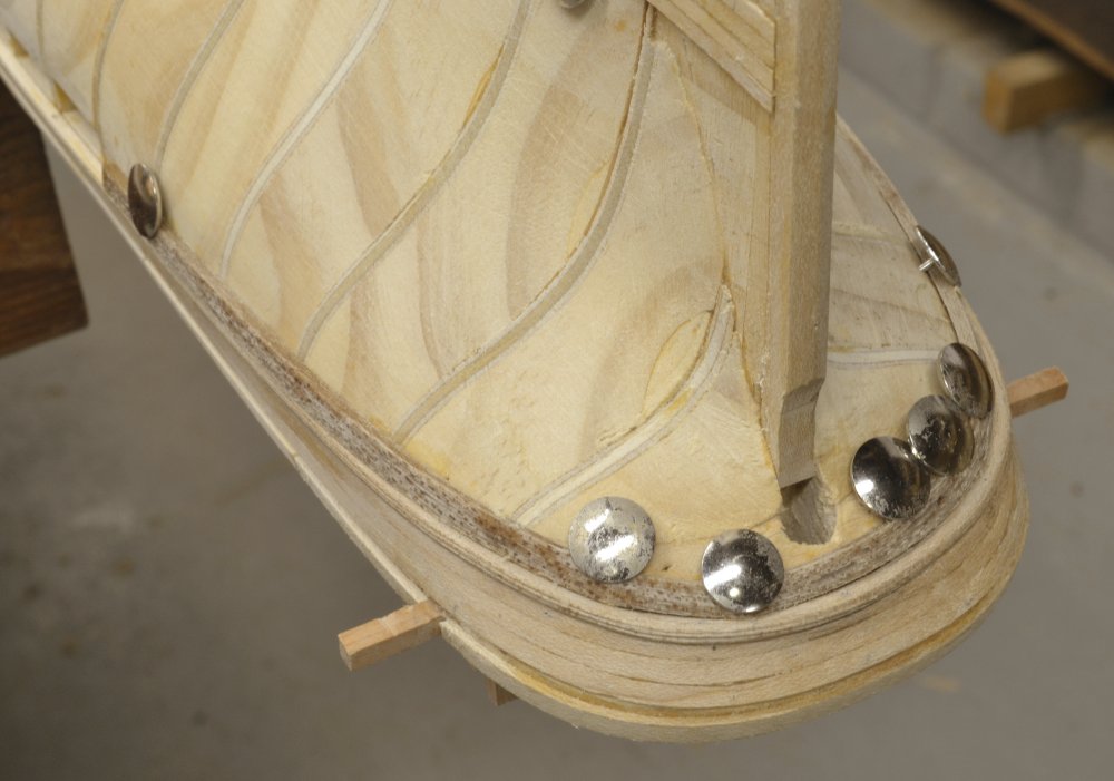
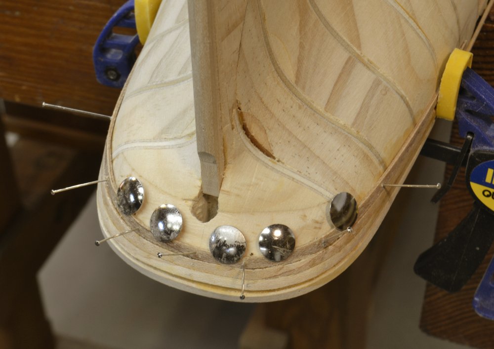
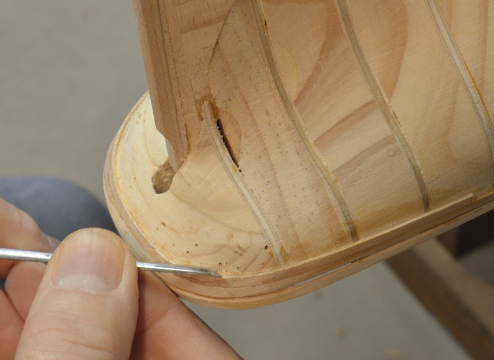
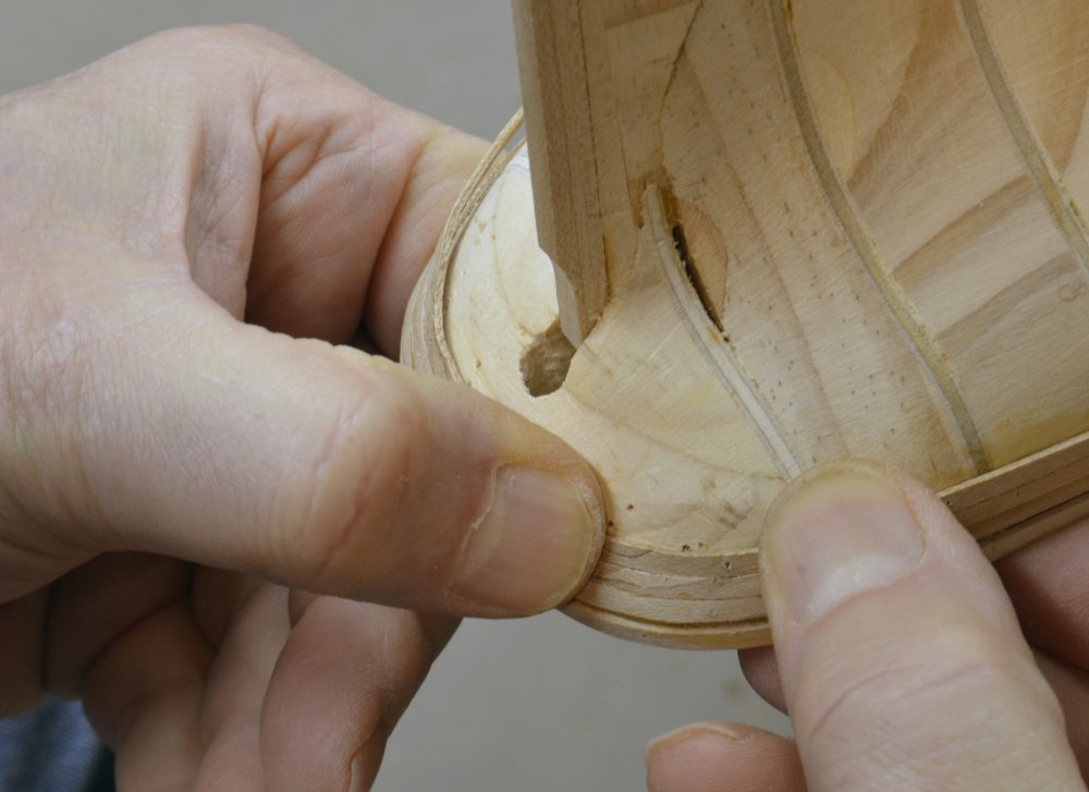
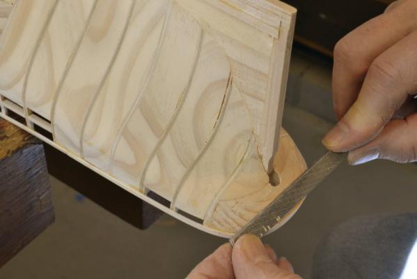
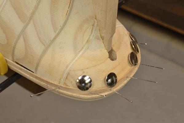
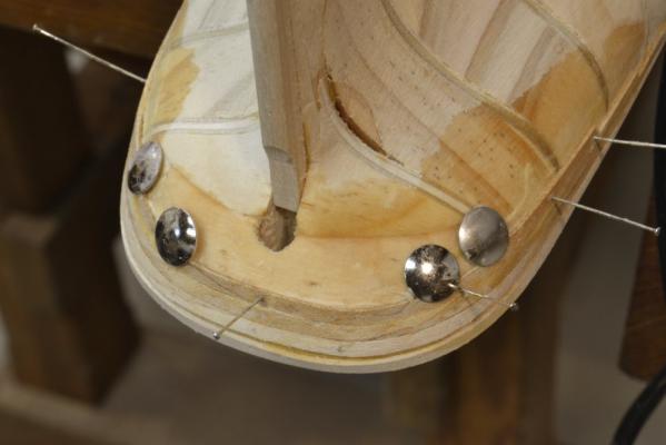
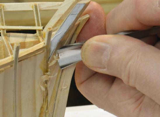
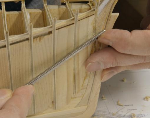
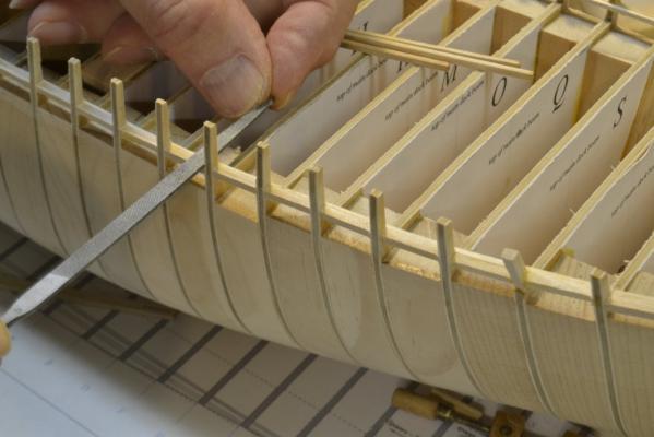
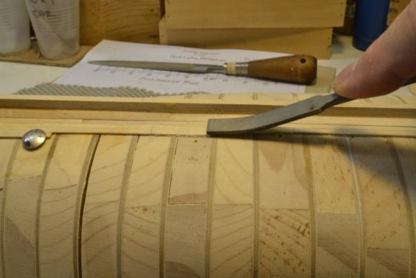
Young America 1853 – POB 1:96 Part 22 – Topside Works 2 In the last part, planking between the main rail and planksheer rail was shown installed. This planking is straightforward once the strakes around the elliptical stern are in place. It’s just a matter of continuing these forward to the stem. Fitting the strakes around the stern is a bit more complex, so I wanted to backtrack to show that work in some detail. The installation closely parallels the same work on the framed version, but is somewhat simpler because thumbtacks may be used into the solid filler block, whereas on the framed model the curved strakes had to be clamped to the stern timbers. In the first picture the main rail has been boiled and is clamped around the stern to dry just below the top planking strakes installed in the last post. The shape of this molding was scraped before boiling. When dry, the piece will be used to space the planking strake below. It will not be permanently fixed until much later after it and the hull have been painted. In the next picture the stern is being given some light final trimming with a rasp before beginning the planking. In the next picture the first plank below the main rail has been boiled, bent to shape, pinned in place and allowed to dry. The main rail shown in this picture is only temporarily fitted as a spacer. Because these planks are curved in two planes, it is difficult to get a perfect fit to the plank above without some trimming before final gluing. This was done as each strake was installed – to get a neat fit with the one above. The next picture shows the third strake below the rail tacked and pinned in place for drying. The gaps in the joints with the adjacent strake above can be seen. In the next picture the second strake is being trimmed with a paring chisel to accept the next plank. Both sides of the joint got some slight trimming. In the next picture the curved third strake is being checked for fit with the one above. This strake is being glued in place in the last picture. To allow for the trimming and fitting of this planking – and also the final levelling – planking strips were slightly oversized to start. I find this method of fitting these curved and twisted planks less work than spiling. The two dimensional curving of the planking strips requires significant boiling time (say an hour) and use of an easily bendable wood species – in this case straight-grained hard maple. I doubt that this degree of shaping could be achieved with kiln-dried Castelo that would be a likely choice for an unpainted model. This one will be painted. Ed


- 191 replies
-
- 26
-
-
- young america
- clipper
- (and 1 more)
-
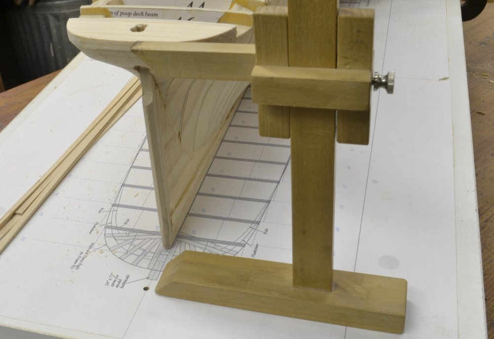
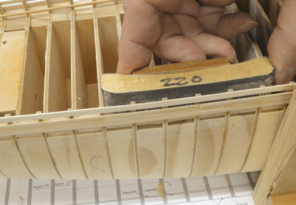
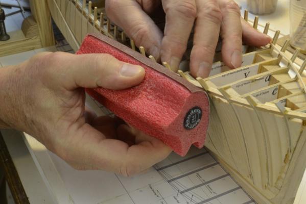
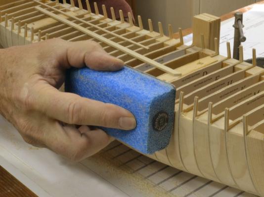
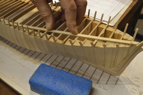
Young America 1853 – POB 1:96 Part 21 – Topside Works 1 Because of the fragility of the plywood toptimbers, a slightly difference sequence was followed in constructing the topside bulwarks on POB model vs. that used on the full framed version. To reinforce these toptimbers and allow them to be faired and sanded smooth on the inside, the top strakes of planking just above the main rail were installed first – beginning at the elliptical stern. These two upper strakes were installed using one planking strip. In the first picture a strip has been boiled for bending and is clamped around the stern at the top for drying. In the next picture, a final check of the height of the stern at the centerline is being checked against the drawing using the height gauge. Last chance to make sure the height is correct. The decking of the poop was flush with the top of the side planking, allowing the fancy rail to cap the side and deck planking. In the next picture a gauge strip of deck plank thickness (3 ½”) is being used to check the side planking height as it is glued and pinned in place. The top plank was then continued forward to the stem as shown in the next picture. The height gauge was used throughout the installation of this upper strake to ensure an accurate line. The next picture shows some more of the installation of the upper strakes. Once the work has proceeded forward of the poop deck and the plywood bulkheads, clamps were used in lieu of the pins as the planks were glued. In the next picture the upper side strakes are complete and the tops of the timbers are being levelled off at the correct height using a fine rasp. This could not be done safely without the upper strake in place. Before sanding the insides of the toptimbers, outboard planking between the main rail and planksheer rail was installed. I will cover fitting of this planking around the stern in a later post. A temporary spacer was used to set the gap that will eventually be filled with the painted main rail. In the next picture the planking down to the planksheer has been installed and the insides of the toptimbers are being faired with a Softsander® pad fitted with 120-grit paper. In the last picture the insides of the toptimbers are being sanded smooth with 220-grit paper. At this stage the upper works were quite strong, the toptimbers sanded smooth and ready for the next step – installation of the inboard parts of the main rail. Ed


- 191 replies
-
- 26
-
-
- young america
- clipper
- (and 1 more)
-
Laman, Thanks for your comments on the book. I hope all goes well with your Naiad build. I would have reponded sooner but we have been away and I don't check in as often. Ed
-
Daniel, Bob Friedman will be at the conference and will be taking orders. I also understand that he will have a limited number of copies there for sale. I expect to be there with both models as well. Ed
-
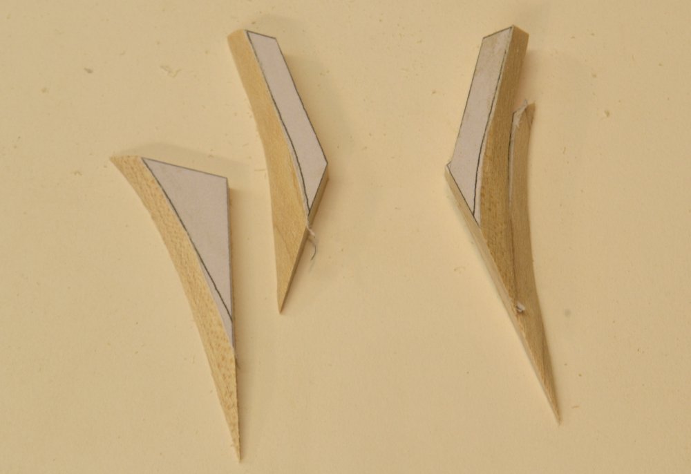
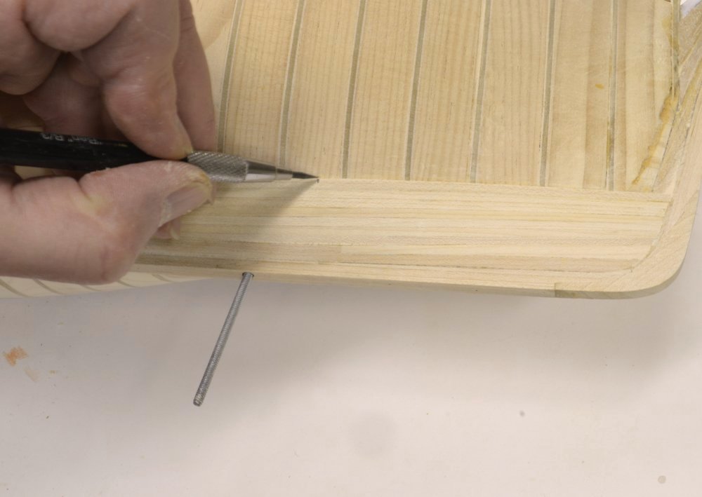
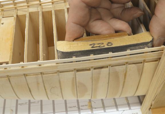
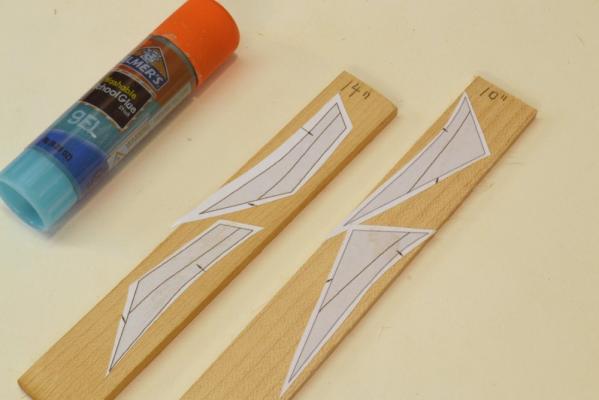
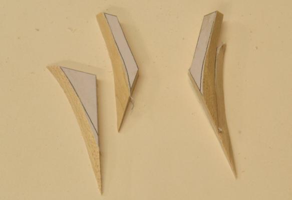
Young America 1853 – POB 1:96 Part 20 – Knightheads The knightheads reinforced the stem on either side and provided a base for securing the hawse timbers that formed the forward hull back to the first cant frames. This detail is shown in the posts for the full framed version of the model. Rising above the top of the sides, the knightheads also provided lateral support to the bowsprit. To accommodate the 36” square section of the bowsprit, additional space was provided between knightheads by additional members, 10” thick stem timbers, bolted to the sides of the stem assembly. The two 10” stem timbers astride the 16” thick stem provided the necessary 36” spacing for the bowsprit. On the POB model only the upper parts of the knightheads and stem timbers were modeled. In the first picture their patterns have been pasted to the correct size stock. As with all of the stock for this demonstration model, ¾” wood was used, allowing all the thicknesses to be cut on a good model circular saw. This was done to allow the model to be made from readily available stock without the need for a thickness sander/planer – a rather expensive tool and not one that beginning scratch builders might have. In the next picture the members have been cut out and given an initial bevel based on the pattern lines. These were cut from hard maple. The knightheads will be exposed on the model but painted black. The members to the right are shown in their relative positions. In the next picture the starboard head timber is being fitted into the space between the stem and the most forward bulkhead. To prepare for this, the pine spacers forward of the first bulkhead were removed by sawing and paring with a straight chisel. These spacers had been installed to protect the forward bulkhead during initial rough fairing of the hull. In the next picture the breadth across the installed head timbers is being checked for the eventual fit of the bowsprit. At 1:96 the breadth needs to be 3/8”. This precise breadth was obtained by sanding the sides of the members after they were glued in. In the next picture the port knighthead is being glued into place. With both knightheads firmly secured they could be faired into the stem rabbet. In the next picture a gouge is being used for this. With the shape roughed out with the gouge, a curved rasp was used to refine it – as shown below - followed by 120-grit sandpaper. With the knightheads in place and faired, the topside planking could begin. Ed

- 191 replies
-
- 31
-
-
- young america
- clipper
- (and 1 more)
-
Young America 1853 – POB 1:96 Part 19 – Planksheer In the angle between the toptimbers and main deck beams, a massive 12” x 11” waterway was fit to reinforce the deck beam connections to the frames and to provide a watertight seal around the outer deck planking. The planksheer was a large member that fit directly on top of the waterway and enclosed the toptimbers. It provided a watertight cap over the hull frames, waterway and outboard planking. It was wide enough to show as a molded rail both outboard and inboard. It was either mortised to fit down over the toptimbers or, more likely, made in two parts that were notched to fit both inside and outside, then bolted through horizontally. On the model, I installed the planksheer as spacers between the toptimbers capped by rails inside and out. Since the planksheer rests on the waterway which in turn rests on the deck beams, I believe the height of the planksheer is most accurately set by fitting the inboard rail first. The height was set using a temporary pine spacer cut to the depth of the waterway. This is shown in the first picture. Why not install the waterway first, then the planksheer? If the model is to be painted, the waterway will be painted blue, the inboard works, including the adjoining inboard planksheer rail white. To avoid having to cut in sharp paint lines after construction, I wanted to paint the white then install the pre-painted blue waterway below it. The natural finish decking would later be installed against the blue waterway. The sequence to accommodate painting is also described in the posts for the 1:72 framed model – as well as in detailed in the book. The inside rails were molded using a scraper and cut to size as described for the larger version. With the inside planksheer rail glued in place to the toptimbers, spacers between toptimbers were cut and fitted – glued to the outboard face of the inner rail and end glued between toptimbers. In the next picture, these spacers have been installed and their outer edges are being faired to the outside of the frames. In the next picture the tops of the spacers are being filed flush with the top of the inside rail. The upper face of the rail is horizontal in the athwartship direction. Before the outer part of the planksheer or any exterior planking could be installed, it was necessary to fit the knightheads. I will describe that work in the next part. Ed

- 191 replies
-
- 23
-
-
- young america
- clipper
- (and 1 more)
-
The N.C. Wyeth paintings illustrating the book are alone enough to recommend the set - at a much higher price. Ed
-
Thank you all for these very supportive comments and for the interest expressed in the book. The clipper era and the extraordinary ships themselves provide fascinating subjects for study and modeling. I hope the book will introduce many to this somewhat neglected ship modeling area. As for the NRG conference that some have mentioned, I plan to be there with both Young America model versions, completed to the extent described in Volume I. Bob Friedman will also attend and will take orders for all Sea Watch Books. I believe he plans to bring a limited number of copies of my book for direct sale. I will be happy to add my unintelligible script to these. Robin, it is good to hear from you. I have been a fan of Derek Gardner's work for many years and have two of his watercolor prints hanging over my desk. I was delighted to discover his painting of Young America and even more excited that we could obtain rights to use it on the dust jacket. The painting certainly captures the essence of the clipper ship under sail and well depicts Young America in her early career with her massive single topsails. Ed
- 3,618 replies
-
- 9
-
-
- young america
- clipper
- (and 1 more)
-
Thanks, Allan. In your picture I'm trying to figure out which one of you got caught. Ed
-
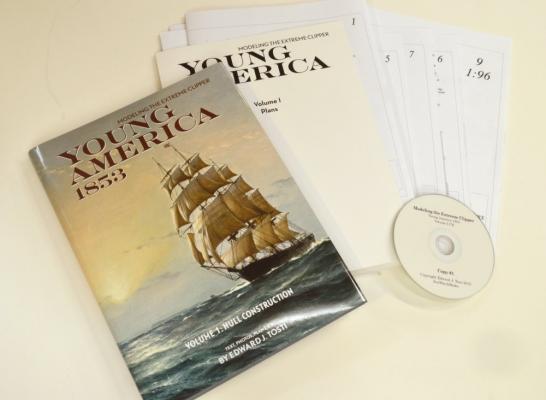
The Book is out! Sea Watch Books and I are very proud to announce the publication of Modeling the extreme Clipper Young America 1853, Volume I. I think you will find that the book is unique in its description of a fully-framed extreme American clipper - as well as a smaller plank-on-bulkhead version. As with the Naiad books, the focus of this work is on modeling processes - covered in detail with many photos and drawings. Eight full sized drawings are included for the two versions as well as a CD containing patterns, detail sheets and other data. A second volume covering fitting out, masting and rigging is planned. My contribution to the book has included almost three years of research, drafting,modelbuilding, taking a few thousand photos and, of course, writing. I will let Bob Friedman comment on the effort required by Sea Watch and its various subcontrators. However, apart from this initial announcement, the purpose of this topic is to collect comments, questions, and opinions on the book. Bob Friedman and I will pay attention to these as the book rolls out and address questions or issues that may arise. I will use this topic to post any addenda to the work that may become necessary or even just useful. There are plenty of people to thank for help with an effort like this and I hope I have adequately expressed appreciation in the beginning of the book. The late Bill Crothers (1912-2015) tops my list and therefore deserves additional mention here. His exhaustive work on the structures of the American clipper ship were a primary resource for me and neither the model nor the book would exist but for his many years of effort and his excellent books. It was my honor and pleasure to meet with Bill with the framed version of the model in its earlier stages and to discuss various topics by phone on a number of occasions. I regret that he is not here to see the either the current model or the book. So, comments and questions are most welcome. Ed The book can be found at: http://www.seawatchbooks.com/NewsForthcomingBooks.htm

- 56 replies
-
- 21
-
-
The Book is out! I hope I may be permitted some euphoria over the publication of Modeling the Extreme Clipper Young America, Volume I. It took a lot of effort by Sea Watch Books and me to get this to market this year. There were times early in the year when the amount of modeling and writing required to meet this deadline seemed insurmountable. All the generous and supportive responses to the two build logs on this site helped us keep our nose to the grindstone. The picture below of the book and its supplementary material hardly does justice to Derek Gardeners beautiful rendering of Young America on the Irish Sea on a winter’s morning as she approaches Liverpool – but it does serve as proof that the book is in print. I have examined every inch of this first copy and am delighted with the result. We hope you will be as well. As I did with the Naiad books, I will start a topic in the book review section for comments, questions, addenda, and what I hope will be very few corrections. In the meantime, this posting on each of the two build logs will at least serve notice that the book is out. Thanks again for all your support. Ed

- 3,618 replies
-
- 36
-
-
- young america
- clipper
- (and 1 more)
-
The Book is out! I hope I may be permitted some euphoria over the publication of Modeling the Extreme Clipper Young America, Volume I. It took a lot of effort by Sea Watch Books and me to get this to market this year. There were times early in the year when the amount of modeling and writing required to meet this deadline seemed insurmountable. All the generous and supportive responses to the two build logs on this site helped us keep our nose to the grindstone. The picture below of the book and its supplementary material hardly does justice to Derek Gardeners beautiful rendering of Young America on the Irish Sea on a winter’s morning as she approaches Liverpool – but it does serve as proof that the book is in print. I have examined every inch of this first copy and am delighted with the result. We hope you will be as well. As I did with the Naiad books, I will start a topic in the book review section for comments, questions, addenda, and what I hope will be very few corrections. In the meantime, this posting on each of the two build logs will at least serve notice that the book is out. Thanks again for all your support. Ed
- 191 replies
-
- 27
-
-
- young america
- clipper
- (and 1 more)
-
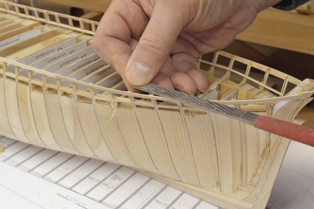
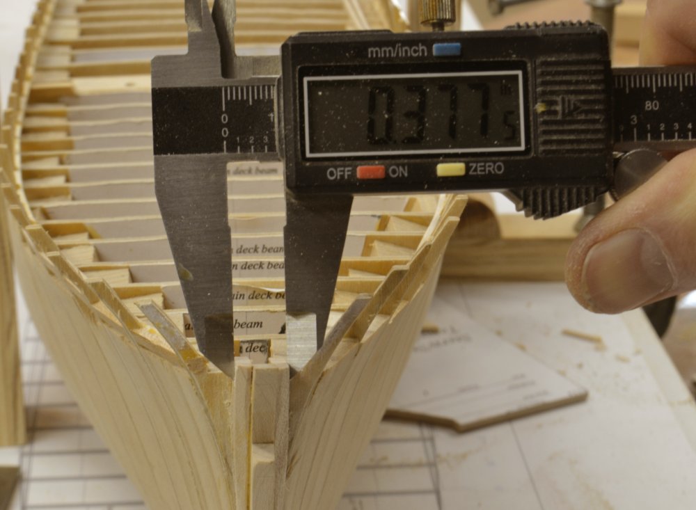
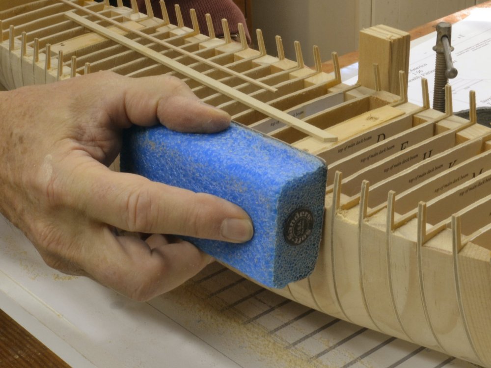
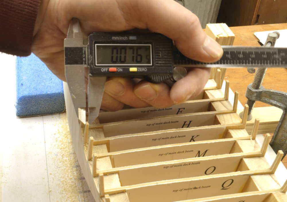
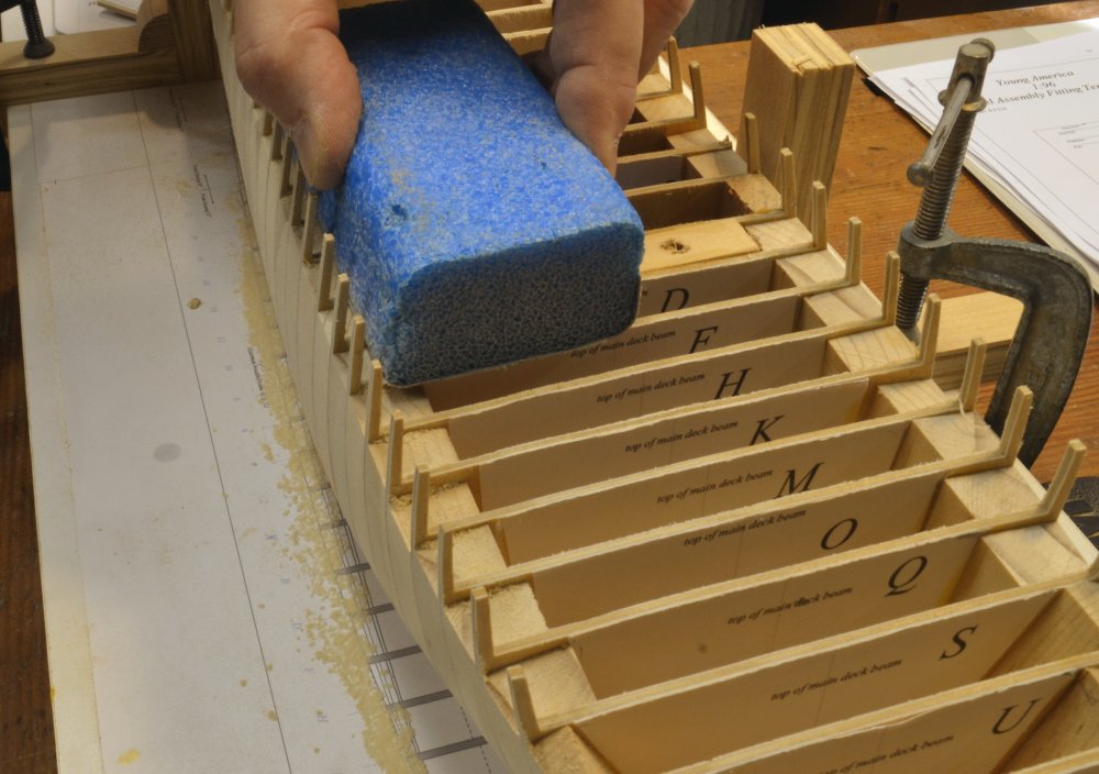
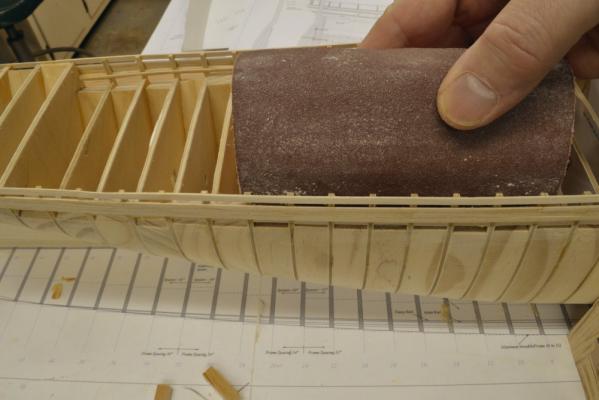
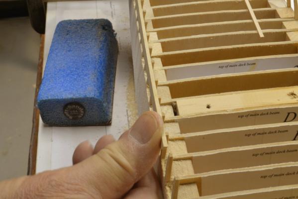
Young America 1853 – POB 1:96 Part 18 – Fairing the Upper Works When the hull was faired earlier, in the inverted position, little attention was paid to the upper works, so the outside of the toptimbers needed some work. The sanding required to fair the outside of these was light. The first picture shows this in progress using 220-grit paper on a Softsander® foam pad. In the next picture the fairness is being checked with a pine batten. The toptimbers were molded 6” at the top. In the next picture this is being checked with calipers. You can see from the reading that they are still oversized somewhat at .076”. They would later be faired to the final 6” (.0625”) by sanding the insides – but only after some reinforcing outer planking was in place. However, it was necessary at this stage to fair the deck “beams” accurately – as shown in the next photo. Fairing of the deck was particularly important to avoid waviness in the thin deck planking that would be added later. In the next picture this is being checked during the sanding process using a pine batten. When this work was being done, I did not expect to take this model to much further and consequently spent less time getting the deck line faired than I should have. I will show the final deck planking later. While acceptable, more attention at this stage would have yielded a truly beautiful installation of the long, spacious open main deck.. With this work completed, the construction of the topside planking and rails could begin. Ed

- 191 replies
-
- 25
-
-
- young america
- clipper
- (and 1 more)
-
Druxey, Actually, I was referring to the thickness of the planks, not their widths. The width of the planking on these ships was usually about 6" - rather narrow compared to what most of us are used to. I used a common width of 8" below the wale. I do not intend to actually sheath this demo model or paint it below the waterline, so 8" seemed a reasonable compromise. I take your point though. It was a lot of work - even with no treenails. I also left the port side unplanked from somewhat below the top of the wale - to display the bulkheads and spacers. I am planning to bring this model - and big sister - to the NRG conf. Ed
- 191 replies
-
- 9
-
-
- young america
- clipper
- (and 1 more)
-
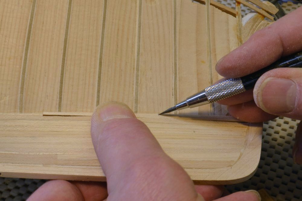
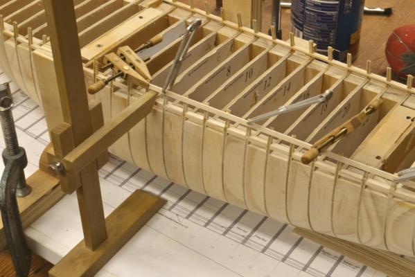
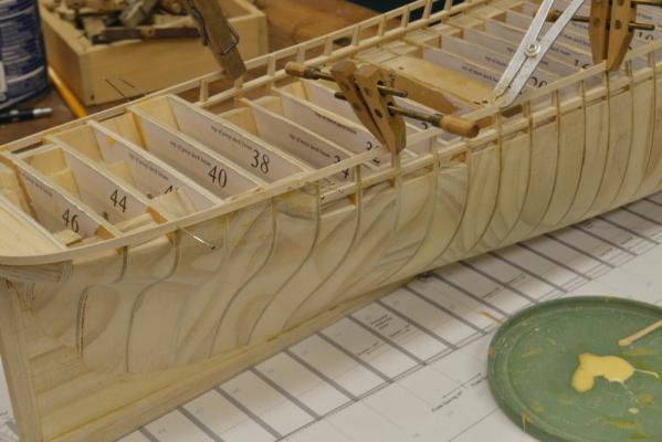
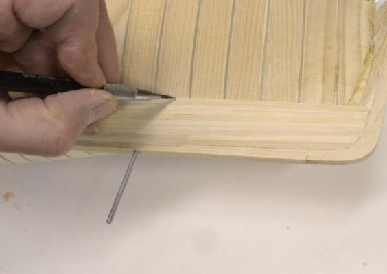
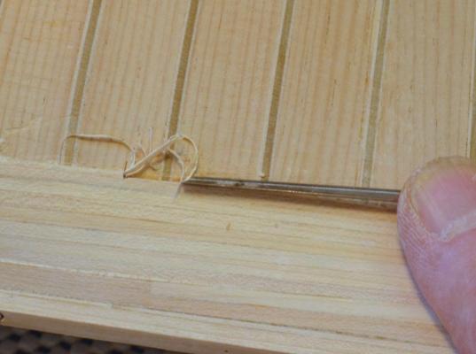
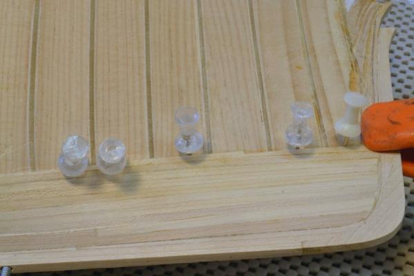
Young America 1853 – POB 1:96 Part 17 – Bottom Planking I have mentioned a number of times that the 1:96 POB version shown in these posts was constructed as a demonstration model for the book (now available from SeaWatch). After reaching this stage in the build, the text in the book applies equally to both models and the same methods apply to complete either model. For all of that subsequent work, the 1:72 model was used in the descriptive photos to avoid confusion and the excessive space requirements to show both. Although I believe the book describes both versions well, I thought that anyone wanting to build the POB version would find the many pictures I was taking useful and interesting. For that reason (and because I was having fun with this version) I decided to take it to a further state of completion and post pictures of that work here. There is no bottom planking on the fully framed model, but this version would clearly require full planking to cover the bulkheads and spacers. The first picture shows the first several strakes above the thick garboard being installed. I used hard maple for all this planking. The picture shows typical clamping. Thumb tacks proved very useful and easy to use on this work. The soft pine spacers between bulkheads allowed these to be pushed in by hand but some required tapping with a hammer. The clamps were used to close the planking joints in the very lowest strakes. The next picture shows the planking being levelled off next to the thicker garboard using a flat #0 cut riffler, one of my favorite tools for this kind of work. The bottom planking is 4” thick above the garboard. I ripped the planks to 5” to allow for some smoothing out and some finish sanding. Since all of the planking on this model would likely be painted or metal sheathed, I dispensed with pre-painting the edges of the planks and the use of dark glue. The next picture shows some work near midship. Drawing pins also work well in the pine substructure as shown in the next picture, but in general I used thumb tacks. The type with plastic covered heads are best. With the tapping in and prying out the attrition rate on thumb tacks was high. The clamp shown at the stem applies quite a lot of pressure to hold the “hooding ends” tight in the rabbet. As planking begins to proceed upward, additional strakes need to be cut in at the ends so that the planking will eventually match the sheer of the wale above. I began inserting these - as shown in the following pictures – when the lines of planking began to appear drooped at the ends when viewed from the side. In the first picture the cutting in point is being marked. In the next picture the installed plank is being pared back to one-half its width while preserving a fair line forward. In the next picture the partial strake has been fitted and is, itself, being marked for another cut in strake. In the next picture that strake is being glued in place. Although difficult to see in this last picture, the same process was applying at the stern. At about this point, work on the lower planking was discontinued until later and the focus shifted to the upper works where much work awaited. Ed


- 191 replies
-
- 29
-
-
- young america
- clipper
- (and 1 more)
-
My purpose in the note was to ensure people were not left with the impression that the white main rail was wrong or that there is any real question about deck heights. Ed
- 191 replies
-
- 3
-
-
- young america
- clipper
- (and 1 more)
-
Thank you, David. I hope the book measures up. And thanks for all the likes on this log. I have intended it to be a useful supplement to the POB related text and pictures in the book. I feel I have been neglecting the full framed "big sister" for the past couple months but hope to be back posting on that log soon. Rob, you are right about changes in service and painting would seem to be the most likely to vary. I would not be too quick to judge Bill Crothers wrong on this - the paint scheme of the original ship. He was generally very meticulous about his sources. The two known photos showing the black main rail were taken years after the launch as indicated by the single stick upper masts that were not in the original design or even in the configuration of 1854 when the Howes double topsails were added. On the levels of the deck relative to the topside, I spent some time looking at this when drafting the plans for YA, because the poop rail seems very low relative t the deck height. However I soon found that Webb's initial offsets are quite definitive as is one of the photos that clearly shows men standing on the poop at the level of the fancy rail. The height of the poop rail may also be measured from this photo. The heights of the planksheer rail given on the original offsets, coupled with the known depth of the main deck waterway, leave little doubt as to the correct deck heights. So I guess you could say that Webb himself has the last word on this question - in what seems to be his own fine hand. Cheers, Ed
- 191 replies
-
- 9
-
-
- young america
- clipper
- (and 1 more)
-
Actually, I find that I have seen pictures of the model before. Here is another I found in my file: Ed
- 191 replies
-
- 7
-
-
- young america
- clipper
- (and 1 more)
-
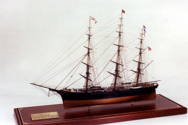
Thanks, everyone for all the likes and the comments. That certainly is a beautiful model, Rob. I do not believe I have seen it before. I note the black main rail, which is evident in the two existing photosof the actual ship. I followed Bill Crothers advice on paint and made mine white and that introduced some complexities into the build to avoid having to paint that line after construction. The black looks so good I am not sure it was worth the effort. Bill certainly had access to the photos before recommending the paint scheme, but his source is not clear - at least I have not turned it up yet. I also note in the model picture that the fancy rail along the top of the side is also painted black and that the top of the side rises above the poop deck and is therefore higher along the other decks as well. This may not be correct and differs from the design I used. Ed
- 191 replies
-
- 2
-
-
- young america
- clipper
- (and 1 more)