EdT
-
Posts
2,214 -
Joined
-
Last visited
Content Type
Profiles
Forums
Gallery
Events
Everything posted by EdT
-
Rchard, has your last post been moved? I had a notice for it. Certainly no problem to start another thread, however, if your questons are related to Naiad book content, I suggest you post them here because I follow this thread. I do not follow all the other threads regularly and so will be unlikely to respond to questons there. Just so you know. Your questions on taps and dies are certainly more genral in nature so I am sure you will get good responses on other threads. Ed
-
Rchard, the major diameters given are the outside of he threads. You should reduce the rods to that diameter before trying to thread them with the die. If the rod is oversized it will bind in the die. Also if the rod diameter is too large the threaded rod o.d. will be too large and will not turn smoothly in the threaded hole. If you do not have a lathe to turn the rods, you can chuck them in a drill and reduce the diameter with a flat file (or even with sandpaper -but the file is better.) If you search the web for "screw thread dimensions" you should find some diagrams showing the various thread measurements. Ed
-
Thank you all again for these comments and for all the "likes." Daniel, that is a very nice diagram. It is similar in some structural aspects to YA, but the hull shape is much fuller. Druxey, the progress was faster than I expected. Perhaps everyone might be interested in some comparisons with Naiad: This point was reached on Young America in 5 months - on Naiad 11 months. Naiad had 61.5 frame pairs (41.5 full and 20 cants) consisting of about 960 frame pieces including chocks. YA has 80 frame pairs (50 full, 19 half and 11 cants) - also about 960 pieces. In spite of the scale difference (Naiad 1:60, YA 1:72), the frames are very similar in size. I attribute the more rapid progress on YA to the following: Although the number of pieces in total are about the same,YA frames are simpler - no chocks, all are sistered with no spaces - no free standing frames. I cut Naiad's gunports after all this work, so it was not a factor. The frame assembly process used on YA was very much faster. Using the pin-indexed process, assembly time was about one-quarter that on Naiad - even with the full bevelling on YA's frames before erection. Naiad's frames were only roughly bevelled. Frame erection was also much faster. With the paired frames there were fewer individual pieces to erect. Cant and half frame setting was very fast using the planksheer ribband method - no more than five to 10 minutes per side for a pair. YA probably also benefited from my ascension on the framing learning curve since Naiad. Although I was still experimenting with different processes on YA, I am sure that had an effect. Again, thank you all for your comments and interest. Hopefully the rest of the project will go as well. Ed
- 3,618 replies
-
- 3
-

-
- young america
- clipper
- (and 1 more)
-
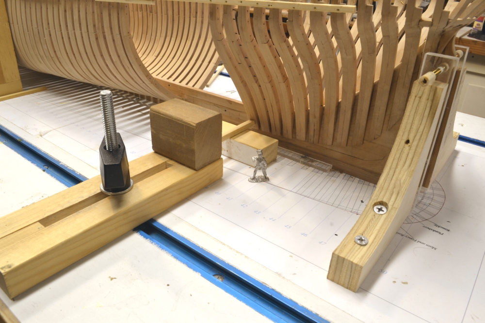
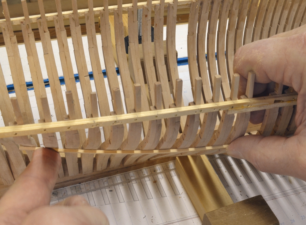
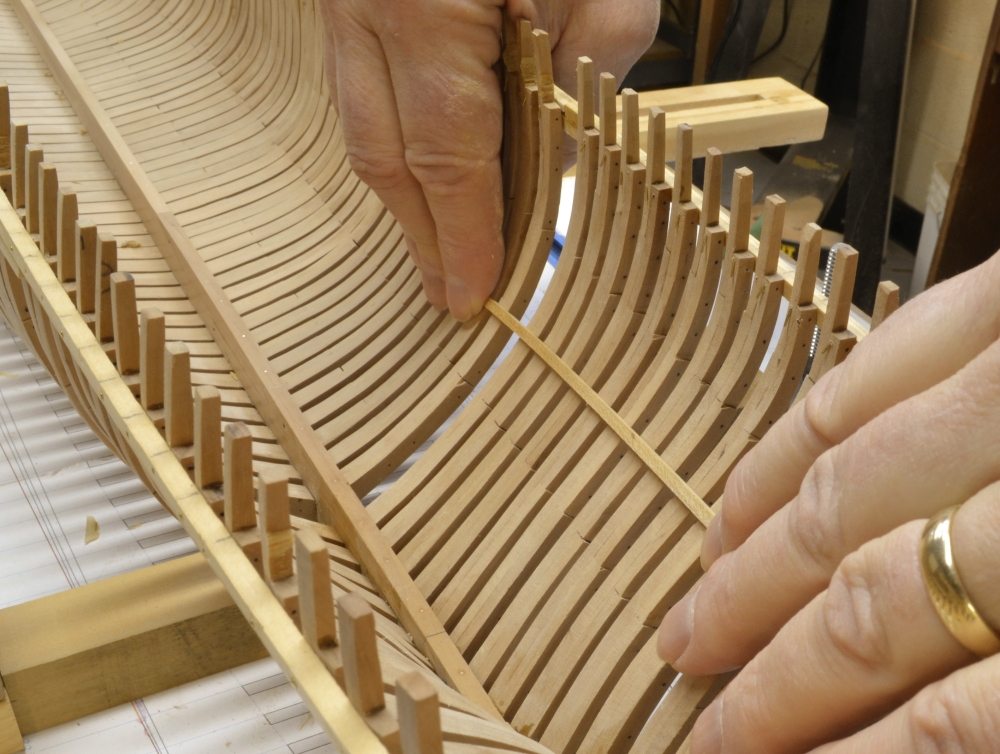
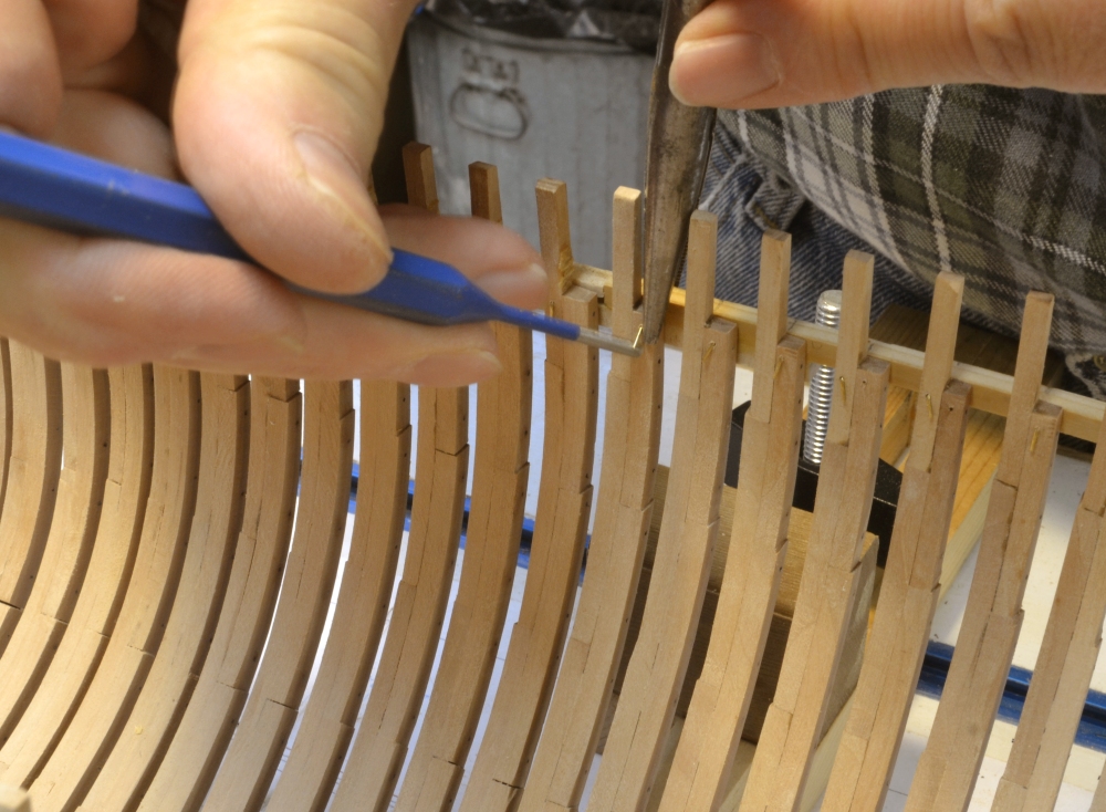
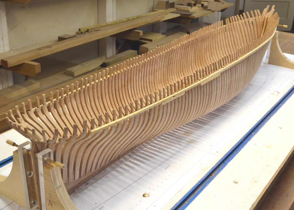
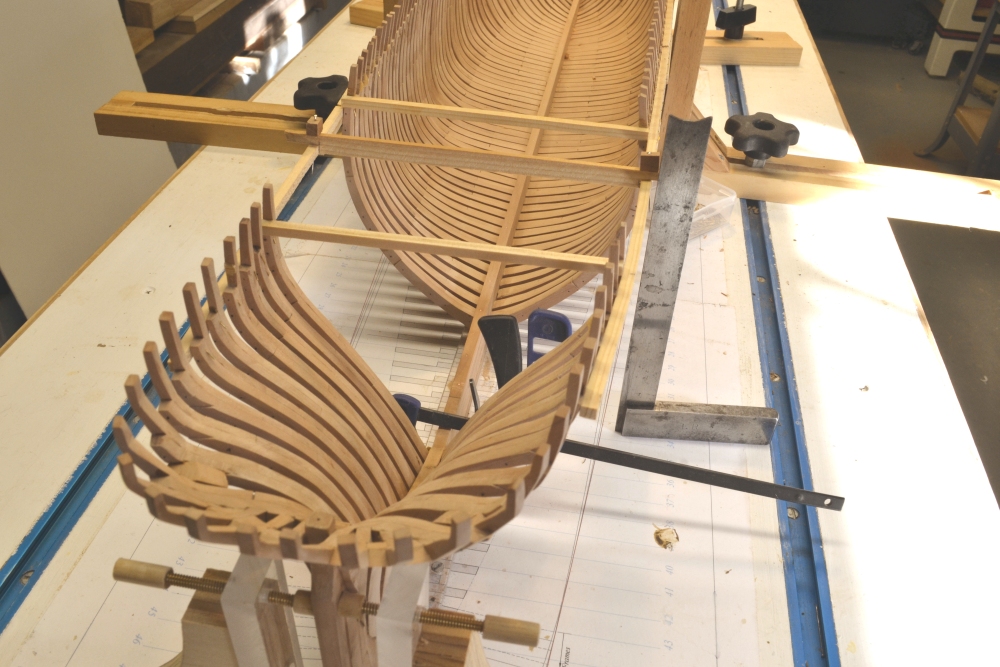
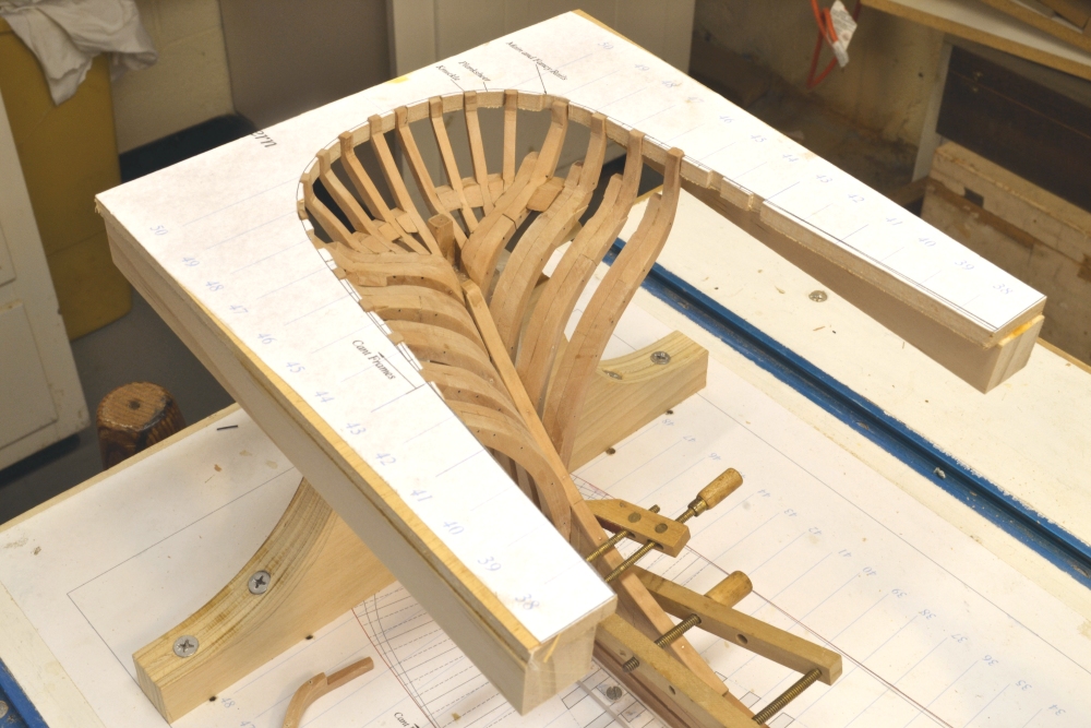
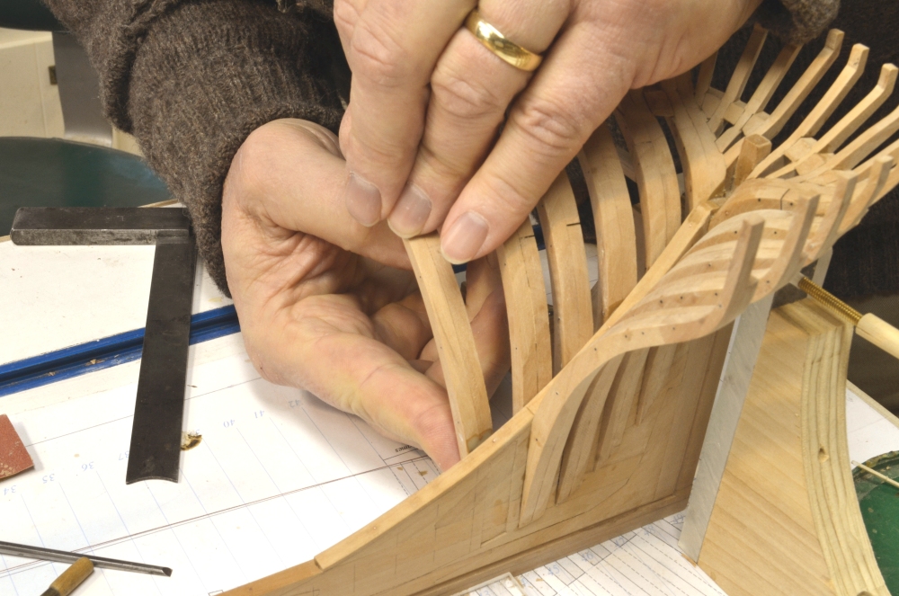
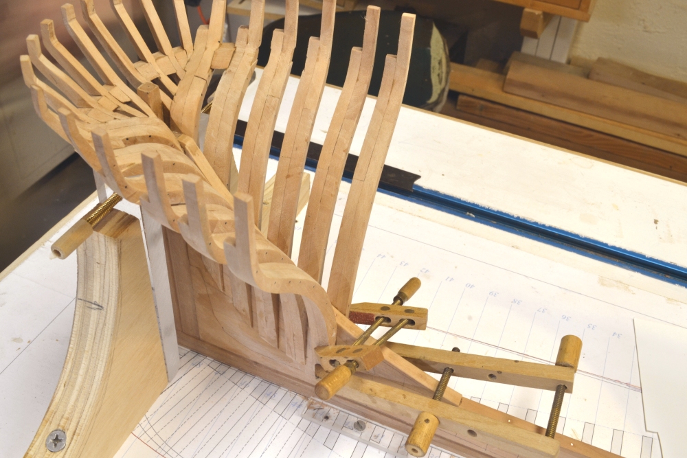
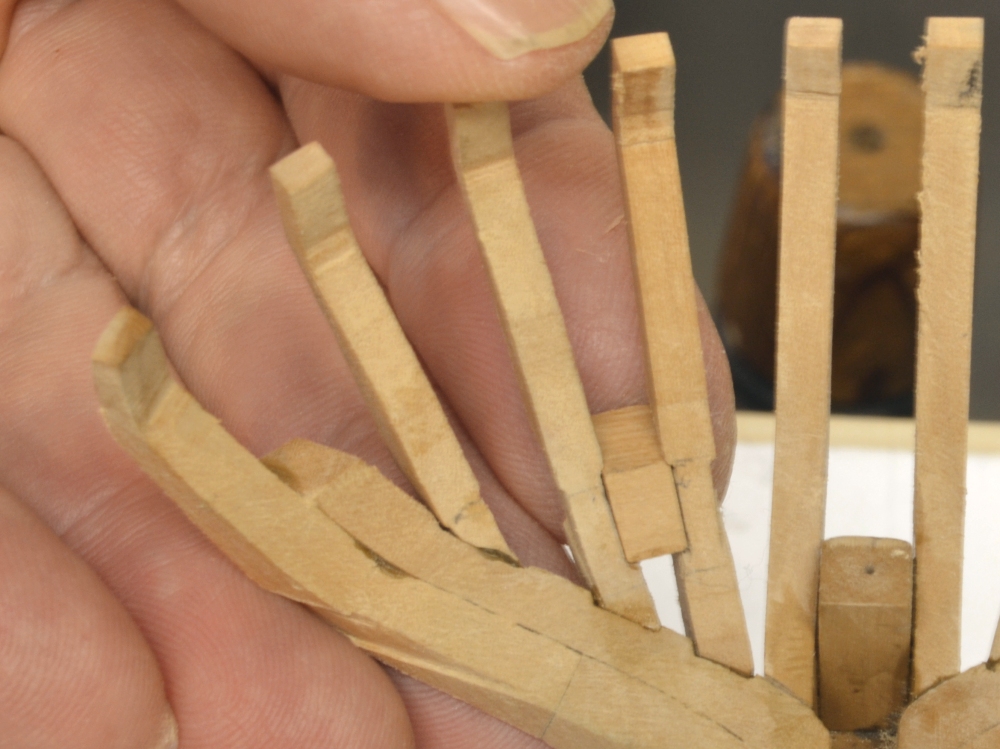
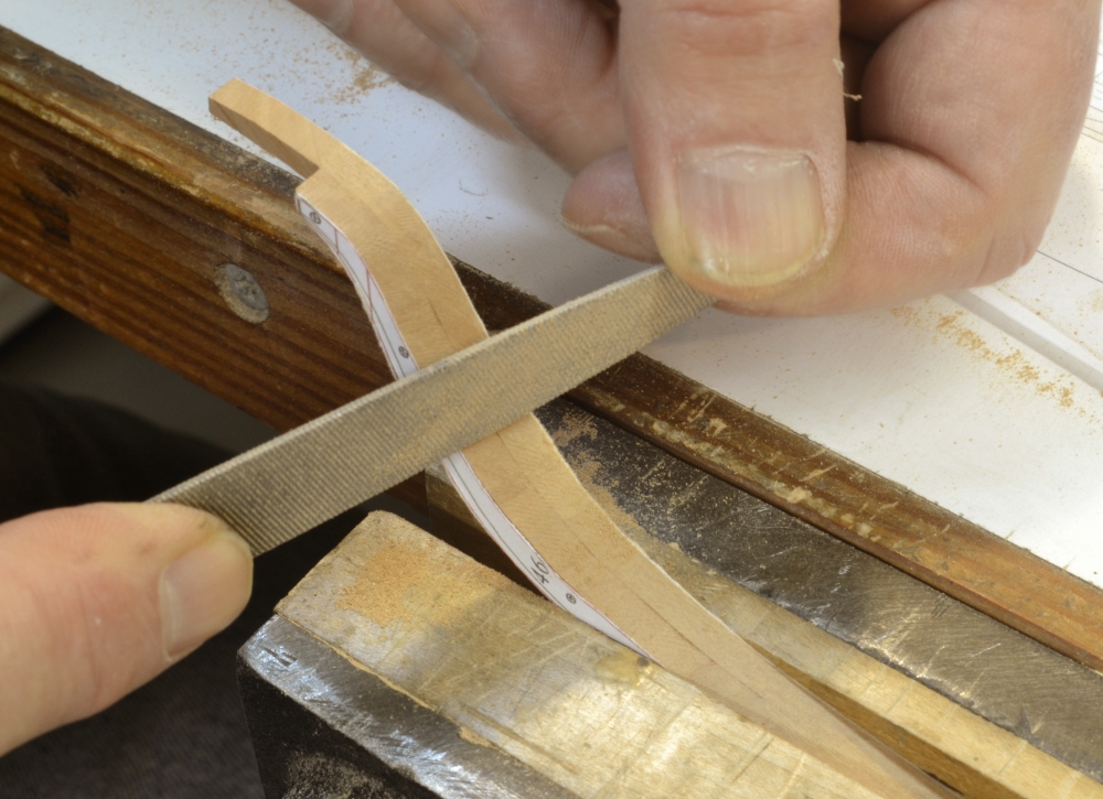
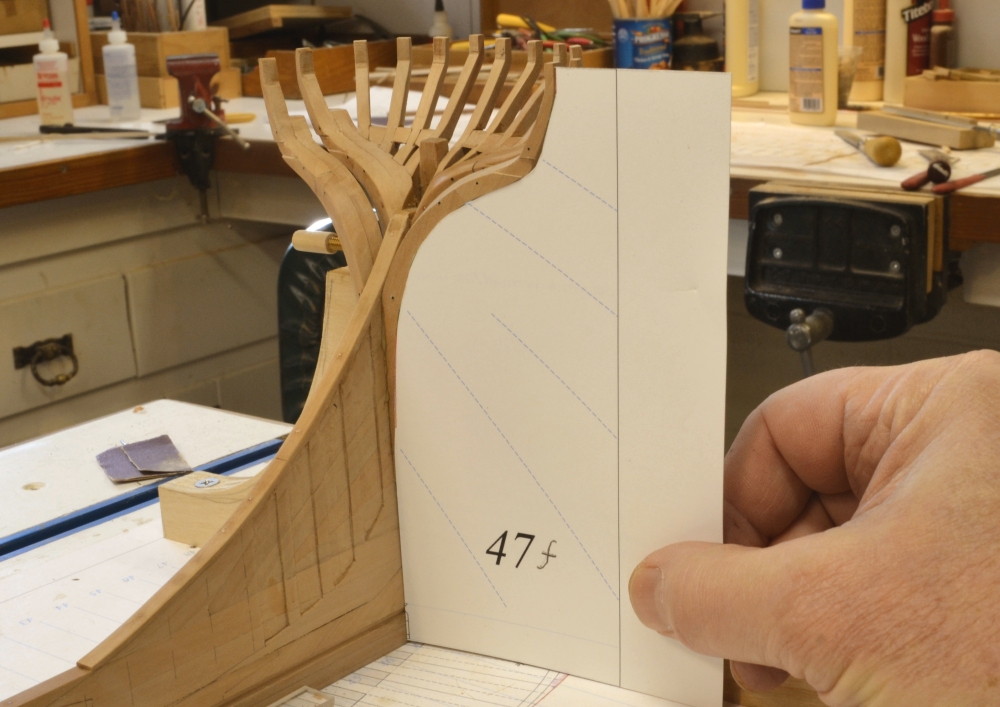
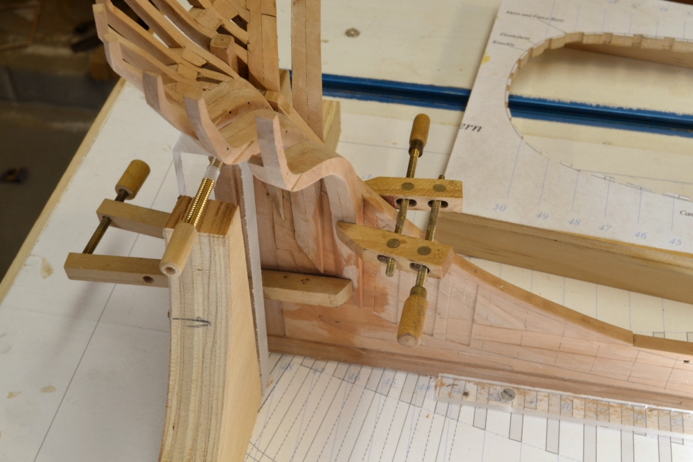
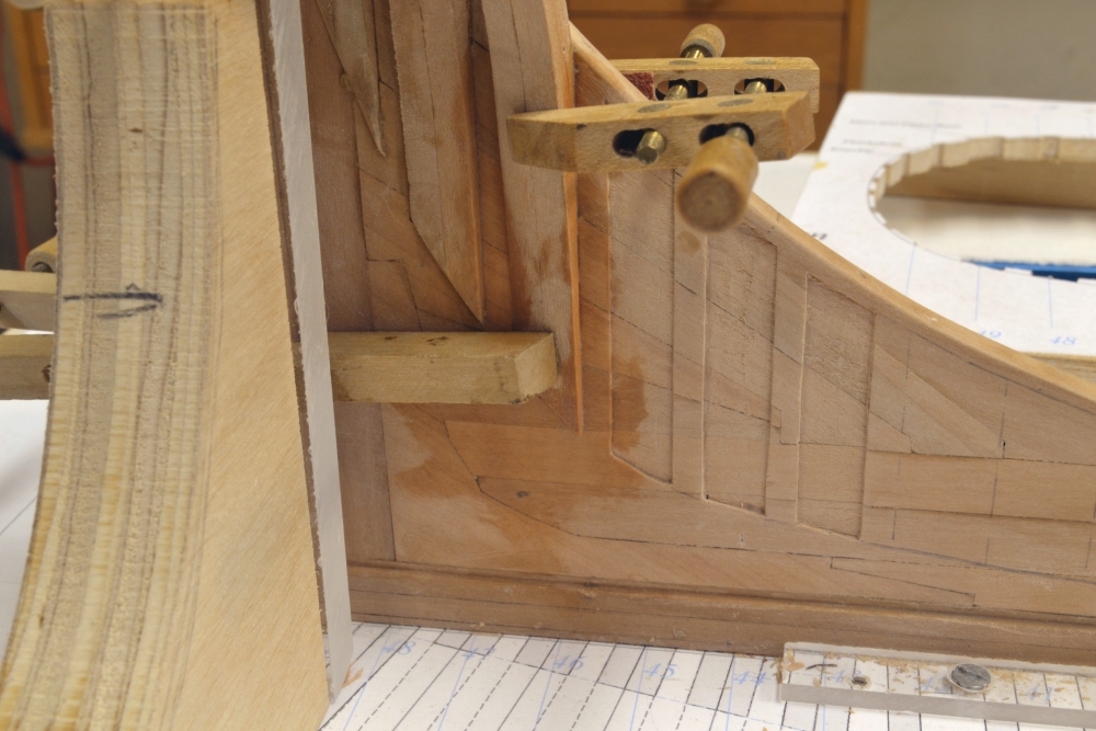
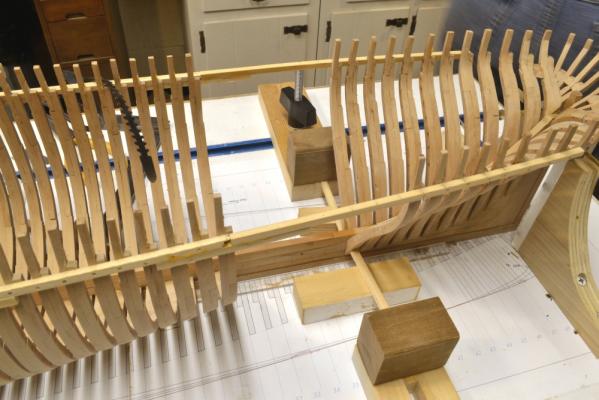
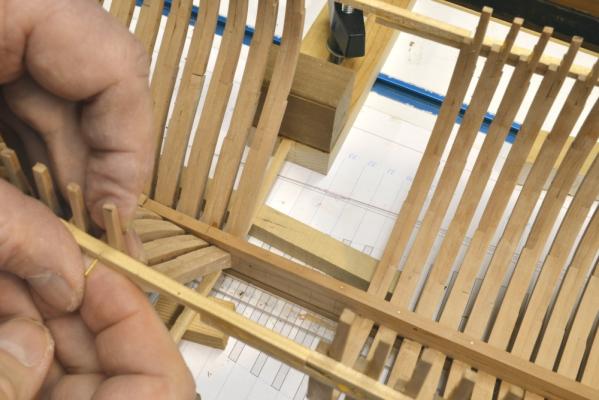
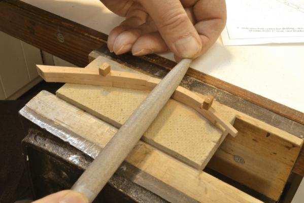
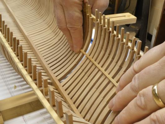
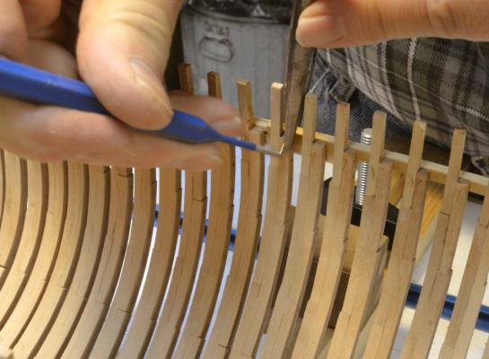
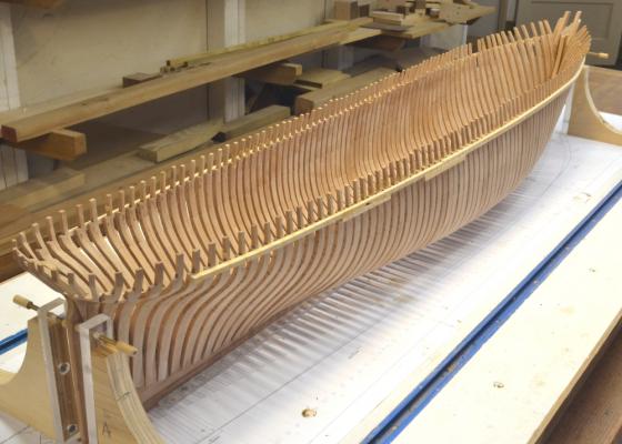
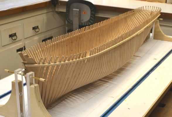
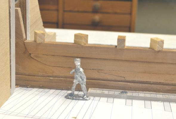
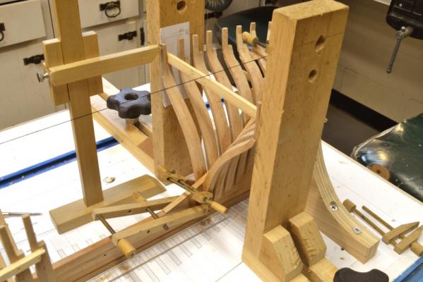
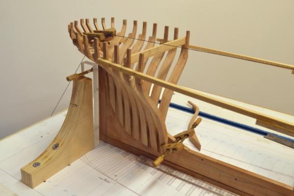
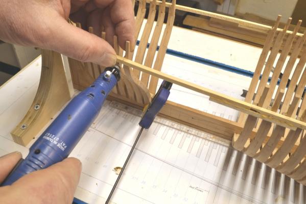
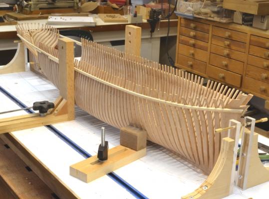
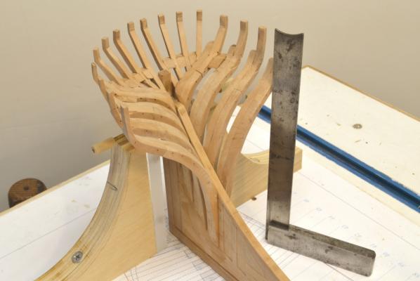
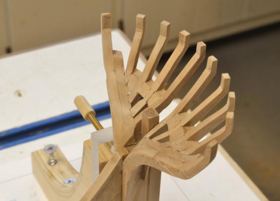
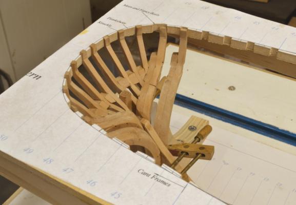
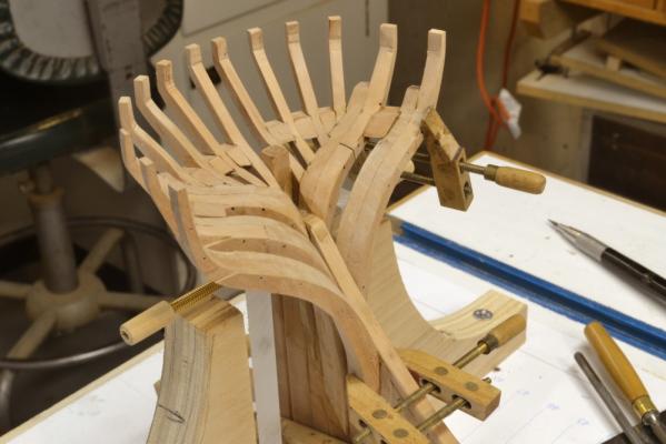
Young America - extreme clipper 1853 Part 41 – Aft Half Frames 2 Now for the final hull frames. The first picture shows two half frames being glued to opposite sides of the keelson using a different method of clamping than that used for the previous frames. As the framing moves forward the frames become more full at the base. This makes the use of screw clamps increasingly awkward. For the remaining frames the feet were held in place for the toptimber pinning and then gluing using the method shown. Wood strips are pushed to the frame and held in place by the T-track clamps. This proved much easier and, as is shown in the picture, frames on either side could be installed concurrently. The next picture shows a closer view and also a 1:72 figure – by special request. In the next picture a frame is being pinned to the ribband at the top while held against the keelson at the base. After pinning, the clamp is pulled back, glue is applied to the the joint and the clamp returned until the glue dries. The pin-indexing method of assembling frames requires that all but the toptimbers are of the same siding, in this case 12”. The upper futtocks then need to be reduced in thickness after assembly, bevelling and removal of the patterns. In the next picture this is being done with a flat file. These pieces are awkward to secure in a vise, so for this work they were pinned to a piece of Homasote board through the bolt holes. In the next picture, the fairness of the external hull is being checked before installing the last half frame on the side. This is also being done on the inside in the next picture. The frames were pre-beveled to within to within roughly 1/64” of final breadth – to the outer side of the pattern lines inboard and outboard on each face. Where there are gaps of more than about 1/64” when checked as above, the offending frame was removed and reset. There were only a few of these and resetting their height brought them within range. Final sanding will finish the job. In the next picture the last frame is being pinned to the ribband by bending over the end of the pin. The foot of the frame foot was then glued to the keelson. Installation of this last frame was a big milestone. The last two pictures show the full hull after completing the framing. There is no doubt that some of the toptimbers will need to be replaced later to precisely fair the upper rails. Hopefully the number will be few, but these small pieces are most subject to error when assembling the frames. They are indexed in assembly by only two pins and the pins are close together. One has already been removed below. The hull is now ready for final fairing. Ed


- 3,618 replies
-
- 40
-
-
- young america
- clipper
- (and 1 more)
-
Give it a try, Allan. You may find a way to make it easier. I used it on the forward section. I wasn't satisfied with all the glue joints because a tight fit smears it off and a loose fit requires clamping of both sides at once and it is hard to keep them both aligned - perhaps pins? Ed
-
Mark, there is a book by Charles Desmond, Wooden Shipbuilding. It is quite inexpensive. The pictures of wooden shipbuilding are truly amazing. Most of the photos were taken in the late 19th/early 20th centuries when the practices were still similar to earlier periods. Highly recommended. Allan, you may not have noticed, but I dropped the method of erecting the frames as a paired unit in favor of setting them individually. Much simpler and way faster - especially when using the planksheer ribband. The problem with setting as a unit is getting glue into the joint and clamping of the feet to the sides. Both have to be aligned together and to allow clamping the assembly must be flexible. I found individual setting to be a much better process. More to come on that in the next post. Ed
- 3,618 replies
-
- 1
-
-
- young america
- clipper
- (and 1 more)
-
Thanks, everyone. Be careful what you wish for, Guy. Daniel, I took this picture some time back to show the size of the keelson but never posted It, so by request, here it is. It is the only 1:72 figure I have - without cap he is a six-footer. Wrong nationality, period ans profession, but here it is. This ship was 100 ft longer than Naiad. And if its me you want, here I am resized and time transported across the Atlantic from 1797 to 1853 - a little stouter but no taller at 6'2". . Ed
- 3,618 replies
-
- 13
-
-
- young america
- clipper
- (and 1 more)
-
Don't forget the #43 drill for the 4-40 threads. Also, the rods should be sized to the major diameter before cutting the threads .112" for 4-40. A table of thread dimensions is attached that may be helpful for other sizes. Ed Screw Thread Table.pdf
-
Well, Rob, LH and RH taps and dies are expensive. For that reason there is a simpler type of screw clamp described and illustratedin Volume I. It works on a different principle and is not as versatile - but it is simpler and cjheaper to make ad will suffice in 90% of the applications. As far as understanding the Jorgensen style principle some closer study should help you get your head around it. Its similar t the turnbuckle princple which als uses RH and LH threads. Ed
-
Without opposite threads the jaws would both move in the same direction when the screw is turned - instead of opening or closing. Ed
-
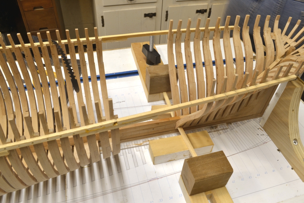
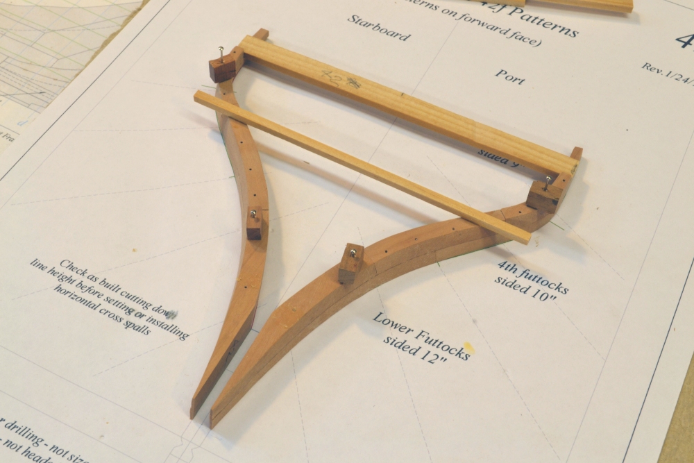
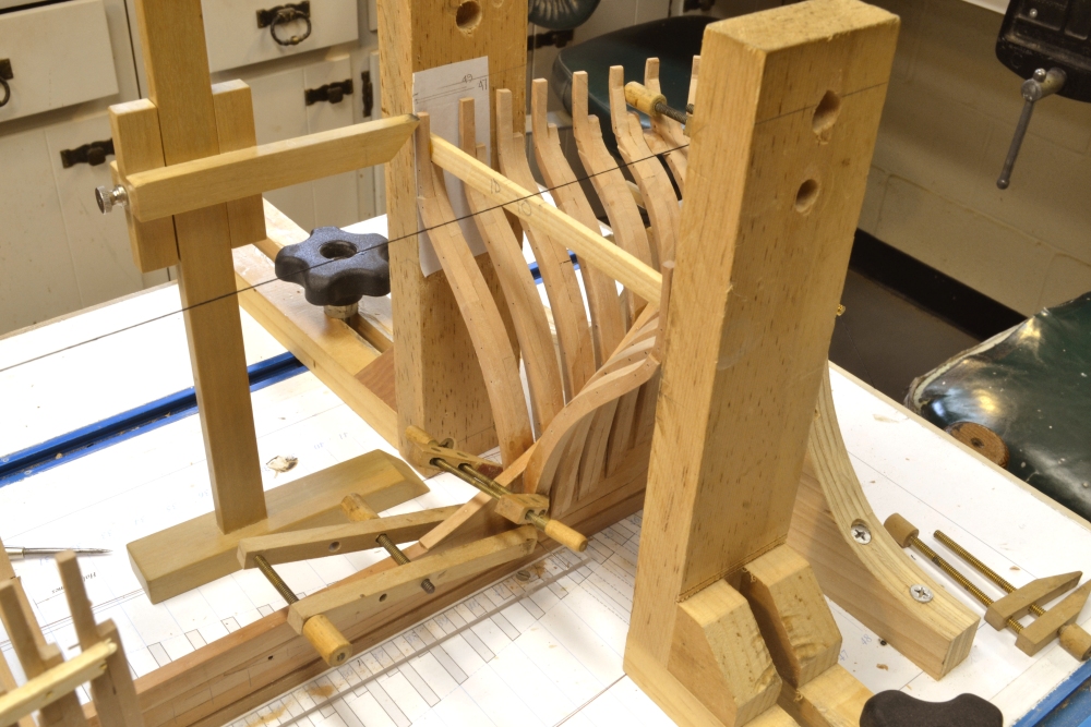
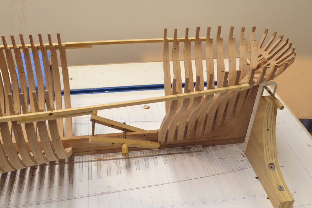
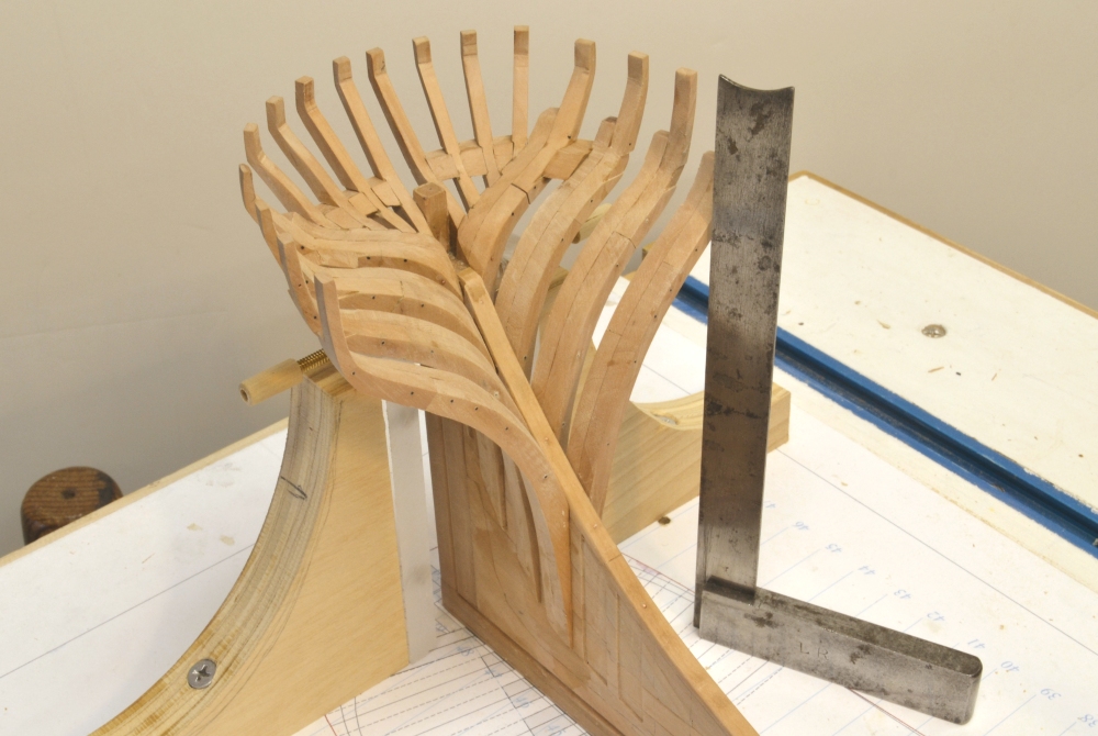
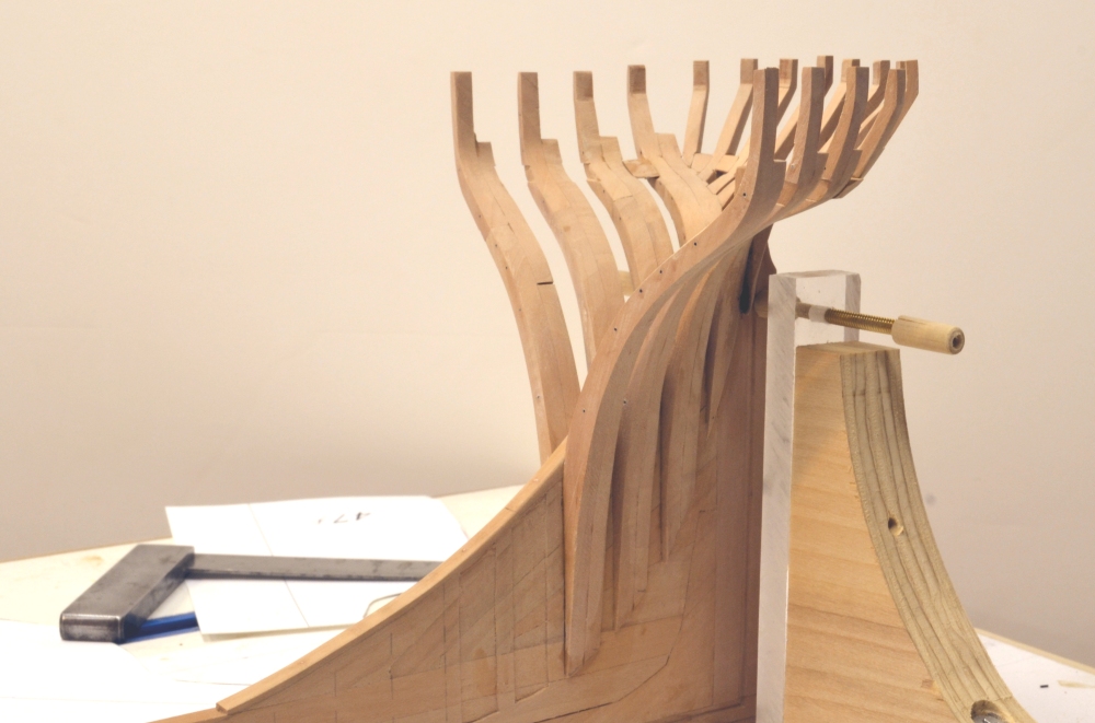
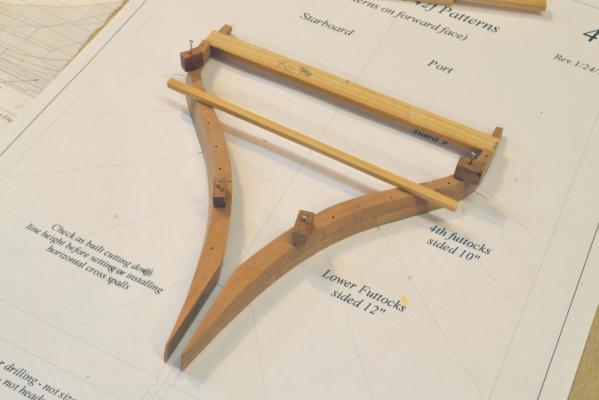
Young America - extreme clipper 1853 Part 40 – Aft Half Frames 1 As in the forward section, the aft half frames lie between the cant frames and the aftermost of the full square frames. They bolt to the vertical side of the deadwood and are square to the line of the keel. When installed they will be hard to distinguish from the full frames that rest on the keel. However when the horizontal bolts are installed the difference will be more obvious. I installed the first of these following the method used on the forward frames. As shown in the first picture these, although separate, were fabricated as a single assembly held together with temporary cross-spalls. This assembly would then be slipped over the deadwood at the correct height. The breadth at the top is held by the spalls and alignment set using the center string line. The next picture shows the erection method. The sides are contained by the two clamped squares located at the line on the base drawing. The center of the spall is marked and aligned with the string. The height on both sides is set using the vertical caliper based on heights taken from the drawing. This worked well except that gluing and accurately clamping at the deadwood was a bit involved. I soon adopted the simpler method shown in the next picture. In this method the two frame halves are installed separately. The ribbands at the planksheer were extended back into the cant frames. These ribbands are then used to set the height and breadth of the frames at the top, where they are pinned tightly through the ribband as was done for the full frames. This method roughly mimics actual shipyard practice. This turned out to be a very much simpler method with equal accuracy. In the next picture a half frame has been lightly clamped at the bottom and the frame is held so the top of the aft top member is at the top of the ribband. The ribband has been marked with the joint line of the frame for fore and aft alignment. A pin hole is being drilled through in the picture. Once pinned at the top it is an easy matter to rotate the frame to apply glue to the face, then position and clamp it in place by one of the methods shown above. This process is almost too simple. However, it does depend on an accurate ribband line. To help assure this, a spreader was inserted and pinned at frame 33, about midway in the remaining open space. Sized from the pattern for 33, this helps maintain the correct curve of the ribband breadth. This spreader and two measured strips are shown in the next picture. The strips are loose and were merely used to check the breadth at the last full frame and the last installed half frame. The last picture shows the hull at present. The remaining gap in the framing should soon be filled. Apart from the clutter of my workshop in the background, this picture gives an idea of the length of this hull – and of the L/B ratio. This is one long slim ship - roughly 240 feet long by about 43 feet broad – about 6/1. Naiad: 3.7/1. Ed


- 3,618 replies
-
- 30
-
-
- young america
- clipper
- (and 1 more)
-
Rob, the right and left hand threads on each screw allow jaws to close or open as one screw is turned. The jaws can then be adjusted independently at each end. With rotating cross rods in the jaws threaded appropriately for the threaded rods, very flexible clamping positions can be set. These are miniature versions of the popular "Jorgensen" style clamps widely used in woodworking. They take some getting used to, but once you get the hang of it, they become treasured tools. I have sizes up to 12" long, but these are not often used in model work Ed.
-
Nice work, Salvatore! Some interesting new types there as well. Ed
-
Richard, You are right. The flexible clamps are a bit of a project in themselves. Compared to the easier ones, they are almost a nicety. Taps and dies are available as either RH or LH, so be sure to get both. I used brass and would suggest you use the same. The darkened glue should last as long as the normal glue. You do not need a lot of pigment to get the dark color when it dries. Be sure to slurry the pigment in water to eliminate all lumps before adding the glue. Then mix very thoroughly. Good luck. Ed
-
Thanks, Mark, Walt, Rudolf and all those who "liked" the last post. Walt, I think practices on clippers varied. I believe below the wale it was general practice to install diminishing strakes that would blend the plank thicknesses. At the top of the wale, I believe it was common to chamfer the top strake of the wale down to the thinner waist planking below the planksheer raIL. I have a bit more research to do before making a drawing, but when I have a cross section I will post it. Ed
-
Thank you all for these comments. I don't know, Greg. Sounds extreme. Walt, I do not have any planking cross sections, at least not yet. I work on sort of a just-in-time approach with the drawings and have not yet gotten to the planking. there are some cross sections in Crothers book, but I try (usually) not to post copyrighted material. Ed
-
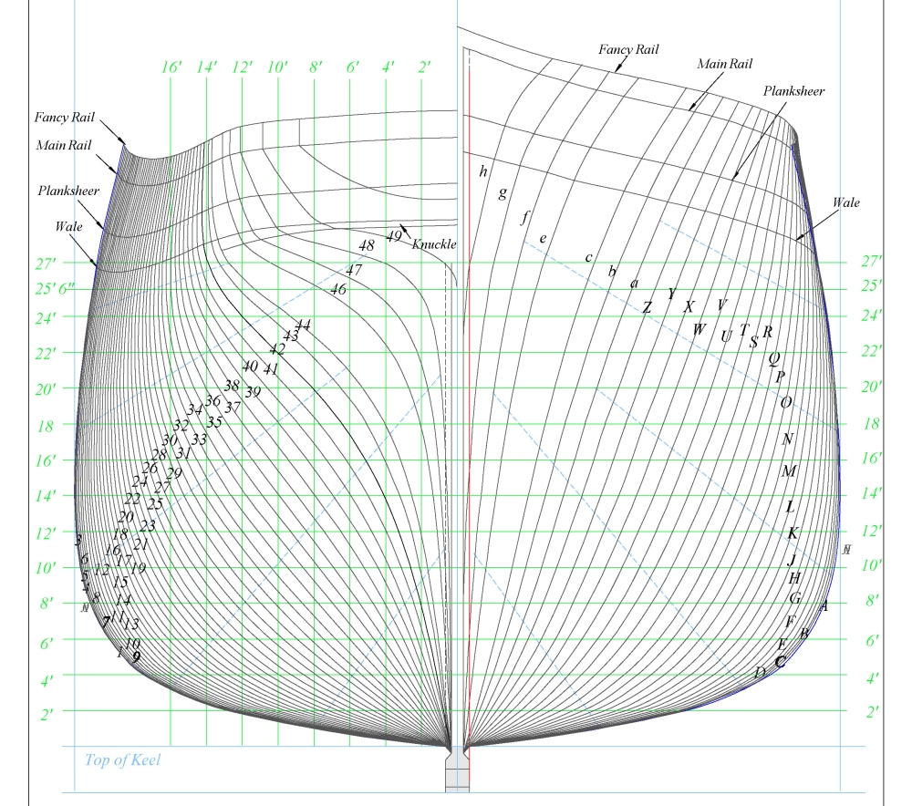
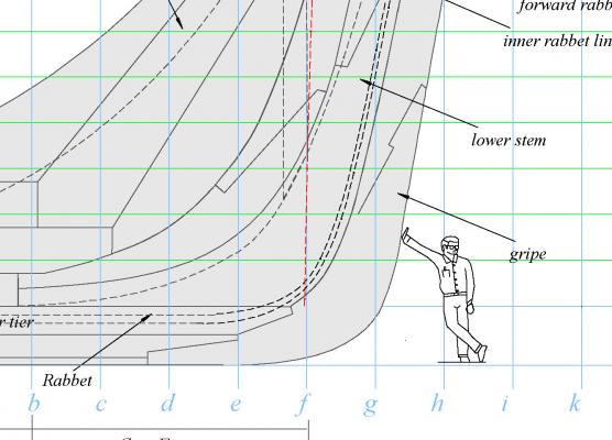
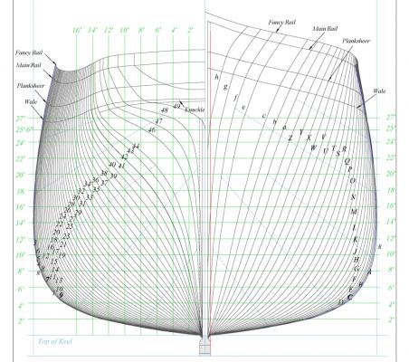
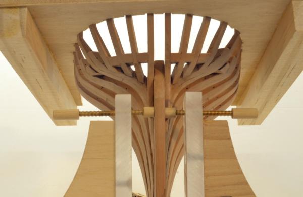
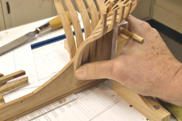
Young America - extreme clipper 1853 Part 39 – Aft Cant Frames Clipper Ship Note: The longitudinal hull lines on the American clippers introduced some new terms and redefined some old ones. Furthermore, the names of some these lines differed between builders. Young America’s table of offsets was generally similar to most of the breed. It included the following longitudinal lines. The wale delineated the top of the band of thick planking also called the wale. As in earlier ships, the curve of this line defined the sweeping fore and aft sheer of the ship. In clippers, unlike RN 18C ships, the line was higher forward and lower at the stern. In Young America’s case the band of heavy wale planking extended downward about ten feet almost to the turn of the bilge. The wale line was high - usually two feet or so below the line above – the planksheer. The planksheer defined the underside of the rail that capped and sealed off the main inboard and outboard planking. It was essentially parallel and at the level of the top of the main weatherdeck waterway. The planksheer rail was penetrated by toptimbers of the frames that ran up to a higher level at the tops of the sides. The main rail line defined the underside of the main rail. It was about three feet above the planksheer and about 18 inches below the rail that capped the tops of the toptimbers. This last line was called, in the case of Young America, the fancy rail. In other ships it was known as the monkey rail. It defined the top of the side from stem to stern. Young America’s fancy rail is at the level of the poop deck aft and slightly higher than the topgallant forecastle deck at the bow. Another open rail was constructed above the fancy rail along the poop deck to help keep the crew out of the drink. On Young America this was a wood rail on turned brass stanchions. All of these rail lines were, for the most part, parallel curves. Below is a body plan with the lines marked. So, back to the model. The first picture shows cant frames 48 forward to 45 installed. The square is positioned for checking the cant of frame 45 on the port side – from the base drawing. The next picture shows a different view of the assembly at the same stage. The “feet” of the cant frames were left a bit on the heavy side and will be sanded back fair to the bearding line later – probably before bolting. Otherwise the frames are pretty well beveled to their final shapes. Two more pairs to go. In the next picture the template has been placed over the tops of the frames at this stage to check position. The next picture is a view from under the stern at the same stage. The space between the two central stern timbers will later be fitted with a chock shaped to the helm port. In the next picture, frame 44 on the port side is being held in place during fitting. In the next picture this frame has been installed and frame 43 on the starboard side is being glued in place. The last picture shows all of the aft cant frames installed before the clamps on the last were removed. The 12 aft half-frames - 42 to 31 - will now be made and installed to complete the frame installation. Ed


- 3,618 replies
-
- 34
-
-
- young america
- clipper
- (and 1 more)
-
Thank you, druxey. I thought the term "fancy rail" might provoke comment. I have only seen this term used on Webb's tables of offsets. Others use the term "monkey rail." Perhaps I will include some explanation of these rails in the next part, since the naming is different than our more usual RN 18C. Ed
-
Maury, the jig actually slips very easily over the timbers from below. I do not need the height settings anymore, so I can just slip it on and off the set the frame spacing and beadth, but I am mostly relying on templates now that the aft timbers are in place. Ed
-
Young America - extreme clipper 1853 Part 38 – Stern Timbering 2 After setting the eight stern timbers, chocks were installed between them in scores at the “knuckle” where the timbers change direction upwards. This knuckle gradually smoothes out into a curve in the cant frames section. The assembly has not been sanded at this stage. Some sanding has been done in the next picture, which shows all of chocks installed. With this work complete, the cant framing was continued forward. The next picture shows the method used for final beveling the frames before setting. The first step in this process was to rough shape the frames on the disk and spindle sander. Fine cut rasps and a #0 cut half round file were used to trim the frames right back to the lines on each face of the patterns on each side. All this work could be done by hand, but the power tools save time. In the next picture frame 47 has been installed on the starboard side and its port counterpart is being fitted on the port side using a template. These templates were very easy to make by creating a view of the three profiles on the CAD worksheet for the cant frame. They were then printed on heavy presentation paper and cut out with a knife. This eliminated pasting to heavier stock and cutting on the scroll saw. That was the method I had used previously. The next picture shows the gluing up of the above frame. The stern template and two clamps hold the frame in position. In the next picture the next frame, #46 is clamped and glued on the starboard side. The next picture shows a closeup of the foot of the frame and the clamping. The wet areas on the wood are from washing off the excess glue. In the next picture a knuckle chock has been installed between frames 48 and 47 on the starboard side and its counterpart is being glued in on the port side. And so it goes. Ed


- 3,618 replies
-
- 34
-
-
- young america
- clipper
- (and 1 more)
-
Richard, I personally would not use Mylar on top of the shipway. You will need to make precise pencil marks on the paper base for setting the fore and aft location of the gantry or for other uses during the build. You will see these methods described in various chapters. I used a Krylon product called matte Preserve-it on the paper. Its a spray coating that can be applied after pasting Dwg. 2B to the board. It can be marked with pencil, like a very sharp pointed 2h or 3h. I suppose if you used a thick plastic base sheet you could scribe lines instead. Just make sure the thickness of the sheet doesn't effect your vertical measurements. But why bother? the pasted 2B is a write-off anyway. Yes, I noted the shipping cost. I assume it is the same for various lengths. Sounds like you have a solution. Thickness may be important so you don't get refraction when you make measurements. I took some measurements through a 10 mil binder cover plastic sheet and it was OK. Be careful with those markers. If you pick some up on your fingers from the film it could stain the work. Forgive me. I'm very cautious about that - no water soluble colored pencils, no fine line felt tips, no soluble inks, etc. allowed in the shop. Ed
-
Here is a link for 10 mil Mylar that may be even better. http://www.amazon.com/Mylar-Stencil-Material-Blank-Mylar-24-stock-priced-medium-duty/dp/B008FPARI2/ref=sr_1_1?ie=UTF8&qid=1390406080&sr=8-1&keywords=10+mil+stencilease+roll
-
You are welcome, Richard. I included the extra plan 2B for the shipway for just that reason. I built the original Naiad with just one copy of the plan glued to he shipway with Krylon spray adhesive. My drawing was on lower quality paper but held up very well. I did have to change out one part, (my large prints were all in 11 X 17 pieces taped together) because I was making revisions and additions to the drawings as the work progressed. To help protect the drawing on the shipway you may wish to spray it with a protective coating. I would use someting that dries matte and can be marked with a pencil, since some of that marking is required along the way. It will also make cleaning up glue blobs easier. Since all of the ncessary patterns and templates are on the CD and can be printed multiple times as needed, there is no need to do any tracing on or defacing of the large drawings. In some cases copies of parts of the large drawings were included on the CD to use as templates. The large drawings are therefore only needed for measurements. Measurements are usually taken with dividers or calipers. Calipers are better in the sense that they do not have the tendency to prick the drawings - if you are interested in preserving them. I think protecting drawings on the bench (or if you wish, on the wall)should be quite easy using clear Mylar polyester film. Here is a link where it can be purchased in 24" width on a roll by the foot. I have not tried this, but its 7.5 mil thickness should allow dimensions to be easily picked off. I may try this on my Young America drawings as a test. http://www.amazon.com/Mylar-Stencil-Material-Blank-Mylar-24-stock-priced-foot-7-5/dp/B008FPASTK/ref=sr_1_1?s=office-products&ie=UTF8&qid=1390405076&sr=1-1&keywords=mylar Ed
-
Thanks for your understanding, Gary. I look forward to your questions and progress. I suggest a build log. Ed
-
Rob, thank you for your input. Can I assume you have purchased the book and are familiar with the extent of the drawings and supplementary CD contents? I think you would find it more than adequate to build the model without having to make copies of the large drawings. If you have not bought the book, I would be glad to enumerate the contents of the CD that is provided in addition to the 15 large drawings. Multiple prints of the extensive CD content can of course be made. I fully understand and accept that I cannot control copying of the book contents. Judgements on that are in the hands of purchasers. I am not in the business of selling drawings. If I were, they would not have been included in the book and would have sold separately at several multiples of the book price in order to make any profit. Ed