HOLIDAY DONATION DRIVE - SUPPORT MSW - DO YOUR PART TO KEEP THIS GREAT FORUM GOING! (83 donations so far out of 49,000 members - C'mon guys!)
×


EdT
-
Posts
2,214 -
Joined
-
Last visited
Content Type
Profiles
Forums
Gallery
Events
Everything posted by EdT
-
Thank you, Grant and Mauricio. It appears that in the final book production process the last paragraph and part of the preceding paragraph of Chapter 28 was somehow left out. Sorry for this. The last wo paragraphs of Chapter 28. p 102 should read. "You may wish to forgo the complexities described above in favor of simpler joints. The quality of your models will not suffer simplification in these minor details. However, I hope that the process described above will entice you to construct these authentically. When the lower deck hatchways are installed, the ladders to the orlop level platforms can be added. In keeping with our sequence and chapter arrangement, other lower decks details, partitions for example, will be covered with the upper deck framing in Chapter 31." Sorry for any inconvenience. Ed
-
Thank you Gary and Jan. Jan, the extreme designation was discussed in, I believe, the first post. The term "extreme" was applied to clipper ships that were designed purely for speed, without compromising for other considerations like cargo space. The extreme designs came about at a time when fast passage times were of paramount importance to shippers - because of the high demand for the freshest tea leaves from China to both the US and England, because of the extremely high profits to be obtained on goods bound for California during the gold rush, and later from the Australian gold rush. The extreme designs featured very sleek lies with sharp entry and run aft. Length to breadth ratios were very high. In the early years high deadrise of the midship floors were prominent. Sail plans were extremely lofty - often to the point of oversparring and/or fragility of the upper spars. They were more like Formula I cars than the family sedan. They were intended to be raced. The period was short lived as the California prices cooled off and the Suez Canal made steam more viable for the eastern trades. This created a glut of fast clipper ships. About 1855 the designs of ships began to trend back toward increased cargo space and the clippers of this later type were referred to as "medium". There were no hard and fast classification rules, but the builders and the press made the designations that have generally been accepted by time. Ed
-
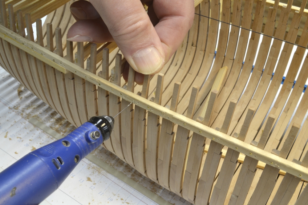
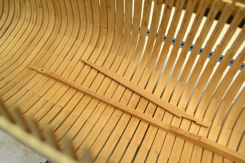
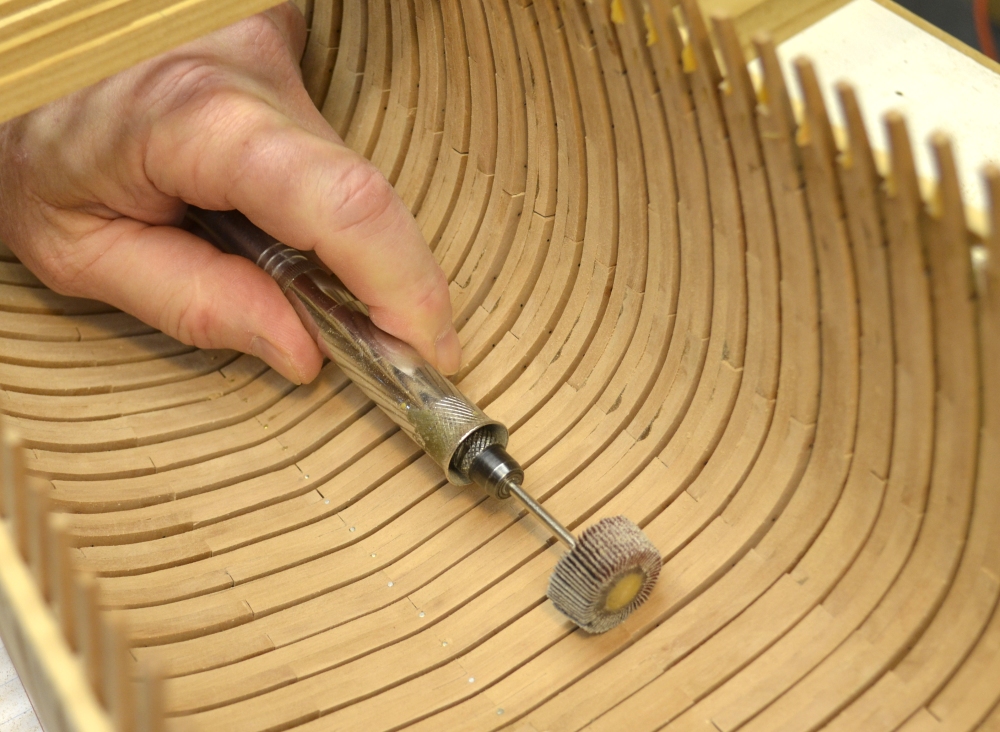
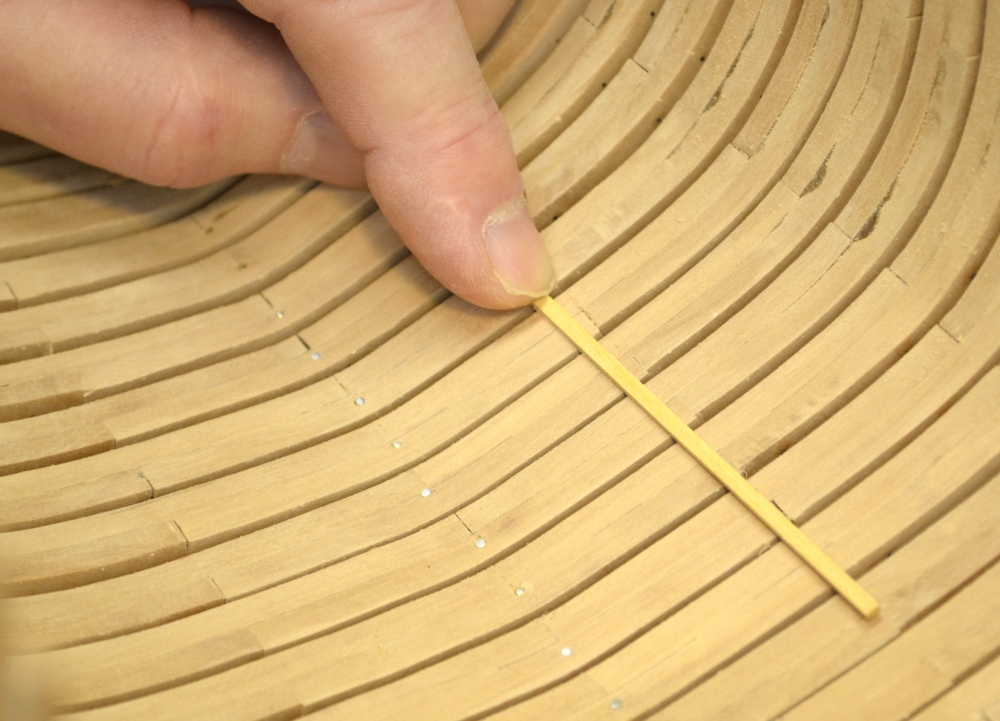
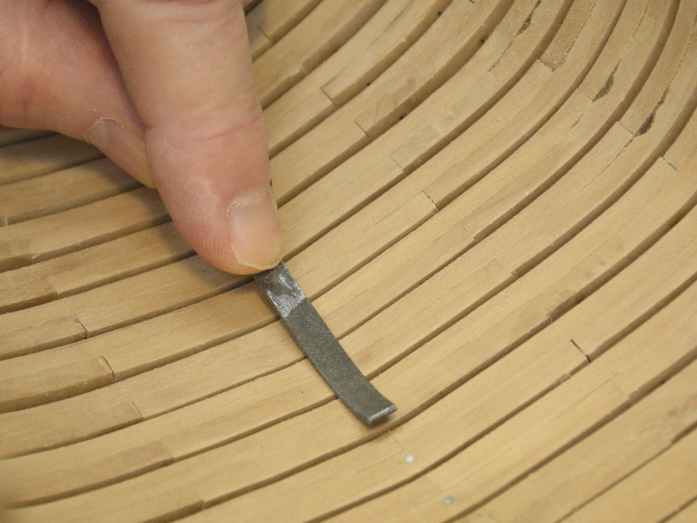
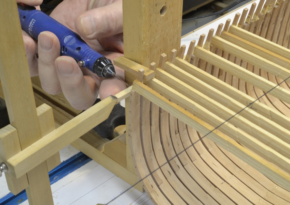
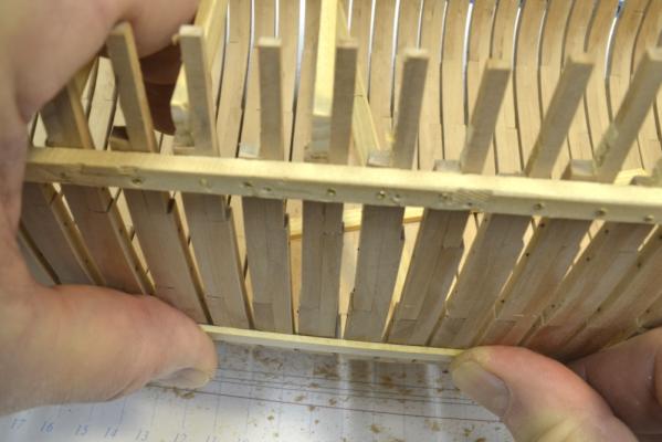
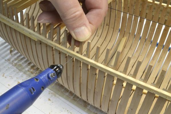
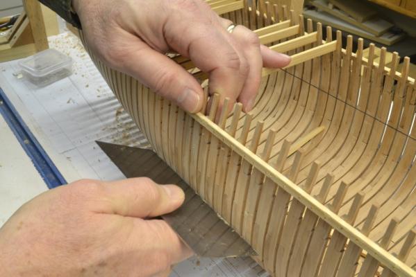
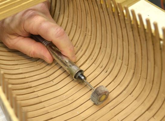
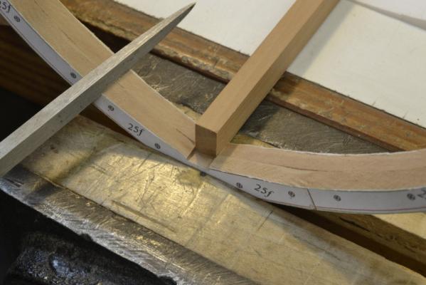
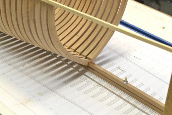
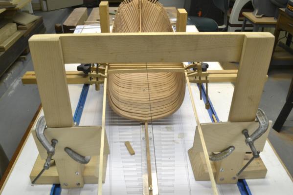
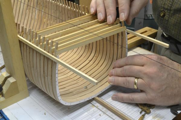
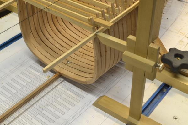
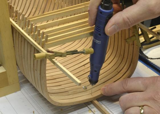
Young America - extreme clipper 1853 Part 32 – Frame Alignment/Fairing The aft half and cant frames are bolted to the sides of the keelson/deadwood, so these cannot be installed until that assembly is in place. The keelson comes first, but to install that it is necessary to have the inboard faces of at least the floor timbers well faired. The first step was to check and, if necessary, adjust the alignment of the installed square frames. The first picture shows this being done with a batten. It can be seen in this picture that there is a gap over the center frame. To correct this, the pin holding the top of the frame to the ribband was removed and the frame pushed downward slightly on this side to adjust it outward. A new pinhole was drilled while holding the corrected position – as shown in the next photo. All the frames aft of 0, on both sides were checked and five or six were adjusted in this way before proceeding with the next steps. The outsides of the frames between the floor heads and the ribbands were then faired as shown in the next picture. In this picture a cabinet scraper is being used on this part of the hull. This tool has some advantages for this. First, it works with the grain so sanding out cross grain scratches is reduced. More importantly, it allows you to easily see when the frames have been leveled out – or which frames are out of line. Pre beveling of the frames before setting greatly reduces the amount of work in this step. No cross grain sanding was necessary in these areas. With the outside of the frames faired out, the floors could be faired to receive the keelson. This fairing was done out to the floor heads. A rotary tool with a flapper wheel as shown in the next picture was used for some of this, so taking this fairing out at least to the floor heads is advisable before installing the keelson. This tool also has the advantage that it sands with the grain. In the next picture the fairness is being checked at the floor heads. The frames above the floor heads are still a bit rough. Finally the joint face with the keelson is leveled out as shown below. All this work was done in the forebody earlier to install the forward part of the keelson and the forward deadwood. The next picture shows the first section of the lower tier of the aft keelson installed. Copper wire bolts through every other frame have been inserted through into the keel and epoxied. The frames are now well secured. The next section of the upper keelson tier is ready to be installed. The dark areas are still damp from washing off the epoxy for the bolts with isopropanol. The central model support bolt hole comes through the aft end of the keelson section in this picture. The next task will be to cut a mortise around that hole to insert a nut – next time. Ed


- 3,618 replies
-
- 29
-

-
- young america
- clipper
- (and 1 more)
-
I have ordered a number of books from Ancre over he past several years. The service, packaging and condition of the books has been excellent on all occasions. Ed
-
Naiad Frigate Volume I Addenda Attached is a pdf of the compiled Addenda 1 to 4, including the revised patterns etc. as required. Some of this includes corrections and some of the information is additional and may be useful. As additions are needed, I will update this document and post it so that all addenda will be available in one posting. Vol 1 Addenda.pdf Ed
-
Thank you, Richard. I will give some thought to your request. The disadvantage of adding updates as edits to a single post is that there would be no email notifications of the changes. The advantage of posting as separate posts is that everyone gets notified. Perhaps there is another way. Ed
-
The Naiad Frigate - Addendum 4 There is a discrepancy between the configuration of Frame OA as shown on the original Naiad draft and the way it is shown on Drawing 3 and on the pattern on the CD. Frame OA is shown butted against frame OF over its full height. In fact the upper futtocks of Frame OA should be set 2" aft of the joint line. Attached is a revised pdf for the OA pattern and another showing the correct configuration for frame O on Drawing 3. Thank you, Albert, for pointing out this difference. Ed 03 Naiad 60 Hull Framing Elevation Frame O.pdf Naiad 60 Pattern OA.pdf
-
HMS Naiad 1797 by albert - FINISHED - 1/48
EdT replied to albert's topic in - Build logs for subjects built 1751 - 1800
Lovely work, Albert. She looks bellesimo! Ed -
Merry Christmas, Gary. I think the deck looks great. I am sure those decks were pretty white after holystoning everyday with salt water. Ed
-
Not a problem, Salvatore - and thank you for he holiday greeting. I am always interested in comments on the book and addressin any issues wit the content. I will await your answer. Have a safe trip. Ed
-
Salvatore, Thanks for your note. I checked all three of the angles you mentioned on the original CAD worksheets and all three appear to be correct. I also checked the three frames using a protractor on drawing 2 and that also showed the angles to be correct. Please tell me the method you are using to measure the angles. That may help me understand the differences you are getting. I will describe how these angles were determined. Each cant frame is shown in plan as a CAD object on Drawing 2. Each of these objects has properties that describe key parameters. One of these is the angle of the object,in this case the angle of the cant frame to the side of the deadwood. I used those angles to calculate the bevel angles for the patterns. These angles should be very accurate and in fact I found this to be so when using them to build the model. Cheers, Ed
-
Thanks, everyone - for the comments and he "likes". I have been trying to stay out of the workshop because I have so many chores to do over the next few days, but I may sneak in there to cut a few keelson scarphs when someone isn't looking. Again, happiest of holiday seasons to everyone. Ed
- 3,618 replies
-
- 1
-
-
- young america
- clipper
- (and 1 more)
-
Thanks for this comment Salvatore. It reinforces my own view. Digital calipers are the answer for small measurements of precise dimensions and most calipers available today support inches or metric. For larger dimensions, fractions of mm are less important so a metric ruler or an inch ruler graduated in tenths does the job with either the conversion chart or a simple calculation. Feet-inches-fractions conversions can be a bother and I actually started putting decimal inches on all the drawings for easier digital conversion, but that still leaves the feet-inch issue. I did not want to put all the dimensions, especially the large one in just decimal inches. In the end, no matter what system, there is still some conversion to be done and after doing it a few times it becomes second nature. Ed
-
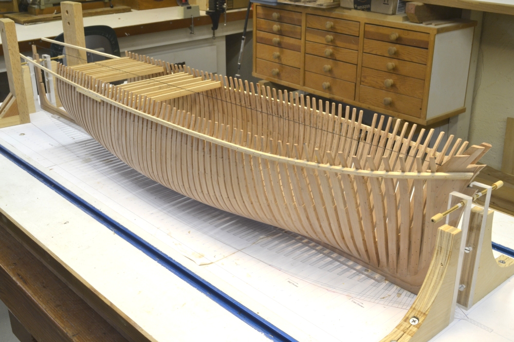
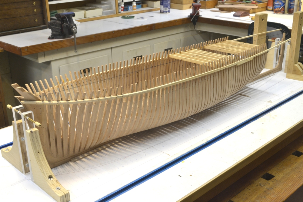
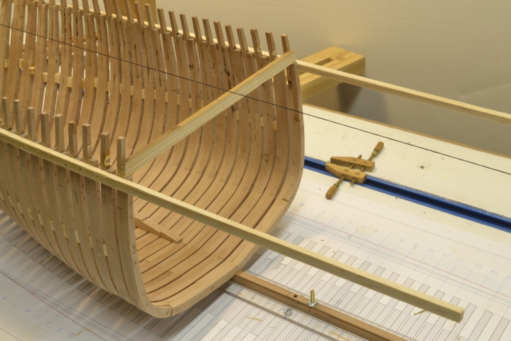
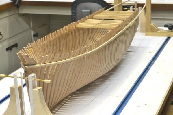
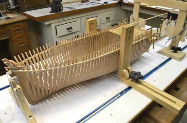
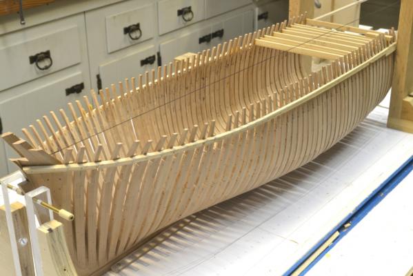
Young America - extreme clipper 1853 Part 31 – Aft Square Frames 3 The installation of the remaing full square frames has now been completed – back through frame 29. Starting with frame 21, the cutting down line begins to rise. This is the line of the inboard faces of the frames adjacent to the keelson. However, unlike the 18thC RN ships, the keelson remains straight and horizontal all the way back to the stern post knee in these ships. So the tops of the full frames need to be notched as shown in the first picture – to accept the straight keelson. This notching of the last several full frames increases the thickness – the molded breadth – of the lower part of the frames so that when the first half frame is reached there will be enough depth for that frame to be secured with horizontal bolts to the keelson/deadwood. That increased depth needs to be approached in a fair line so the inboard planking will lie flat on the frames with no steps up. The next picture shows the last of the full frames installed – back to the filler piece atop the keel. The remaining aft frames will be bolted on the face of this filler and the keelson/deadwood with horizontal bolts – as was done at the bow. This picture shows the gradually increasing height of the cutting down line over the last half-dozen or so frames. The straight lower keelson will fit into the notches. The remaining three pictures show the framed hull at this stage – with the clutter of tools and debris removed.. Another foot or so of hull framing remains to be done – almost back to the ends of the two temporary ribbands. The last picture gives some indication of the fairing of the hull at this stage. Only the pre-bevelling of the individual frames has been done so far. The frames appear to be fair with about 1/64”. Some adjustment in alignment of a few frames may reduce that further, leaving only a small amount of final sanding. The next steps will be to refine the fairing of the floors on the inboard side prior to installing the remainder of the keelson. It is much easier to do this before the keelson is installed. With the two levels of the keelson installed, .the deadwood can be constructed. This will allow the half and cant frames to be set. Since this will be the last post before Christmas, I will wish everyone the happiest of holidays and a great new year. Thanks for following these postings. Ed


- 3,618 replies
-
- 30
-
-
- young america
- clipper
- (and 1 more)
-
I had a question today asking whether metric dimensions were included on the drawings in the books. All of the dimensions on the drawings and details sheets are actual real world dimensions - that is, the dimensions of the actual ship. As with the original English ship, all are in feet and inches. I have not reduced those to model size on any of the drawings. In the books, I recommend taking larger dimensions directly from the drawings with calipers or dividers. For smaller dimensions like scantlings or for smaller assemblies and parts like the capstan, jeer bits, etc. I recommend using a conversion table then using digital calipers, micrometer or sometimes a decimal ruler to size the model parts. A 1:60 conversion chart is included on the CD that shows conversions from actual inches to 1:60 inches for dimensions up to 72 actual inches. The drawings in the book for tools and fixtures have inch dimensions, however most of these are 1:1 scale, so sizes can be measured directly. To assist those with metric measuring tools, I am attaching a metric version of the 1:60 conversion chart in pdf form. 1to60 Inch to mm Conversions.pdf Ed
-
ancre LE BONHOMME RICHARD by Jeronimo - FINISHED
EdT replied to Jeronimo's topic in - Build logs for subjects built 1751 - 1800
Absolutely beautiful work Karl. Ed- 662 replies
-
- 2
-
-
- bonhomme richard
- frigate
- (and 1 more)
-
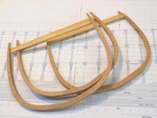
Yes, Daniel, the framing work is going faster than I thought. I attribute this to the pin-indexed patterns and assembly process. I assembled the parts of three frame pairs in less than an hour yesterday. Also, the frame pairs are simpler on this ship than on the 18C RN ships. End of the year? I doubt it. Ed
-
Thank you, Alexi. I probably should have mentioned that missing toptimber, since it does catch your eye. I removed it for some reason - can't recall now. It may have been badly misaligned or damaged. I will replace it later. Also, I am sure there will be others that will require replacement when I get to their final fairing and alignment. Ed
-
Thank you, Walt. I believe the simple style of clamp is the most practical of the two types. They are easy and inexpensive to make and so they support the golden rule of clamps, i.e. you can never have enough. They are not as fancy, but they do most of the things the more complicated flexible type do. Best holiday wishes to you as well. Ed
-
Thanks, everyone for your comments and the 17 "likes" on the last post. Harvey, the tool is a Wecheer Rotary detail carver by Flexcut. You're right. It is very much easier to manage for small holes and carving than the larger more powerful Dremel tools. They are also inexpensive. They make other models and related tools as well. I use this tool all the time for hand drilling. The tool also takes Dremel collets. Here is a link: http://www.amazon.com/Flexcut-ROTARY-DETAIL-CARVER/dp/B0002IXNK4/ref=sr_1_2?ie=UTF8&qid=1386766604&sr=8-2&keywords=Wecheer Ed
- 3,618 replies
-
- 2
-
-
- young america
- clipper
- (and 1 more)
-
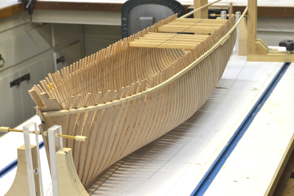
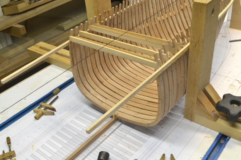
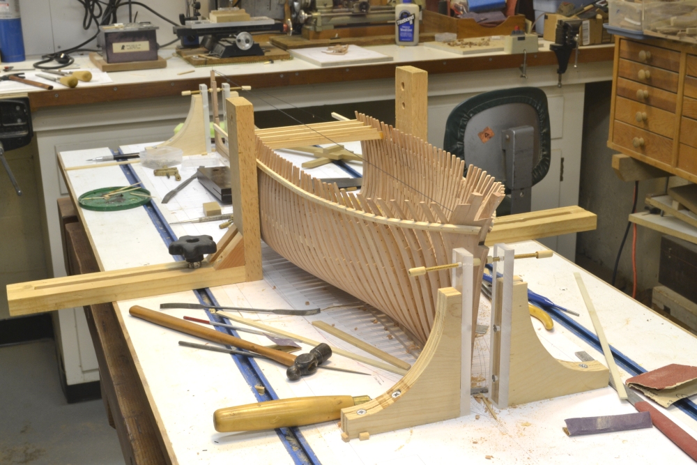
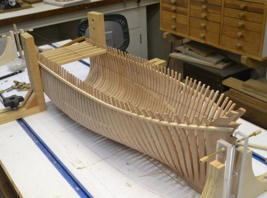
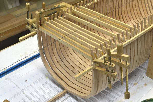
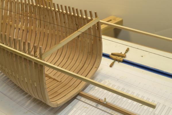
Young America - extreme clipper 1853 Part 30 – Aft Square Frames 2 At this stage the first 15 full frames aft of 0 have been set. The first picture shows frames 16, 17 and 18, right after inserting their bolts. These are ready to be installed. The next picture shows the hole being drilled for a pin on the port side of frame 16. A bent pin in this hole will secure the top on this side of the frame to the ribband strip. I mentioned earlier that a wood block is used to space the frame and the caliper to set the height of the ribband to the bottom of the planksheer rail. That rail will be added much later. The next picture was taken after frames 16 and 17 were erected. At this stage the ends of the temporary ribbands were reached. The next picture shows work to extend the ribbands. Setting frames using the ribbands has been a major time saver and helped get the frames into faired lines. Connecting strips are being glued to the bottom of the existing ribbands. The next picture shows the ribband extensions being glued on. The “gantry” is being used to hold clamped guides the set the height and breadth of the ribbands at that position along the hull. The gantry can be moved and the guides set at any given position. The next picture shows another view of the hull with the extended ribbands. In the last picture frame 18 has been installed and pinned to the ribband extensions. The length of the hull – and the eventual size of the model are starting to become apparent. It is really long and slender. By way of comparison, Naiad was 147 feet long with a breadth of roughly 39 feet – an L/D ratio of roughly 3.7 to 1. Young America had a length of 240 feet and a breadth of 43 feet – an L/D ratio of 5.6 to 1. There are now 11 more full frames to install. 19, 20 and 21 are in fabrication. 22, 23 and 24 have been lofted. After installing the last full frame - number 29 - the keelson and aft deadwood assemblies will be completed to prepare for the half and cant frames. Ed

- 3,618 replies
-
- 31
-
-
- young america
- clipper
- (and 1 more)
-
Richard, I would suggest getting a copy of Steel's Vade Mecum for the Shipbuilder. It has much of the same information and is very useful. The tables of scantlings do not include as many classes of ships, but are otherwise very complete. If your class of ship is not listed you might try getting a copy of a contract for the ship or the class from the National Maritime Museum in London. The Vade Mecum can be downloaded free t: http://books.google.com/books/about/The_shipwright_s_vade_mecum_by_D_Steel.html?id=pjcDAAAAQAAJ I wish I could tell you how to navigate to Ships Contracts at the NMM website, but although I have succeeded in doing it, a least once, I cannot repeat the process. Perhaps someone out there can describe how to do it. Ed
-
Fascinating method, Micheal. Ed
-
Richard The work by Steel that I have listed in the bibliographies of Volumes I and II, is Steel's Naval Architecture, not his work on masting and rigging. I may have listed Masting and Rigging, but the work I generally refer to is Naval Architecture. Ed
-
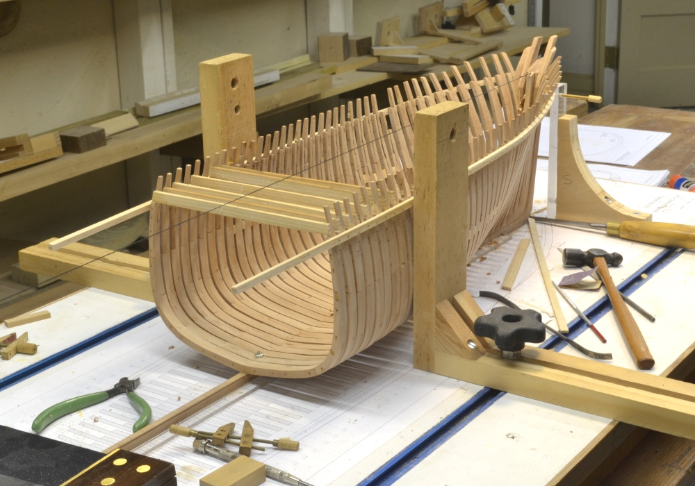
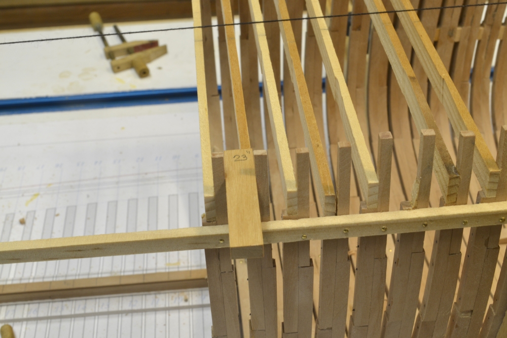
Young America - extreme clipper 1853 Part 29 – Aft Square Frames Framing aft of frame 0 has been proceeding well over the past few days. I have adopted a new alignment method that I will describe in this part. The first picture shows frame 1 installed. Instead of using temporary wood chocks to hold frame alignment and spacing, I decided to try and use the temporary ribbands. These are at the height of the planksheer. I left them long, anticipating this. The next picture shows more frames installed. The heights of the cross-spalls in this picture are irregular because they are set down on the aft top timbers and these have been left slightly long for cutting down later. Each spall sets the breadth of the frame accurately, however, and is center marked. The next picture shows another view of the overall hull, and displays the normal cluttered state of the shipyard. Another view from aft. In the next picture, an assembled frame – frame 9 – with its patterns still on, is being test fit after beveling. All of these frames are being pre-beveled to the lines on the patterns. The next step is to remove the patterns and downsize the sidings of the upper timbers. This cannot be done until the frames are beveled and the patterns removed. In the next picture the frame has been clamped to the ribbands at the top and positioned accurately with its floor centered down on the keel. The maximum breadth of the frame is then checked by squaring up from the base drawing. A hole for the model bolt is being drilled. Because of interference with the spall, the hole will be angled aft slightly. A short pin is then inserted to hold the position. The clamps are then removed and the frame lifted slightly to spread glue on the keel. The pin is then driven home to secure the joint. Before the glue has set the toptimbers are aligned using the spacer block in the next picture. The caliper is set from the drawing to the height of the bottom of the planksheer rail so that will be at the correct height at each frame.. The next picture shows a closeup of the spacer block. Its width has been sized to 23” – the spacing between frame lines in the area (32”) minus the siding of the toptimber (9”) A pinhole has been drilled through the toptimber and the temporary pin bent over to hold the frame tight to the ribband. The half breadth of the frame is then rechecked using a square from the the line on the base drawing. This method is not only much faster and less messy than using the spacers, but pulls the frames into a fair line at the top. If made to the pattern and beveled accurately to the profile lines, the frames should be pretty well faired when erected. So far, that is the case. We will see how this holds up as the bevels increase with each new frame going aft. Ed


- 3,618 replies
-
- 25
-
-
- young america
- clipper
- (and 1 more)