HOLIDAY DONATION DRIVE - SUPPORT MSW - DO YOUR PART TO KEEP THIS GREAT FORUM GOING! (Only 13 donations so far - C'mon guys!)
×


EdT
-
Posts
2,214 -
Joined
-
Last visited
Content Type
Profiles
Forums
Gallery
Events
Everything posted by EdT
-
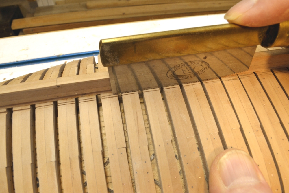
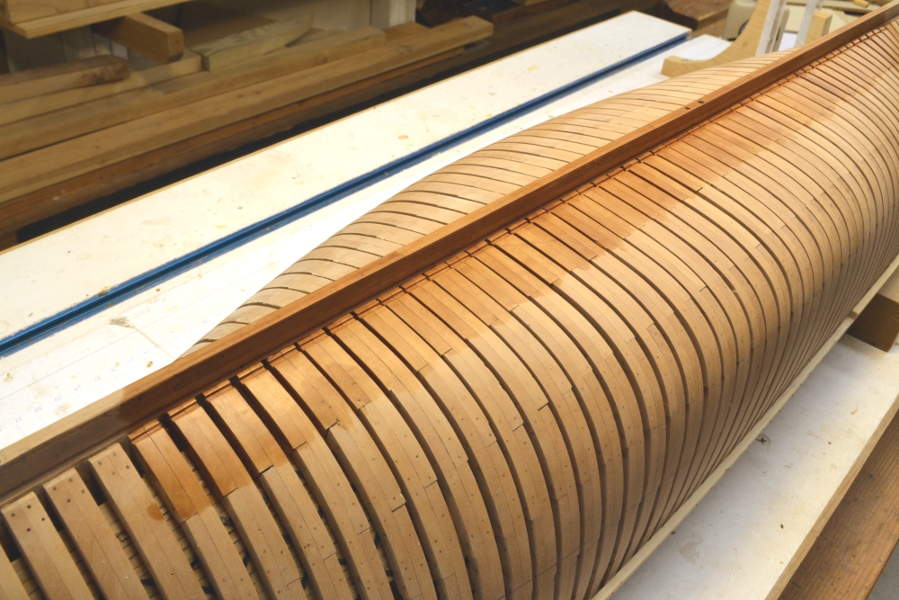
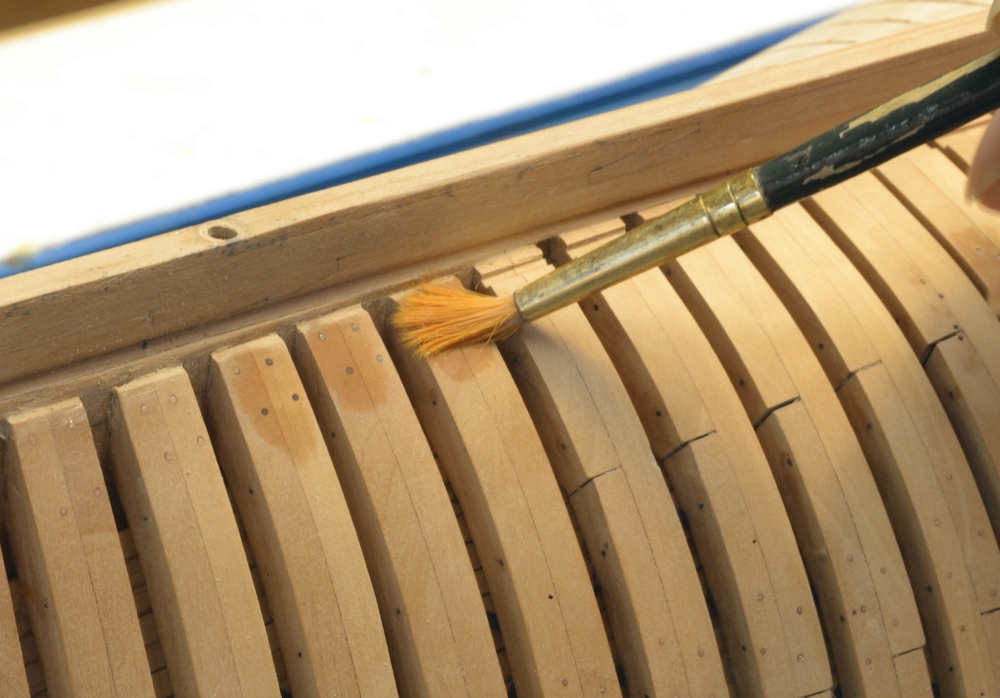
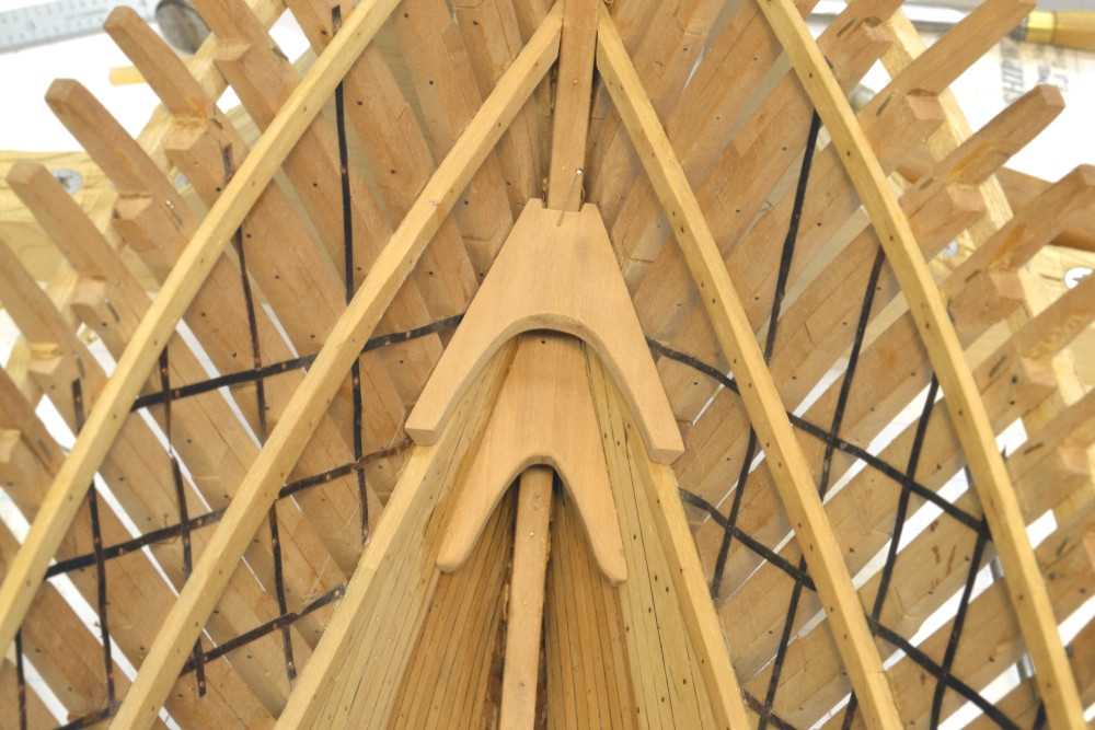
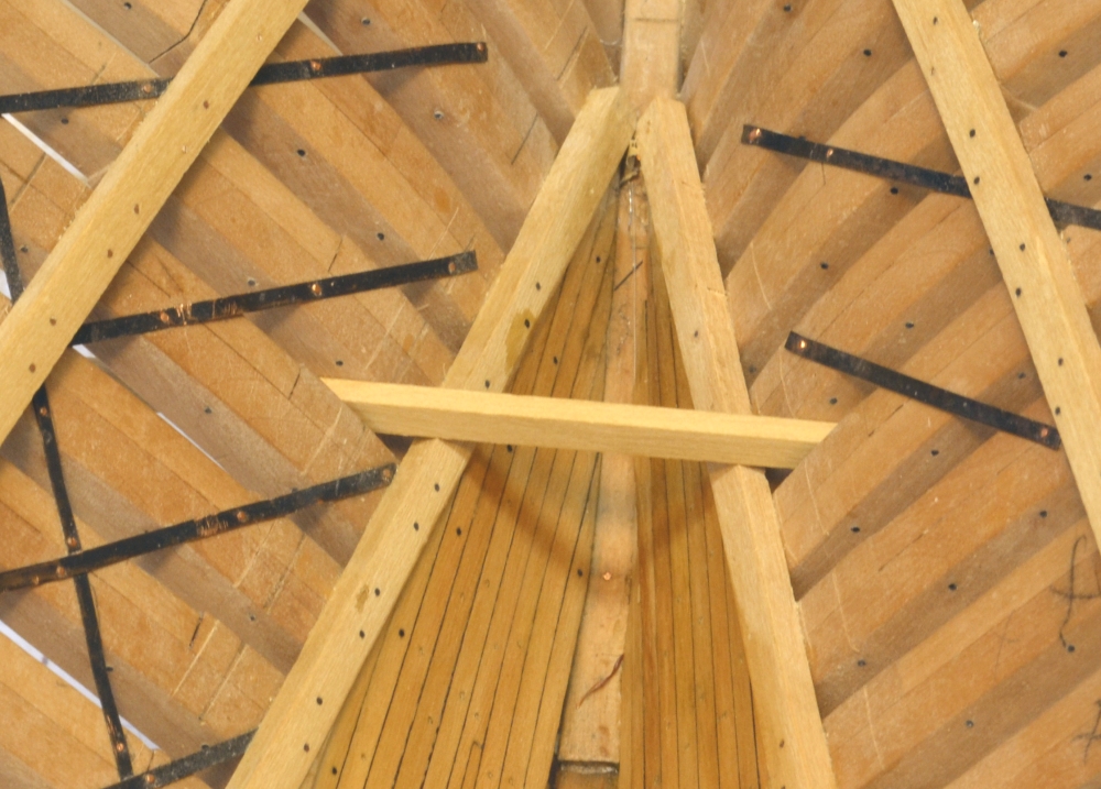
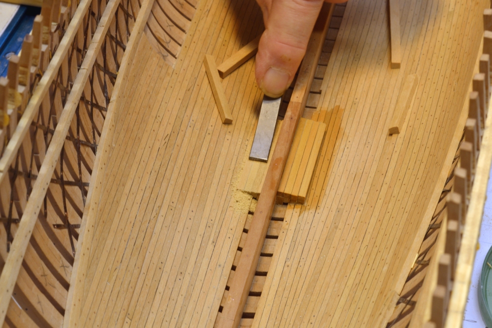
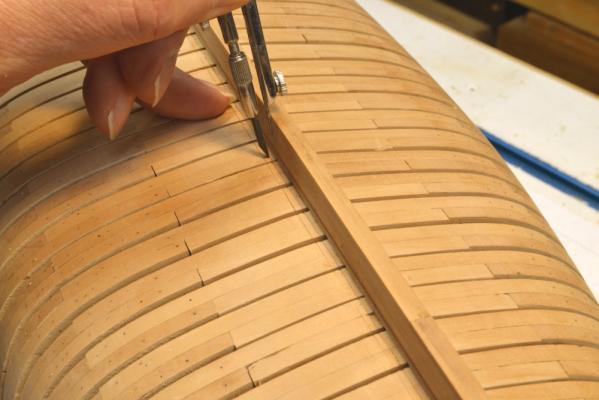
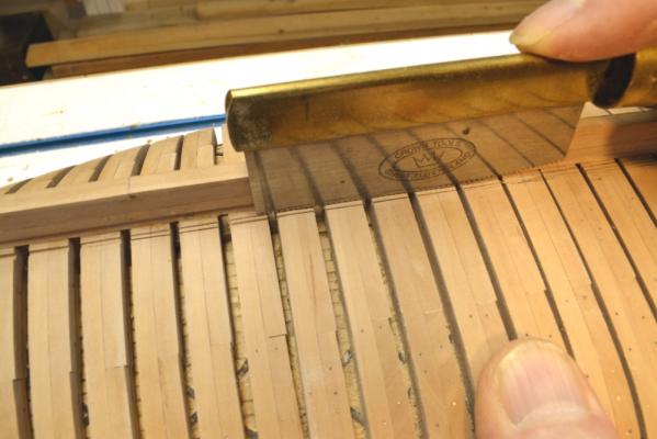
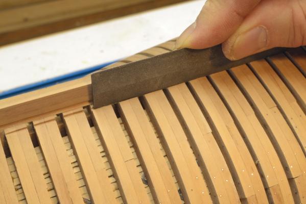
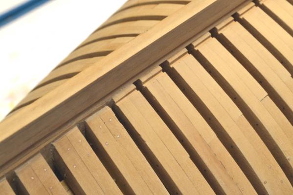
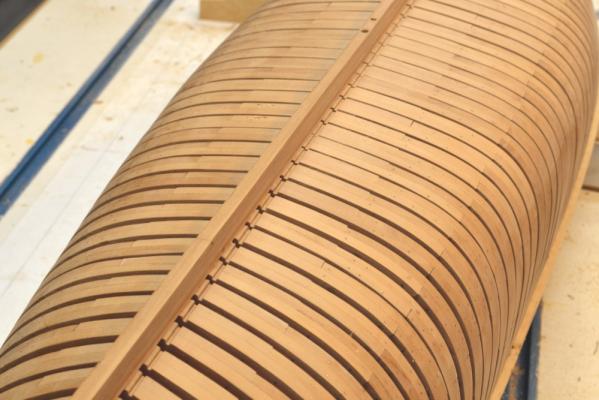
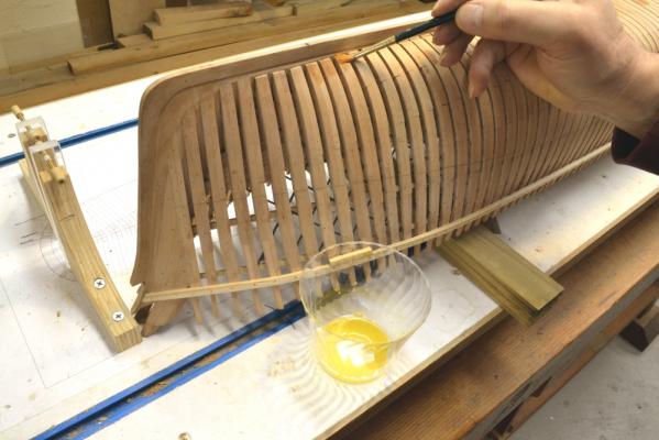
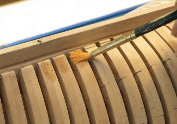
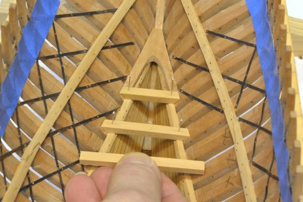
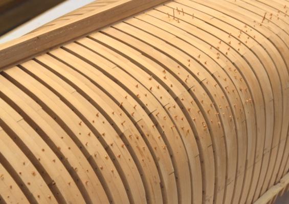
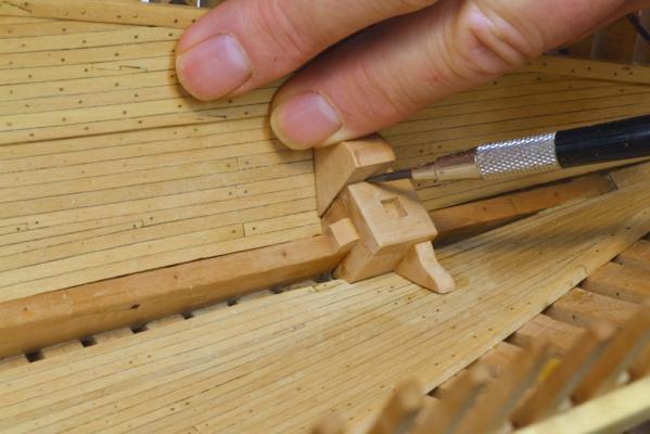
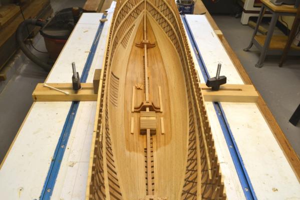
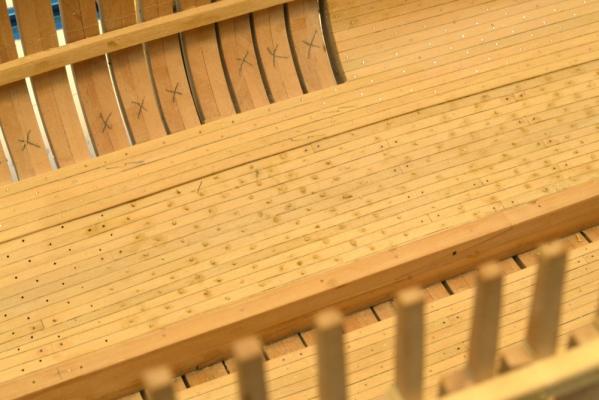
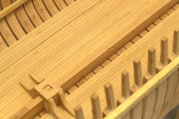
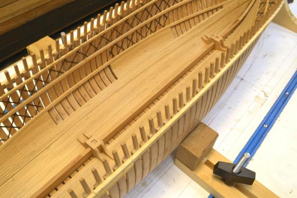
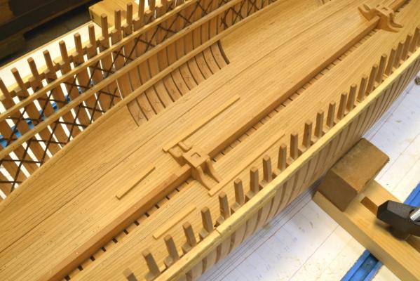
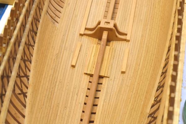
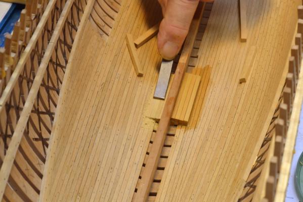
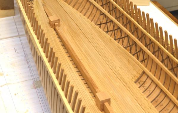
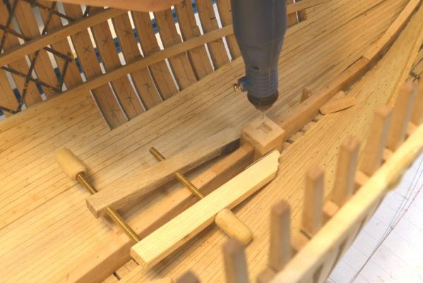
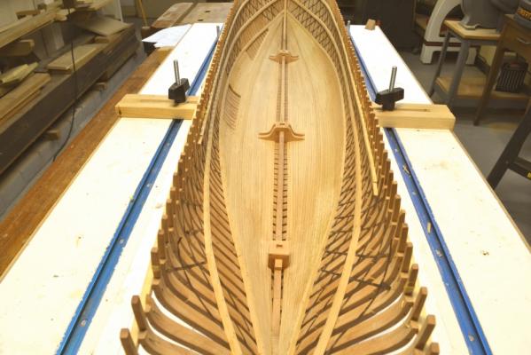
Young America - extreme clipper 1853 Part 58 – Limber channels Historical note: Young America, like most of her contemporaries, employed piston-type suction pumps to remove bilge water. The reciprocating pump pistons were driven by muscle power applied to large circular crank wheels on the main deck. Unlike the earlier chain-type pump that could only reach into a shallow sump cut into the floor timbers in the well, the suction pump could suck out water through a relatively small diameter pipe. This pipe could extend all the way down between the floor frames to the inner face of the outboard bottom planking – in this case the garboard strake - right next to the keel. The ability of the suction pipe to reach to the very bottom of the floor frames eliminated the need to pack the spaces between these frames – as was traditionally done to prevent stagnant water between frames and to inhibit rot in the lower timbers. Without this packing, air could circulate between the lower timbers. Lowering the suction point could also help keep the hold less wet. Provision still had to be made to permit water to flow to the pump suction. This was done by creating limber channels through the outboard faces of the floors. Each frame was notched to allow water to flow to midship. These channels were about 4” x 6” in cross section – located a few inches outside of the keel on both sides. These channels were often – perhaps normally – fitted with chains that could be used to break blockages. Debris could be cleared from above between frames by removing the limber boards next to the keelson. At the ends of the ship, triangular openings under the feet of the half-frames provided passages for water into the ends of the limber channels. I debated whether to include these limber channels on the model. They will be difficult to see. Cutting them also runs a risk of damaging the lower frames. To be consistent with the other levels of included detail, I decide to do it. In the first picture, the sides of the channels are being marked out using a compass with an extended lead, guided by the side of the point against the keel. I imagine that in practice these notches were sawed out before the frames were assembled. I elected to do it at this stage to help assure that the notches would run in straight lines. The next picture shows the sides of the channels being sawed out using a veneer saw. The veneer saw has straight (unset) teeth in a curved blade. This turned out to be an ideal tool for this. It is relatively easy to cut a straight line. A small (1/32”) chisel was then used to clear the material between saw cuts. Some different files were then used to clean up the channel. A straight, knife-edged file is being used in the next picture to shape the inside corners. The next picture shows the aft end of the channel on the port side. The channels end at the last full frames. In this picture the half-frames aft of the channel have squared off ends that form the triangular channel mentioned above. The next picture shows most of the channel on the port side. The channels were formed on both sides of the keel. I had intended to next finish the lower hull up to the lower futtock heads, but because more bolts will be needed later for the lower deck hanging knees I decided to finish only the full frames up to the floor heads at this stage. This area was given a final sanding and some polishing with Scotchbrite. The bolts in this area were then blackened with liver of sulfur as shown in the next pictures. I included this picture to give some idea of the LOS batch size and concentration. The next picture shows some bolt heads being blackened with a brush that is only damp with solution. Less is better. The bolt heads turn black almost instantly from the damp brush. In the last picture wax-turpentine solution has been applied up the floor heads on one side. Virtually all of this first coat was absorbed into the wood. There will be more coats later. Now back to installing bolts above the floor heads - and making deck beams. Ed

- 3,618 replies
-
- 22
-

-
- young america
- clipper
- (and 1 more)
-
Thank you, both. Ben, I try to use the correct fastening - iron, copper or wood. All these structural fastenings through the frames were iron, driven through then rivetted over on each end. Treenails on these ships were used primarily for non-structural common plank. Plank butt ends were usually driven iron blunts. If you page back a few posts you will see quite a few hundred treenails on the ceiling planking, whereas the structural bilge strakes above were iron through bolted - as were the fastenings for the iron strapping, deck clamps, hooks, etc. Most of these iron bolts were 1" diam driven through a 7/8" bored hole - then rivetted over on the ends. Some were larger - some smaller.
- 3,618 replies
-
- 2
-
-
- young america
- clipper
- (and 1 more)
-
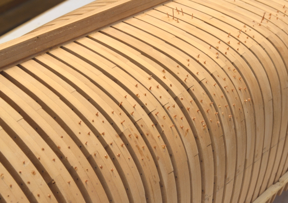
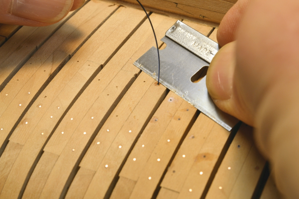
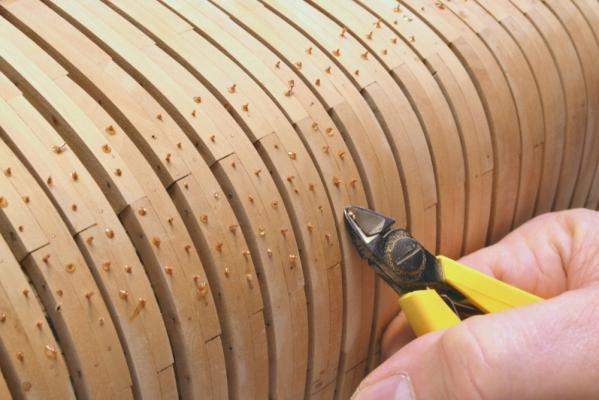
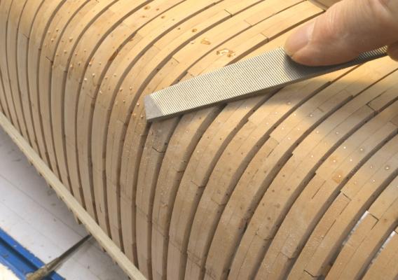
Young America - extreme clipper 1853 Part 57 – Lower deck hooks, outer hull work Its been awhile since the last post. Other demands have been interrupting the work. But some of the recent work – like drafting – is not something I usually report on. There is still quite a lot of that to do to keep ahead of construction. After dubbing off the lower deck clamps, all is ready for beam installation. I will report on beam fabrication later, but before beam setting could commence I wanted to get the fore and aft deck hooks installed. The first picture – taken at the bow - shows the hook below the lower deck hook installed and the lower deck hook itself being fitted. I lofted patterns for the deck hooks but the lower hook was hand fitted to the lowest strake of bilge ceiling. In the next picture the first two beams have been fit and pinned into place. The hooks were probably live oak and so are being modeled in pear. The deck beams were hard pine and are being made of Castelo – like the clamps and inboard planking. The next picture shows the aft lower deck hook in place and a few beams being fit. The blue tape in this picture is trying to protect the fragile ironwork lattice at the top where no deck clamps have been installed yet. The strapping at the bow is safely tucked under the main deck clamps. The outside of the lower hull was demanding attention, as can be seen in the next picture. The forest of protruding copper wire ends are the iron bolts securing the 8” x 8” bilge strakes on the inside. Each bolt is also accompanied by a drop of hardened epoxy. The first step in dealing with this is to cut off the ends as shown below. It is dificult to clip these off flush, but making them short helps in the next step – shown below. The wire stubs and hard epoxy are easily removed with a file, or in some areas with sandpaper. The file works best – i.e. fastest. When followed by sanding, virtually all traces of the epoxy are gone. Somewhere in this process all of the missing bolts had to be installed. Wherever these could not be drilled through from the inside, dummy bolts were installed from both sides. These were required near the ends where drilling holes square to the frames was not possible. When all of those bolts were added and cleaned up, dummy bolts for the iron lattice were installed on the outside. Monofilament was used for these. In the next picture one of these is being cut off flush. These were CA glued. They were placed along the lines of the strapping. There are, of course, quite a few of these bolts and the work is taking some time. The current plan is to get the hull finished and waxed below the lower futtock heads before returning to the work inside. After final sanding and just before applying wax finish to the hull frames, all of the copper bolts will be blackened. There is still some work to do before that. Ed


- 3,618 replies
-
- 27
-
-
- young america
- clipper
- (and 1 more)
-
Thanks for noting this, Ben. I do not think there is anything sinister going on here. Gerry Todd has been following the series from the beginning, I believe. These mini versions of the early drawings were posted as both jpg and pdf files in Parts 2 and 3 to show some of the views used in the Cad drafting. I later removed the pdfs at the request of the site mgt to discourage copying. These were undoudtedly downloaded before they were removed. These early versions are unfinished and contain many errors. It is also likely that I distorted them dimensionally to render them useless except for the purpose of illustrating the drafting approach, but I can't recall. I think we all have to accept that anything we post will be downloaded and could be used for purposes unintended - or just filed away for personal reference. Ed
-
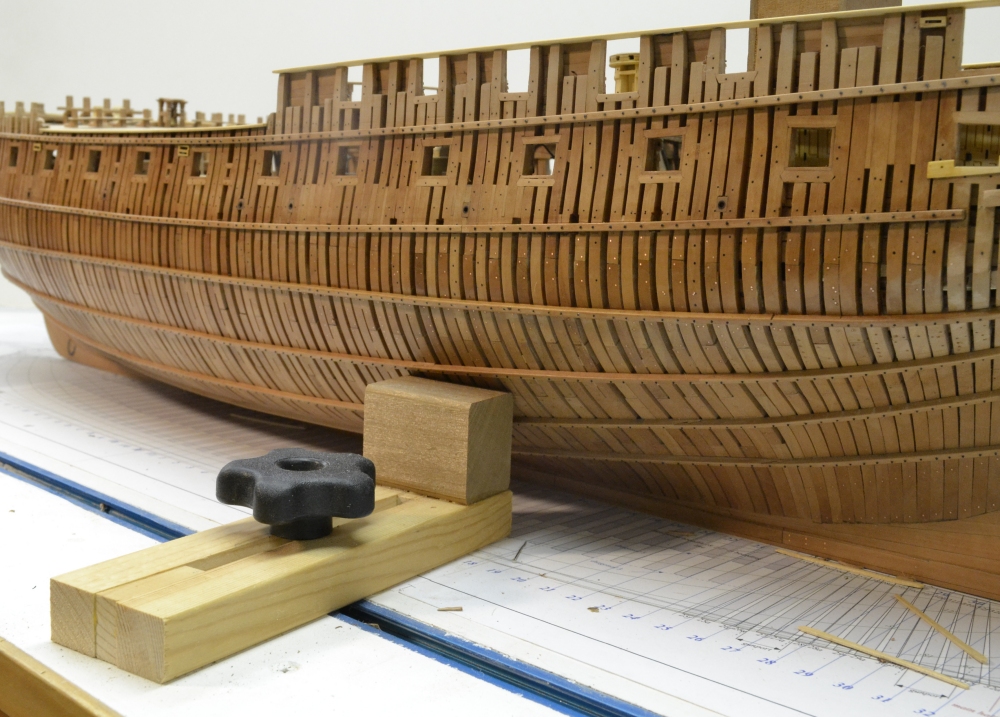
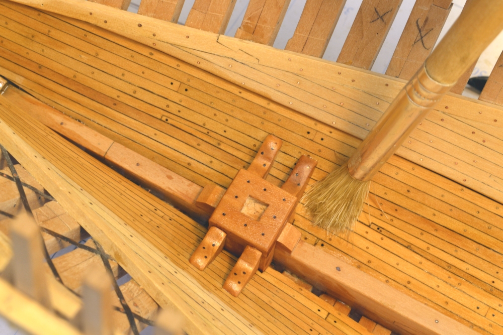
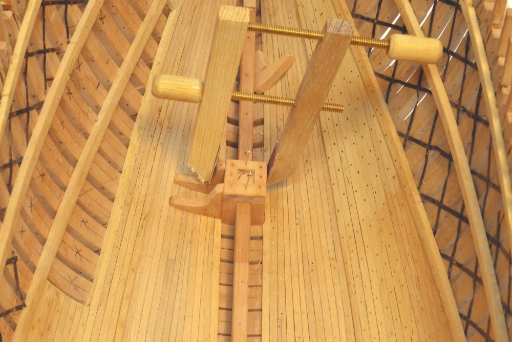
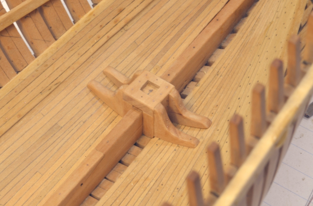
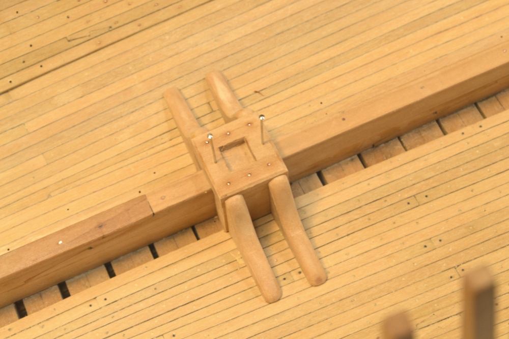
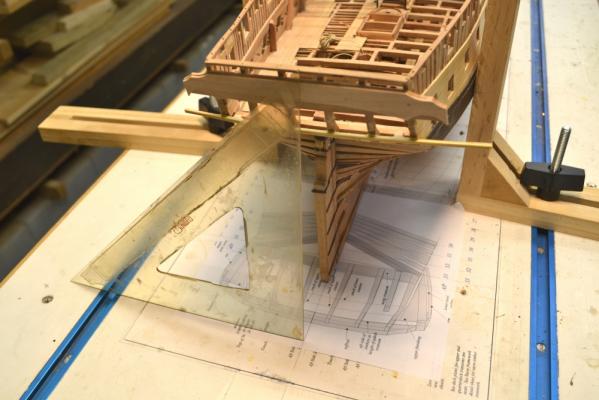
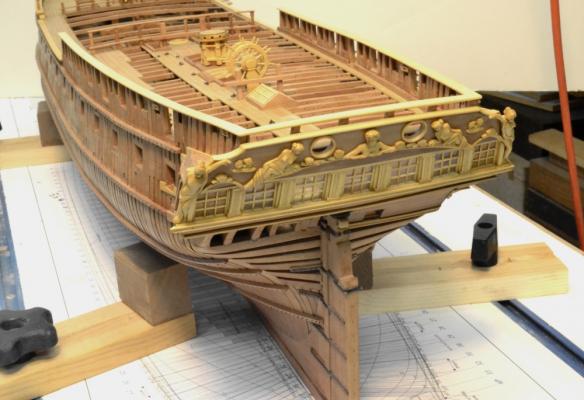
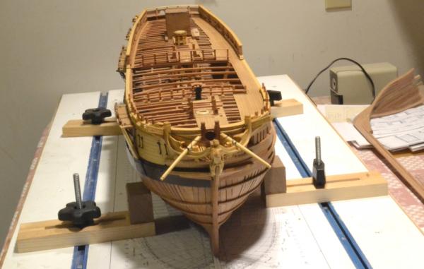
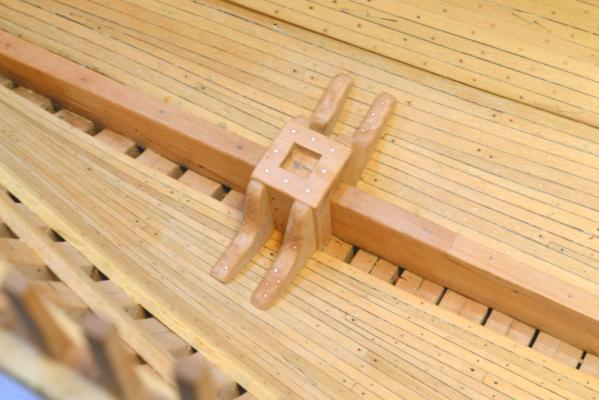
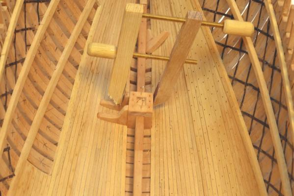
The Naiad Frigate Volume II – Addenda As with Volume I, I will post addenda as necessary to Volume II of The Naiad Frigate, here on this forum topic. Here is the first: Volume II, Addendum 1 First a printing omission: In the final book production process the last paragraph and part of the preceding paragraph of Chapter 28 was somehow left out. The last two paragraphs of Chapter 28. p 102 should read.: "You may wish to forgo the complexities described above in favor of simpler joints. The quality of your models will not suffer simplification in these minor details. However, I hope that the process described above will entice you to construct these authentically. When the lower deck hatchways are installed, the ladders to the orlop level platforms can be added. In keeping with our sequence and chapter arrangement, other lower decks details, partitions for example, will be covered with the upper deck framing in Chapter 31." Some additional information on supporting the model during construction – not included in Volume II. Once the rudder is installed the stern end support described in Volume I cannot be used. A different method was adopted for the remaining construction. The new supports made it easy to invert and replace the model in the upright position as required. Initially, the two “clamped squares” were used to support and hold alignment by butting them up to the sides with the model screwed down to the board – as shown in the following picture: With the clamps in position, a triangle is being used to center the top of the stern. Whenever the model is turned upright, repositioned or when the clamped squares are moved, this process should be repeated - fore and aft. It may be tempting not to do it if no precision construction is being done, but I recommend doing it every time to get in the habit. It is also possible that you may wish to take an unexpected measurement or dimension check. It takes only a moment to do this. In the picture it was being done before starting some work on the taffrail. Another type of support was constructed for this purpose as shown in the next picture: The clamping base was made from pine strips. Thesupport block was made of another soft wood, in this case white cedar, but any soft wood will suffice. The top inside corner of the block should be rounded. I made four of these. The next picture shows these supports being used. They are more versatile than the clamped squares. They fit nicely out of the way on the lower hull. Make sure the holddown bolts through the keel are tight and do not neglect the alignment check The last picture shows the four supports supporting the finished model. The above is also attached as a pdf that can be printed. Naiad Frigate Volume II Addendum 1.pdf

-
Actually, Mark, its apretty good question. In looking back through Volume II, Isee I neglected to show any pictures or describe how the model was supported upright after the rudder wasinstalled. I have dug some photos out of the archives showing this. I believe I will handle this an addenda on the V2 topic. I shouldhave it postedlater today. Thanks for he question and for your other comment. I'm very flattered. Ed
-
Thank you, Rob. I am sure Seawatch will get you the missing CD promptly. Good luck with the project. Ed
-
Thanks, everyone. Grant, thanks for posting that link. The best advice I could give to anyone on "where to buy" is, let your fingers do the walking in the search bar in your browser. I buy almost everything for the model online. As far as the formula for the wax solution is concerned, I don't really have one. Maybe use a tablespoon or two of wax to quarter to a half-pint of turps. The wax can be left to dissolve or helped along with some heat. Boil some water in a pot, remove from the heat and set the jar in with a loose or removed lid. Do not heat it directly or do this near an open flame. I make a pretty thin solution to help it penetrate. If solid wax appears on the surface when you apply, add solvent to the mix - so everything penetrates. I have been using the same half-pint jar that I started Naiad with. It doesn't take much wax and the thin mix makes it easier to apply. The turpentine all evaporates, leaving just he wax. More can be appied to get he desired finish. Excess wax or gloss can be removed with a turps on some paper towel or a cotton swab. Once it penetrates forget gluing on it. Ed
- 3,618 replies
-
- 6
-
-
- young america
- clipper
- (and 1 more)
-
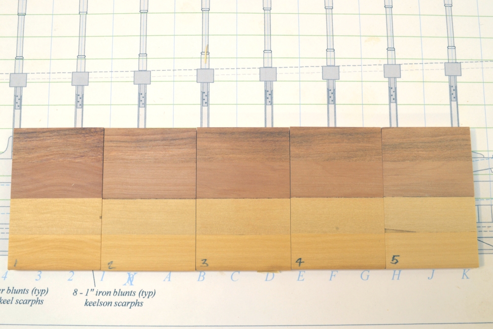
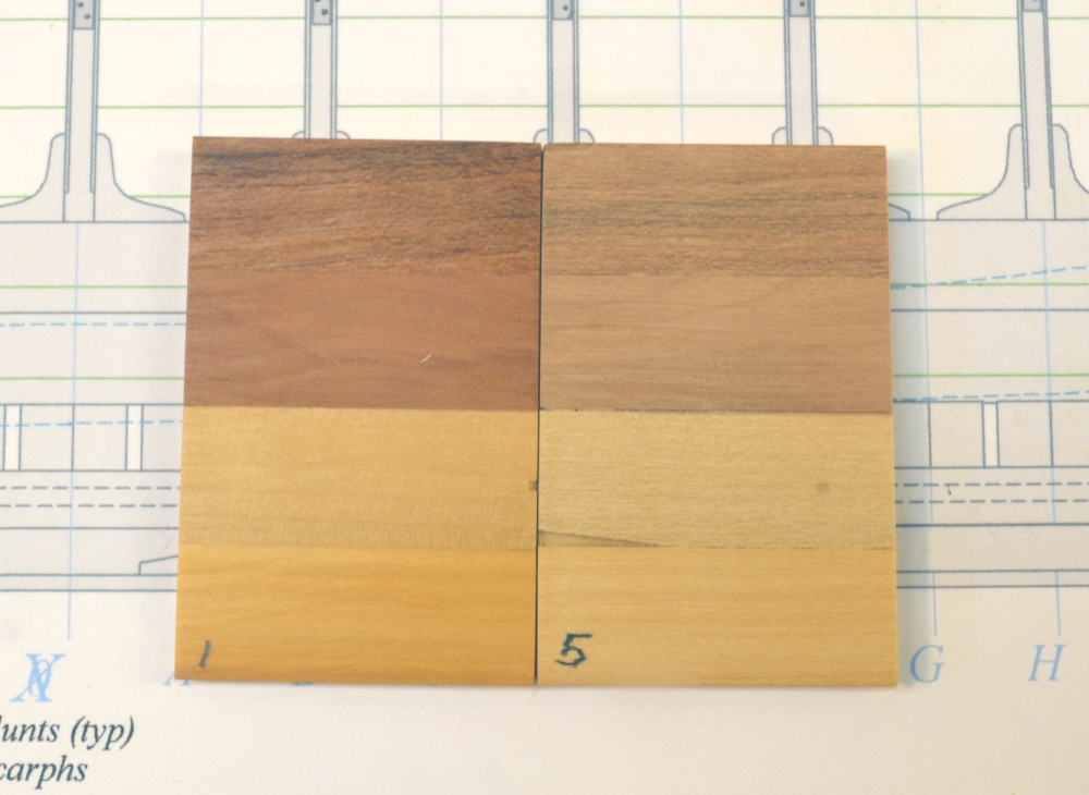
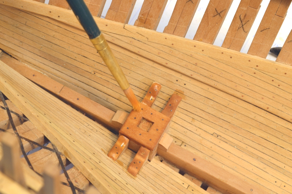
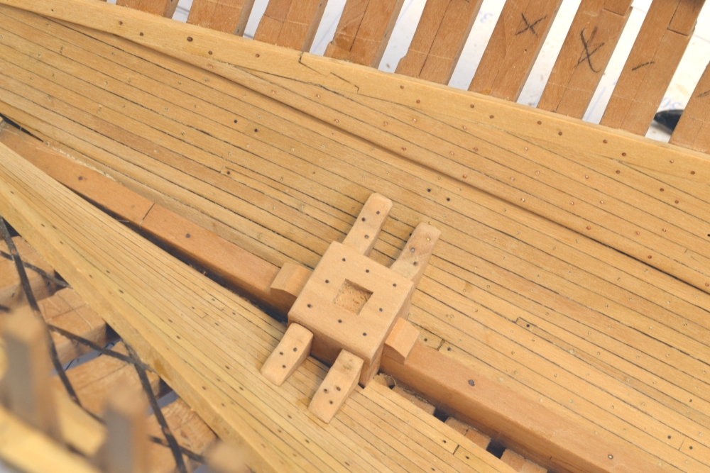
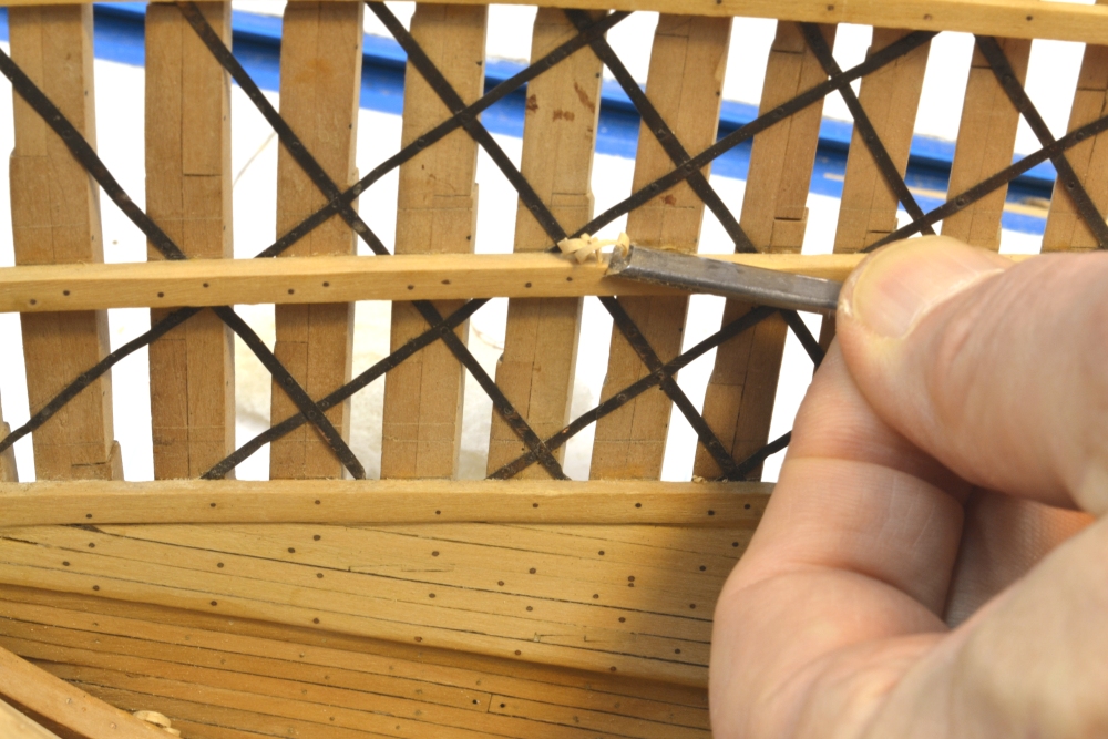
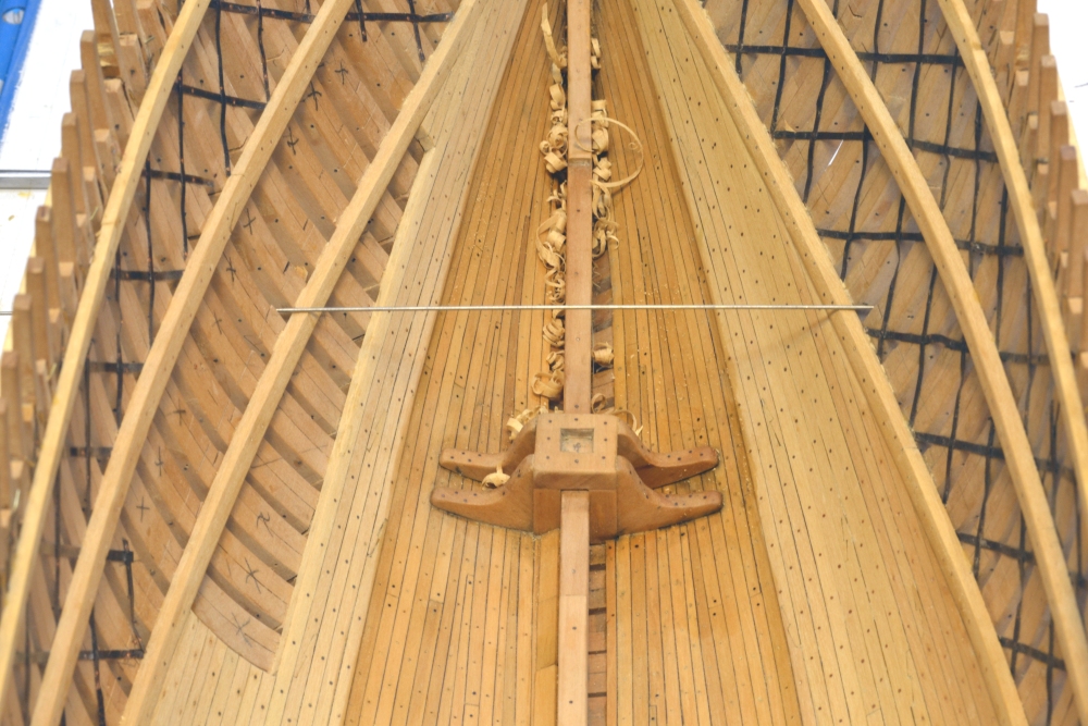
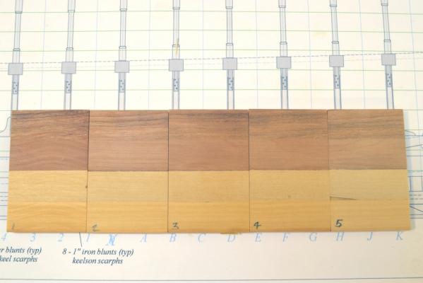
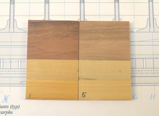
Young America - extreme clipper 1853 Part 56 – Wax finishes, deck clamps Thanks, Jim and amateur for your comments. Before getting into the next part of the work, I have included some information on wax finishes, since that got some discussion after the last post. Also, I need to make some decisions on finishes soon. The first picture shows some wood samples that have been treated with various wax finishes. A composite sample was prepared with four strips about ½” wide, glued to a plywood base, sanded and then buffed with steel wool. The top strip is heartwood cherry, below that is Swiss pear, then Castelo (sometimes sold as boxwood) and at the bottom is genuine European Boxwood. The primary woods on this model will be Swiss pear (for oak) and Castelo ( for hard pine). The samples were cut apart and all treated with turpentine/wax solutions, 2 coats, and then allowed to dry for 24 hours. They were treated, from left to right as follows. 1. natural, ordinary beeswax, 2. a blend of white and yellow food grade beeswax. (This yellow is less yellow than the natural wax – probably less pollen.), 3. white food grade beeswax, 4. petroleum based microcrystalline wax (Renaissance), also in turpentine. Sample 5 has no finish. Sample 5 is the lightest. Samples 2,3 and 4 are virtually identical and very slightly darker. Sample1 is the darkest. The next picture shows sample 1 next to the unfinished sample 5. The contrast here is more evident. After looking at all of these in different lights it is clear that the natural beeswax is darkest and most yellow. The less pale yellow shows up as lighter than the blend - which makes no sense. That, the white beeswax and the microcrystalline are virtually the same shade as the unfinished. The slightly darker look may be unevaporated turpentine. Turpentine dries slowly. We’ll see what happens in a few days. All the wood samples were chosen from pieces with pronounced grain, relatively speaking. The test shows the quite heavy grain in the cherry as opposed to the other woods. I will probably do some more work with the pale yellow wax to tone down the natural. We’ll see. For me, genuine boxwood probably does not need any yellow wax. Castello needs some yellow to bring it to life. Pear has a dusty white hue that also benefits from some darkening and some yellow – all my opinions, of course. Although I did not test oils, varnish, shellac or polyeurthane, all are much darker and more yellow. Water based sanding sealer (straight acrylic emulsion) has no color. The next few pictures show finishing work on the mizzen step. In the first picture very dilute liver of sulfur solution is being applied to the copper bolt heads to turn them black. I have been advocating liver of sulfur to blacken copper for some time – including in the Naiad books – partly because it leaves surrounding wood unaffected. I want to stress here when used like this the solution needs to be dilute (Do tests.). In the next picture the solution has been left to dry on the wood. At this point the solution has self-neutralized to white and dried. Two of the bolts had some residual epoxy on them and did not turn black, so they had to be sanded again and retreated after this picture was taken. Note that there is no trace of stain from the LOS. If too strong a solution is used, the wood may show gray-green blotches. If this happens, that can be removed with white vinegar. I have only had this happen once – but vinegar seems to be the antidote. The next picture shows the step being treated with wax solution. This picture was taken a few minutes after the area was wetted with wax/turp solution. In the picture it is being dry-brushed to remove and spread excess. The last few pictures show work on the lower deck clamps. The top surfaces of these need to be “dubbed off” horizontal. As installed, the clamps are angled to varying degree over their length. The first picture shows the pronounced angle near the bow. The wood strip in this picture should lie flat on the clamps and be horizontal. To achieve this, the clamps were pared over their length with a chisel as shown below, then faired out with a file. Because the angle varies the paring needs to be tested while proceeding. In the next picture a straight steel wire is being used for a check. The wire fits more easily between the frames and the iron latticework. After dubbing off the clamps, the next step will be installing the reinforcing breast and deck hooks at the bow and stern. Ed


- 3,618 replies
-
- 28
-
-
- young america
- clipper
- (and 1 more)
-
Thank you, David. It is getting quite strong - stronger than a model needs to be with all those epoxied bolts through the frames on the bilge strakes. There's still a lot of heavy reinforcing ahead - for example 15" x 15" waterways at each deck. Ed
-
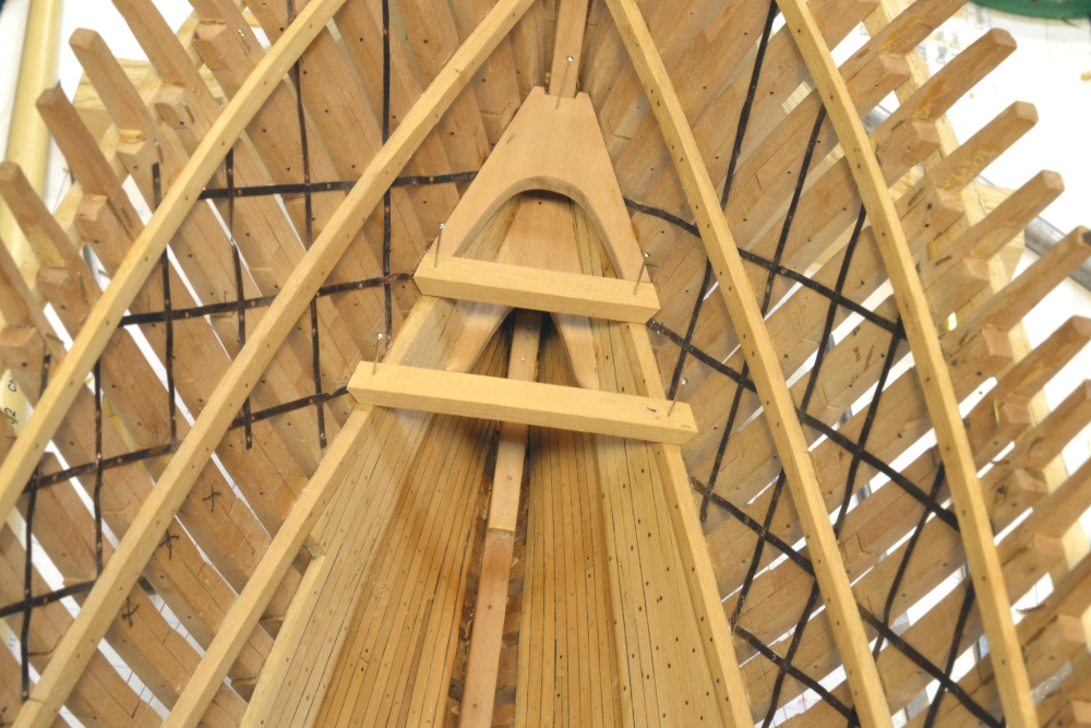
Thank you both and thanks for the "likes". Druxey, I will be installing only a few limber boards as shown. There were no fillers between frames on these ships. The primary limber channels are on the underside of the floor timbers, several inches outboard of the keel, so the drainage channel is actually below the frames right on the garboard strake. Having this below the frames alleviated the need for fillings and permitted air gaps all the way to the keel - although starting at some distance above the keel these gaps were filled with salt.. The underside limber channel was about 5-6" square, cut into each frame. It was often - perhaps normally - fitted with a chain that could be worked to dislodge debris. This debris could presumably be removed from between the frames by removing the limber boards. All this was made possible by the use of suction pumps instead of the earlier chain pumps. The suction pipe on these pumps could fit between frames right down to the outer planks. I will probably be cutting this channel on the bottom before too long. You may recall that his channel started as a triangular space under the squared off feet of the half-frames. Ed
- 3,618 replies
-
- 1
-
-
- young america
- clipper
- (and 1 more)
-
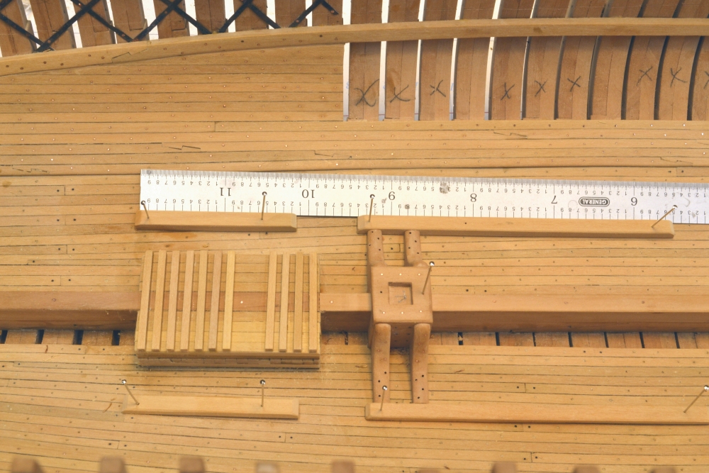
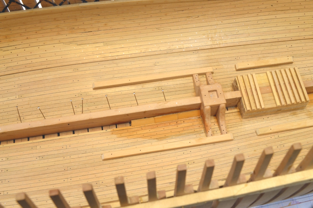
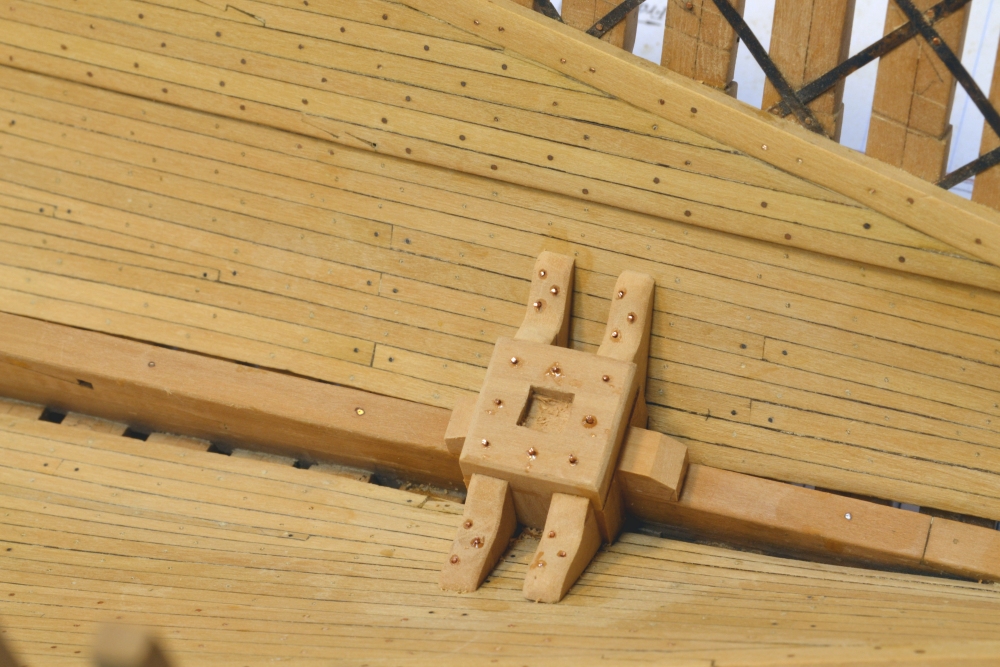
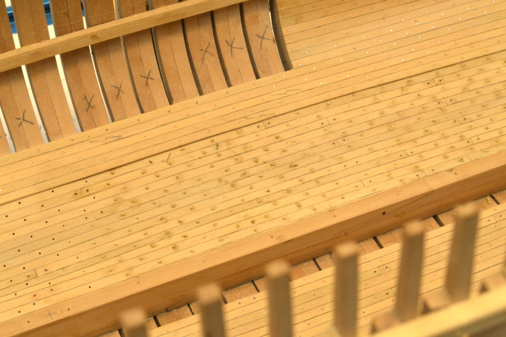
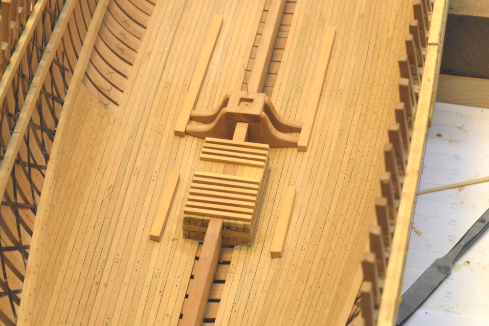
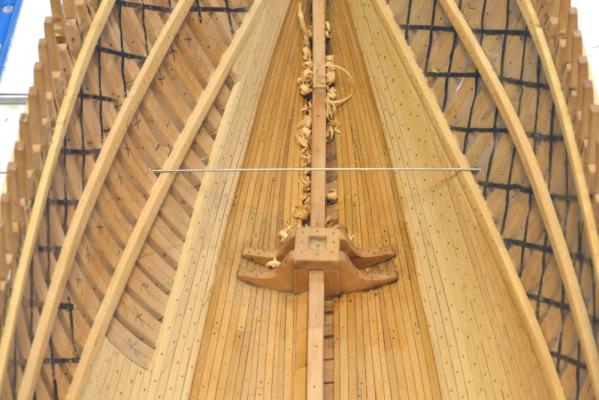
Young America - extreme clipper 1853 Part 55 – More hold work The plan has been to finish all of the work in the lower part of the hold so finish can be applied to this area before moving upward to work on the lower deck. The first picture shows the main mast step and the water tank base. The members to support the off-center beam pillars are being positioned in this picture using a straightedge. In the next picture they have been glued down. This picture also shows the addition of one last 6” wide strake of planking to bring the width of the limber channel down to the required 10”. In this picture a few limber boards have just been glued over that final channel – hence the wet spot. The pins on the opposite side are holding the last plank on that side. The next picture shows some more limber boards in place plus a pile to one side. The ceiling planking and other structures have just received one coat of beeswax-turpentine finish. When dry, the shade of this finish will be about halfway between the two shades in this picture. Surfaces that will receive glue later have not been coated. The next picture shows some work on the Mizzen step. The chunk of pear being marked will be cut to the shape of the knee and then slit into two to fashion the forward knees. The aft knees are roughly fit at this stage. In the next picture the mizzen step is almost finished. Bolts have been installed down through the frames with epoxy. These will have to be filed off and the assembly finish sanded. The bolts will then be blackened to represent iron. The last picture shows the current status. With the ceiling planking darkened the contrast with the bilge strakes above is clearer. This shows the convergence of the heavy bilge strakes forward to butt into the bottom of the lower deck clamp. In this configuration the heavy band acts like a girder to reduce hogging strains. It will soon be time to start work on the lower deck framing. Ed


- 3,618 replies
-
- 41
-
-
- young america
- clipper
- (and 1 more)
-
Exceptional work as always, Mark. Flawless. I sometimes forget the 1/64 scale. At this smaller scale, perfect fit up is harder. Well done. The stern is certainly complex. Wait till you get to the head rails and timbers. I sometimes find it helpful to think of how the original was erected - one piece at a time, rather than with prefitted sub-assemblies. Sometimes it is easier having a solidly anchored piece to fit to or measure from, but you seem to be doing just fine so I will just continue to watch. Ed
-
Thanks for the invitation, David, but it might be easier to bring Manitowoc to YA. I don't fancy this in checked baggage - or in a U-haul. Nice thought, though. Thanks. Thanks, Robin. Ed
-
Thanks yet again,everyone. Your comments are always most welcome and appreciated. Sherry, the workshop has actually become "the shipyard" in everyday speak around here. Your comment is apt. One of the things I like about building the ship upright from the bottom up is that I get to ask myself questions like, "How did they drill those long holes in that confined space?" Of course all this effect is lost when I have to invert the model to file off boltheads on the bottom. Andy, thanks for he input on the tank issue. I had assumed, as did my source (Mr. Crothers in this case) that these tanks would have been baffled internally regardless of the design. However, maybe not, and perhaps that is the reason for the tall columns vs short broad hold tanks. I'm not sure where the hull center of gravity is. Perhaps not much of the water is above it. I'll tke a pass on your offer of more information and move on to he next problem. Had enough fluid mechanics for one lifetime. David, thanks for the suggestion but I will pass on that too. I don't want to further expose how little I know about the subject. Ed
- 3,618 replies
-
- 3
-
-
- young america
- clipper
- (and 1 more)
-
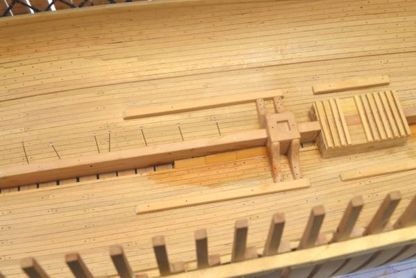
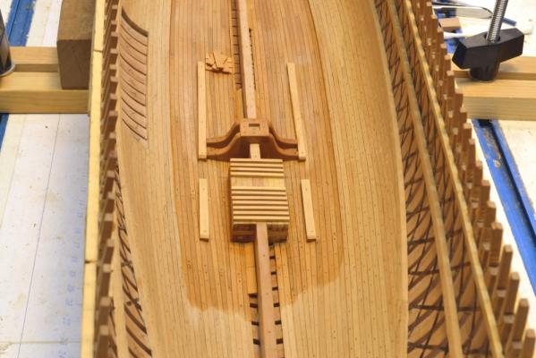
Young America - extreme clipper 1853 Part 54 – Treenailing, steps, water tank plinth The first picture shows the treenailing of the ceiling planking on the port side in progress. Treenails have been glued in and clipped off on the center to right side of the picture. To the left, holes have been drilled and are waiting for nails. The next picture was taken later around the midship area. In this picture the nails have been filed off flush and the planking finish sanded and polished up with some steel wool. The iron blunts at the butts are more pronounced. The step of the main mast is in position but has not been permanently fixed. It still needs assembly bolts. The next picture shows more of the port side ceiling and both forward mast steps. I had to catch up on some drafting in order to move forward with the permanent fixing of the steps. I had not yet detailed some additional hold members. The next picture shows some of the additional members required in the midship area. Some of the pillars in this area are located outside of the openings for the main hatch, the mast partners and the two large square tanks that stored fresh water. These off-center pillars will be installed on the long base members shown loose in the above photo. The next picture shows the beginning of construction of the plinth that will support the water tanks. These two iron tanks rested on the keelson and are about 6 feet wide, so additional supports were needed on either side. These are being built up as a solid base of 8” x 8” members. The first layer of these is shown in the above picture. The next picture shows this first layer being leveled off on the port side. The lower members were shaped to match the hull curvature, but the final structure needs to be flat at the top. The next picture shows the completed plinth. The top of this substantial base has been fitted with 6” x 6” dunnage beams. The two flat-bottomed iron tanks will rest on these. The aft tank is 6000 gallons and extends up to just below the main deck, a height of about 20 feet. The smaller 2000 gallon tank is 12 feet high with its top just under the middle deck. I don’t know why these were so tall. I would have thought shorter tanks with a larger footprint in the hold would be better for stability, but the source is reliable. These were usually round, but Webb installed square tanks in Challenge and that was the basis for this design. I assumed no change would be made in the short interval between Challenge and YA. The pillar support members seen in this picture have not yet been shaped or installed. There will be three pairs of pillars on the forward set and two pairs on the set astride the tanks. The last picture shows the final installation of the foremast step. After gluing the assembly on to the keelson and the ceiling planking, holes for the bolts in the horizontal arms of the knees were drilled down through the frames. Copper wire through-bolts were then epoxied into place. Long bolts through the centerline of the cap were inserted into the keelson in what had been locating-pin holes. All these bolts were iron and will be blackened before applying finish. Ed

- 3,618 replies
-
- 25
-
-
- young america
- clipper
- (and 1 more)
-
Thanks for the comments and the useful input on waxes and solvents. I do not know if the relative differences in these materials is significant to our purposes or not. However, to be prudent I would use microcrystalline (conservator's, Renaissance) wax on metal and rigging where color makes no difference. I would thin it with some high quality naptha-type solvent - see below. Some future generation may thank us for this caution. I see no reason why either material should not be used on wood and would let the desired appearance be the guide in this case. I expect to test these waxes - mainly to see what beeswax blends look like - on wood samples and will post some pictures later. As far as solvents are concerned,I expect to continue to use turpentine to thin beeswax - perhaps from habit, perhaps because I prefer the aroma in the shop, or maybe I like the fanciful idea of an "all natural" finish. (Turpentine comes from trees.) All of these solvents work pretty much the same way. Mineral spirits is essentialy naptha - a broad cut of distillates from petroleum refining. Odorless forms have had the aromatics (benzene, toluene, xylene, etc.) removed. Since these are the less healthful constituents, odorless is probably safer to use - and your shop will smell less like a refinery. I have often wondered if the product sold as "naptha" is much different from mineral spirits. There are light and heavy cuts of naptha so perhaps it is one of these variants. Lighter cuts would be more useful for cleaning. Ordinary "mineral spirits" may be the heavier - more oily - cheaper cuts - good to thin paints/varnishes and clean brushes. I don't really know the specific differences. Anything sold in small containers for artists is probably higher quality and always more expensive. So, thanks again for the input. Ed
- 3,618 replies
-
- 2
-
-
- young america
- clipper
- (and 1 more)
-
Thanks, Gaeton. A little science always helps. As the table indicates beeswax is pretty close to neutral - close enough for me to stop worrying about it on blackened metal. Also, thanks for the testimony for beeswax as along term furniture finish. This agrees with what I have observed as well. Ed
-
David, I believe that the main drivers were cost and construction time - with perhaps an emphasis on the latter. The demand for these ships was very high and the shippers wanted them fast to capture the markets. Forest resources in the US were basically unlimited in the mid-19th century - or thought to be so at the time - and very good ship timber was plentiful - unlike in England where the Navy had essentially deforested the island. Ed
-
Piet, thanks for the tip on the odorless mineral spirits and for your interest in the build. Mark, a very good and interesting question. A variety of inboard reinforcements were used by different builders - to stiffen the hull and reduce hogging strains. I have based the design for the Young America model on what is known about Webb's practices on his ships. Bill Crothers book discusses many of the methods used and was a primary reference for me - among some others. I have mentioned earlier that Wm Webb seemed to be more economical in the use of timber than some other builders, so heavy supplemental sister keelsons, keelsons at the bilge level, long diagonal riders on the ceiling, hogging chocks, etc. - common features - were probably not used in his ships. What you see on the model is essentially it. The package includes: increased frame spacing and smaller frame timbers toward the ends to reduce weight, 16" x 48" deep straight keelson stem to stern, diagonal iron strapping, heavy "bilge ceiling" around the turn of the bilge up to the lower deck clamp. This last item is deceptively strong reinforcement. It consists of 8" x 8" timbers iron bolted through every frame with strakes probably edge bolted together. It parallels the line of the lower futtock heads, so it converges into the lower deck clamp toward the fore and aft ends of the ship where tapered timber ends are edge bolted into the clamp - forming a sort of girder with the clamps and the clamp-parallel inboard members above. Also, the deck beams, located uniformly at every other frame (no guns to consider) were heavily kneed and bolted through the clamps and the frames. This is the best assessment I could make for the model - considering that no specific detailed design or specification for the original exists. From what I gather, these later American builders often eliminated some traditional wood pieces in favor of more bolts. They used a lot of bolts. You can't argue with success. I wonder how many of those 18C RN ships could go around cape horn fifty times, as YA did. Webb was doing something right. Hope this answers your question. Ed
- 3,618 replies
-
- 1
-
-
- young america
- clipper
- (and 1 more)
-
Thanks for mentioning that, druxey. I do use conservator's wax (Renaissance Wax) and should have mentioned it. It is a petroleum product and as you say is water-white and pH neutral. I believe it is also more stable and lasts longer. I often use it on metal. It adds no color to the wood and may provide more permanent protection than beeswax. Beeswax does seem to last for decades however. I use beeswax on wood as a personal preference because it deepens and warms the color of the wood somewhat. It also penetrates when used in solution with turpentine - giving depth in appearance and additional protection. I have not tried diluting conservator's wax, but I suspect it would be best to do that with a petroleum based solvent like mineral spirits. I don't like the smell of that on the wood - although I have used ms with tung and other oils on furniture work. The acidity in beeswax could be a problem I suppose, perhaps on metal like blackened brass or copper, but I have not seen evidence of it on some very old work. I think acidity is a non-issue on wood. I think the yellow color - and perhaps the acidity - in beeswax is from pollen. White beeswax is processed to remove most of that. I would probably not try to blend the two different types. So, like most finishes - a heavy dose of personal preference in the decision. Ed
- 3,618 replies
-
- 1
-
-
- young america
- clipper
- (and 1 more)
-
Mauricio, thank you. I have not tried white beeswax, but I intend to. The natural yellow wax imparts an nice warm color to the wood, but sometimes it is a bit too yellow and turns the pear an orange hue that I do not like. I may try some blends. Good question. Ed
-
Thank you all for these very generous comments. Ed
-
David, The simple answer is yes, I do apply finish progressively before areas become innaccessible. I do not use stain or varnish. On Naiad, except for the black wale, all of the wood was left in a natural color and the only finish used was beeswax dissolved in turpentine. This was applied to areas after all gluing a metal blackening was completed on that area. With the dissolved wax finish, adding new finish dissolves any old finish so there is no problem with overlaps, as for example there is with oil finishes where the gloss increases with each coat. Excess wax o gloss can also be easily removed or cleaned with turpentine or new soluton - unlike polymerized oil. There is also no problem with oil in crevices oozing out and polymerizing later. Also, I like the look. On Young America I have not decided on finishes yet. I will vry likely paint some of this model. It is also likely that I will use the wax finish on the natural wood. The first wood to be finished will be the hold ceiling planking/keelson up to the lowest bilge ceiling strake - after the steps, fastenings and limber boards are installed. Next will be the lower hull exterior which will have exposed frames. this will be done after fitting the rudder ironwork. Using wax, it is possible to finish through one deck framing. I may install hanging knees before beams on this model, allowing lower areas to be finished before beams interfere - not decided. Ed
- 3,618 replies
-
- 3
-
-
- young america
- clipper
- (and 1 more)
-
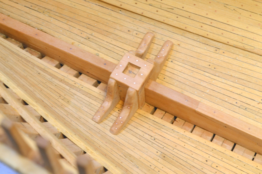
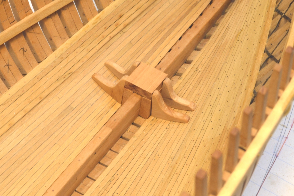
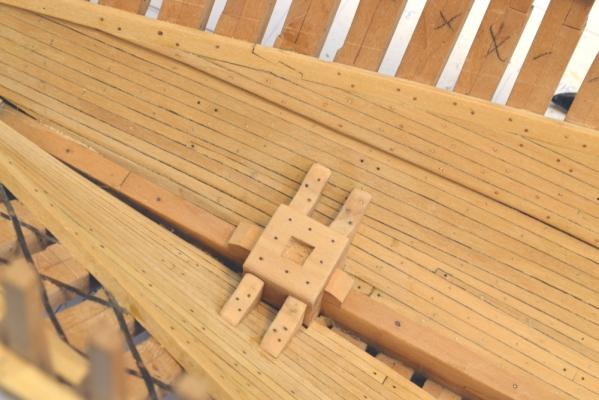
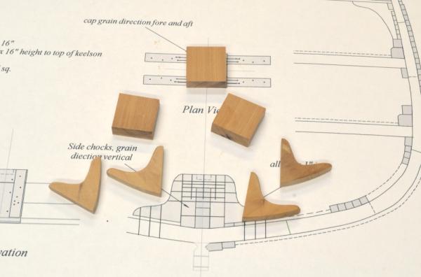
Young America - extreme clipper 1853 Part 53 – Mast Steps With the ceiling planking finally installed, I could move on to some other, more interesting, work – the mast steps. The planking and some of the bilge ceiling still needs to have many fastenings installed before the mast steps are permanently fitted, but for a change of pace I decided to make the steps next – installing fastenings concurrently in small doses. The first picture shows the parts of the foremast step before final fitting. The next picture shows the general configuration of these roughed out, unfinished parts. The typical step consists of a cap – as yet unmortised – two side chocks with their grain direction vertical and four knees. The next picture shows some of the parts of the main and mizzen steps. I installed a horizontal chock under the cap of the mizzen step to provide additional height for the knees. The caps are supported directly on the keelson and the side chocks. These chocks rest directly on the frames. I mentioned earlier that the limber channels by which water runs to the pumps are cut on the underside of the frames on these ships, so the step chocks as shown would not block this flow. In the next picture a clamp has been used to hold the chocks against the keelson. Tthe cap was then glued only to the chocks, so the assembly could be removed. In this picture the cap glue has set and holes for bolts into the chocks are being drilled. The cap will next be bolted to the chocks (copper wire epoxied) to secure the connection. Pin holes to precisely locate the step are also drilled into the keelson and will later be used for bolts. Below, the foremast step has been pinned in place for fitting and gluing of the knees to the sides. One of the knees is being glued in this picture. The step is still removable. It can be installed permanently only after the treenailing and bolting of the ceiling planking is finished. The next picture shows the knees attached. In this picture the step assembly had been removed to the bench for the installation of the bolts holding the knees to the side and the simulated bolts through the chocks and the keelson. The next picture shows the main mast step with the knees glued but not yet bolted to the sides. The last picture shows the positions of the steps within the hull. Knees are still needed on the mizzen step. This picture also provides a good view of the extent and shape of the ceiling planking. At this stage all of the ceiling bolts on both sides are installed, but the Treenailing of the port side has yet to be done. Ed


- 3,618 replies
-
- 25
-
-
- young america
- clipper
- (and 1 more)