HOLIDAY DONATION DRIVE - SUPPORT MSW - DO YOUR PART TO KEEP THIS GREAT FORUM GOING! (Only 13 donations so far - C'mon guys!)
×


EdT
-
Posts
2,213 -
Joined
-
Last visited
Content Type
Profiles
Forums
Gallery
Events
Everything posted by EdT
-
E&T, When you find a way to get consistent results, I know many will welcome your sharing that with us. What you have done so far looks pretty good to me. Druxey, I probably need to look harder. My attempts to find DI water or even distilled water at the supermarket have not been successful - but they have been more casual than determined. Thanks for the info. Ed
-
By the way, the blue stuff is no health potion either. Here's a link to the Birchwood msds for their product - essentially the same as Blacken-It, Hobby Black, etc. but with a wax to make it a gel. Selenious acid type. I couldn't find an msds more specific than this. But this should do. https://www.birchwoodtechnologies.com/downloads/msds/7503_ANTIQUE_BLACK_GEL.pdf Ed
- 346 replies
-
- 1
-

-
- terror
- polar exploration
- (and 2 more)
-
E&T, Druxey seems to have mastered the blue solution, so I would follow his advice. Druxey, do you buy lab grade DI water or are you running tap or distilled water through an ion exchange resin (Brita for example)? I don't think there is any HCL in Blacken-it, but there is in Win-ox - HCL (muriatic acid aka hydrochloric acid) and tellurium dioxide - both are a bit nasty and require care and ventilation in use. As I say, I have not tried it yet, but here is a link for it: https://shop.rings-things.com/cart/pc/Win-Ox-3-oz-p18308.htm Be sure to download and read the MSDS file that has a link posted on the above link. Very important before using - or maybe not using. Ed
- 346 replies
-
- 1
-
-
- terror
- polar exploration
- (and 2 more)
-
E&T, Very nice work. I welcome the addition of a model of this period and look forward to following your progress. You are not the only one to experience variable results with the blue selenious blackening agents. Getting good results seems to be an art that is beyond me. In addition to druxey's suggestions, I would add that the silver solder joints need to be well fluxed so there are no crevices left where the blue solution can hide and show up later in unwanted ways. Also, I have begun using copper phosphorous solder - see link below. his seems to take blackening better. My switch to copper vs. brass and the use of liver of sulfur instead of the blue stuff has been well documented on this site so I will not add to that. I have also been told that a product called WinOX does a better job and can be used after brass parts are attached to wood, but I have not tried it - yet. Ibelieve that WinOX, like LOS, is an acid, so it can be neutralized by rinsing. The blue stuff is a salt that cannot be neutralized so it must be completely rinsed away. http://www.contenti.com/products/soldering/420-860.html Good luck. This process on brass has been my nemesis for years. Maybe there is something in my water that the Brita does not remove. Druxey, can you ship me some water? Ed
- 346 replies
-
- 2
-
-
- terror
- polar exploration
- (and 2 more)
-
ROYAL CAROLINE 1749 by Doris - 1:40 - CARD
EdT replied to DORIS's topic in - Build logs for subjects built 1501 - 1750
Just when I think it cannot get any more spectacular - it does. Very beautiful work, Doris. I second druxey's note on your work with clay - excellent. Ed- 883 replies
-
- 1
-
-
- royal caroline
- ship of the line
- (and 1 more)
-
HMS Druid by Krug - FINISHED - 1:48 - Hahn
EdT replied to kruginmi's topic in - Build logs for subjects built 1751 - 1800
Beautiful work, Mark. Ed -
Thanks, Mark and Peter - for the encouragement. Ed
-
Lovely work, Sherry. I love the colors. Carvings are superb. Ed
-
Thank you, powdermonkey. At present there is no plan for more books, but the possibility exists for a similar set on Young America. I have made no decision yet. Ed
-
Glad to see you back, Bruce - and look forward to following the work. Looks great so far. Can't comment on the rig, but will compare some drawings and think about it. I too would be interested in others' comments on this. Ed
-
Micheal, It may be because my mailbox was at 100%. I deleted half of it so it might work now. Ed
-
Uh oh. I didn't mean to open up this can of worms. I really do appreciate your words of encouragement and interest. At this stage the idea of another book has not yet reached the "maybe" stage. I do agree that the clipper era - especially the American clippers - has not had the kind of coverage - and perhaps not the interest level - that the earlier Royal Navy subjects are getting. As for fully-framed clippers, well ... Again thank you all for these comments and support for the idea. Ed
- 3,618 replies
-
- 1
-
-
- young america
- clipper
- (and 1 more)
-
Thank you all for these comments and the "likes"! There is a lot more to be said about two processes shown in the last post - installing planks where clamping space is limited and reducing the number of strakes in fair lines. I wanted to at least touch on them here because they can both be troublesome - and have been for me. I'm glad if these ideas are helpful. Let me add just a bit more on them. I found that the key to holding glued planks with pins is the selection of the right drill and pin size. The holes need to be smaller than the pin diameter so they hold down the planks, but not so small as to cause the planks to split when the pins are pushed in. The planks in these clippers were narrow - probably to ease bending. At 8" mine are probably at the large end of the scale. I am using #28 nickel plated steel pleating pins (.021" dia) and a #76 drill (.020"). Later the holes are filled with a slightly smaller treenail or bolt to simulate 1 1/2" actual at 1:72. I started using the paper strip method to locate the ends of dropped planks on my 1:96 Victory model in the late 1970's. I was perplexed by this problem on that first model. I do not know if others use this approach. It is simple in theory - two planks become one at points where the as yet unplanked space can be measured in whole plank widths. The taper and/or the next drop point reaches a full plank width at the next whole plank interval. In practice it can be confusing because the remaining plank numbers keep getting smaller as planks are installed. I now erase the marks and remeasure after each strake. This also helps with accumulated error. Measurements at half-plank widths can also help keep the lines fair by setting the points where the planks taper to 1/2 their width. If this explanation isn't even more confusing it may help if you want to try this. The methods shown in the last part could be a book chapter by themselves. Ed
- 3,618 replies
-
- 2
-
-
- young america
- clipper
- (and 1 more)
-
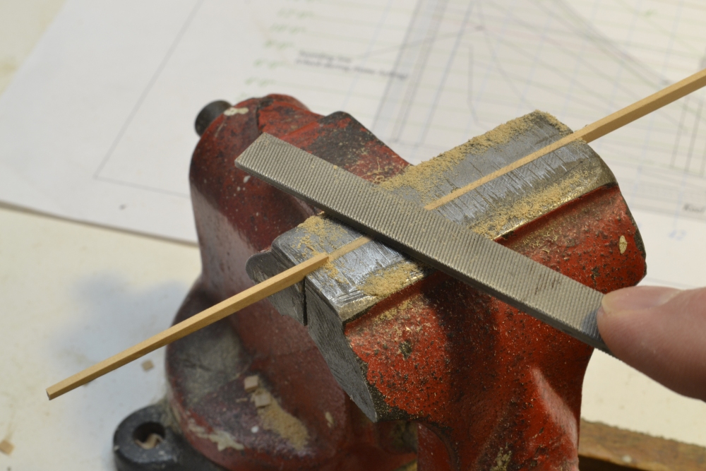
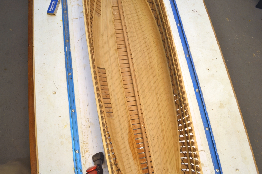
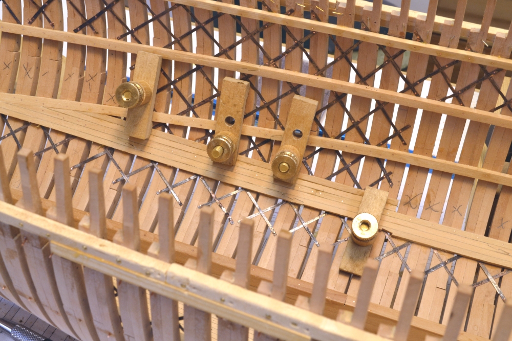
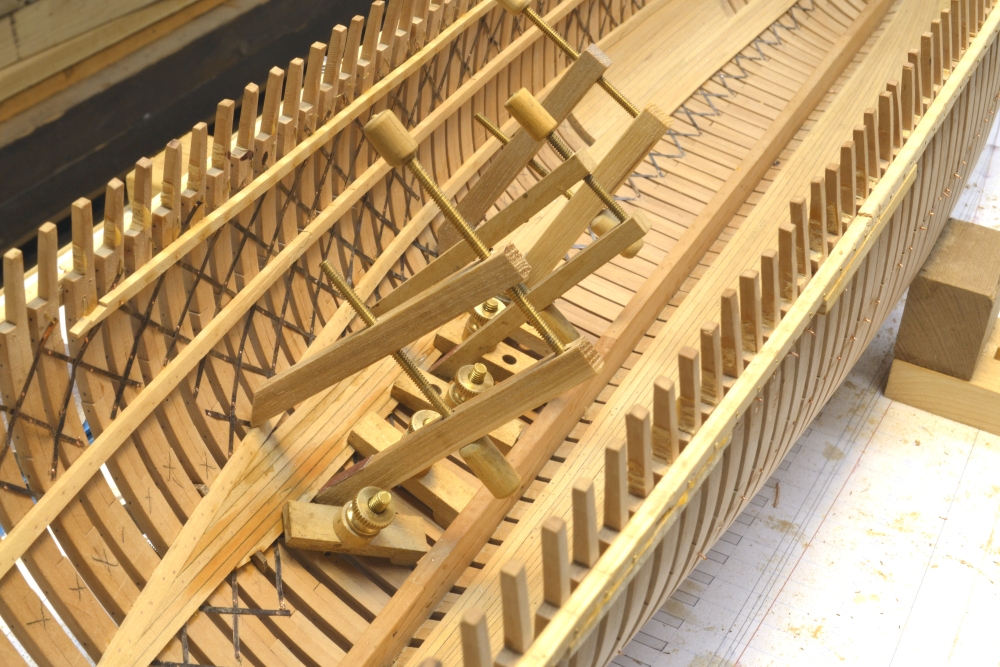
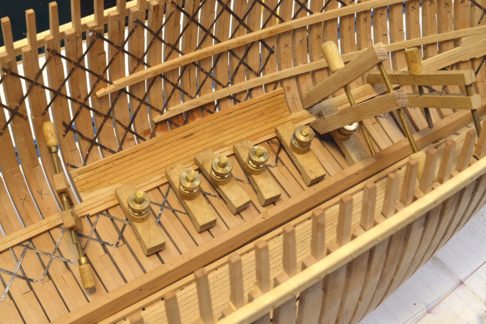
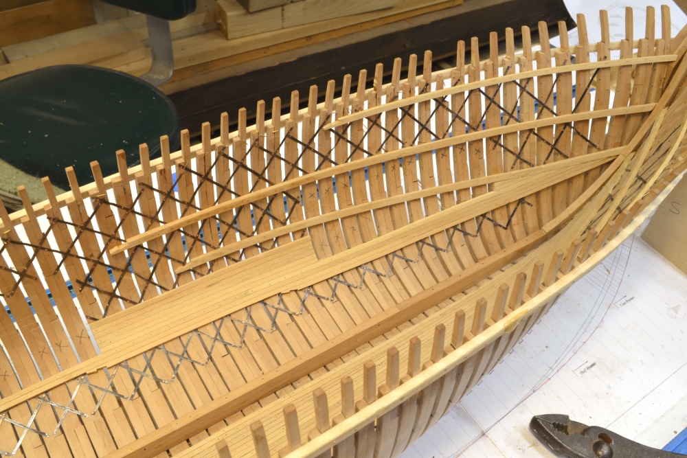
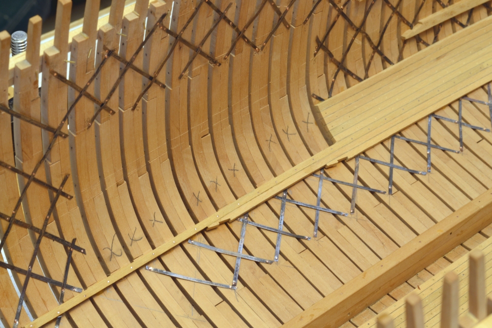
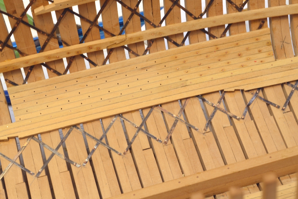
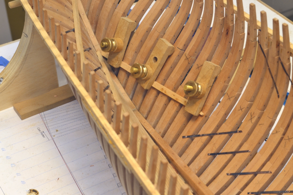
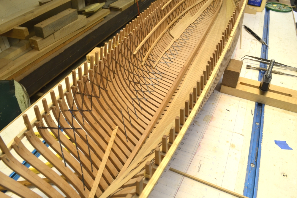
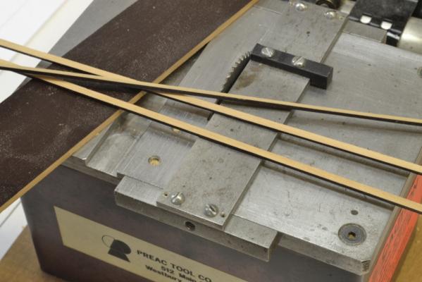
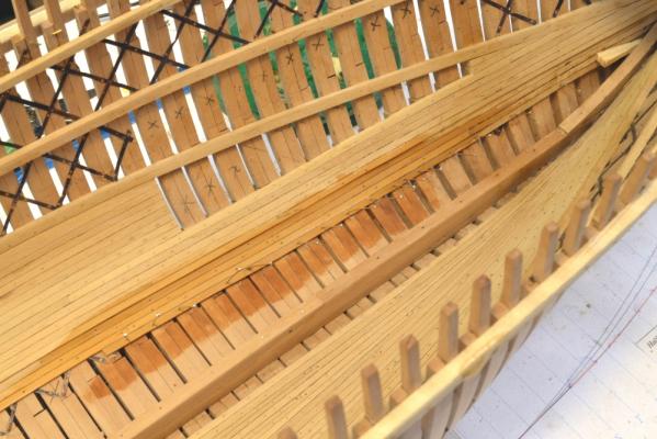
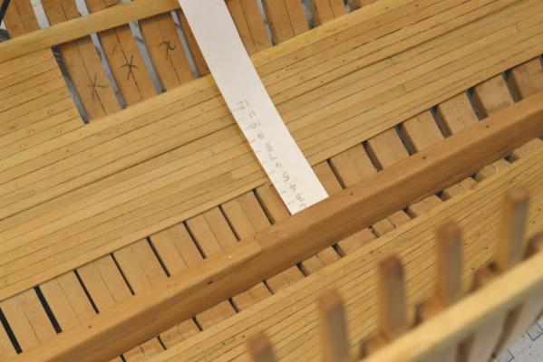
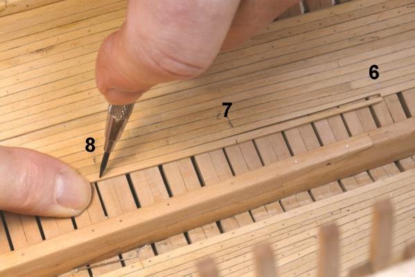
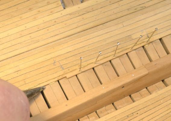
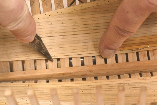
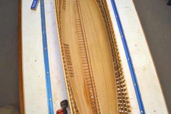
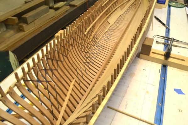
Young America - extreme clipper 1853 Part 52 – Port side ceiling continued The planking of the floor on the port side continues – dull work, but with some interesting quirks as the planking approaches the keelson. The first picture shows some planking strips sawed off of a wide blank of Castelo – a substitute for real European boxwood. I am using Castelo wherever hard or yellow pine would have been used on the original. These planks are 8” wide and slightly over the 4” thick specification. This allows some extra thickness for leveling out and sanding the installed planking. The 4” strips are cut from the 8” thick blank to the left that has been painted with two coats of dark brown acrylic latex paint – ordinary hardware store variety – to simulate the caulked joints between planks. The next picture shows a strake of this planking being installed. After the plank is cut and fit, yellow glue is applied to the top of each frame. Dark glue is then applied to the painted edge of the plank and the butt end. The plank is then held in place at each frame, drilled and pinned. The pins fit tightly and need to be forced into the smaller holes with pliers to hold the piece until dry. The holes will later be used for treenails and iron blunts at the butts. Water is immediately used to brush off excess glue. Because the line of these strakes is closer to the keelson at the fore and aft ends, a number of planks need to be “dropped” so the planking will finish parallel to the keelson at the limber channel. I started dropping planks after a few of the initial strakes were installed over the full length. The next few pictures show – very briefly – how the number and positions of the dropped planks were determined, The process is conceptually simple but can get confusing in practice. I will not try to describe it completely here. As shown in the above picture, the widths of the planks are marked off on a slip of card and numbered from the end. The number of full strakes to the keelson can then be determined and marked at each point along the hull using the marks on the card. The distance between the marks can then be used to set the taper from two planks down to one – thus dropping a plank toward the ends. The next picture shows the marks being used to set the point where the next plank will be dropped. I normally do not drop more than one or two planks in a single strake. The plank has already been tapered to half-width at “6”. It will be notched at the point marked “7”, cut halfway through at that point, then tapered up to full width at the point being marked at “8”. The next picture shows the plank that is being marked above being filed to shape – on the unpainted side. In the next picture this plank is being installed. I hold the plank tight to its neighbor using the pliers as shown in the above picture. The pin hole location is then center-marked and drilled. The pliers are then used to push in a pin and secure the plank. In the next picture the aftermost piece in this strake has been tapered to the “drop” point and is being fit into position The last picture shows the floor after the installation of this strake. A few more planks will need to be dropped before getting to the limber strake next to the keelson. This method was used on the finished starboard side. I usually recheck remark the drop points after each strake is installed. I expect the divergence to be fully corrected before installing the last two strakes. I hope this brief explanation has not been to confusing. Ed

- 3,618 replies
-
- 28
-
-
- young america
- clipper
- (and 1 more)
-
Thank you for this comment, Len. I think sharing methods is one of the best things we can do here. They may or may not be the best for everyone, but readers can decide that for themselves. Ed
- 3,618 replies
-
- 5
-
-
- young america
- clipper
- (and 1 more)
-
Cherry is a beautiful wood in appearance and to work with. For modeling it is best to choose pieces with straight grain. This is not always easy because the grain is often variable. This grain variation is very desirable when used on, for example, furniture. However, the grain variation gives a mottled appearance on small model parts that is not usually desirable. Swiss pear has the advantage of similar color but very straight uniform grain. It is more expensive and less available than cherry. Also the darker shade in cherry is heartwood and the lighter is sapwood. The heartwood is the more desirable due to the color and physical properties. The brittleness mentioned above is due to the grain variation that produces cross grain weakness on small pieces - strips. Ed
-
Guy, Finally, a long overdue visit to check out your build. Looking good. Gluing those cant frames is always a challenge. Ed
-
Thank you for your comment Guy - and to everyone else for the "likes." Ed
-
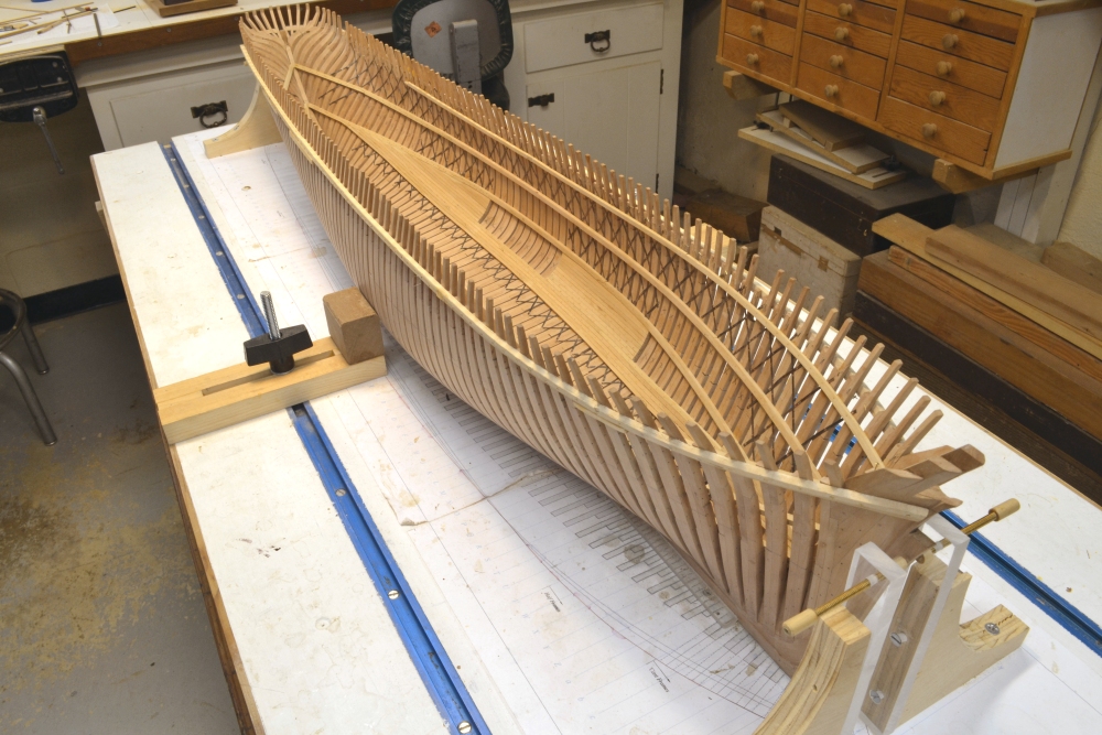
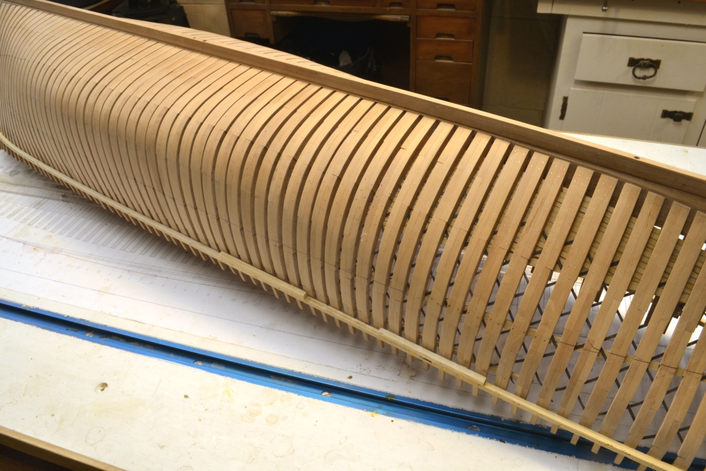
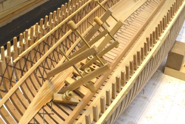
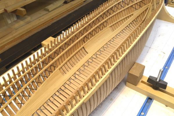
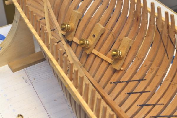
Young America - extreme clipper 1853 Part 51 – Port side ceiling continued It has been about a week since the last post. Seems longer. Work has been progressing, but most of it is similar to work covered in earlier posts, so there has not been much of interest to add. The first picture shows the bilge ceiling being installed under the lower deck clamp aft on the port side. At this stage all of the iron strapping is in place on both sides, so now it’s a matter of keeping it undamaged until it is covered by the various internal planking and clamps. The next picture shows some of the lower strakes of the thick bilge ceiling being installed. A fair amount of clamping is required to pull these 8” x 8” timbers into place and hold them there while the glue dries. The deck clamps have been extended concurrently with work on the ceiling. This can be seen in the next picture, which shows the current state of the model. Below is another view showing the open areas in the bilge ceiling. Later, nine frames in each of these sections and an aft section will be removed up to the height of the middle deck clamps. The entire bilge ceiling is complete in this picture. The thinner floor ceiling planking has not yet begun on the port side. The next picture shows a closer view of the central view port area. All of the bilge ceiling has been leveled out and given a preliminary sanding to allow the remaining iron (copper wire) bolts to be installed. All of the bolts have been installed in the completed deck clamps. The last picture shows the starboard lower hull. In this picture the protruding bolts installed thus far have been filed and sanded off. There are many more to install as the inside work continues. The bolts are relatively invisible at this stage but will be much more prominent when etched black. The next step is to plank the floor area on the port side. Ed


- 3,618 replies
-
- 33
-
-
- young america
- clipper
- (and 1 more)
-
In looking back at some of the posts, I found that many of the images were lost in the last system hiccup. I have now replaced these. I think/hope all have been reposted. Let me know if I missed any. Ed
-
Beautiful model, Nils. Thank you for sharing it with us. Ed
- 222 replies
-
- 1
-
-
- gorch fock
- barque
- (and 2 more)
-
Frank, The heights of the deck clamps (top) are set on lines that follow the line of the deck at the side, minus the depth of the deck beams. The lines of the deck are usually drawn at the underside of the deck plank (top of beam). The lines at the side are lower than the centerline of the deck by the amount of round-up of the deck beams. Deck lines are usually shown as long arcs on the sheer plan, but the YA drawings were made from the original table of offsets that did not include deck heights. I used a secondary source for the heights of these lines along the length of the hull. They do not correspond to the body plan body plan diagonals that I mentioned. Ed
-
Thanks, everyone. Micheal, getting it right around those future view ports has forced me to keep on my toes - so as not to put glue, bolts, wood members or strapping where they aren't wanted. I had to decide exactly the extent of these openings, how they would be reinforced, etc. before starting any work. Even at that there were some moments of confusion, especially with the alignment of the strapping.. Peter, I used "normal" floors on the forward frame of each pair, centered on the keel, with lower futtocks of the aft frames butting at the centerline. I did have to make some assumptions in laying out the lines of the floor and futtock heads. I set these using diagonals on the body plan. Good luck with your quest for data on the schooner. Ed
-
The metal strip is a good suggestion. Another approach to avoid splitting in the outer layers is to use male and female shaped parts to close on the laminate. I have also had success gluing the layers when they are formed using water-emulsion glue - PVA, ie. Titebond. Springback when dry is zero with this approach. Love your work on those metal tubes, Micheal. Ed
-
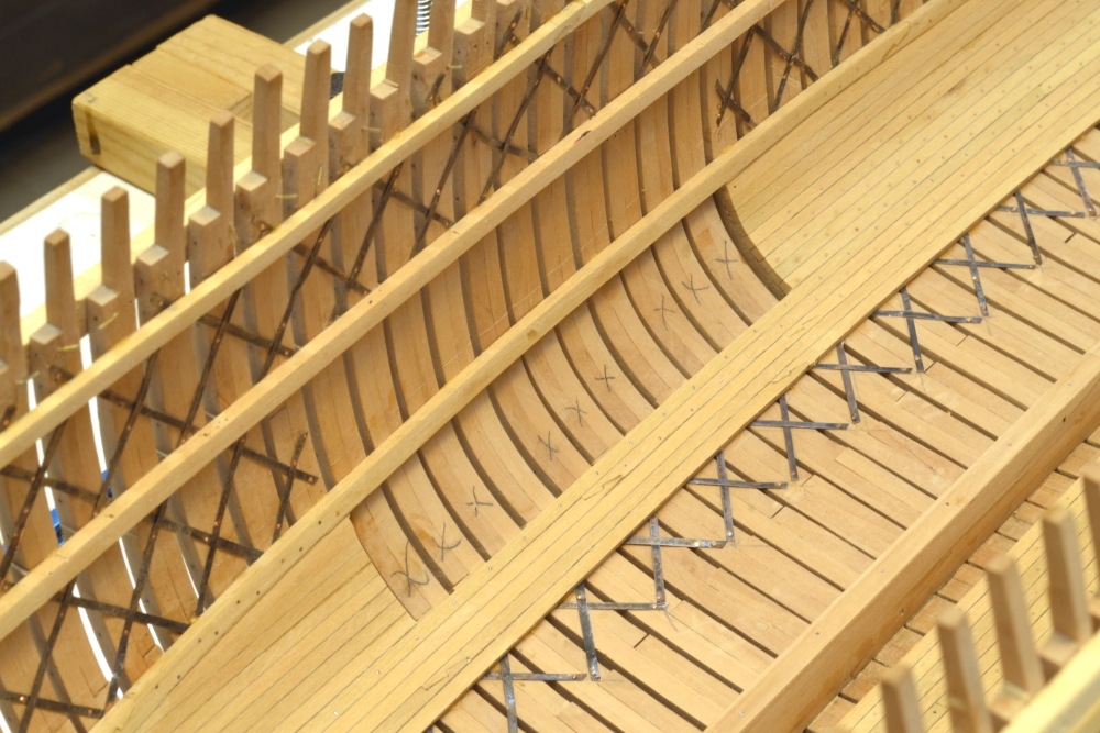
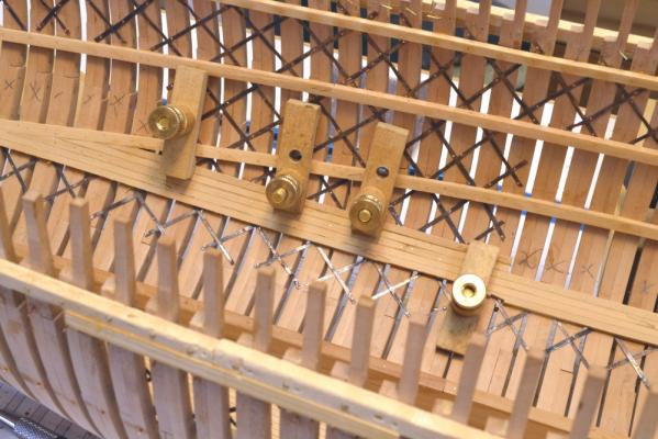
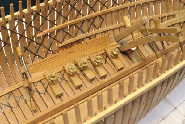
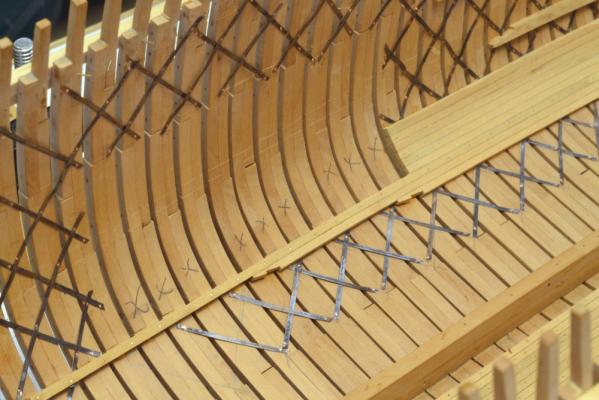
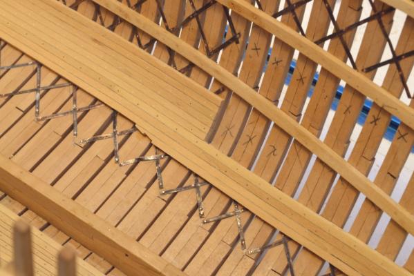
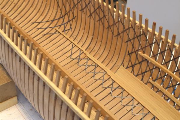
Young America - extreme clipper 1853 Part 50 – Port side ceiling continued In the first picture some of the 8” thick bilge ceiling members between the forward and midship view ports have been installed and one of the lower members is being glued into place. The next picture shows this area a bit later, unobscured by clamping. Strapping installation has been proceeding in parallel and keeping ahead of the ceiling members and deck clamps. The next picture shows the extent of the midship view port – left free of strapping. The members marked “X” will be removed later up to the middle deck clamp. In addition to exposing the inside of the lower hull, the view ports will also show the cross sections of the ceiling and other inboard planking and structural members. A part of the ceiling cross section can be seen below. Below is another view of the port side inboard area aft of midship. Bolting of the bilge ceiling and deck clamps is keeping pace with the other work. The next picture shows the area between the view ports drilled and partially bolted. The bilge ceiling ends are easier to fit after the lower deck clamp is in place. The next picture shows the aftermost section of the lower deck clamp being installed. The strapping is nearing completion in this picture. The next picture shows most of the strapping work completed. A few lower pieces near midship have not yet been installed. The outline of the aft view port can be seen in this picture. Ed


- 3,618 replies
-
- 22
-
-
- young america
- clipper
- (and 1 more)