EdT
-
Posts
2,214 -
Joined
-
Last visited
Content Type
Profiles
Forums
Gallery
Events
Everything posted by EdT
-
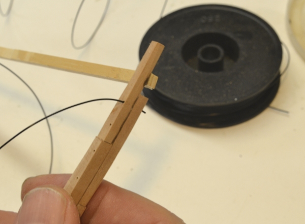
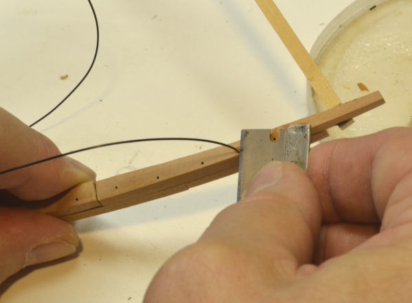
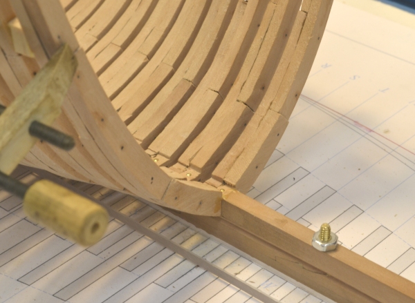
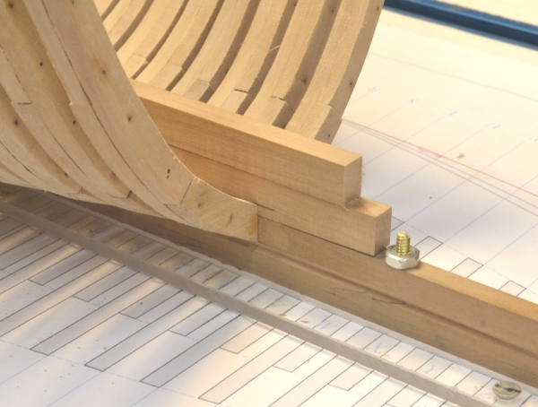
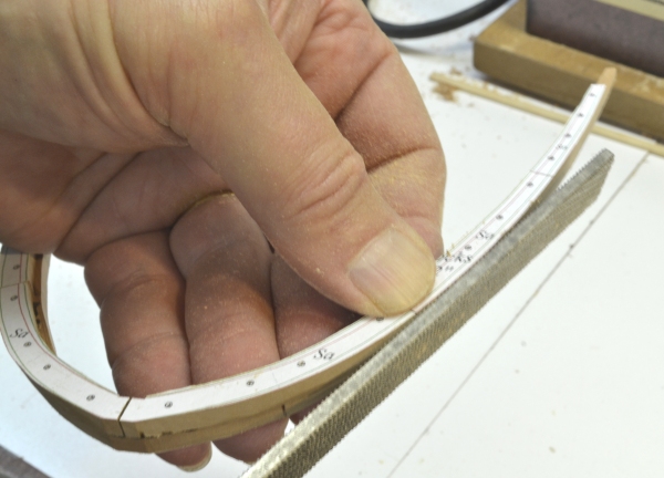
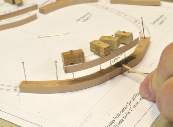
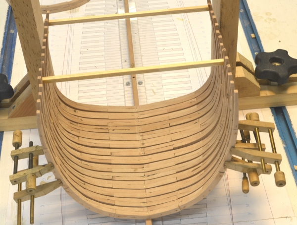
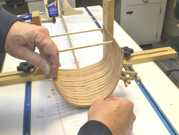
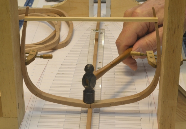
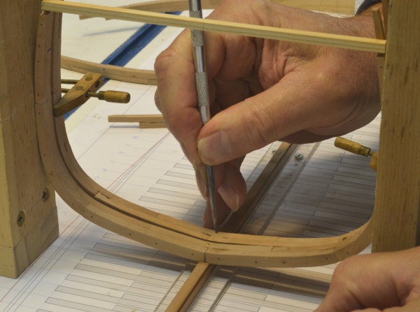
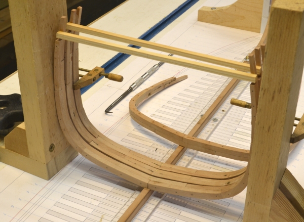
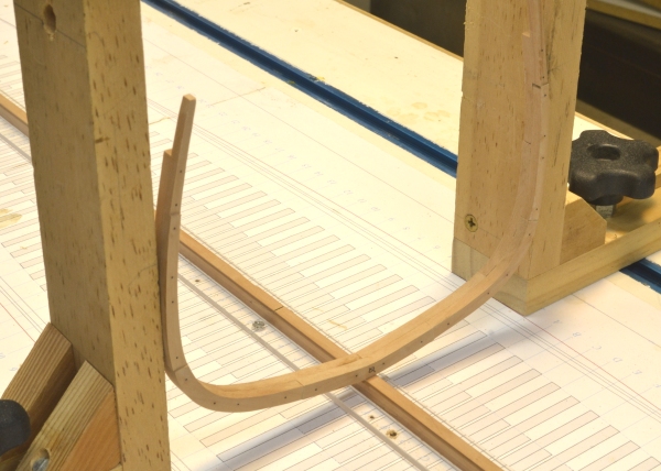
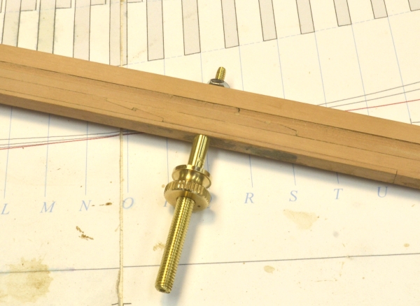
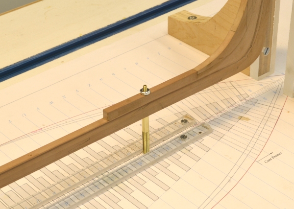
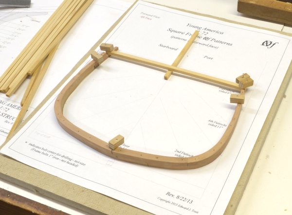
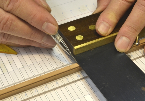
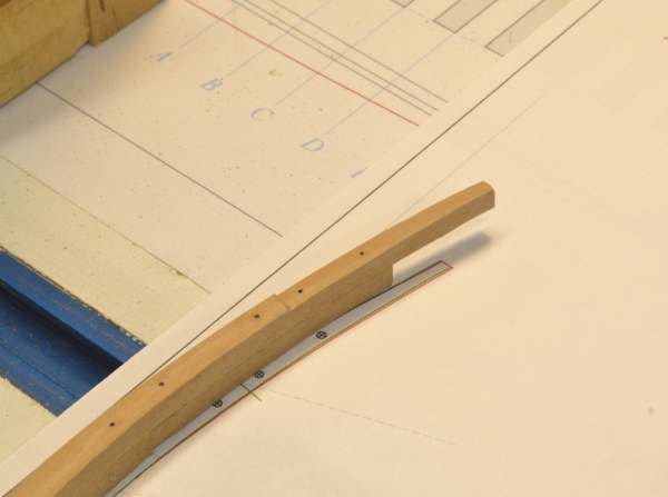
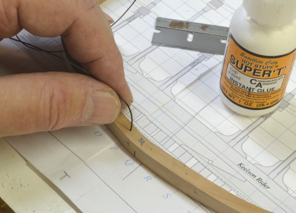
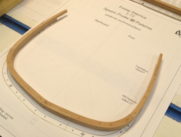
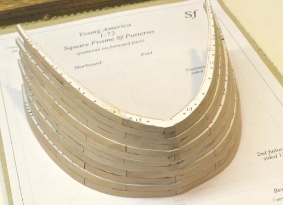
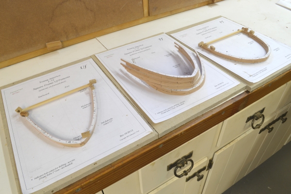
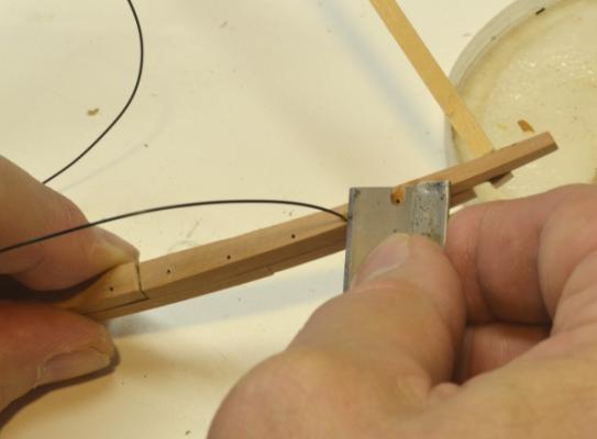
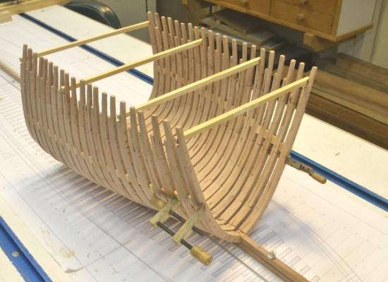
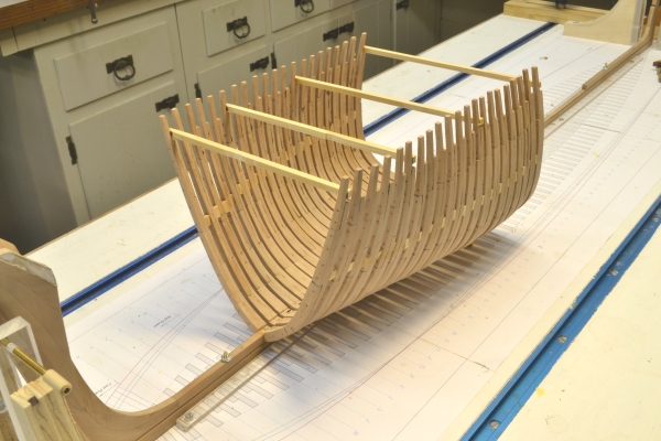
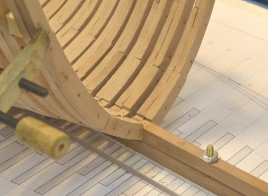
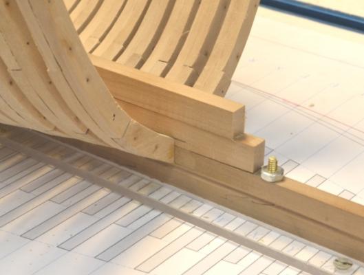
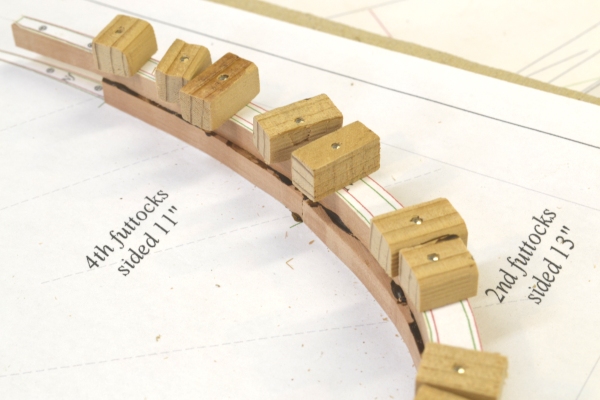
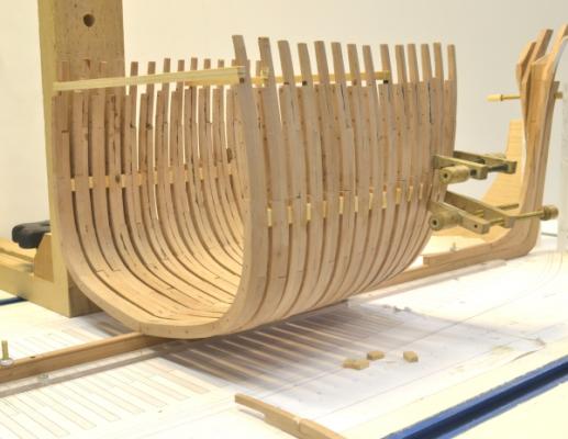
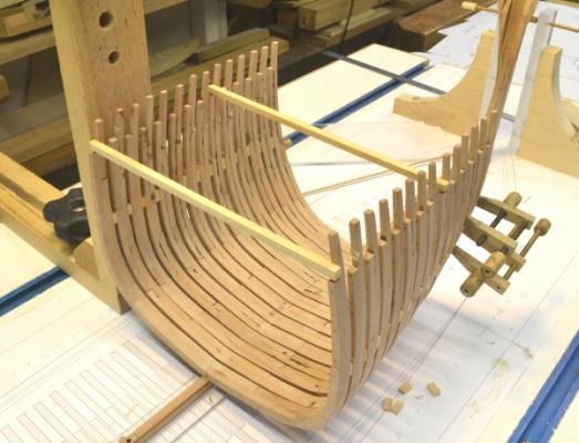
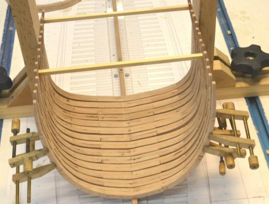
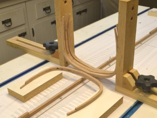
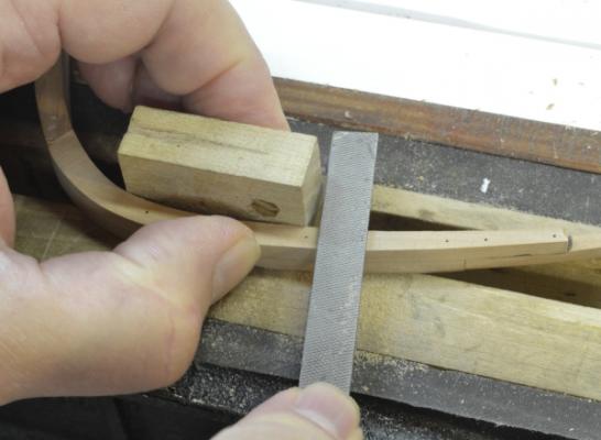
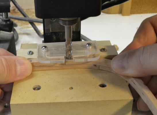
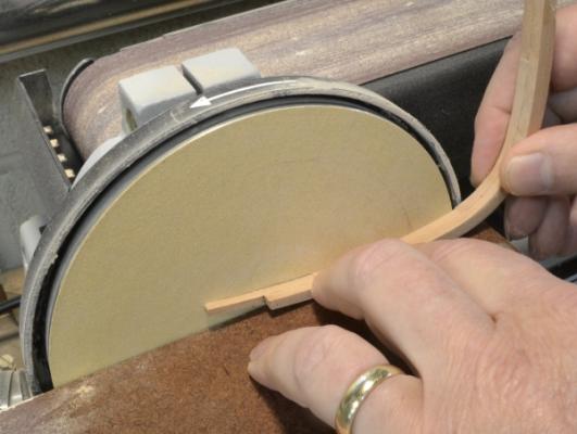
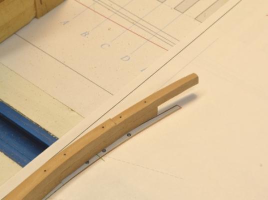
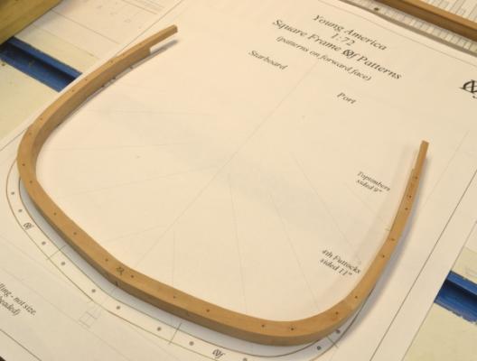
Young America - extreme clipper 1853 Part 19 – Framing Continued American Clipper Note: On her fourth voyage, still under Cressy, Flying Cloud left New York for San Francisco in January 1854 and set a new record of 89 days, 8 hours, just under her 1851 performance. This record would eventually fall to Andrew Jackson in 1859 with a passage of 89 days, 4 hours. This new record would be in dispute for years. These matters were taken quite seriously. Given the vagaries of wind, weather and seasonal variations, one wonders what all this recordkeeping really means. Between 1851 and her last Cape Horn voyage in 1856 Flying Cloud's record to San Francisco included passages of 89, 113, 106, 89, 112 and 185 days. I am getting close to wrapping up the forward square frames. The remainder of these frames – P through U are shown below after beveling as described earlier. The narrowing of the lower hull forward can clearly be seen. The next picture shows the frames with cross-spales being fitted to U and P. The next step was to reduce the sidings of the upper futtocks and toptimbers. This was described earlier. The last step before erection is to install the framebolts. These were 1” iron, unheaded, cut off flush. They are simulated with 30 lb. test black monofilament. After dipping in CA the filament is slipped through the pin holes used for assembly. There were 3 to 4 of these bolts per timber. There are two through the rail stanchions as shown above. After gluing in, the excess ends are easily sliced off with a razor blade as shown below. The next picture shows the remaining forward square frames installed. Starting with frame R going forward the sidings are reduced and the frame spacing increased. For example the floors go from 14” to 12” and the frame spacing from 32” to 34”. Webb used this method to reduce hogging by lightening the forward structure where the hull buoyancy was less due to the fine entry. This design feature was able to reduce the weight of the forward structure by as much as 25 tons in Webb's ships. On the model the spacers have suddenly gotten larger due to the increased separation. The last two are being fitted above. Next, another picture of the framing at this stage. The next picture shows the connection of the last frame, Q, at the keel. There are two points of interest here. First, there is the filler on the keel forward of the last full frame. Frames forward of this one will bolt to the sides of this filler and the keelson/deadwood – soon to be added. Second, notches in the tops of the frames at the keel can be seen. This is to provide additional bolting height for the next few frames which would otherwise have to be bolted only at the lower 17” of their feet – not enough – in my opinion. Additional bolting space can only be added by raising the cutting down line aft of this first half frame. If this were done suddenly at frame V there would be a step up in the inboard planking, so to provide a fair bed for the planks, I started raising the cutting down line four frames aft, adding additional bolting height of about 7" for the first half-frame. The last picture - showing some strips representing the two tiers of the keelson - will help illustrate the above issue and also show the huge size of the keelson. These two 16”w x 24”h tiers ran in a straight line from stem to sternpost, bolted heavily through the frame floors to the keel. I have placed a pencil mark on the lower keelson to show the raised cutting down height. This additional height will allow one of the horizontal bolts for the first half frame to be driven through the lower keelson. The model mounting bolt and nut is about to be set into the actual lower keelson once the forward end of that that is fitted to the apron and marked for length. Ed

- 3,618 replies
-
- 13
-

-
- young america
- clipper
- (and 1 more)
-
Yes.
-
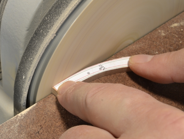
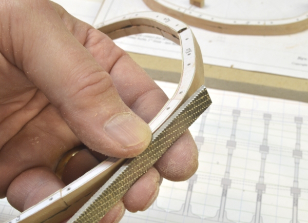
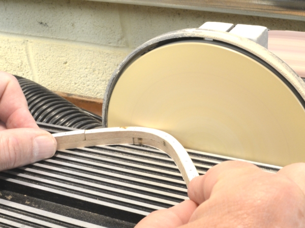
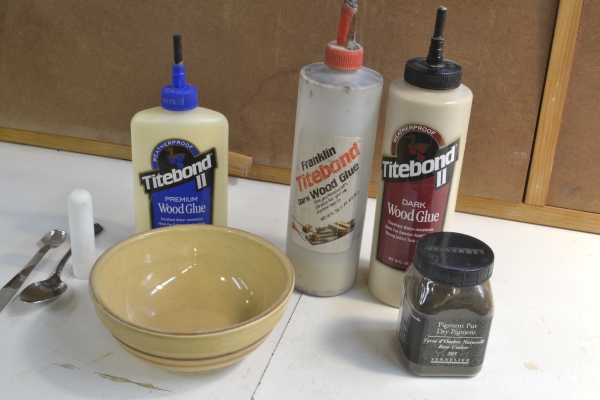
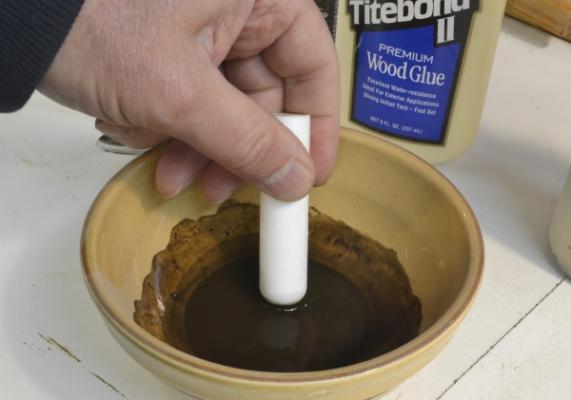
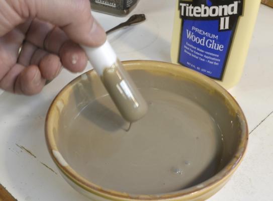
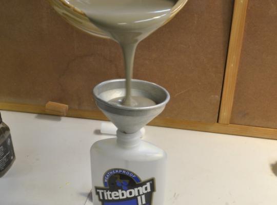
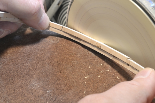
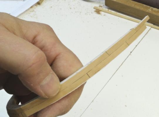
Young America - extreme clipper 1853 Part 18 – Framing Continued American Clipper Note: Flying Cloud was launched from Donald McKay’s yard at East Boston a month before Challenge. She was of comparable size, and like Challenge, bound for California from New York on her maiden voyage. Inevitably she was drawn into the great “challenge” surrounding the ship Challenge. She left New York in early June 1851 under command of Josiah Cressy. Three days later she lost her main and mizzen topgallant masts, but reached the line (equator) in 21 days. She arrived in San Francisco in 89 days 21 hours, beating the previous record of 97 days, set by Sea Witch the year before – and 18 days under the Challenge’s ill-fated maiden voyage performance. After the last post, there was a question about the dark glue that I use to highlight structural joint lines. The 8 oz. bottle I mixed up for Naiad was just about empty, so when replacing it I took some pictures to help answer the question. The first picture shows the starting point, plus two bottles of ready made dark Titebond glue. The new bottle to the right is the currently available dark Titebond II. I find it a bit light for pear. The old – quite old actually – bottle in the center is the old Titebond dark glue – just about the right shade but no longer available. T the left is an 8 oz. bottle of the standard yellow. (The first thing I do with a new bottle of Titebond is pull off and toss the sliding top, cut off the closing nib and insert a length of plastic rod that is easy to remove and replace and does not clog up.) At the front right is a jar of raw umber artist grade pigment that will be used to darken the glue. This bottle is several lifetimes’ supply. In the next picture, about a teaspoon of dry pigment was added to about a tablespoon of water and is being thoroughly mixed with the pestle-like Teflon rod until there is no sign of powder or lumps. The entire 8 oz. of glue is then added a bit at a time and mixed in. The next picture showsthe final appearance. In the next picture the empty bottle has been thoroughly washed out with hot water and is being refilled with the darkened glue. I expect this will be enough to finish the model. The next picture shows the last of the full forward square frames. The rail stanchios are about to be installed. The frame is now ready for beveling. In the next picture the forward face of the pair is being trimmed back to the forward profile line on the disk sander. The aft outer profile was previously trimmed back. The disk is kept away from that line in this step. This leaves a hump or ridge between the two profiles. The next picture shows this being removed by hand with a flat Rasp. The last picture shows the resulting bevel. The insides are only roughly beveled – mostly using a spindle sander. They could be hand finished as well, but I intend to do that after the hull is assembled. The final bevel will be refined when the hull is finished sanded. Beveling these pairs before assembly saves tedious sanding work later, makes frame erection easier and yields a more accurate hull profile. There is still some work to do on these frames before erection. Ed


- 3,618 replies
-
- 13
-
-
- young america
- clipper
- (and 1 more)
-
Again, thank you all for the supportive comments. Allan, sounds like a good project. The full framing would give you a chance to exercise those TurboCad skills as well. Anyway, I am glad to hear of your interest. I have been hoping the YA build would attract some from the fully-framed set. The framing is different from the 18C RN. It is alot simpler - no chocks, standalone frames, jogged or curved toptimbers and no ports to contend with. At the same time there is more of it. There are also more judgements to make on design specifics. Although quite a lot is known and documented on the general construction, specific ship structural details have been lost. Good luck. Let me know if a novice can help. Bruce, the framing is going faster than I expected. I spend on average 2-4 hours each day in the workshop, often in more than one session. I also spend time outside the shop - on research, drawings, photos and this blog. When I start to tire, I quit and do something else. The Sovereign / YA race would have been interesting. In reading the endless accounts and passage times for these various ships and routes, it appears to me that the abilities of the captains and the vagaries of the weather - especially time of year conditions - had as much to do with performance as the differences in the ships in this class - probably more. Variation in sailing times over the same routes are considerable for the same ship on different occasions. My impression is that Babcock, YA's original skipper, may not have been the man to beat Sovereign. On that first 110 day voyage to SF, it seems he made some judgements that extended the time, but I have not dug into that. Your comment on the iron strap bracing caught my attention, particularly your positive statement that it was on the inside. I am inclined to agree, but in scouring every source I can find, have not found a definitive reference. On Crothers Challenge drawing, dated 1975, it is clearly shown and noted as on the outside - the so called Lloyds system. By the time of his book (1997) he seems to have backtracked and is not sure. Most of the ships he lists have the bracing on the inside - the Admiralty system. But none of those are Webb's. He discusses all this. I believe by the 1860's the American Lloyds registry specified outside, but in the 1857 registry inside bracing is specified. Structurally, outside bracing is better, but more troublesome to install. I do plan to install this and am leaning - currently - to inside. However, my question is, do you have a reference for this? It is unfortunate that Great Republic, as designed never got a chance to show her performance. After the fire - before her first voyage - she was cut down and given a smaller rig - but was still a good performer. Young America also had a very long - and essentially trouble-free - career of 32 years with the 50 punishing Cape Horn passages before she was mysteriously lost on her way to Trieste from Phialdelphia in 1885. Thanks, again, for your interest and comments. Daniel. I made some new dark glue and will show some pictures in the next part. Ed
- 3,618 replies
-
- 5
-
-
- young america
- clipper
- (and 1 more)
-
Thanks, again, everyone. I am really looking forward to seeing the full hull in frame. The bare frames really let you visualize the shape. Daniel, there is no secret to the messy process of making the dark glue - if you have Naiad Volume I (subtle hint). The process is simple. I use dark brown artists' pigment. Mix it well with maybe a tablespoon of water - less than a teaspoon of pigment will do - to obtain a dark liquid - no powder or lumps visible. Add this to a six ounce bottle of PVA (I used Titebond II) and mix it in thoroughly in a bowl - a mortar and pestle type of mixing - until it reaches a smooth syrupy state - about the color of chocolate milk or darker. Wash out the remaing white glue in the bottle and refill it with the dark glue. One 6-ounce bottle saw me completely through the Naiad project. My glue is very dark and could be lighter with the same effect when dry. I have had no problem with adhesion. I am about to make a new batch so I will include some photos. Good timing on the question. Ed
- 3,618 replies
-
- 3
-
-
- young america
- clipper
- (and 1 more)
-
Bruce, I read about Lightning's butchering by her new owners. Its hard to imagine doing this to a ship after such a successful opening performance, but I guess design dogma and transatlantic builder rivalry can explain a lot. The location of the maximum breadth is an interesting design topic. I am sure you have seen the table in Crothers's book on this. It shows a clear difference of approach between Webb and McKay, with Mckay placing this back close to the midline of the hull and Webb placing it far forward. According to Crothers' table Lightning, as you say, had it 1'3" forward of mid-length and Young America 25' forward of it. Their other ships followed suit. On Sea Witch, the one Griffiths example in the table, it is placed 14' 9" forward. All of this seems to demonstrate that hull design was still an art form. I don't know, but I guess that heavy weather performance may have been helped by the long length of these ships. Also, I guess if captains were piling on sail even in heavy weather - at risk to the ship, of course - their heavy weather performance would look good. An interesting topic. Maybe some re-reading of Chapelle and MacGregor is in order. Thanks for your comments and your resurrection of the Lightning log. By the way, that figurehead is priceless. In a garage? Ed
-
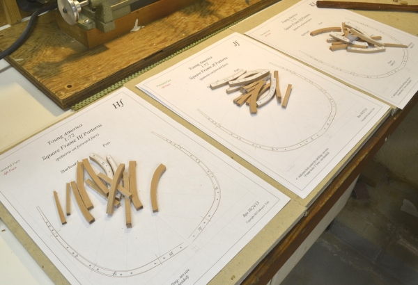
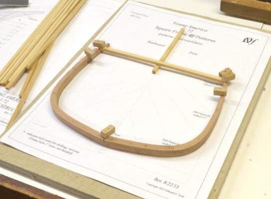
Young America - extreme clipper 1853 Part 17 – Framing Continued American Clipper Note: Webb’s 1851 clipper, Challenge, was one of the most extreme of designs, with a dead rise of 20 degrees at midship, plus the usual narrow entry and run. Her owners wanted no expense spared to make her the fastest and finest of merchant ships. The legendary Robert Waterman was to be her captain and came on early to supervise construction. Typical of most sea captains given the opportunity, he fitted her with too large a rig of spars and sails that, if anything, detracted from her performance until later replaced. Expectations ran high for her first run to California, with $10,000 offered to Waterman to do it under 90 days. It was a disappointing passage. Waterman, a hard case in a profession of hard cases, had crew problems almost immediately. Off Rio, the mate was stabbed and mutinous members of the crew flogged. Later three men were blown off the mizzen topsail yard and a further four died of dysentery. Upon reaching San Francisco in 108 days, the crew and press provoked sensational riots against Waterman. He was later cleared of wrongdoing but Challenge went to a new commander. Her troubles continued. Framing is moving ahead at a faster clip than I anticipated. I have moved up the learning curve and learned the little secrets that make the new pin-indexed assembly process work. You will recall that the bolt/pin holes are indexed to identical positions on both frames in the CAD lofting process. After cutting and trimming the parts, only about 30 minutes are required to complete the assembly of a frame pair. This does not include beveling, milling the sidings or bolting – and I am not pushing the pace. The next few pictures illustrate some frame assembly steps. The first shows how the pins are used to place the frame timbers – pattern side down - on the assembly pattern. Pin holes were drilled using the pattern marks on the underside of these pieces. Accurate timber end trimming and vertical drill centering are key. Although the outer frame profiles are sanded back to the pattern line, only the pins are used for alignment. The next picture shows a lower futtock being glued into place – again relying entirely on the pinhole locations. After slipping the pins through the timber they are pushed into the holes in the lower pieces before gluing. Dark glue is then applied as shown and the upper part pushed down and “nailed” into place with the pins and wood block buffers. The next picture shows the amount of offset in the fore and aft timbers of the beveled pairs. This offset increases going forward. I am not cleaning off excess glue because I do not want to damage the patterns with water. There are patterns on both sides of the frame pair and they are needed for beveling. The inboard side will be beveled back to the red line on top of the pair. The glue will come off when beveling. I described the beveling, siding and bolting process earlier. The next few pictures show progress in erecting the frames. In this picture the first 14 pairs have been installed. This picture shows a characteristic feature of clipper hull shape. The deadrise of the timbers is increasing going forward, narrowing the lower part of the hull. The top timbers, however remain at almost full breadth to provide adequate floor space on the forecastle for crew activity. Eventually the forward shape will flare out at the top over the very sharp entry below. This is a very different hull shape from Naiad. All these pictures show temporary pine spacing chocks being glued between the frames above the lower futtocks. This provides strength and helps maintain alignment. Later when all frames are in place, these will be replaced with temporary ribbands – probably at the height of the planksheer. These will bring the toptimbers and rail stanchions into a final fair line and hold them in place until permanent rails are installed. The last picture shows the 15th frame (O) being positioned for drilling of the pin/bolt hole into the keel. Time to start cutting out more frame timbers. Ed


- 3,618 replies
-
- 20
-
-
- young america
- clipper
- (and 1 more)
-
Fantastic work, Bruce. A beautiful model of a beautiful ship. Ed
-
Right you are, Bruce. I have the plans for Lightning and also Challenge and both show a lot more structursl detail. I have assumed that YA would be quite similar to Challenge, since Challenge was quite successful and they were but two years apart - and of course by the same builder. Crothers actually endorses this view, so I felt on safe ground. Webb killed a lot less trees than McKay, but the ships held up as well. I will discuss some of those differences in later posts. The 30 year life and the 50 trips around the horn for YA caught my attention as well. I also liked that Webb considered her his masterpiece and that she was his last extreme. I am sure you are right about the number of frames vs, a three decker. The latter type generally ran around 180 feet in length, whereas clippers like Challenge and YA were in the 240' ballpark. Webb used variable frame spacing between 32 and 36 inches. Room and space on a RN three decker was around 34 inches, so the frame spacing was quite similar - but of course there were more on the longer ships. Can't comment on the amount of timber vs. a two decker, but your statement doesn't surpise me, especially if you consider some of McKay's and others' gigantic multi-tiered and multi-sistered keelson assemblies - to say nothing of the typical bilge keelson and oversized waterways and clamps. These ships were built. I look forward to following your rigging of Lightning. Ed
- 3,618 replies
-
- 1
-
-
- young america
- clipper
- (and 1 more)
-
Thank you, Mark. I really appreciate the comments on the book. If someone with your skills can learn something from it, it was worth the effort. Thanks again. The new build is off to a good start and an interesting project. Many things different - and some new methods emerging as well. I know the dilemma aligning those pump cisterns and also all the shaft rhodings. Yours look terrific Ed
-
Looking good, Mark. Glad to see you back. Ed
-
I'm glad to see you posting this build, Bruce. Looking forward to it. Ed
-
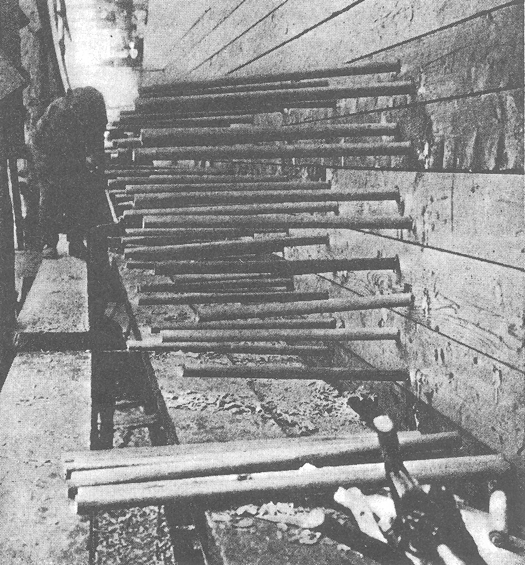
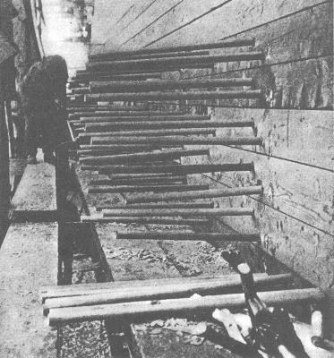
Thanks for these comments. Bruce, I am using the Crothers plans for Young America only as a reference for the detailing that will be done later. The plans do not show much structural detail. My primary source is the original table of offsets, plus structural information from Crothers book, The American Clipper Ship, and a number of other sources. I will create a full set of plans with patterns based on that. Crothers' Sea Gull Plans are excellent, but they are of limited use for the structural model I am building. Daniel, the diagrams are quite interesting. Thank you for posting. Are they from a specific country? I like the detail showing the wedge set into the bottom of the blunt. I believe practices varied and evolved - with a general trend toward iron, copper and mixt metal - especially for structural uses. For the American clipper period, my understanding is that after thorough drying, treenails were formed as straight cylinders from the upper branches of locust trees - noted for hardness and straightness of grain. These were sold commercially by specialist suppliers. Used mainly for internal and external planking, they were driven into slightly undersized holes. The exposed end (or ends) were then opened with a chisel tool and wedges driven in. I do believe - as shown in your diagram - that for planking they were usually driven through after both inside and outside planks were installed. Since this planking was not installed together, a certain numbers of blunts - driven 2/3 into the frames - were used to hold the planking until the final treenails could be driven through. Attached is an photo showing planking treenails waiting to be driven in - probably late 19th C - from book Wooden Shipbuilding by Charles Desmond. Rob, a variety of fastener types were used - iron copper and wood - some as blunts driven in partially, some rivetted on the ends, with or without washers. Some were flush, some with rounded heads, some counterbored and plugged. You name it. Wood treenails were used right up into the 20th century on wood ships. I believe you will find specifics on types on various ships in the tables in Crothers book. Thanks, again, guys. I appreciate the input. Ed
- 3,618 replies
-
- 6
-
-
- young america
- clipper
- (and 1 more)
-
Thanks, Elia. I don't know when or if I will run out of these anecdotes. I keep jotting them down when I read them, You can't make this stuff up. A very interesting period. Ed
- 3,618 replies
-
- 1
-
-
- young america
- clipper
- (and 1 more)
-
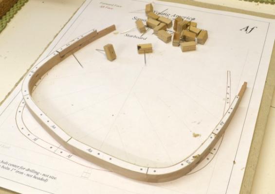
Young America - extreme clipper 1853 Part 16 – Framing Continued American Clipper Note: In June 1856, the clipper Rapid, Captain Winsor, left New York for San Francisco, followed four days later by Intrepid and Neptune’s Car. Some weeks later Rapid was battling hurricane force winter storms off Cape Horn. Making no progress for weeks, with most of the sails gone, ten of the crew dead, ten more disabled below deck and only four frozen souls to work the ship, Winsor turned back for Rio. He soon came in sight of one of the other ships, hailed her and got no response. It was probably Neptune’s Car. Facing the same conditions, her Captain Patten was confined below, having been struck deaf and blind. With the mate in irons for insubordination, Patten’s 19-year old wife, a capable navigator, took charge of the ship and brought Rapid into San Francisco, 134 days out, 11 days before Intrepid. Where’s Hollywood? Back to Young America. Progress continues on the frame fabrication and installation. The first picture shows the first 7 frames, 0 to F, installed. The next picture shows parts for the next few frame pairs cut out, trimmed and waiting for assembly. After cutting out on the scroll saw, each part is trimmed using the disk sander. First the ends are sanded back square to the pattern cut line. The outer profile is then sanded square up to the outer line as shown below. In the case of the forward frames this is the aft – red – line. From printing a frame pattern to all pieces cut out and trimmed takes about 30 minutes. Average time to loft the two patterns is also about 30 minutes. So up to the point in the second photo, about one hour is invested in each frame pair. I have not timed the remaining steps yet. The next picture shows the amount of bevel starting to appear in the frames forward of midship. After assembly each pair is beveled to the forward outer profile using the disk sander – but staying away from the previously trimmed profile on the aft face. The resulting unsanded hump is then removed by hand as shown below. A flat rasp is being used for this followed by a 120 grit sanding block if needed. The bevel is trimmed back to – but not into - the line on the pattern. Final sanding of the hull will remove the last bit, any glue line residue and will smooth the frames. At this stage - before assembly - most of the external beveling on each pair is complete. The inside has been left somewhat fuller, so more internal sanding will be needed. After this step the patterns are removed from both sides, the sidings of timbers machined back and the bolts added. The pair is the erected. The next picture shows temporary pine chocks being installed between erected frames. These chocks will align the frames and strengthen the assembly, which is rather weak with only the small glued area and pin on the keel. The next picture shows the assembly during the addition of these chocks. As each chock is added, the joint line is plumbed to the line on the base drawing and the breadth is matched to the maximum breadth line. Progress at this point: Pairs 0 to F set, 0 to J fabricated, 2 to U lofted. Keeping these progress measures helps keep me focused on what is a lot of repetitive work. Ed


- 3,618 replies
-
- 18
-
-
- young america
- clipper
- (and 1 more)
-
Wood treenails, and copper and iron bolts were used in these ships. Iron and copper go back to the 17th century. Generally, in these ships, metal was used for structural connections - copper where exposure to seawater was expected - usually below water - or where there was contact with copper or brass - for example plating.. Treenails were used for planking - internal and external - and for deck clamps, waterways, etc. Some of the bolts were very long, precluding the use of treenails. Treenails in American clippers were locust - in England oak. Bolts of all types were driven into holes about 1/8" smaller than the bolt or treenail diameter. Metal bolts were driven in some cases as "blunts" - like long nails. Often they were clenched or rivetted at the ends - raised or flush - with or without washers, In rivetting, an expanded head was formed on the end, in place, with a hammer. Often, usually on deck planking, iron blunts would be counter bored and covered with wood plugs. On Young America I expect to model all of the visible - and some of the invisible - fasteners authentically. The copper content in these ships was considerable - and valuable salvage. Ed
- 3,618 replies
-
- 2
-
-
- young america
- clipper
- (and 1 more)
-
Thanks, guys. Good question, Walt. There were a number of different ways this was done. I believe it was most common to bolt through every floor timber - the forward member - through the keel with copper bolts riveted or clinched at each end. The lower keelson could be bolted through the floors and the keel in the same way, Since the floors were 14" wide, there was plenty of room for this. The upper keelson was often secured with long iron blunts into the keel and through the lower keelson and the frame - perhaps through the lower futtocks - the aft members of the pair. In some cases these futtocks crossed the keel (but not in my case) I have not tried to duplicate any one system, since all this - except for the bolts into the upper keelson - will not be visible. In any case, Young America's details are not known, but it is a safe bet that the upper keelson - visible bolts - would have at least one for every other frame. That will come later on the model. I expect I will have an iron bolt in the upper keelson at every frame. These bolt arrangements had to be carefully laid out to avoid hitting previously installed bolts. There were a lot of bolts. Ed
- 3,618 replies
-
- 2
-
-
- young america
- clipper
- (and 1 more)
-
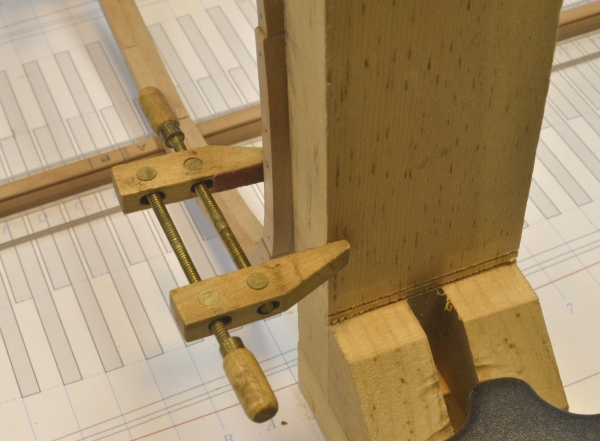
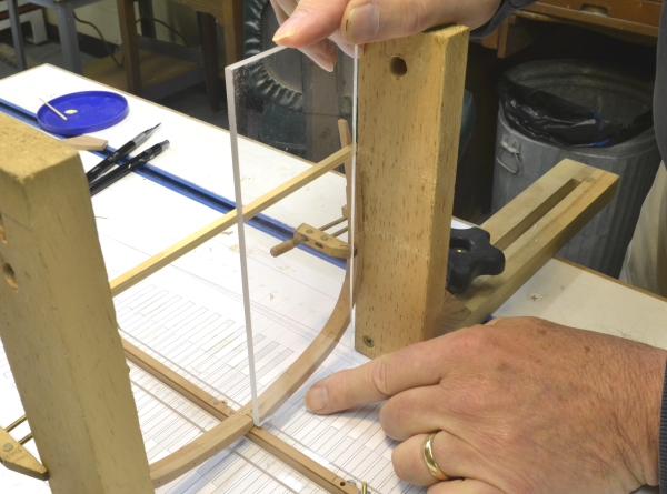
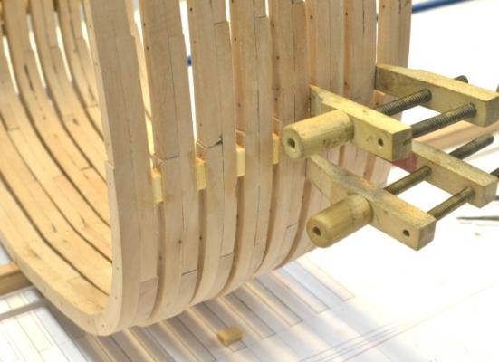
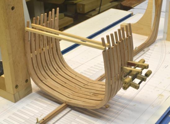
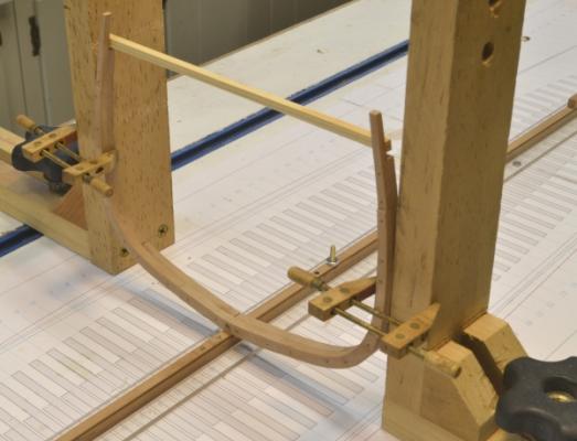
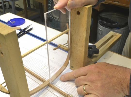
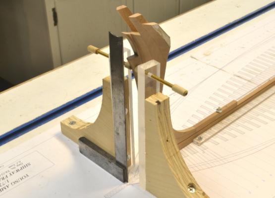
Young America - extreme clipper 1853 Part 15 – Setting Midship Frame Pair American Clipper Note: In March 1849, the telegraph watcher at Sandy Hook, NJ, observed a large ship approaching from the southeast. It could only be a tea clipper, but the first of these for that year was not due to arrive for at least two weeks. It turned out to be Sea Witch, an early extreme clipper designed by John W. Griffiths, under Captain Robert Waterman, just 75 days out from Hong Kong, a west bound journey to New York of 14,500 miles - establishing the first permanent sailing record – never to be beaten by a sailing ship. Her average speed: 193 miles/day. Later in the year, Sea Witch set the standing record from Canton to New York, a slightly longer passage, in 77 days. Hong Kong – New York – Canton – New York in one year – unheard of. Back to work. The first picture shows the setup for erecting the square frames. In this picture the midship frame is held in position for attachment to the keel. The two clamped squares hold the frame at the sides and will maintain pressure on the glue joint at the keel. The squares are clamped at the breadth to the frame with the corners set at the joint line as shown below. The joint line of the pair is aligned with the edge of the square – held by clamps. At this stage the mark at the center of the cross-spale is centered using the Plexiglas rectangle. This gauge was cut square and notched to clear the keel. With the clamps tightened, the bolt hole through the floor into the keel is drilled. A brass “bolt” is then tapped in slightly. The frame is raised slightly to apply glue, then lowered and the position rechecked. The “bolt” is then driven in as shown below. The next picture shows the installed frame later with the clamps cleared away. This is a good time to recheck the center mark on the cross-spale – without the clamps. The next picture shows the bolt hole center being marked on frame A. The last picture shows the first three frame pairs erected. A cross-spale was added to pair A because it was slightly off-pattern at the top. The frames need to be correct at the breadth to use this method. B was OK. Frame C is ready to be set in this picture. Progress at this point: Pairs 0 to C set, 0 to G fabricated, 0 to K lofted. Ed


- 3,618 replies
-
- 16
-
-
- young america
- clipper
- (and 1 more)
-
Remco, you must have some kind of magical powers to keep the frames aligned during construction without a building board. How do you do it? Also, we must be polar opposites. I work mostly standing up and my workspace is usually a mess. Ed
-
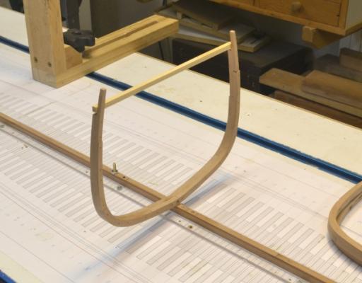
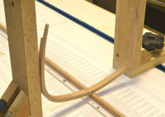
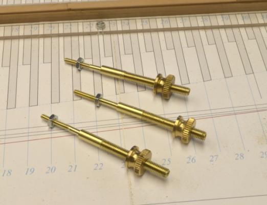
Young America - extreme clipper 1853 Part 14 – Setting Frames – preparation American Clipper Note: Young America cost $140,000 to build. Gross revenue from her first voyage from New York to San Francisco was $86,400 – more than half her initial cost in her first four months! With four frames finished and a few more in progress, it was time to start thinking about erecting them. The first picture shows the midship frame set up temporarily on the keel, supported by the two clamped squares set at the maximum breadth line on both sides. The so-called "midship" frame is set at the deadflat location along the keel. This is not at the midpoint of the hull, but is actually about 20’ forward of that point. Also, this frame is the widest part of the hull only in the neighborhood of the load waterline. At topside the frames immediately aft are wider and at the bottom the frames immediately forward are wider. This is a departure from normal 18C RN practice where the midship frame was the widest at every height. Before setting any frames, some other work had to be done. First, the keel had to be bolted securely to the shipway. The next picture shows the three bolts made for this purpose. These are identical to the type used on Naiad. The reduced diameter section fits up through the keel. It is stopped at the bottom of the keel shoe by the shoulder at the change in diameter. This limits the distance the bolt can be screwed into the model, preventing the keelson from being popped off by over tightening. The small threads are 4-40 and the larger 10-32. The next picture shows one of the bolts pulled up at the keel bottom by the small nut on top, With the top nuts on the three bolts tightened up, and larger holes drilled through the shipway, the keel is slipped into position as shown below. Thumbscrews with lock washers are then tightened up under the shipway. Eventually the top nuts will be filed to fit within the woodwork and the top of the studs will be filed flush to the nuts. These will be covered by the keelson or deadwood. With the keel secured, the end posts were set up in the vertical position as shown below. The next picture shows three frames set loosely in position and a fourth lying flat where it would have been assembled in the real shipyard. At the yard, once the midship frame was set, moveable assembly platforms were constructed fore and aft. Working two at a time, frame pairs were assembled on these then raised up into position. The platforms were then moved and the work on the next frames begun. Methods like these enabled these ships to be constructed in 3 to 6 months – some in less time. If there were two of me I could duplicate this practice. The next picture shows the midship frame being prepared for installation. A pine cross-spale is being glued to the toptimbers to hold the correct upper separation. Also, while in this position, an alignment centerline is marked on the spale with a razor blade. This will be done to perhaps every 4th or 5th frame – plus any that need it – until some other means of holding frame alignment is installed. Finally, the fore and aft faces of the first several frame pairs were squared up from the base drawing and marked in pencil on the top of the keel as shown below. The frames will be glued to the keel based on these marks – and of course plumbed and aligned. Bolt holes will be drilled through the floors, and bolts – probably brass pins - driven into the keel – as was done in practice. Although authentic, these will be invisible when the keelson is installed over them. Ed


- 3,618 replies
-
- 22
-
-
- young america
- clipper
- (and 1 more)
-
John, no more than the usual daily grog ration is required. I have a very friendly relationship with my disk sander. Note in the picture that it has been fitted with a new table that edges right up to the disk. Actually I only use this method to bring the ends of the top timbers down to the milled thickness below. This is actually much less risky than milling the unheld ends of the frame - even when sanding on the "up" side of the disk, as shown in the picture. Very light pressure. The occasional manicure is a bonus. Ed
- 3,618 replies
-
- 4
-
-
- young america
- clipper
- (and 1 more)
-
Thank you, Tom. I do not at all mind questions. The material I use for this is called Homasote, It is a compressed paper product sold for soundproofing. It is quite dense, so pins hold well. They may have to be tapped in lightly with a hammer. This product has been around for many years. It was very popular for model railroad road bed in the 1960's and later. You should be able to get it at Home Depot or Lowe's. I reecently ran out of my stock of odd pieces and just purchased some at Home Depot, You may have to buy a 4 X 8 sheet ($26) and since it is not wood they will not cut it. It saws very easily but makes a fluffy dust. It can be cut with a knife, but sawing is easier. Ed
- 3,618 replies
-
- 1
-
-
- young america
- clipper
- (and 1 more)
-
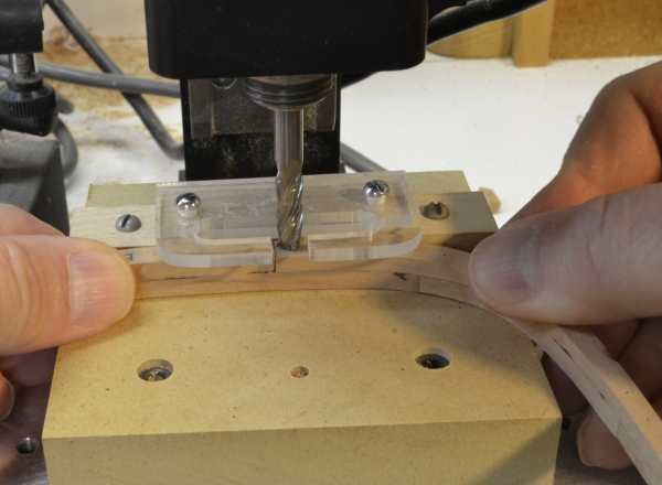
Young America - extreme clipper 1853 Part 13 –Frame Assembly 2 American Clipper Note: In 1848 there were 9 sailings recorded from New York to San Francisco and they averaged over 150 days. The following year, 1849, after the gold discovery, there were 37 passages averaging 177 days – for those that made it. From 1850 to 1853 - as the extreme clippers came off the slips - there were around 375 voyages averaging 128 days. In her maiden voyage Young America did it in the excellent time of 110 days. This was longer than the record of 89 days, 21 hours set by McKay’s Flying Cloud in 1851, but up to the end of 1853, times of under 110 days were achieved only 41 times in the 375 passages. The first picture shows frame pair A with the pins removed after assembly. The was the first pair forward of the deaflat, so there is virtually no bevel. The next picture shows the assembly being sanded back to the aft profile on the disk sander. The inside was cleaned up using a spindle sander, but left rough. At this stage the outer profiles are accurate enough to set the frame, so the patterns can be removed. This will allow the sidings of the upper timbers to be reduced. Reducing the sidings after assembly will allow the frames to be accurately beveled based on the patterns, which would be inaccurate for the timbers with reduced siding. Also, it is much easier to assemble the timbers using pins if they are all the same thickness. The drawback is that timbers have to be reduced on the finished assembly. The safest way to do this – for you and the work - is filing by hand as shown in the next picture. The sidings step down by an inch of so at each joint moving upward, so this can be done by filing then measuring. With so many frames to do, I adopted two other methods to speed the process. The first is shown in the next picture. In this method a ¼-inch end mill is lowered down to touch the piece. The piece is then removed and the cutter lowered to make the cut above the joint. Do not even think of doing this without the guard and without being able to hold the piece on two sides as shown. Although the amount to be removed at each level is small, I did this in stages of about .005”. The next picture shows how the remaining ends were done after the above step using the disk sander. Both these last methods require a lot of care. After a few frames, I decided to install the top timbers – cut from thinner 10” stock - on the forward frames after all this work. These will be visible inside the hull planking above the main deck, so this way they will all be the same size. The next picture shows a top timber. In this picture the iron bolts have been installed. The next picture shows that work in progress. As on Naiad, I used black monofilament for these iron bolts, held in with CA glue. The last picture shows the final midship frame, ready to be erected. Ed


- 3,618 replies
-
- 20
-
-
- young america
- clipper
- (and 1 more)
-
Thank you, all, for these comments. Daniel, the holes will later receive iron bolts. There were three to four 1" bolts per futtock, driven and probably riveted, flush, as you will later see. The drill diameter is the size of the pins, so there is a sliding fit. The pins are larger than 1" because I needed the stiffness in the drill to assure verical holes. The holes are marked precisely on each piece to assure alignment. This is done by placing both the pattern frames in position on the CAD template, adding the bolt holes, then copying each frame, one at a time - with the set of holes - to the pattern sheet for each. This alignment device will be more critical as the frame bevels increase fore and aft. The finished frame assembly also has patterns on both sides for bevelling. When the frame overlap is no longer wide enough for bolts, the cant frames begin. I am now working on the method for machining the futtocks to the right sidings. This gets progressively smaller above the floor. Stay tuned. Ed
- 3,618 replies
-
- 2
-
-
- young america
- clipper
- (and 1 more)