HOLIDAY DONATION DRIVE - SUPPORT MSW - DO YOUR PART TO KEEP THIS GREAT FORUM GOING! (Only 13 donations so far - C'mon guys!)
×


EdT
-
Posts
2,213 -
Joined
-
Last visited
Content Type
Profiles
Forums
Gallery
Events
Everything posted by EdT
-
Hello, everyone. I have replaced all of the lost images on pages 21 to 25 - Parts 29 to 38. Ed
-
Thank you, Peter. I wll check to see if hereis a problem with he pictures. Ed
-
Thank you, Daniel and Richard. Richard, the sooner the better. I use Titebond II PVA glue. I usually do it right after clamping or pinning and most of it washes off easily at that point. You can wait longer but then you need to brush harder to get it off. Still, glue darkened with pigmnet sometimes leaves a sort of stain that can usually be removed with light sanding. I use clean water with a stiff small bristle brush or a toothpick or cotton swabs. Excess water can be tamped with a paper towel. Wetting the wood has another benefit. It raises the grain so when sanded the finish is smoother and it you use water-based finishes, no further grain will be raised by them. This helps when using water stains, dies, inks, or thinned acrylic paints. Ed
-
Thank you both for these comments - and thank you everyone for the "likes." I hope the explanations in the last part were not too confusing. Getting all the various parts sorted out around the view ports has left me a bit confused at times. It will be clearer as we proceed - I hope. I can just discern the end of the tunnel in the strapping work - I'm looking forward to that milestone. Ed
-
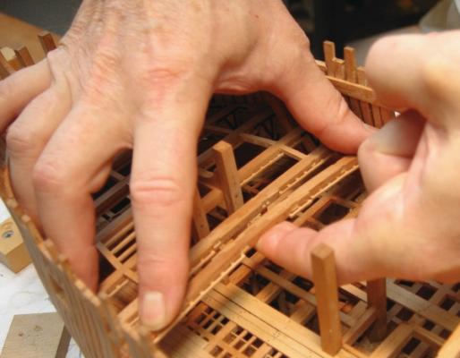
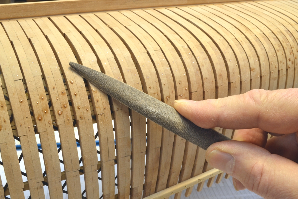
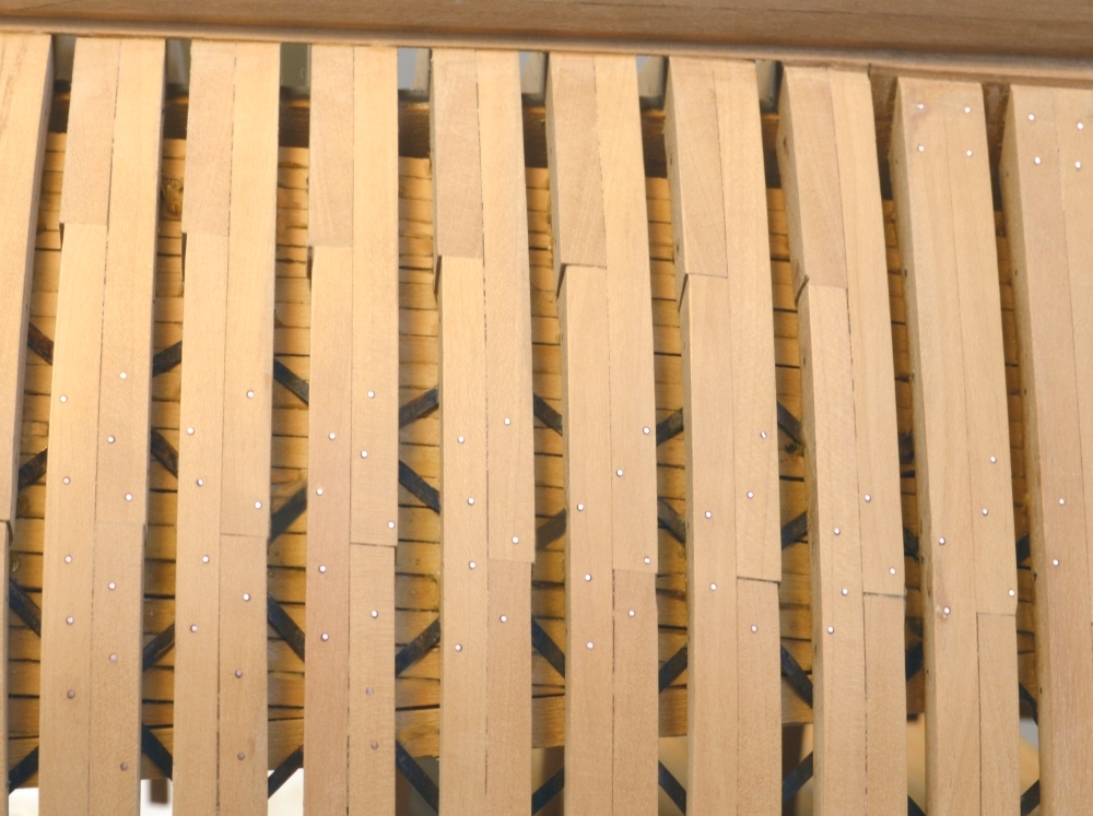
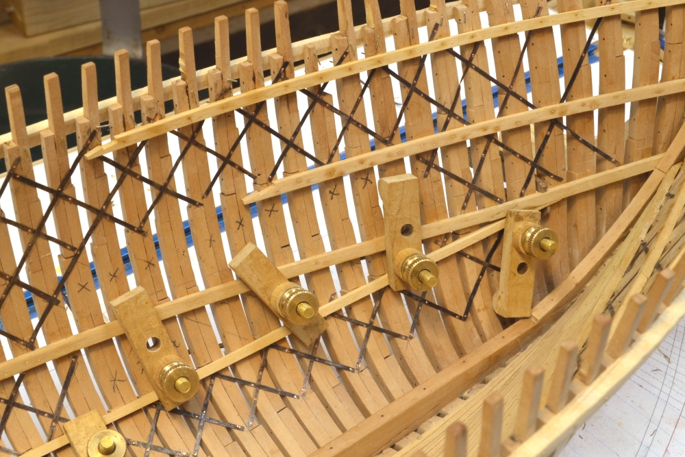
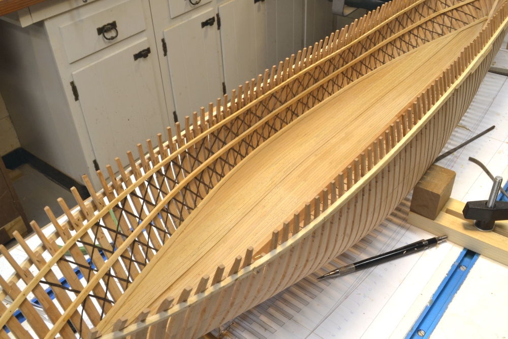
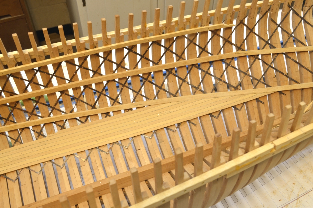
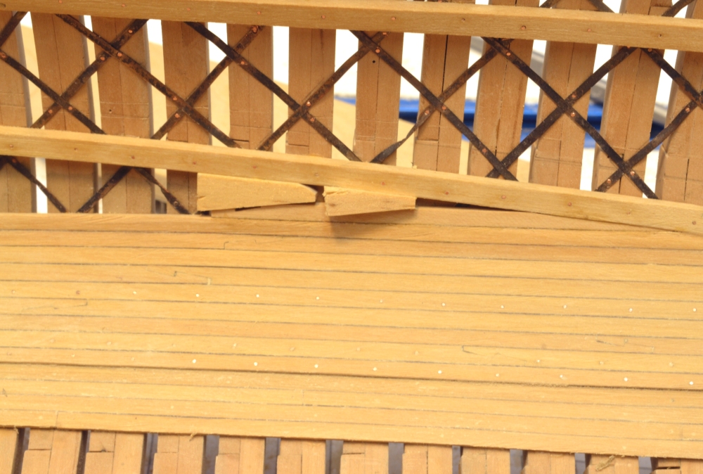
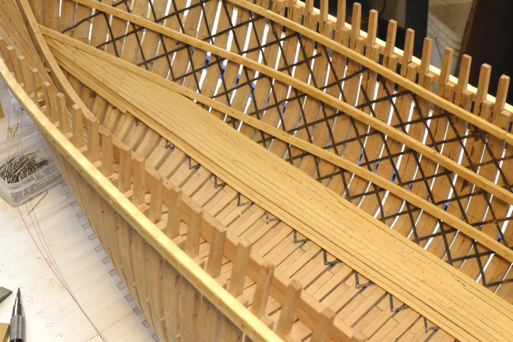
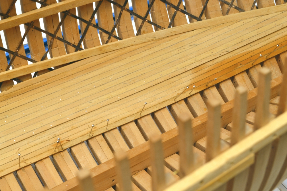
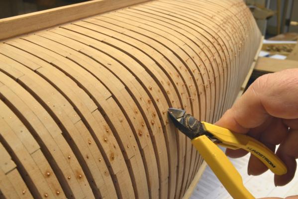
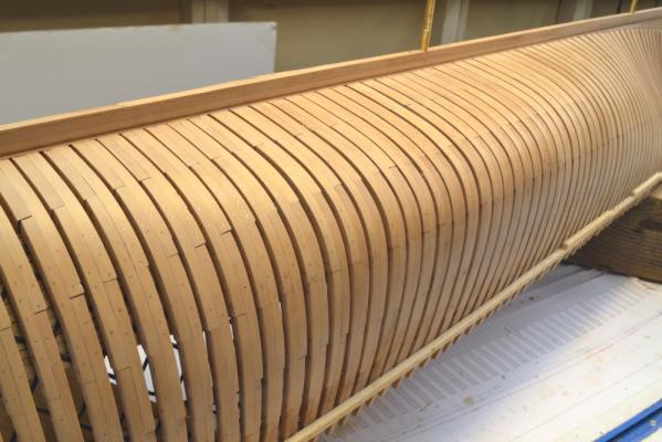
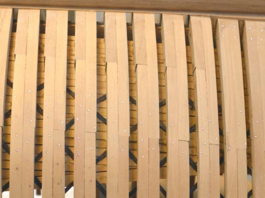
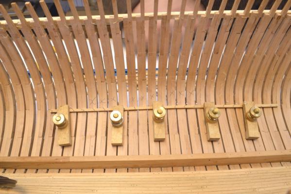
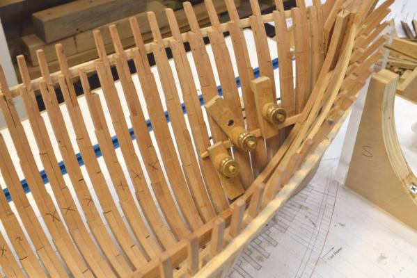
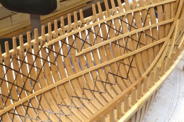
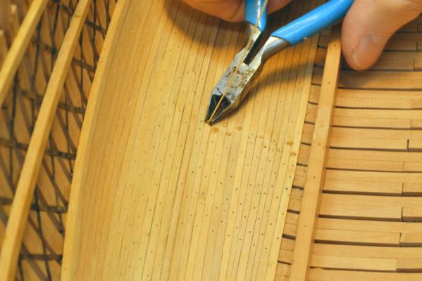
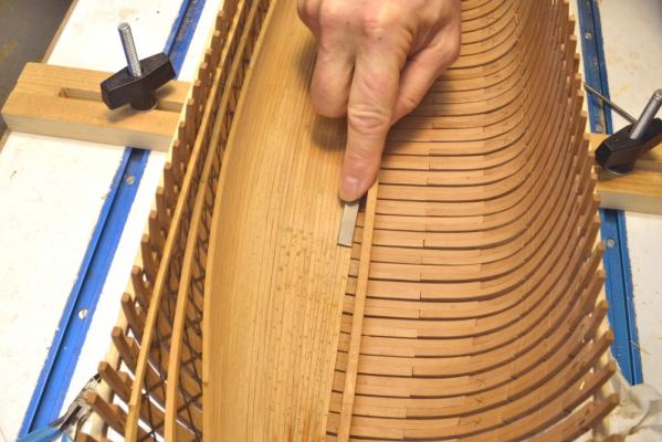
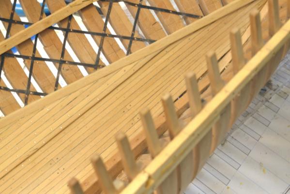
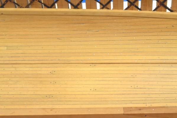
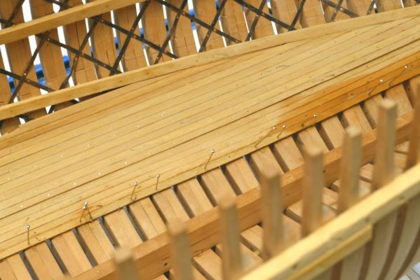
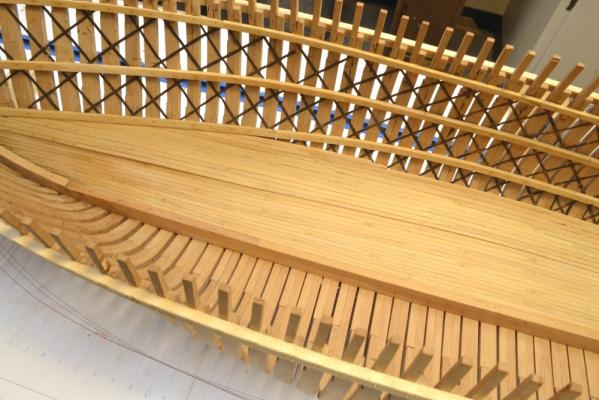
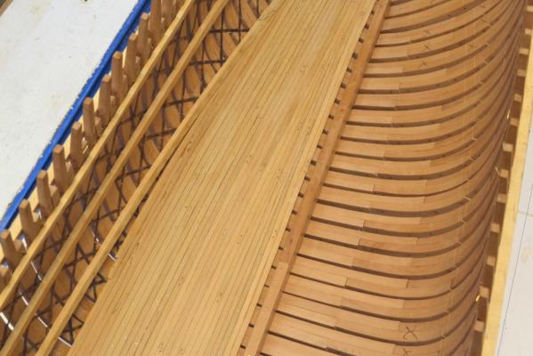
Young America - extreme clipper 1853 Part 49 – Hull cleanup, Port side ceiling Before moving to the interior of the port side, I wanted to remove the protruding bilge ceiling bolts on the starboard side of the hull. There will be many more of these to be added but the installed wires are a hazard. The first picture shows the epoxied through-bolts being clipped off. The remaining bolt stubs and epoxy were then filed off as shown below. A fine cut file works best for this because it doesn’t “grab” on the wire. The next picture shows the lower hull sanded after removal of the bolt heads. The next picture is a close up showing how the iron strapping will appear between the frames. Most of the strapping on the inside will be covered with planking. The copper wire bolts are bright in this picture and will be blackened later, just before applying finish to the hull. The next picture shows the start of work on the port side with the installation of the first strip of bilge ceiling near midship. This first strip is installed just below the heads of the first futtocks. This sets the line of the bilge ceiling that the other strakes will follow. There are four more thick strakes below this. Above it, thick members extend up to the lower deck clamp as on the starboard side. It may seem odd to install this before the strapping, but I did it for two reasons. First, I wanted a very secure joint with the frames, especially on this side where a number of frames will be removed above this joint and below the middle deck clamp – to provide view ports into the hull. Secondly, the pins shown in this picture were used to correct any irregular spacing between the frames. This had to be done before strapping. After gluing and before removing the clamps, most of these pins were replaced by copper bolts. The next picture shows the first section of lower deck clamp being installed. In this picture and the one that follows, the frames marked “X” will be cut out between the lower futtock heads and the middle deck clamp to provide the view ports. The next picture shows the strapping covering all but the forward view port area. There will be three of these view ports, one at each mast. Sections of the deck clamps have also been added. The lower deck clamp is not glued or bolted to the “X” frames, but the frames are securely bolted to the clamps above. Note from the “X’s” that there are three groups of three frames to be cut out. This will be done much later when the structure has been well reinforced by additional members. The last picture shows the strake of bilge ceiling extended forward along the lower futtock heads to intersect with the lower deck clamp. All of these members are being epoxy bolted through the frames as they are installed to provide the primary strength to the joints with the frames. Glue alone is not enough, especially where there is strapping. Ed


- 3,618 replies
-
- 25
-

-
- young america
- clipper
- (and 1 more)
-
Sorry, ric. I don't understand your last question. You are on the only Young America log I have. Ed
-
ricskinner, I was not aware there were any kits for this ship and am not familiar with the kit you describe. I'm afraid I cannot offer anything in the way of further information for building this kit. There are an excellent set of drawings by William Crothers available from Loyalhana Shipyard at a scale of 1:96 if you are looking for more information about the ship itself. There is also Crothers book, The American-Built Clipper Ship. Ed
-
Thanks for the nice comments and for the 22 "likes"! I should be posting pictures of the latest work within the next few days. Ed
-
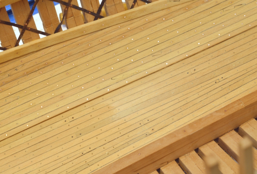
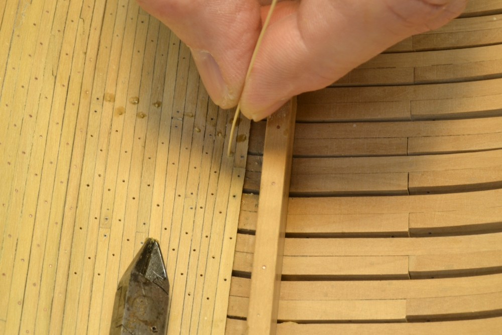
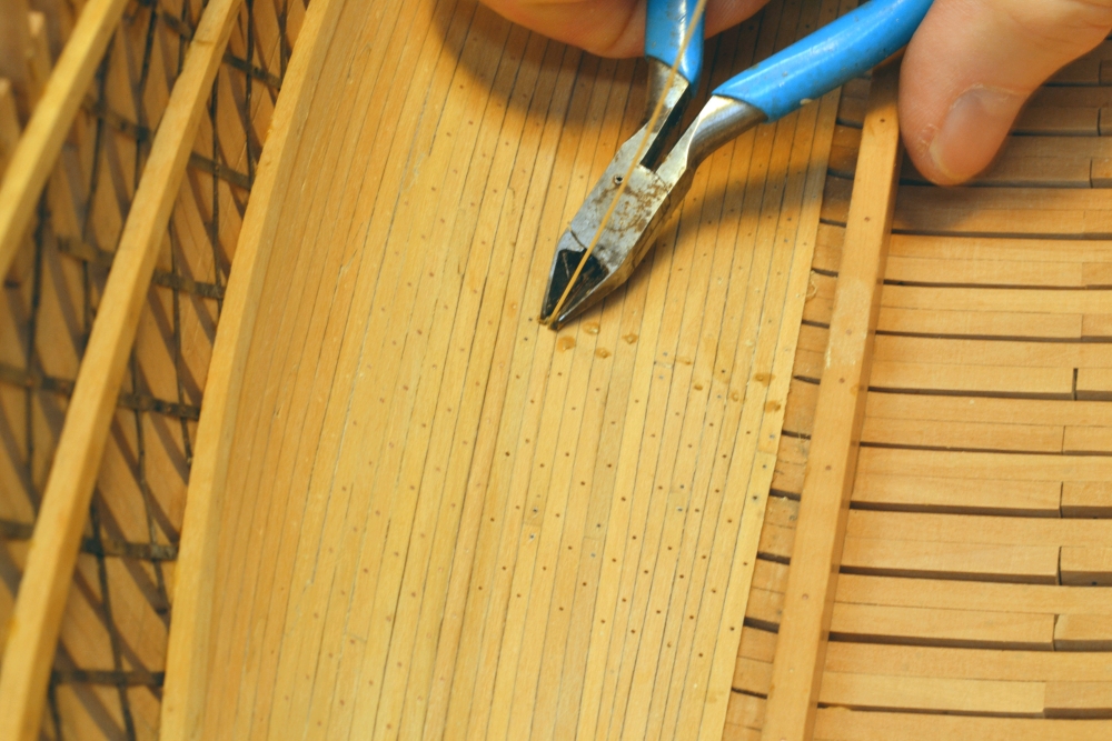
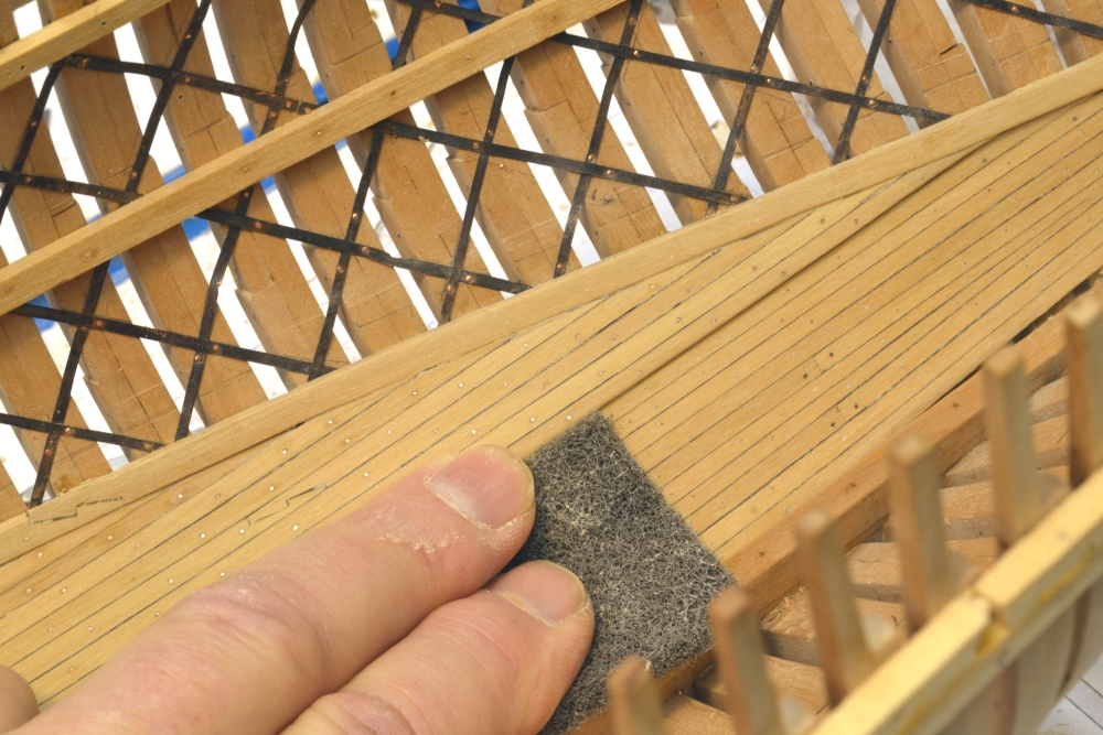
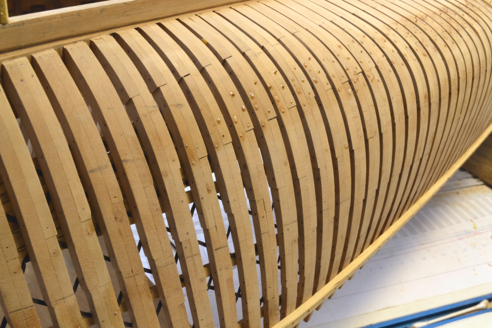
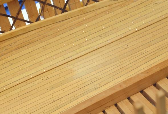
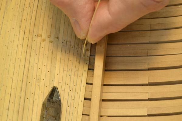
Young America - extreme clipper 1853 Part 48 – Starboard Ceiling Treenailing and Bolting In the first picture, the floor ceiling planking is installed except for Treenailing. The thicker bilge ceiling above it has been completed up to the underside of the lower deck clamp, except for the bolting. While the last few strakes of bilge ceiling were being installed both the bolting and treenailing was begun. The next picture shows some of these fasteners installed. The copper wire bolts in the thicker ceiling show as bright dots in this picture. They were iron bolts driven through each frame and riveted flush inside and out. Before finish is applied these will be blackened. This section of floor planking below the thicker strakes has been treenailed and some sanding has begun. The butt ends of these planks were secured with iron blunts, represented here by black monofilament CA glued in. All of the tree nailing was completed in three sessions that included making the treenail strips from bamboo skewers. In the next picture one of these .020” strips has been dipped in glue and is being inserted into a predrilled hole. The holes are just large enough for a slip fit. After pressing to the bottom of the hole using the clippers, the strip is cut off as shown below, the new end is sharpened with a razor blade and the process is repeated a few hundred times. The excess glue is washed off with clean water. When dry the nail heads are filed off flush as shown below. The planking was then sanded with 120-grit followed by 220-grit paper and then buffed with Scotchbrite as shown below. The next picture shows the area at the stern after these steps. The next picture shows a section of the ceiling after all of the treenailing was installed and the planking sanded and buffed. The wire bolting of the thicker strakes is only partially complete on the right side of this picture. The treenails are not too pronounced in this picture, but they will “pop out” and be more visible when finish is applied later. The iron bolts at the butts are quite visible here. The copper bolts into the top of the keelson at the lower margin of the picture were copper and will not be blacked. All of the ceiling work on the starboard side is now complete. The next step will be to sand down the bolts on the outside of the frames and then move on to the ceiling on the port side. Ed


- 3,618 replies
-
- 35
-
-
- young america
- clipper
- (and 1 more)
-
Thank you all for your comments and "likes". Jim, I really appreciate your vote of confidence and Greg's comment as well. After I decided to maximize the modelling of fasteners, particularly structural bolts, on Naiad, I struggled a lot trying to turn the chaos of bolt placement into some semblance of orderly appearance - in vain I am afraid. So, I needed to come to terms with the appearance - and I have - with no regrets. I am probably overly sensitive to what some may make of the appearance - but I must say, there have been no negative comments to date. Again, thanks. Ed
-
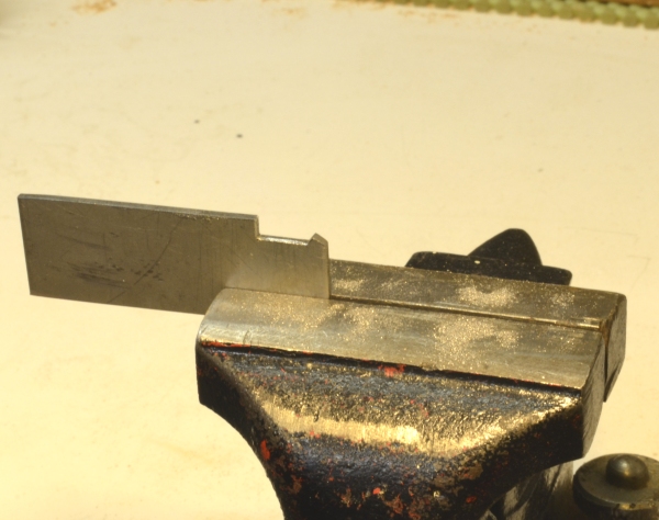
Christian, I agree with druxey that it is easiest to cut the keel rabbet before framing. The floor timbers will interfere with the v-gouge. However, I believe the rabbet can be successfully formed after framing with a scraper like the one below. On Young America there is no hogg on the keel so forming the complete rabbet leaves very fragile feathered edges on the upper corners. I was afraid these would be damaged in later construction, so I only partially cut the rabbet (using this tool) before framing, then went back after framing with the scraper to finish the job. The scraper rides on the bottom of the keel and needs to be made to clear the floor timbers - like the one in the picture. I believe this method could be used to form the rabbet after framing. Ed

-
Very nice work, Bugra. Simple tools are often the best - as you have shown. Ed
-
Thank you, Greg. Nice to hear. Ed
-
Scoot, Sorry I missed your question. The answer is yes. Ed
-
David, Modelling of fasteners is an interesting topic. I agree that modeling decisions rest with the individual. If this were not so, I wuld be doing something else. I am afraid my approach to fasteners may be outside of the mainstream in that symmetry and aesthetics in model fasteners are not primary drivers for me. These ships were densely peppered with fasteners of different types in apparently random patterns. They would not make award winning models. Choices must be made. Since my main area of interest is in structures, I personally lean toward authenticity in fasteners - not that this can be fully achieved. I accept that the random effect will be criticized. Its a personal taste. YA's ceiling treenails are .020" bamboo - scale 1 1/2" at 1:72. The 1" iron bolts and blunts made from copper wire or monfilament are about the same size. Some bolts were/are larger. Since they are generally riveted, the ends would be larger at the surface. As an example of bolt density, if I remember correctly there were 18 1" bols in each hanging knee. I do not forsee being able to install all of those and generally install fewer than the full authentic number. I hope this helps explain what I am doing. Ed
-
Thanks, everyone, for the comments and "likes" - and thanks for the thoughts about treenailing and my mental state. The tedium of treenailing his highly overrated. Two sessions in the last two days and it is 3/4 done - as is the copper bolting of the bilge ceiling - and all those members are now intalled. Pics in a day or two, when he starboard ceiling work will be complete. Ed
- 3,618 replies
-
- 2
-
-
- young america
- clipper
- (and 1 more)
-
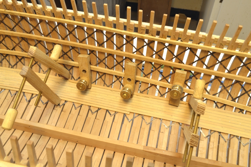
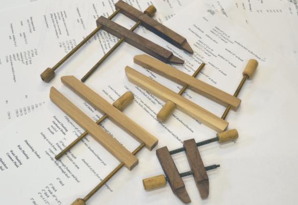
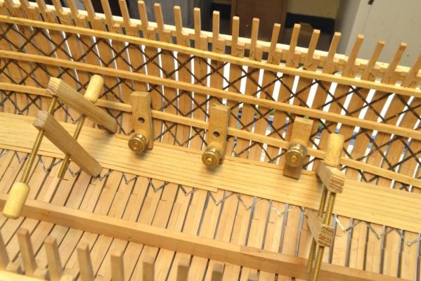
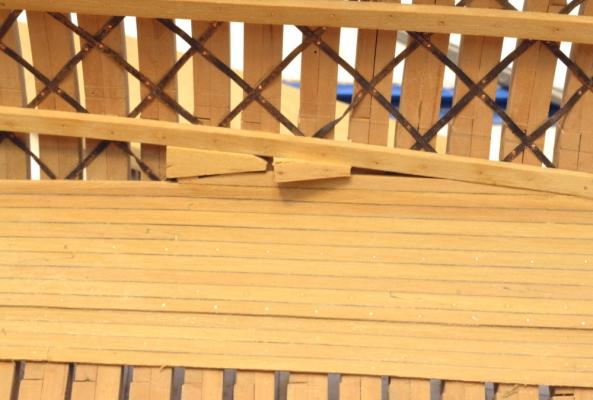
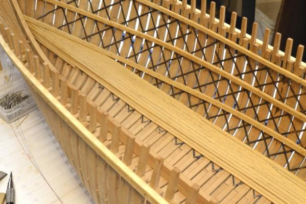
Young America - extreme clipper 1853 Part 47 – Bilge and Floor Ceiling The first picture shows the 8” thick bilge ceiling being extended up the underside of the lower deck clamp. The clamp would have been edge bolted down into these thick members. With the clamps and frames they formed a sort of girder over the length of the hull to combat hogging. I mentioned earlier that these 8” x 8” bilge ceiling members required some serious clamping to close their joints. The next picture shows some remodeled clamps used to assist in this work. In these clamps the old jaws were replaced with stronger versions. I used the strongest wood I could find in my old scraps collection. The dark colored jaws are black walnut and the lighter ones hickory from and old axe handle. The walnut clamps had the ends of their jaws narrowed down to fit between the frames from the outside. The next picture shows a pair of these being used to close up a joint. Up near the deck clamp, soft pine wedges could be used to close the joints as shown in the next picture. The next picture shows the hull inverted so the epoxy bolts on the outside could be sanded off – to help save my hands when working from the outside. There are many more of these bolts to add as the bilge ceiling progresses. The next picture shows the first few strakes of 4” thick floor ceiling installed. The contortions from the convex to the concave hull shape made this interesting at the ends. All of this 4” and 8” thick ceiling was of hard pine, so I am using Castello for it. Pear is being used for all oak. The next picture shows a strake being installed using .021" pleating pins in tight drilled holes to hold it in place when glued. The dark area is wet from washing off glue from between the strakes. One edge of these planks is coated with dark brown latex paint (before ripping) and dark glue has been used on that face. Plain yellow glue was used on the frames and washed off from the outside between the frames with a wet toothbrush. In the next picture the floor ceiling has been completed down to the limber channel. Several stealers had to be installed so the final strake would be parallel to the keelson. The next picture shows the limber channel. When this picture was taken, the planking had been leveled out with rifflers and some sanding. Bolts were then installed at the ends of each plank. Each plank will next be treenailed at every frame. Can’t wait. Ed


- 3,618 replies
-
- 29
-
-
- young america
- clipper
- (and 1 more)
-
Impechable, Micheal. Love the bearings. What is the wood? Looks like fir? or Spruce? Ed
-
Sailor, Olivier's report says a jack was used in the center of the beam. With that in mind, my guess is that the bean was laid out at an angle with the center at the final line and a screw jack up from the beam below - or off the pillar - placed at that point under the beam. The ends could then be held down with tackles to the beam below. As the beam was sprung with the jack and shortened, it could be rotated into position and the tackles eased to let the beam fit into place. Anyway, that is how I would do it. The beams do not have to be sprung very much. A 30' beam 14" wide would be about 0.3" too long measured between the diagonal corners. A fifteen foot beam of the same width would be about 5/8" too long. The sloping sides would require additional springing depending how high the beam was held above the clamp when rigged into place. Ed
-
Thanks, Guys. Daniel, I cut a 45 deg triangle out of flexible card, laid one edge along the leelson and used it to mark the lines. I believe it was Seppings who promoted the use of doagonal bracing in HM hulls. Ed
- 3,618 replies
-
- 1
-
-
- young america
- clipper
- (and 1 more)
-
ROYAL CAROLINE 1749 by Doris - 1:40 - CARD
EdT replied to DORIS's topic in - Build logs for subjects built 1501 - 1750
Brilliant, Doris. Ed- 883 replies
-
- 1
-
-
- royal caroline
- ship of the line
- (and 1 more)
-
Sorry guys. I seem to be pushing on a string. My suggestions - perhaps not expressed well - relate more to the lofting than to the way or when the wood frame is actually bevelled. Frame patterns need to provide sufficient material (usually on the inside of the smaller profile) so the frame can be bevelled without thinning the smaller face. There are various methods to do this, but it needs to be done. Sorry if this point was obscured in my comments. Ed
-
Nils, Let me add my thanks to you for posting the beautiful pictures of the very excellent build. Ed
-
Toni, The original shipwrights had the same problem fitting beams into place - even without the knees. Their end clearances were very close and the frames above the decks "tumbled home." I suggest you do what they did if you can - spring the beam by lifting the center while holding the ends down, then rotate it into place. I installed Naiad's beams with knees attached using this method. Thanks to Blaise Olivier's 1737 commentary on English practice. (The French at the time apparently set the beams then raised the clamps under them.) Here's a picture. Ed