EdT
-
Posts
2,214 -
Joined
-
Last visited
Content Type
Profiles
Forums
Gallery
Events
Everything posted by EdT
-
Gary, I appreciate your purchase of the books and your plan to build a Naiad model. I am also flattered that you would want to maintain a “pristine” copy of the material. I have given some thought to your request, and since others may have similar desires, I would like to answer with some explanation. Like many who contribute to MSW, I have a pretty strong interest in freely supporting the craft of model shipbuilding and ship modelers. I hope this is evident from my other postings on this site and especially in the authorship of the two Naiad books. Books of this type that serve a very small market are very far from being profit-making propositions. Books like Naiad, Euryalus and others, that include drawings and other media attachments are expensive to create and produce. They cannot be priced based on their true cost. Publication would not be possible without authors working essentially for free – plus bearing the costs of producing the materials – cameras, software, computer supplies and the like. I am sure you know that many books, including some mass market books, do not include drawings and some sell these separately – at prices well above the cost of books. For these reasons, Seawatch books like Naiad, if I may say so, are an extraordinary bargain. They will, in fact, turn out to be a minor cost in the overall model project. Given all this, I do not feel it is appropriate for me to provide release to any copyright restrictions. I would hope that copy services and fellow modelers that purchase these and other books would appreciate and honor the copyrights. It seems a small thing to ask. I would be remiss if I were not to acknowledge the contribution of Seawatch books in this note. The service these books provide to model shipbuilding is enormous and involves substantial commitment and work. For the reasons cited above the financial gains are small. Bob and Cathy deserve our thanks and support. This does not solve your problem. I can offer some suggestions. One option is to put the cost of copying drawings toward purchase of a second book. I know of modelers who have purchased second books to retain as “library” copies, using a separate copy in the workshop. This is one option. Another less expensive approach is to provide for drawing protection in the workshop. I found that attaching drawings to plywood sheets that hang from the wall allow easy taking of measurements and minimum damage to the drawings. If you wish to use drawings on the workbench, as I often do, I would suggest covering them with a sheet of thin clear plastic. Also, you willl note that drawing 2B, which is virtually identical to Drawing 2, was an extra provided as a base board drawing to preserve drawing 2. Others may offer good suggestions as well. Thank you again for your interest in Naiad and the books. Ed
-
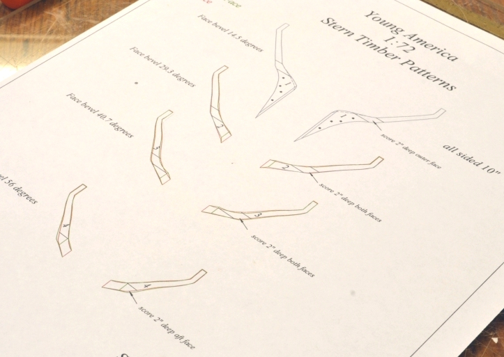
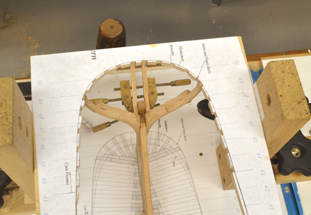
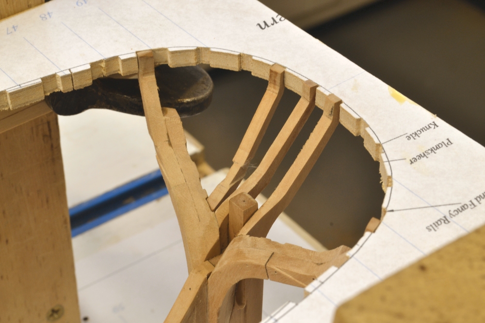
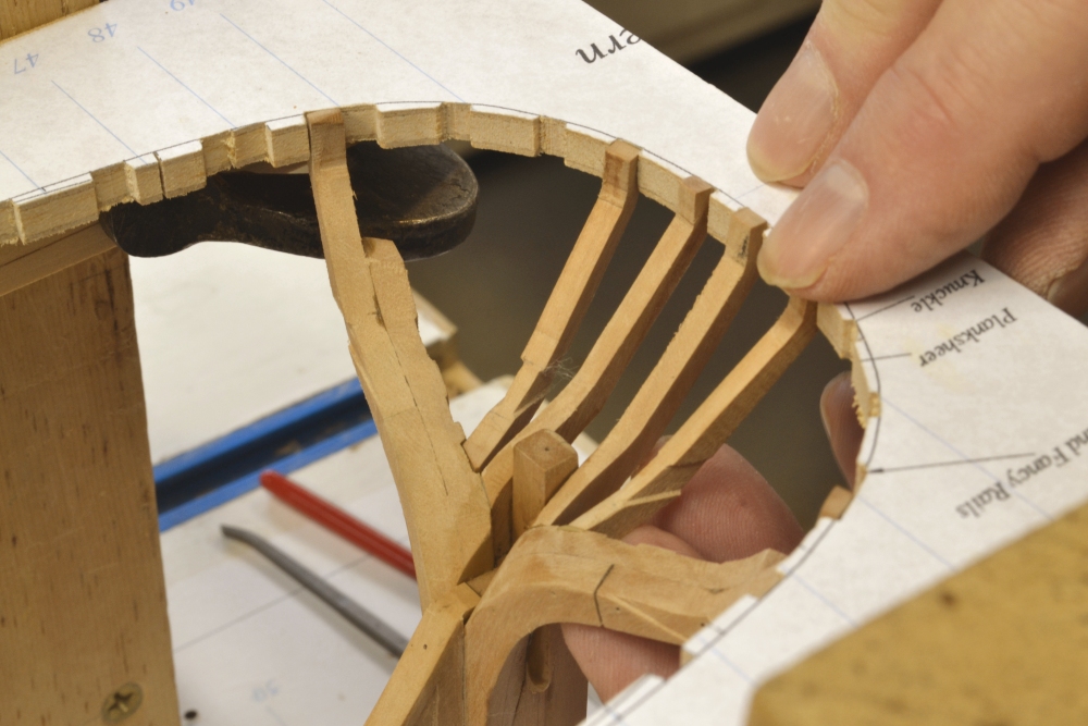
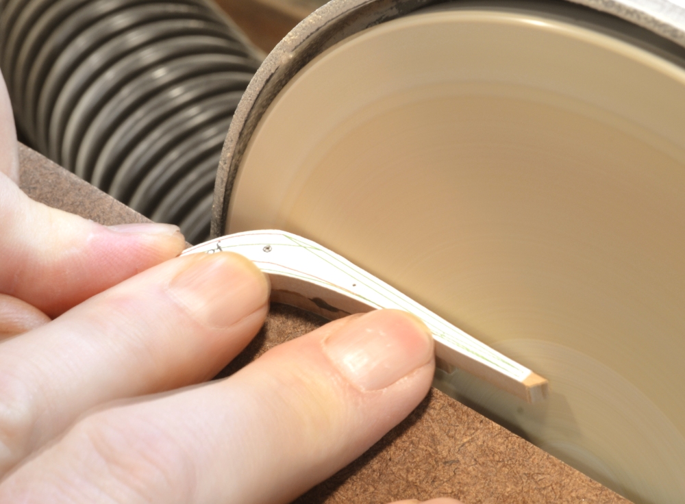
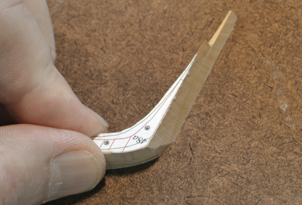
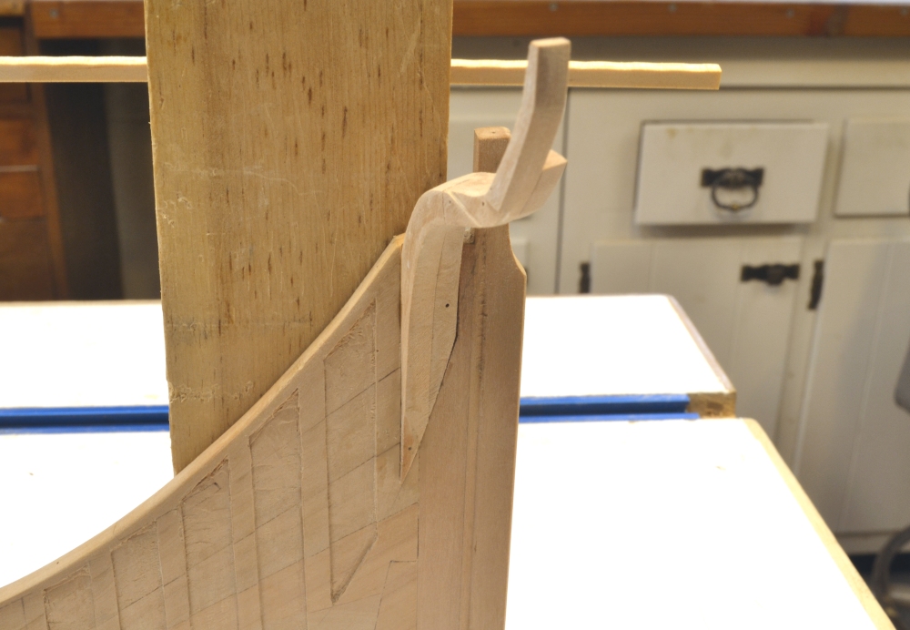
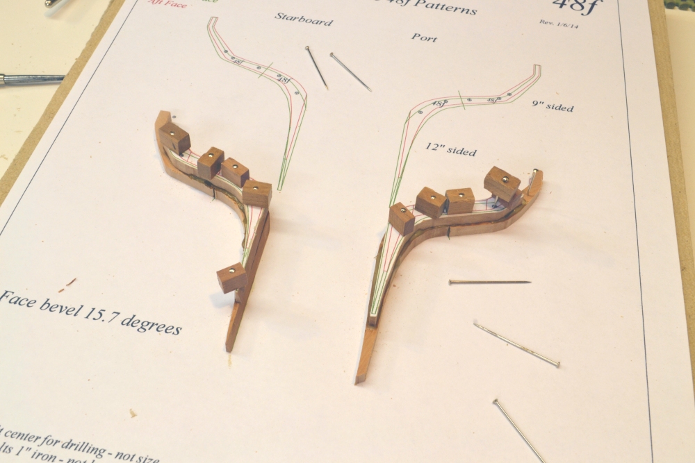
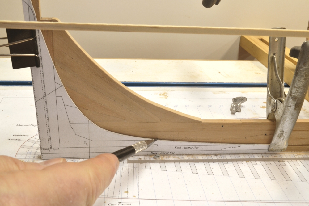
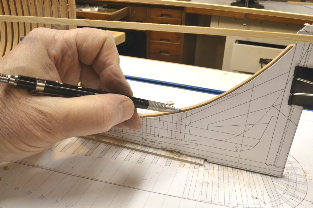
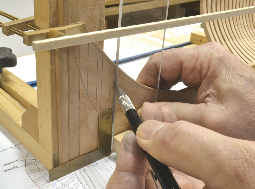
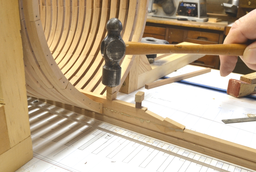
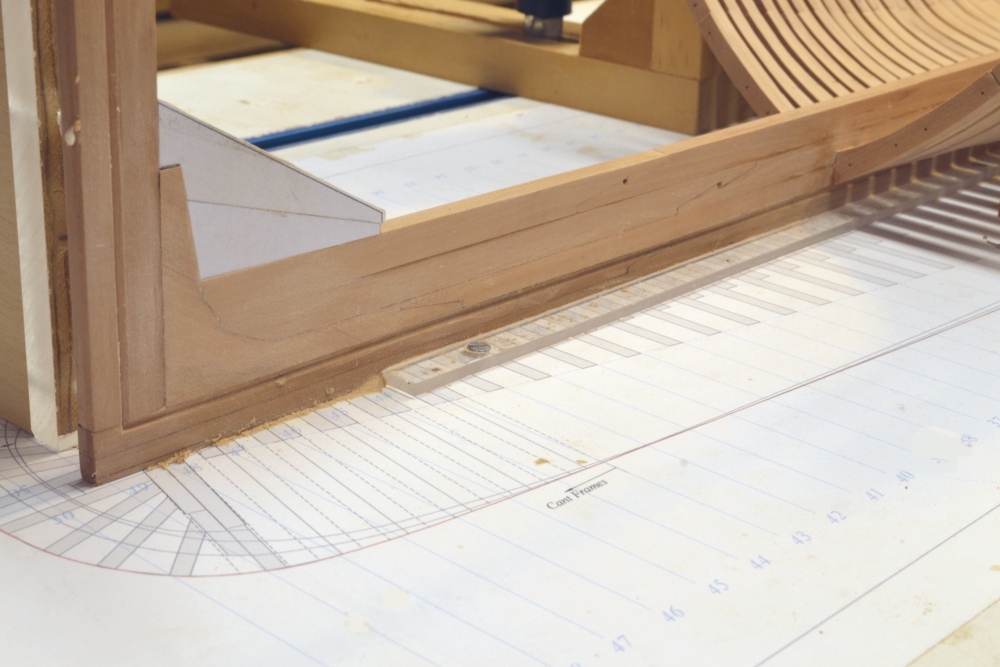
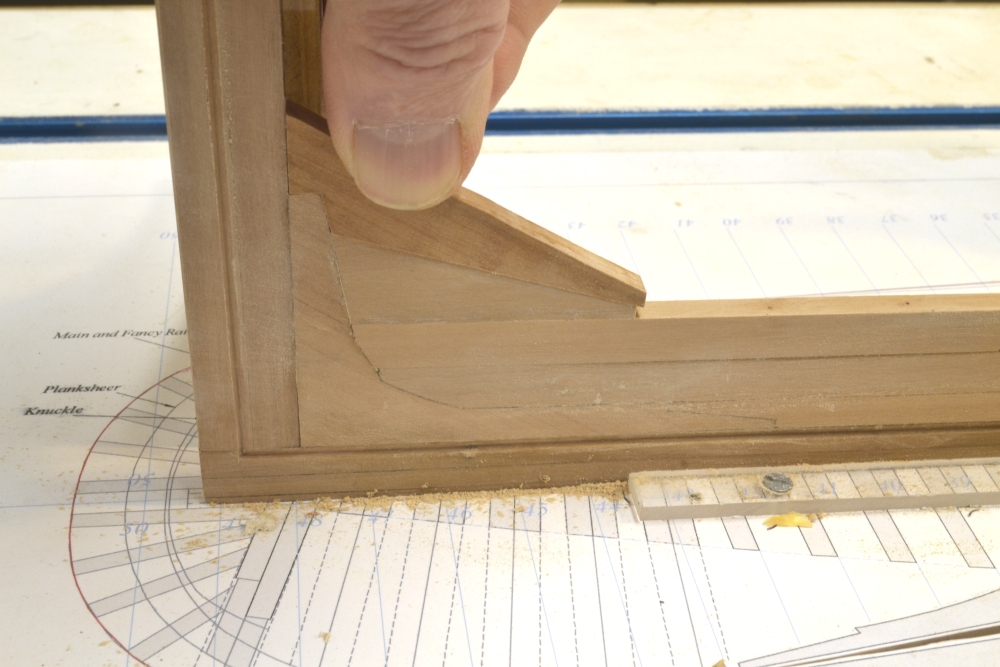
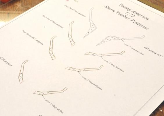
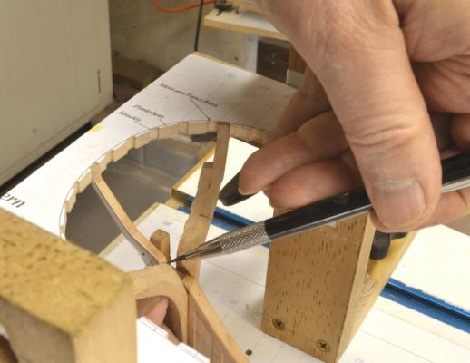
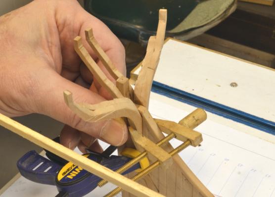
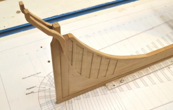
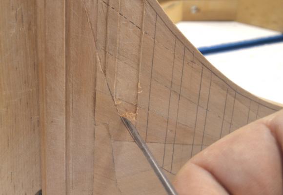
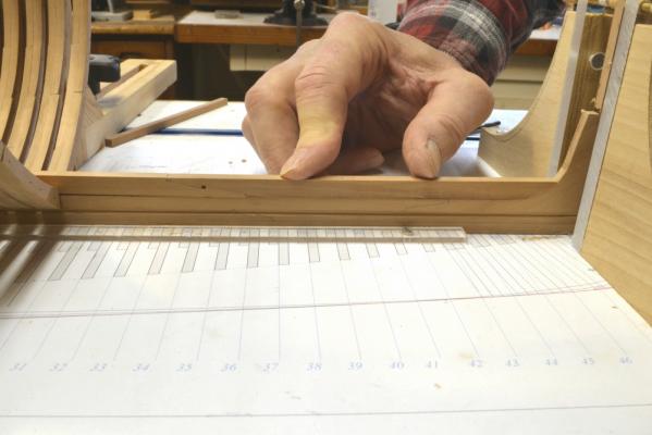
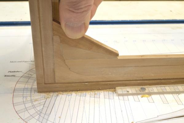
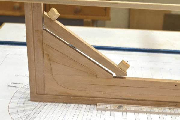
Young America - extreme clipper 1853 Part 37 – Stern Timbering 1 I have been looking forward to the stern timbering for some time – in fact since first deciding on the subject ship. At first glance it looks a bit daunting, but the plan view template and accurately lofted patterns turned the assembly into a pretty easy task. Most of the work was in the lofting, so I included a picture of the pattern sheet for the eight timbers. The pattern lofting was a bit complex. The timbers are angled off of the last cant frame, which is itself at an angle. Some mental gymnastics were needed to find enough points on the drawings to plot the four curves for each timber. I did one for a trial and its fit encouraged me to go on and add the scores for the horizontal chocks to the patterns. Those chocks will be added in Part 38. In the next picture a new version of one of the central timbers shown earlier is set temporarily in place and the bevel against the aft cant frame is being marked. The pattern is still on at this stage. In the next picture, after installing the one shown above, its opposite counterpart is being glued on. These were made before I decided to loft the scores on the patterns so these will be cut later, in place. The two timbers will later be bolted through the sternpost. In the above picture, the vertical scores for the stern timbers can be seen on the cant frames. The next picture was taken at this stage but from above. In the next picture, the first of the angled timbers has been fit into place. Note the horizontal scores for the filling chocks at the knuckle. In the next picture its opposite counterpart is being fit. The joint face angles for all these were measured from the plan drawing, printed on the pattern sheet and faced off on the disk sander with the table set at an angle. Only slight trimming of the sides of the scores was needed and all fit very well as can be seen in the last picture. Following this work, the template was removed to allow a final check of the heights of each timber at the top – the “fancy rail” height – before going on to the filling chocks between the timbers. Ed


- 3,618 replies
-
- 33
-

-
- young america
- clipper
- (and 1 more)
-
Thank you, all, for the comments and all the "likes" on the last post. Frank, I have both books. the content is very similar and in many cases duplicated. If your ship fits more into the packet mold, there is no need to have both. Good luck with your project. Daniel, I'm very flattered y your offer. I am afraid that you would find my workshop floor very messy. I should have the next installment posted shortly. Thanks, again, for the support. Ed
-
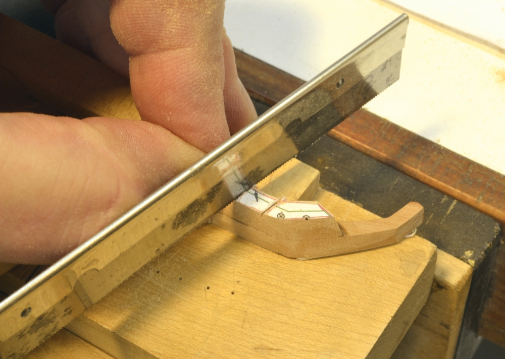
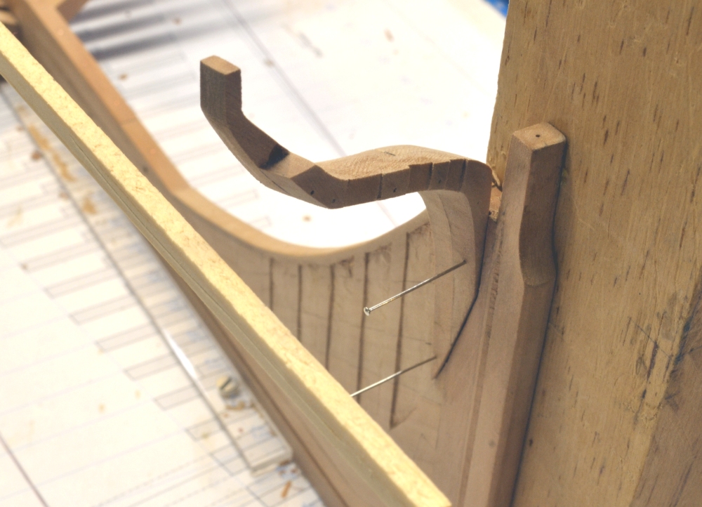
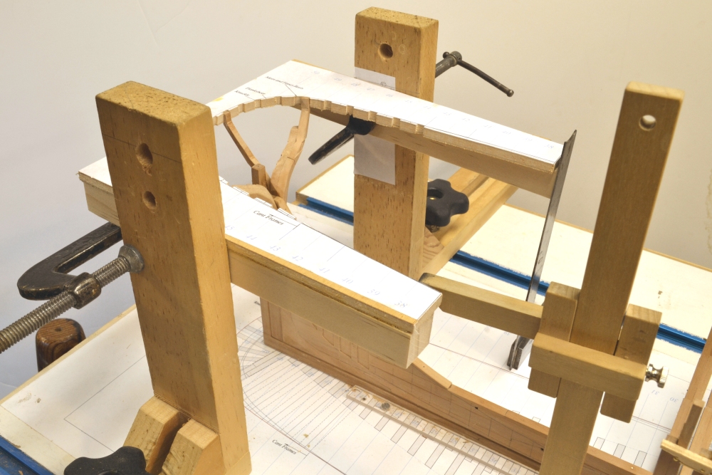
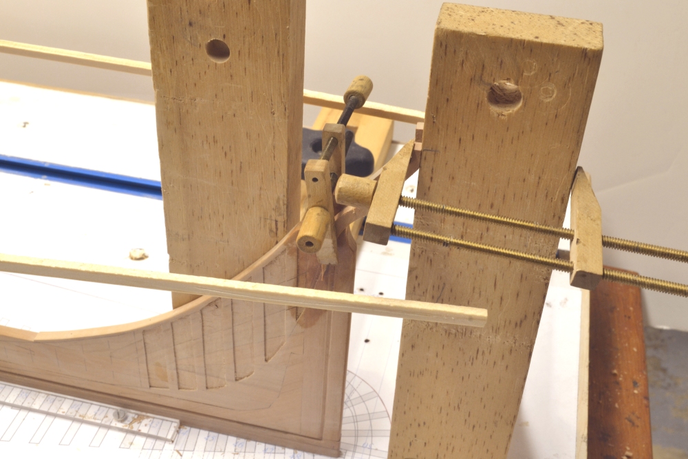
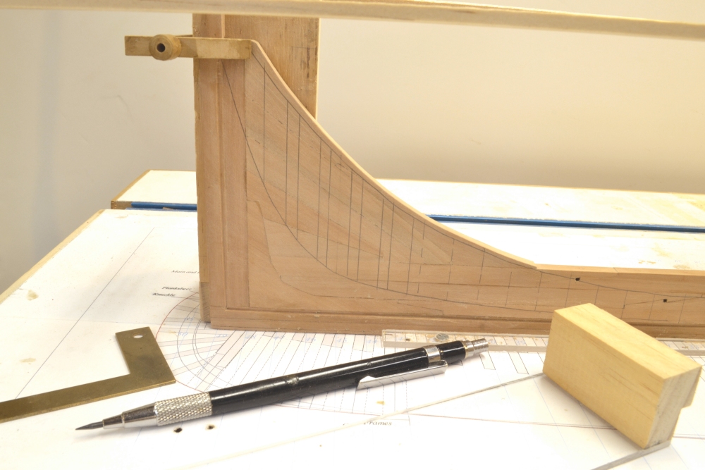
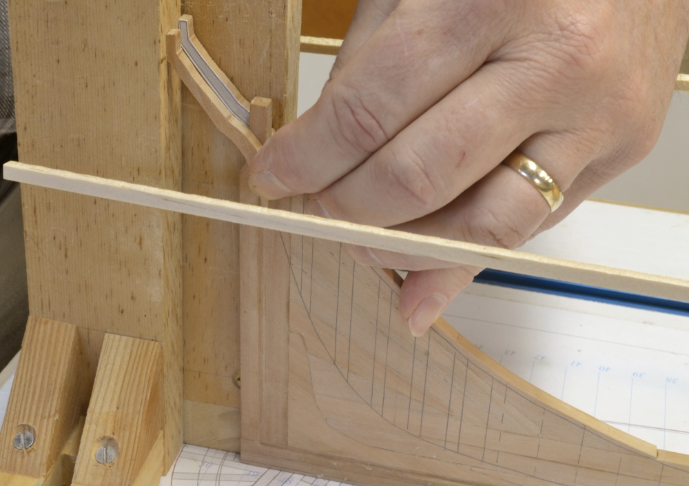
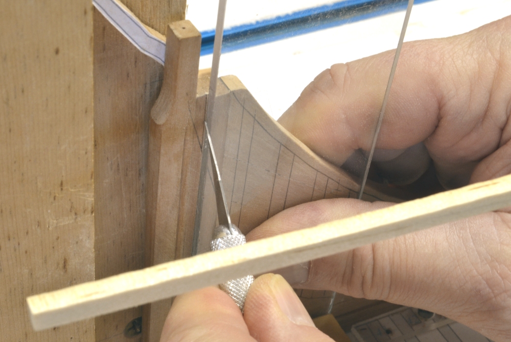
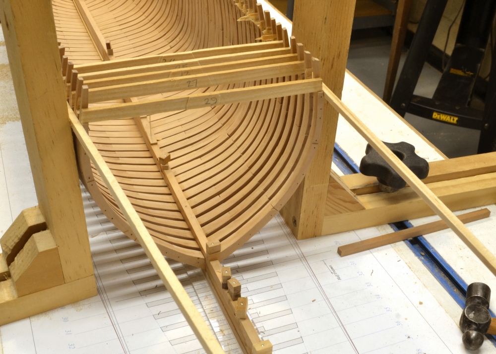
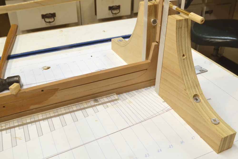
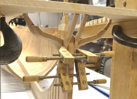
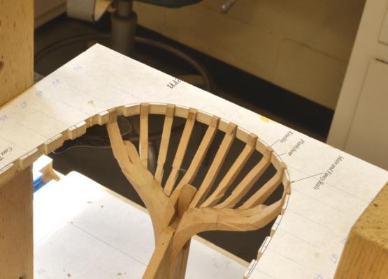
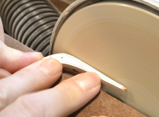
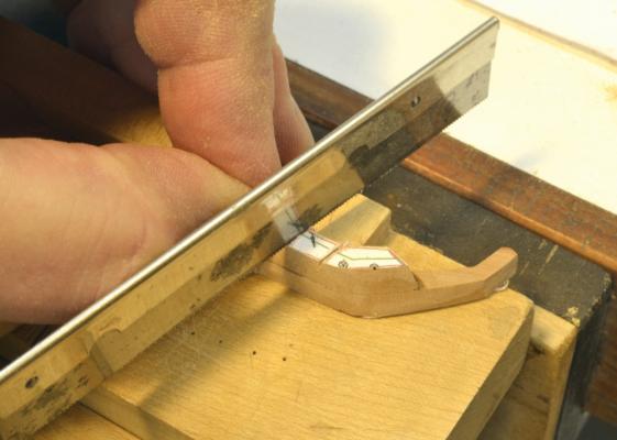
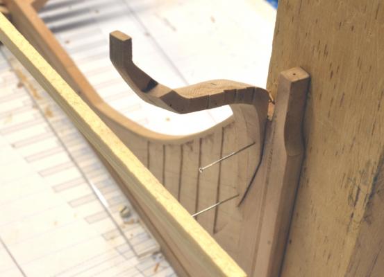
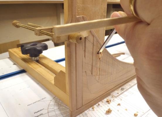
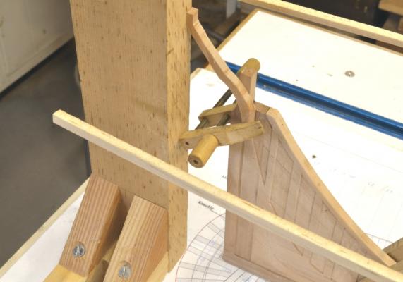
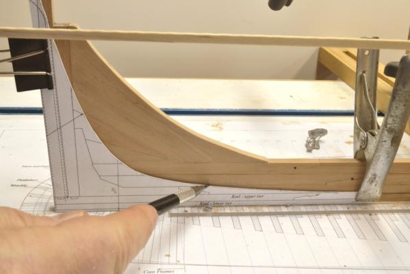
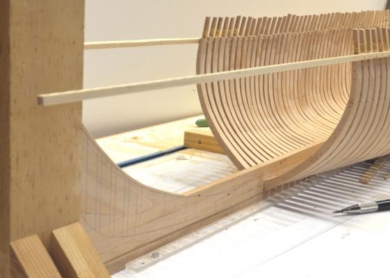
Young America - extreme clipper 1853 Part 36 – Aftermost Cant Frames (#48) The last picture in the previous posting showed the two aftermost cant frames being assembled. The same pin indexing was used as discussed in previous posts. After assembly the frames were beveled. The first picture shows the deadwood mating surface on one of the pairs being beveled using the disk sander with the table set at the correct angle. These angles are printed on each frame pattern from generated measurements on the CAD drawing. They are very accurate and the disk sander reproduces them fairly effortlessly. The next picture shows the joint bevel. This picture was taken before the outer bevels or the shape at the bearding line were shaped. The picture shows vertical lines on the pattern aft face that mark the scores for seating the three angled stern timbers that bolt to that side of this frame. In the next picture the lines scores being cut with a razor saw. There is also a horizontal score on the forward face of this frame at the “knuckle” of the of the aft hull shape that occurs roughly at the line of the wale. Horizontal chocks will be inserted in these scores between frames to support the ends of the planking below the wale at the stern. Similar chocks will be placed between the vertical timbers that shape the circular stern. This will be clearer later when those timbers get installed. The next picture shows the port frame in its initial fitting into the aft score on the deadwood – held by pins at future bolt locations. In the last part I showed a picture taken earlier with the two central stern timbers installed. After about an hour of trying to fit the cant frame neatly against one of those and into the score I decided to install the cant frames first. So the central stern timbers have been removed in these pictures. The three vertical scores on the aft face can be seen in this picture. The temporary ribband seen in this picture and its starboard counterpart were becoming increasing obstructive to all this work and were soon cut back and removed. The next picture shows the installed frame pair. The horizontal score on the forward face can be seen in this picture. The next picture shows the starboard frame clamped for gluing. The two central stern timbers are being held up in position in this picture. To assist in fitting and installing the eight stern timbers that form the curve of the circular stern, a template was made to help with this. It is shown in the next picture. The plywood template is clamped tightly to the two “clamped squares”. The height at the center of the stern and on each side at about frame 38 was set using the caliper shown in the picture. The line slopes down slightly going forward. The template was also horizontally aligned up from the base drawing using the square shown on the port side. The template is fit over the two installed cant frames. One central timber is loosely fit into its notch in the template. The next task is to loft, make and install the eight timbers that form the circular stern. Ed


- 3,618 replies
-
- 26
-
-
- young america
- clipper
- (and 1 more)
-
Outstanding, Remco. I love the realistic brick colors and the pots are magnificent. I assume you wil be putting a masonry base under it? Does the deck framing provide additional fireplace carlings and pillars to take the load? Ed
-
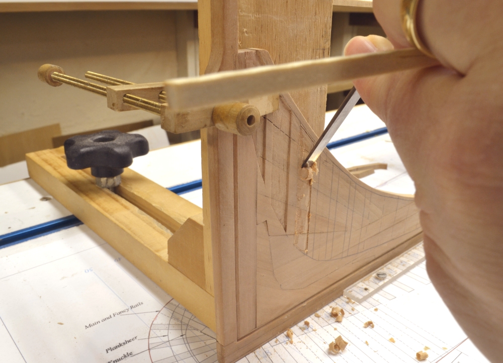
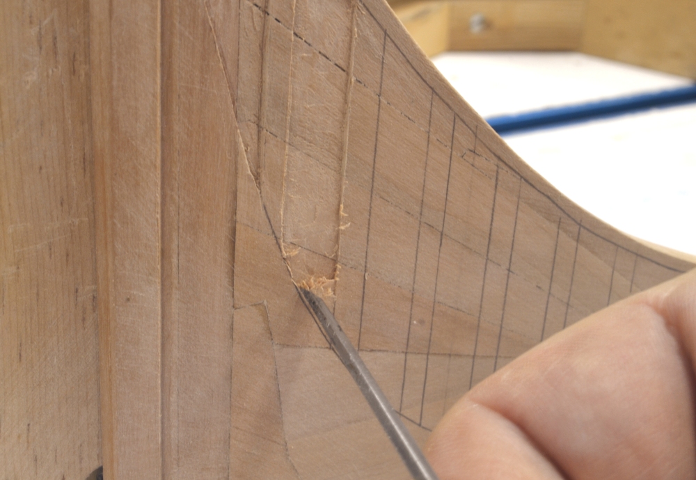
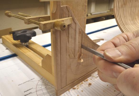
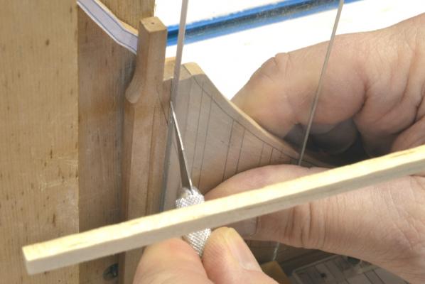
Young America - extreme clipper 1853 Part 35 –Deadwood scores continued/stern timbers Chiseling out the cant frame scores in place has gotten some comments, so I will show a couple more pictures of this. In the first picture, a ¼” wide paring chisel is being used to pare out the third score forward after the outline had been scribed fairly deeply to prevent tear out. In this picture the chisel is being used with the bevel against the work so the bevel angle can be used to keep the paring cut vertical and controlled by the angle of the chisel. The chisel is being lightly tapped with a small mallet. This permits much better control of the cut than pushing the chisel and risking slippage and tear out. In the next picture the chisel is being used to plunge cut and deepen the side line. Once the depths along the boundaries of the score are sufficiently deepened, the center area can be pared and leveled out. There will very likely be some additional light paring done when the cant frames are fitted. In the next picture, all of the scores have been completed and the work on the stern framing has begun. The starboard stern timber is being fitted up in this picture. The height at the top was measured from the drawing and transferred to the “clamped square”. With the square positioned on the base drawing, the correct position of the timber can be fixed. These timbers will be glued to the sternpost and bolted through. In the next picture the port stern timber is being glued on. The small height pencil mark on the clamped square can be seen in this picture. The next picture shows both timbers installed – with the clamps cleared away. All six starboard scores can also be seen in this picture. The forward faces of both these stern timbers are beveled to match the angles aft of the aftermost cant frames. Those frame pairs will butt against those faces when they are seated in the aftermost scores. Then lots of bolts. Assembly of those two cant frames is shown in the next picture. There is quite a bit of work involved in these. First, the lofting is more time consuming than for the square frames. A lot of measurements were required for plotting the three curves involved in each cant pair. Also, in these aft cants, scores for additional stern timbers and horizontal filling pieces were included on the patterns. Following the pictured assembly step, the frames still need to be beveled, including the face bevel for the deadwood joint. Then before installing, scores for the fillers and other stern pieces also need to be cut. They are quite complex. I am hoping they will fit together correctly. Perhaps we shall see in the next parts. Ed


- 3,618 replies
-
- 26
-
-
- young america
- clipper
- (and 1 more)
-
Comments on my courage are highly exagerated for sure. I thank you all for the comments though - much appreciated. Daniel, you are right. The keel/keelson is indeed massive. The keel is sided 16" and is 31" deep. That includes the 4" sole, the bottom tier of 12" and the top tier of 15". The frame floors are 17" deep. Aft of the last full frame a 17" filler rests on he keel below the keelson. The keelson is in two tiers, each 24" deep. So the height to the top of the keelson is 8' (about 2 1/2 meters). As clipper keel/keelson structures go, this was fairly lightweight. Other clippers of similar size often had substantial "sister" keelson structures bolted on either side. Ed
- 3,618 replies
-
- 3
-
-
- young america
- clipper
- (and 1 more)
-
Thank you, guys. All I can say is that its doable with prescribed lines, very sharp small chisels, very light taps with a small hammer, skew chisels for the sharp corners. Acute corner angles can be difficult. Except for the bearding line most of this work is fairly hidden. Depth of he scores will need t be adjusted later when etting the cant frames. Ed
-
Very, very nice work, Johann. I like the techniques for milling the port lids. Metalwork is lovely. Ed
-
Well done, Gary. Looks like real iron. Ed
-
Young America - extreme clipper 1853 Part 34 – Stern Deadwood continued In the first picture the stern deadwood has been constructed. A template has been made and is being used to mark out the bearding line on the model. As mentioned before, the bearding line describes the position along the hull where the hull profiles intersect with the width of the deadwood. Below this line the deadwood narrows down to the rabbet of the keel. The cant frames rest on this line and provide for the increased breadth of the hull above it. The other side was marked with the same template. In the next picture another template is being used to mark the cutting down line on the port side. The cutting down line marks the intersections of the inboard faces of the frames with the deadwood. It is just slightly below the top of the deadwood. In the next picture the fore and aft lines of each cant frame are being marked on the deadwood. These lines are squared up from the base drawing using the small square and the special Plexiglas square that was made to clear the keel side support strips on the shipway. The next picture shows the cant frame lines drawn in. As with the bow, these lines define the shallow mortises that will seat each cant frame. The dashed lines forward of the cant frames mark the location of the half frames back to the last full square frame. The next picture shows the remaining area to be framed. In the next picture the two central stern timbers have been cut out and are held up in place on the sternpost. Stern framing evolved during the clipper period. Early clippers continued to feature the square counter stern and transoms of earlier times. As the elliptical and circular sterns evolved, new methods were used in their construction. Young America’s actual construction was not recorded. I have elected to go with the transomless framing that was widely used at the time on circular/elliptical sterns. In the next picture the lines of the cant frame mortises are being scribed with a knife before paring them out. The last picture shows the in situ paring of the mortises on the starboard side in progress. The extent of each mortise is defined by the two cant frame face lines, the cutting down line at the top and the bearding line at the bottom. Ed


- 3,618 replies
-
- 24
-
-
- young america
- clipper
- (and 1 more)
-
Mark, Drawing 13 was included with Volume I. There is a list of the full sized drawings for both volumes in the addenda on the Volume I forum topic. Ed
-
Now thats what I call a great stove, Gary. Ed
-
Research continues. I still cannot speak to the issues of the upper deck and continue to believe that its radius of curvature is constant over the length of the deck. The Bellone draft may well have errors. There were several in the Naiad drafts. But my opinion remains just that - an opinion. However, I have continued to explore Steel with regard to the quarterdeck round up at the stern that does match the roundup of the top of the lights in the drawing attached to my last post. I believe I have found the answer in the voluminous treatise on mold loft processes (70+ pages). In this description the quarterdeck transom is lofted to the curvature of the upper counter rail - the curve of the lights. This complicated description is then followed by the sentence, in parentheses, "(The after beams of the quarterdeck must be gradually sprung to answer thereto.)". From this, I conclude that the qdeck beams were made to the specified round up. As the stern was approached they were then "gradually sprung" probably using the pillars, to match the round up of the slightly more curved qdeck transom. I know in later periods, springing beams this way to level out the deck was fairly common practice. This explanation makes enough sense to me to conclude what has become an obsessive search. Hope this helps, Mark. Ed
-
Mark, you are probably getting a lot more help(?) than you expected on this, but I am going to reluctantly add some more. Further to Gaetan's point looking at the stern view, I looked at Plate I in Steel that shows a lines draft for his 80-gun example ship. It includes the stern view that I attached below as a pdf. It can be seen in this view that the curvature of the upper deck transom is less pronounced, and not parallel to the round up of the lower counter. Nor is it parallel to the upper counter rail – the rail below the lights. Although dificult to measure, this deck round up appears close to the midship round up specified based on the deck width ratio. The line of the quarterdeck is, however, parallel to the line of the pedestal rail – the line above the lights and therefore matches the tops of the lights. The deck round up at this point also appears to be greater than the specified round up at midship. So, it would appear that the qdeck round up was set to match the stern lights, while the upper deck round up was not. The quarter deck transom would apper to form the top of the lights. I realize that this does not solve the mystery of the sheer plan side deck line height on your draft, but it may be helpful. Steel 80-gun stern.pdf Ed
-
Daniel, Differences in meaning over the centuries can be very confusing, to be sure. Let me add to druxey's comments with some information on the word "abaft". It occurs frequently in the technical literature of the day. I will quote from the Universal Dictionary of the Marine, William Falconer 1732- 1769: "ABAFT, the hinder part of the ship, or all those parts within and without, which lie towards the stern, in opposition to afore; which see. Abaft is also used as a preposition, and signifies further aft, or nearer the stern; as, the barricade stands abaft of he main-mast, i.e. behind it or nearer the stern." As is frequently the case meanings have perhaps evolved. Perhaps. Webster's current definition: "to the rear of; secif. toward he stern." One learns to look these up. Ed
-
Mark, I do not believe that Steel is referring to the rounding of the deck at the stern in plan. If that were the case I believe he would use the term round aft. Abaft means closer to he stern or toward he stern. I believe he is referring to the round up of beams toward the stern. The round aft would be set by the shape of the deck transom - see below. I believe druxey is quite correct that the height between decks at the stern was usually increased to provide additional headroom for the big shots. I also agree with druxey that cutting beams of varying radius along the deck would be unlikely. My opinion, for what its worth, is that Steel's final comment was directed more at the drafting community than at the shipwrights. I would - and did - ignore it. If you are looking for some further obscure notes, I would refer you to the paragraphs in Steel relating to the laying off of the transons - I have been assuming that the problem you are facing is the round up of the upper deck deck transom. Correct? Once that member is set, the deck clamps can be brought to it and with a consistent beam round up all will be well - the deck planks will lie fair and the captain's table will not wobble. I have read these sections several times over the past few years and they certainly qualify as obscure - and very technical with regard to method. I would not venture a definitive conclusion from them. However, while the round up of the deck beams is used in the described lofting process, there is no mention whatever of adjusting the transom to suit the stern lights, ie the round up of the upper counter. So, good luck with this - and happy reading if you so choose. Ed
-
I don't know why, Mark, but I read your note on the beam rounding again. I missed the bit about the deck round up ratio at the stern first time through. See the last sentence in the Steel paragraph. I can only assume that there were rules for the stern windows round up or that the round up of that structure was done on the drafts before and independently of the round-up of the deck beams - so they could be slightly different. Hence Steel's note. In any event it looks like you are only differing by about .5" - (21.42/40.67)x 8.5 = 4.5" vs. 5" At your scale the difference is only 0.008". Thats only a few sandpaper swipes. Ed
-
Sorry, just one more thought: Drawing the deck line at the sides as Steel describes is extremely inportant because in the tables of deimensions the heigth of the ports is given as a fixed height above that line - the deck line at the side - not the center. The line of the port sills (and for that matter all the inboard clamps, spirketing,waterways and planking ) is parallel to that line at each deck. This assures that gun barrels will be at the same correct height at every port - hence the attention Steel gives to this. Enough from me. Cheers, Ed
-
Let me just toss in a couple more thoughts. Having a constant radius of curvature for all the beams of one deck would be a major facilitator in the shipyard - one template for each deck for all its beams. In addition, this would assure that the tops of the beams would be in a fair line for planking. Consider he complexity of a different arc radius for every beam, requiring unique templates for each beam as breadth of the deck narrowed the ends. These considerations will also apply to the model work. In addition, as the ends of the ship are approached a constant arc radius assures the the slant of the deck will be relatively constant. Consider how drastically the slant of the deck and its height at the center would increase as the deck narrowed - especially at the bow. Ed
-
OK, this topic keeps coming up. The answer lies in Steel - and it is consistent to my earlier response and the comments of druxey and Gaetan. I quote from the instructions on preparing the Sheer draft.: “All the decks having been drawn in, representing their heights at the middle, we must now proceed to draw their heights at the side. To do which correctly, take the round up of the beam of its respective deck from the table of dimensions, and set it up in the middle of a line drawn at pleasure: then on each side of the middle of this line, set off the half breadth at deadflat, or the broadest place, taken at the height of the deck. Then raise an arc, that shall intersect the round up set off at the middle, with the spots at the breadth, and the round up of the deck will be described at any part of its breadth (my underline). Thus, take the half breadth at the height the deck at any timber, in the body plan, and set it off equally from the middle of the round up till it intersects the curve; whence draw a line parallel to that first drawn, and the distance from the line last drawn to the round up curve in the middle, is what the beam rounds at that place. Thus may the round up be taken at as many timbers as may be found necessary, and set below the underside of the deck at its respective timber in the sheer plan; then a curve passing through those spots will represent the deck at the side: but observe, that the decks are to have a sufficient round abaft, to correspond to the round up of the stern above the lights.” Simple language: 1) construct an arc above a horizontal line that is the width of the deck at deadflat with a height at the center equal to the round up of the beam at midship. 2) At any timber along the deck take the half breadth and set it out from the center of the arc drawn, and drop a line to the arc on each side. 3) draw a line parallel to the first horizontal line through these interseection points on the arc. 4) the height from this line to the center of the arc is the height below the deck centerline at that timber. Note that there is only one arc for each deck - common to all the beams. And for this reason, in the sheer plan, the lines representing the center of the deck and the lines for the sides converge - completely at the bow and partially at the stern. Ed
-
Mark, the round up of the beams is a constant radius over he length of the deck. That is why the deck lines at the center and those at the side converge going forward and aft of midship coming together at the bow and almost together at the tern.. Ed
-
Ciao Lino. I am doing very well, thank you and I hope you are enjoying the new year. Have a glass of vino rosso for me in Ascoli. Now for your question. I am sorry if the note on the drawing is unclear. What it means: Make the lower apron from a piece 20" wide. This allows some excess so it can be finished to a width of 18 1/2" when it is faired. There is a ledge at the bearding line to rest the cant frames. This ledge is 2" on each side so that the lower apron above the line should be 14 1/2" wide (18 1/2 - 2 - 2 = 14 1/2). This is the width of the deadwood. Figure 8-12 on page 69 shows the lower apron assembled to the deadwood being glued to the keel. The area above the bearding line has been trimmed back to the width of the deadwood. The area below the bearding line is left at 20" until later when it is faired. Let me know if this is not clear. I would love to see some pictures of your work. Ed
-
Not too scary, Mark. The pins in the picture are ordinary straight pins, in this case .021" diameter pleating pins. The holes are drilled for a slip fit. The depth of the holes is about 1/32" to 1/16" longer than the pin projction below the softwood stop, so it only has to be driven that distance into the bottom of the hole. When the glue dries the pins are pulled straight out with pliers. Copper wire bolts are then epoxied into the holes. Ed
- 3,618 replies
-
- 3
-
-
- young america
- clipper
- (and 1 more)
-
Young America - extreme clipper 1853 Part 33 – Aft Keelson/Deadwood In the first picture a section of upper keelson tier is being glued to the lower tier. I have been using pins with small wood blocks as opposed to clamps when gluing pieces like this. It is working well, but it is important to size the blocks (or drill the holes) accurately so just enough pin head has to be driven into the wood. Too much and the pin will bend or be hard to remove. Not enough and the piece will not be secured. The next picture shows some of the lower keelson pieces glued in place. The frame cross spalls are being removed as this works proceeds. With the lower keelson glued and bolted to through the frames into the keel, the hull frames are quite secure and no longer need them. The next picture shows the fitting of the last keelson section. The last step in fitting these last pieces is to carefully trim the aft ends of the slightly over sized piece for a neat fit against the sternpost knee. All of the scarph joints were cut before either adjacent piece was installed. The next picture shows the final fit. As I mentioned earlier, the keelson in these long clippers was the main longitudinal member and so it was installed in a straight line from stem to stern, with the deadwood at each end built up on top of it. The next picture shows the first two deadwood sections cut out and and set in place between the keelson and the inner post. Once these have been roughly fit, the patterns are removed for final trimming as shown below. The last picture shows an upper piece ready for gluing. Glue is placed in the gap and the pins driven down for a tight joint fit. There is still one section above this – in two pieces – that will form the curved top of the deadwood. All of the sections are also later secured with epoxied copper bolts into the sections below and the inner post. Ed


- 3,618 replies
-
- 22
-
-
- young america
- clipper
- (and 1 more)