HOLIDAY DONATION DRIVE - SUPPORT MSW - DO YOUR PART TO KEEP THIS GREAT FORUM GOING!
×


EdT
-
Posts
2,213 -
Joined
-
Last visited
Content Type
Profiles
Forums
Gallery
Events
Everything posted by EdT
-
Micheal, I used Visio Technical 4.1 (no longer available) for the Naiad drawings and switched to TurboCad Deluxe 17 for the current work. I suspect it is similar to AutoCad light but I do not know. It sells for less than $100 - or did. It has much more capability than I will ever use and much more than is needed for this work. Downloading and printing the relevant Chapters of the full 750 page User Guide was was extremely helpful, perhaps essential. Also, I use Corel Paintshop Pro for image processing. I also use Adobe Acrobat for pdf work and Adobe InDesign for book page layout. I use Excel for a lot of data recording - for example the 20 pages of various offsets for the YA hull, the dimension conversion charts, scantlings lists and many other uses. I also use Word a lot - for example, writing the postings. I am still running all this on Windows XP SP3 on an Intel Quad 2.67 GHz with 2 Gb of Ram. Ram and afast video card may be important for large Cad drawings. I have Vista on my laptop and don't like it. My wife is running Windows 7 and I will probably switch to that at some point. That's probably more than you wanted to know, but there it is. Ed
-
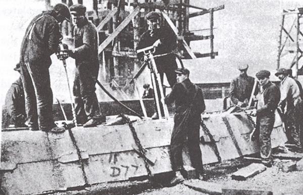
Daniel, I have no idea what that structure is in the background of the picture. I am guessing this picture is WWI vintage. I believe the tools being used are "Little David" pneumatic drill and hammer made by Ingersoll-Rand, probably introduced in th early 1900's, long after Young America. Tey were widely used in shipyards for drilling, driving caulking. If anyone has any data on these tools and when they were introduced, I would be very interested. Grant, the amount of time added to the lofting of each frame pairis minimal and well worth it. With the body plan profiles available, a pair of frames is being lofted in about 20-25 minutes, using a standard template worksheet fo development of the patterns and standard presentation/printing formats included. Adding indexed bolts adds a few minutes. I burn out after doing about 5 of these. Ed
- 3,618 replies
-
- 2
-

-
- young america
- clipper
- (and 1 more)
-
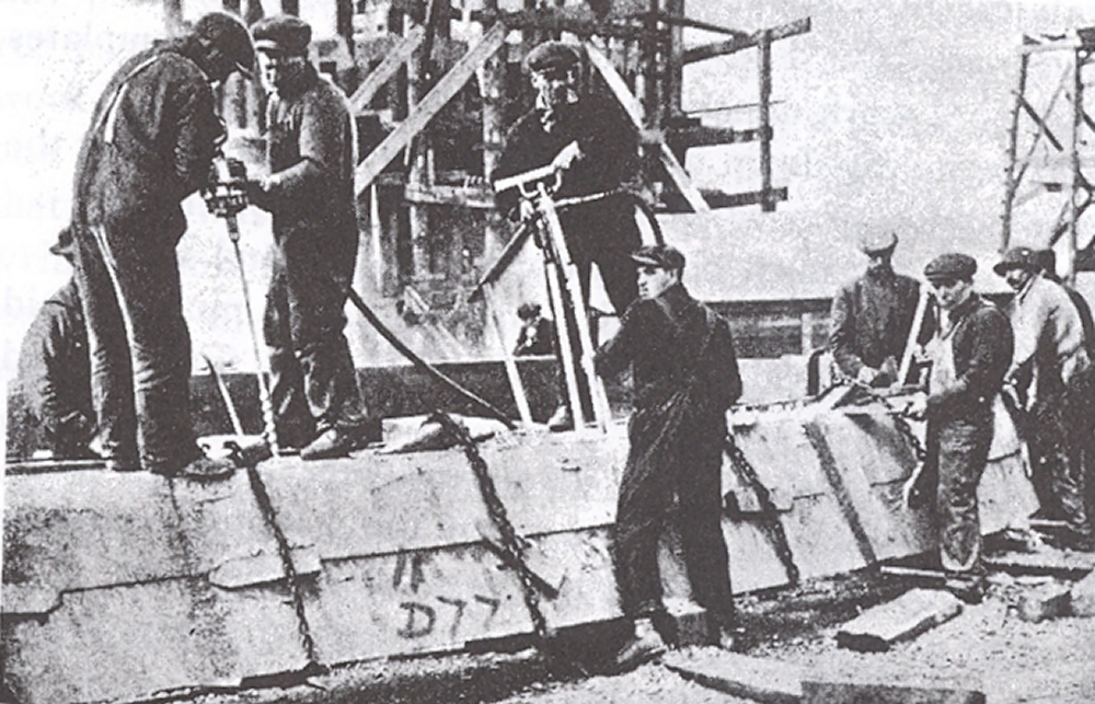
Sources I am using say that frame bolts were drilled and driven "normal" - perpendicalar- to the face and that is the rule I am following. So bolt placement becomes critical as the bevels increase - to the point where canting of the frames is required. Here is a photo taken probably 50 years or more after YA, showing that the rules had either changed or these guys were doing their own thing. I love these old shipyard photos. Also, the team in he center of the photo appear to be pneumatically driving treenails not bolts, but I could be wrong. Ed
- 3,618 replies
-
- 6
-
-
- young america
- clipper
- (and 1 more)
-
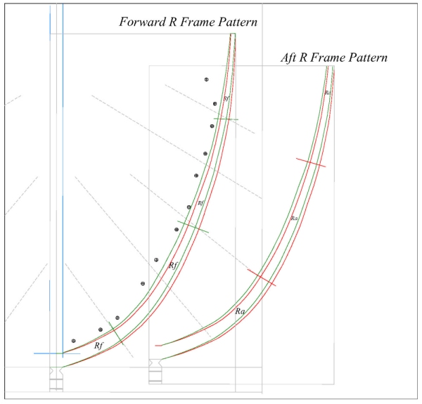
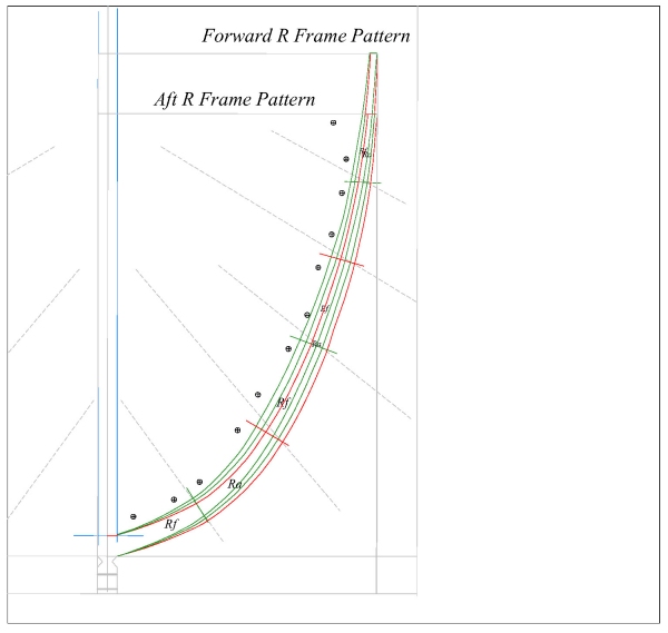
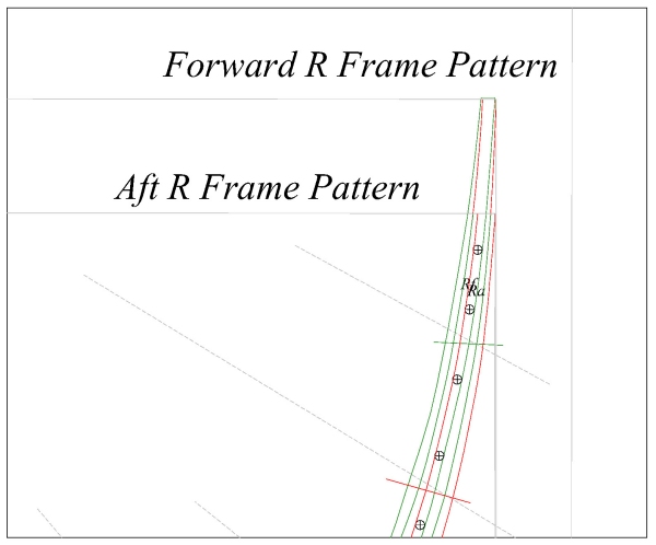
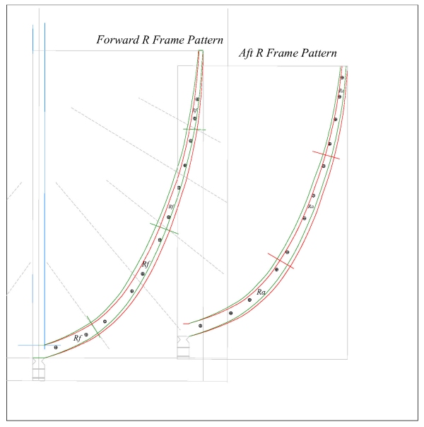
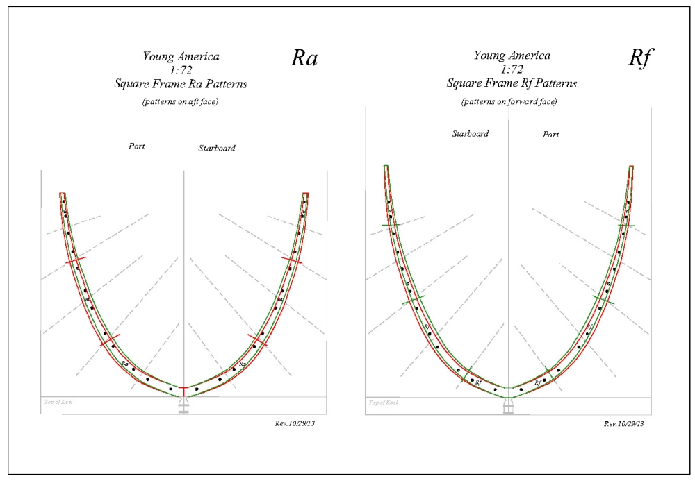
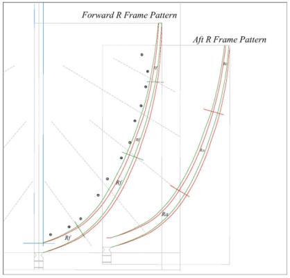
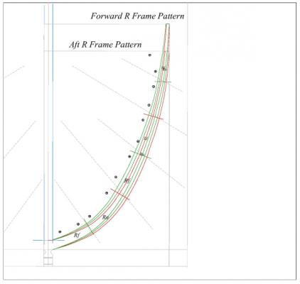
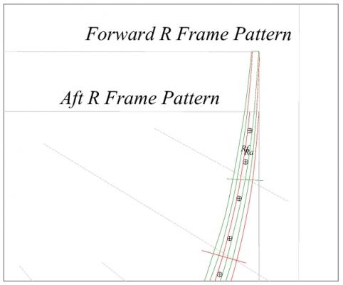
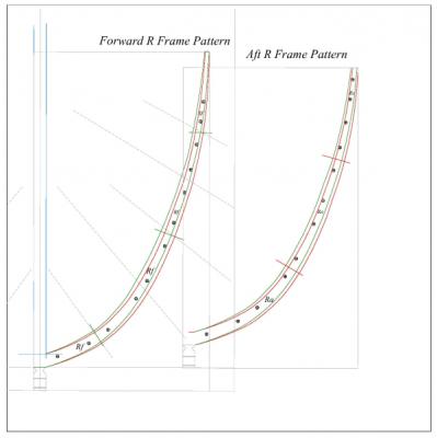
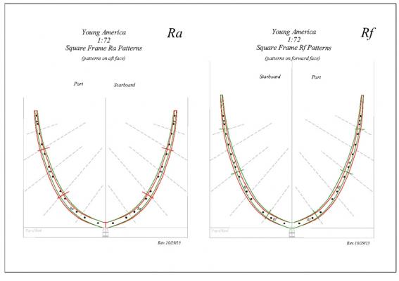
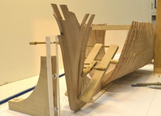
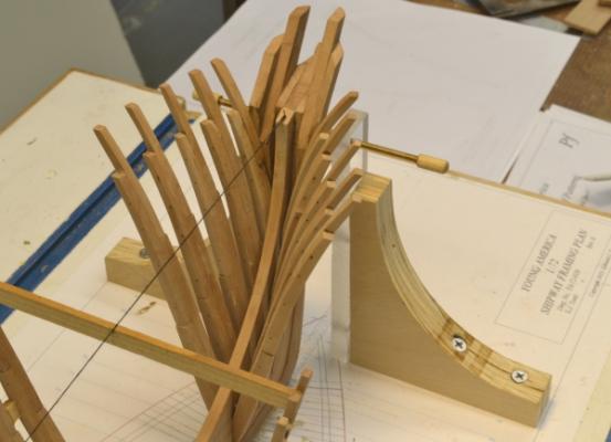
Young America - extreme clipper 1853 Part 28 – "Pin-Indexing" Next on the agenda is a long slog of repetitive work – making and setting the 29 full frames of the afterbody. This will be followed by 13 pairs of half frames and 6 pairs of cants – then the eagerly anticipated circular stern Essentially, this framing will be a repeat of the installation in the forebody. I previously showed pictures and described the frame assembly using pin-indexed pieces. This has greatly improved efficiency and accuracy in assembling the 13 pieces of each full frame pair. This process can only be used if indexed bolt/pin holes are provided on the pattern sheets. I thought it might be interesting to give a short overview of how that step in the lofting process was done. I put this post together a few days ago thinking I might post it. The discussion on pre-beveling of frames prompted me to do so, since the lofting described is one of the enablers for that. This is an overview only of the pin/bolt hole placement on the patterns. I will not describe the entire frame lofting process here, except to say that profiles for the true fore and aft faces of each frame must added to the normal body plan and used for lofting beveled frames. Using profiles from the next frame forward and aft does not provide sufficient accuracy for bolt placement in beveled frames. The first image shows the fore and aft half-pattern objects for forward frame R, created from the enhanced body plan. In each pattern green is used to show the forward profiles and red for the aft profiles. Every frame “bend” on Young America is constructed with offset, sistered fore and aft timber segments. The segments are delineated by the cut lines on each pattern. In this image no pin holes have yet been placed on either pattern, but the objects for the hole marks are scattered to the left of the forward pattern. The two patterns are then aligned to their final relative positions as shown below. This is a highly beveled frame pair, as can be seen in this image. With the patterns aligned, the pin/bolt hole objects are placed on the combined patterns between the line for the forward outboard profile and the aft inboard profile. This assures that they will not break through either the inboard or outboard faces – hence the need for accurate profiles. The placement of some of these near the top of the frame is shown below. In this highly beveled frame, these hole objects just fit between the lines. The actual pin/bolt holes will be smaller than these objects. Note that the top of the forward frame is higher since it includes the stanchion for the main rail. With the holes placed, the aft frame pattern object is selected along with all of the hole objects. This combination is then copied and pasted to the right in the next image. The aft pattern is then deleted from its position atop the forward pattern leaving just the forward frame and the original hole objects in place. The two pattern halves now have precisely indexed pin/bolt hole marks. The two objects in this image are then mirrored and combined to form the full frame patterns shown below. This same basic process is also used for the half and cant frames. After cutting out the timber segments, the patterns can then be used to drill indexing pin holes to locate the timbers on a pattern sheet for assembly and later for insertion of model bolts. This was described in previous posts. Assembly accuracy is very dependent on accurate drilling, but that is another topic. Besides the advantages in assembly time, the final frame emerges with patterns on both fore and aft faces – one of the important enablers for pre-beveling before erection. I believe this process has reduced the frame assembly time to half of what I expected so far. The above description is, of course, simply an overview, hardly a tutorial. The jury is still out on whether this and the other process features will enable frames to be completely beveled before erection. Sorry, no photos. Next time. Ed
- 3,618 replies
-
- 18
-
-
- young america
- clipper
- (and 1 more)
-
HMS Naiad 1797 by albert - FINISHED - 1/48
EdT replied to albert's topic in - Build logs for subjects built 1751 - 1800
Looking good, Albert. Ed -
Richard, The Naiad model described in the two volumes was always intended to be a structural model - aka a fully-framed model - of the hull. There is no plan to rig the model or for additional volumes. There are many good sources of information to assist in masting and rigging. There were standard specifications covering all of this for RN ships of various classes. Probably the best primary - meaning 18th Century - source for this is Steel's Masting and Rigging. Secondary sources include James Lees Masting and Rigging English Ships of War, Longridge's Anatomy of Nelson's Ships, David Antscherl's The Fully Framed Model Volume IV and others. The last two describe modeling. David White's Diana in the Anatomy of a ship series also describes masting and rigging for a ship of the same class and very similar to Naiad. Ed
-
Perhaps you are right, Druxey. I may be overly optimistic about this. As with most of this work, my attittude is: With the right process, even I can do it.
- 3,618 replies
-
- 2
-
-
- young america
- clipper
- (and 1 more)
-
Thank you all for your comments. Ben, it is never good to generalize, but I believe that it was not common on American clippers to fill the gaps between frames below the floor heads as was done in 18C RN ships like Naiad. Because the clippers used suction pumps that could reach to the inboard face of the garboard strake at the bottom outboard face of the frames, the spaces between frames along the keel could be drained. This could not be done with the chain type pumps used earlier so there would always be stagnant water between frames. On the clippers a roughly 3-4" limber channel was cut on the bottom of every frame near the keel to allow water to flow to the pump under the frames. These were normally fitted with chains so the debris could be cleared out as necessary. So-called "hogging chocks" were used on some ships between frames but these did not extend to the keel. These were wedged between the frames to put the hull structure into compression that would help resist hogging. Evidently these were used all the way up the frame, but I cannot see how any but those at the bottom would be useful. So, simple answer: no. Druxey, interesting point. You are quite right that the long sleek hull form would apparently reduce frame bevels. Your observation perked my interest because I have been struck by how few cant frames were used on YA as opposed to Naiad. YA has only six pair forward and the same number aft (19% of hull length). Naiad had the equivalent of 11 and 9 pair fore and aft respectively (34% of hull length). So, on YA the square frames (full or half) were taken much closer to the ends of the hull. On older ships much more of the hull curvature was taken up by cant frames - at least on Naiad, which I beleive is representative. Recognizing that ships differed, I looked at Naiad's most beveled frame, which turned out to be 24a, the last square frame aft. The maximum bevel on that frame was just under 20 degrees. On YA the most beveled frame is forward (surprisingly), frame Zf. The maximum bevel angle on this frame is just over 23 degrees. So, in fact, the frame beveling on YA is comparable, at least, perhaps slightly more and due entirely to using fewer cant frames. I really do not like the idea of beveling the frames by sanding the final hull shape. I did some pre-beveling of frames on Naiad, but it had to be limited because after frame assembly there was a pattern on only one side. With the assembly method used on YA, patterns remain on both sides and they are more accurately placed. This should permit beveling to be completed before frame erection - at least theoretically. I have been working up to that slowly - gaining confifence in the method. I have just started frames aft of 0 and I am beveling those right to the line. We'll see how that works out. Thanks for raising this interesting point. Ed
- 3,618 replies
-
- 1
-
-
- young america
- clipper
- (and 1 more)
-
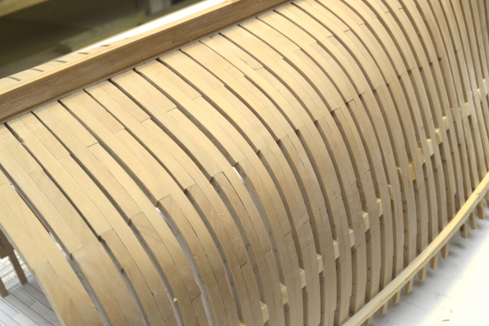
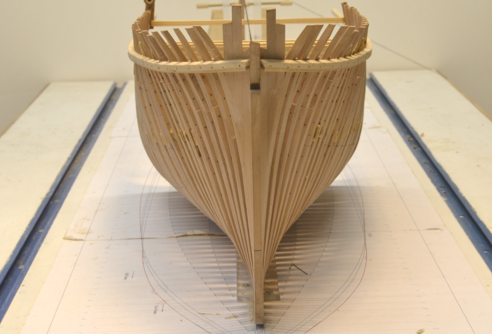
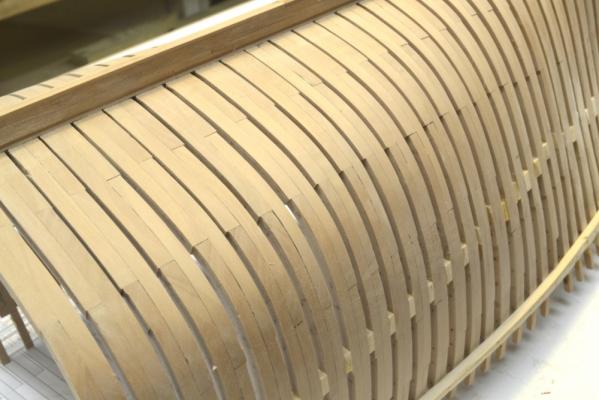
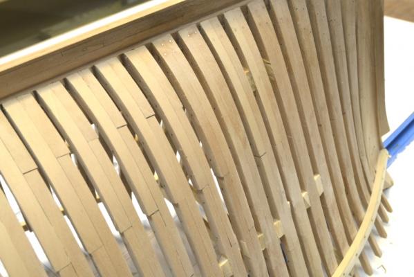
Young America - extreme clipper 1853 Part 27 – Forward Hull Sanding/Bolting First, thanks everyone for the recent comments. I hope all those who celebrate Thanksgiving Day had a good holiday. The view from directly forward in the last post seemed popular so here is another from a slight angle. All those unsightly wood spacers between frames are temporary and will be coming out at some point. After this picture was taken the model was inverted for fairing and sanding. There is not much to say about this, since it turned out to be less work than anticipated. Below is a picture of part of the bottom after sanding. Not much fairing was needed – nothing like the work I had to do on Naiad, where very little pre-beveling of frames was done. On this model almost all of the beveling was done before the frames were set, so the sanding was mostly for cleanup and finishing. The next picture shows an area slightly forward. This picture shows some of the bolts – inserted after sanding – to secure the half frames to the keelson/deadwood. These are copper wire, epoxied deep into the holes to give strength to the model joints. These frames are end-grain glued to the keelson/deadwood, so the joints are not strong. These bolts were iron so they will be blackened before the lower hull is finished. I am considering installing the garboard strakes – at least – later on both sides. On these ships the garboards had an important structural role. They were quite thick (7”) and were edge bolted through the keel and face bolted to the frames. This reinforced the attachment of the frames to the keel and will serve that purpose on the model as well. You will recall that the frame floors are merely glued and pinned to the top of the keel – not notched to fit over a rising wood as in 18C ships – and some clippers. This is not a strong joint. While the model was inverted the remaining forward bolts were installed. The bolts through the stem can be seen in the next picture. These were long copper bolts. Eventually, the forward side of the stem – actually the false stem – will be tapered down to about 4 or 6 inches in `breadth. The last picture shows the iron bolts securing the hawse timbers to the stem/apron. Like the cant frame bolts, these are black monofilament. All these bolts were riveted flush. The model has now been re-aligned on the shipway so the afterbody framing can begin. Ed

- 3,618 replies
-
- 34
-
-
- young america
- clipper
- (and 1 more)
-
Thank you, Allan. And Druxey - spot on! Falconer's 18th C Universal Dictionary of the Marine: "Cambered-Deck, the deck or flooring of a fhip is faid to be cambered when it is higher in the middle of the fhip's length and droops toward the ftem and ftern, or the two ends." Whatever will we all do with this (relatively) useless knowledge. Daniel, you have awakened us all out of our post-holiday slumber. Cheers, Ed
-
Smac, I am glad to hear of your Naid build and I believe you will be pleased with Volume II. Thank you for the support. I would love to see your progress. Why not start a build log on MSW? Ed
-
Thank you, Daniel. With regard to terminology, please keep in mind that I use that of the time and place, in this case the 18th Century England, so terms will often differ from those of today. "Round up" was the common usage at that time - in contracts, marine dictionaries, and Naval Architecture references. I am sure there are many instances of this in the books and in my postings on this site. I have still not absorbed all of the American mid 19th century terms that apply to YA. An example is "shoe" vs. "false keel". Another - "fancy rail" vs. "roughtree rail" I could go on. As far as YA's configuration is concerned, one side will be left unplanked to reveal the structure. I may leave some viewing panels on that side open to view the internal structure. I have not decided whether to plank and sheath the starboard side. I may leave it in frame below the waterline. I am leaning toward rigging but have not yet decided. Stay tuned. Ed
-
So, on Thanksgiving morning, I just have time to say thanks for these compliments and to everyone who has made comments and watched Young America as she emerges from that large slab of swiss pear in my workshop. Your following is very much appreciated. Now, time for real work. Where is that vacuum cleaner? Ed
- 3,618 replies
-
- 3
-
-
- young america
- clipper
- (and 1 more)
-
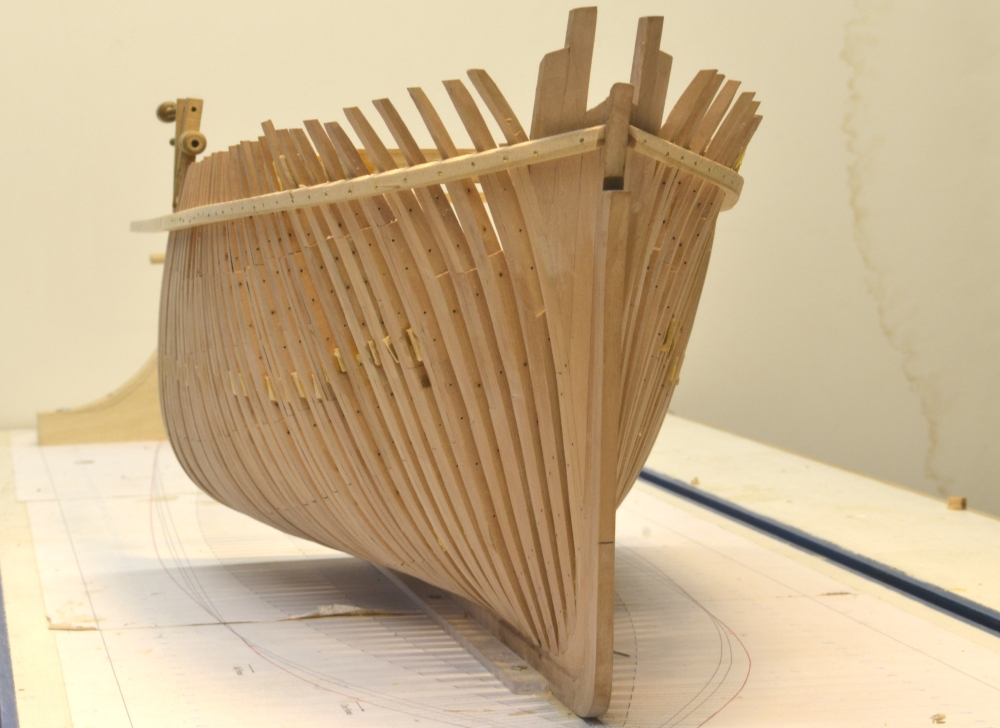
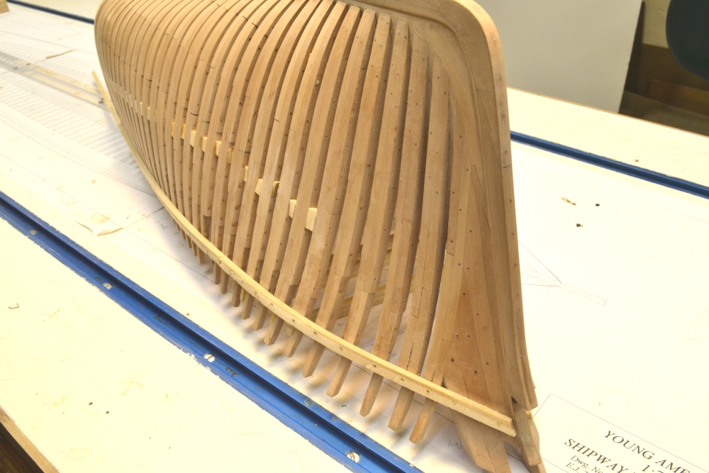
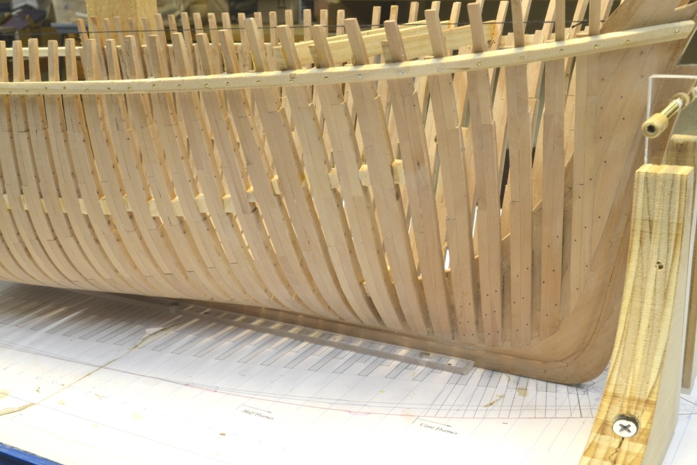
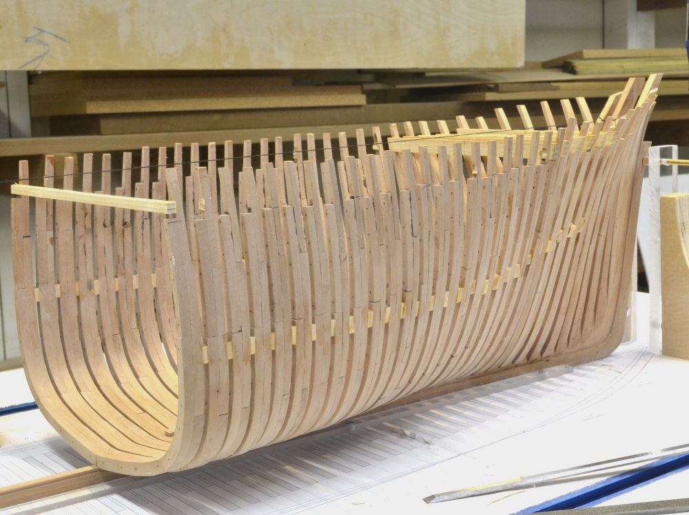
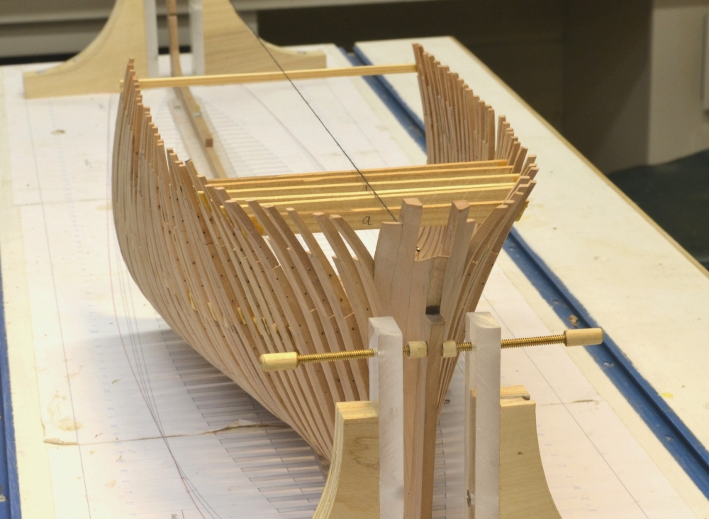
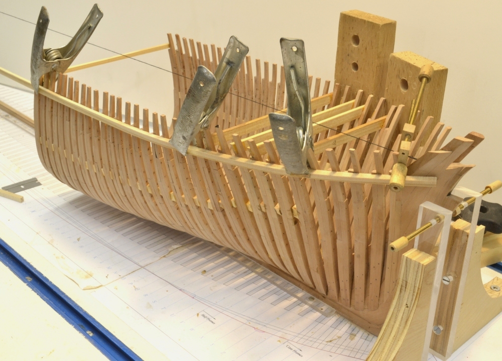
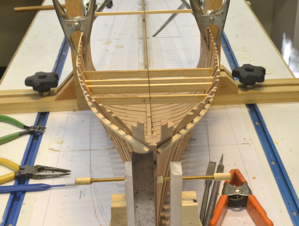
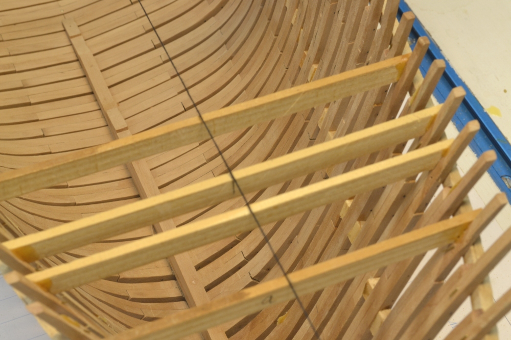
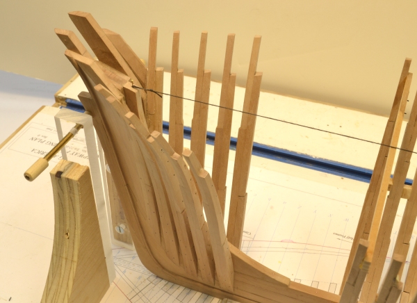
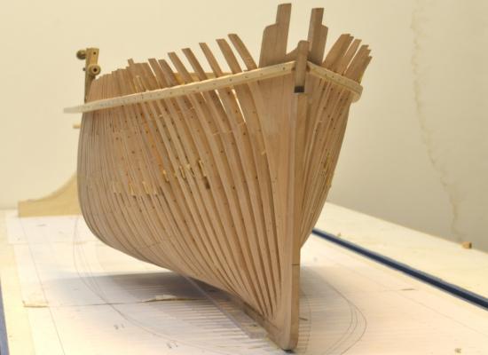
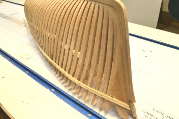
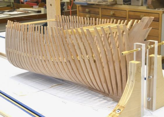
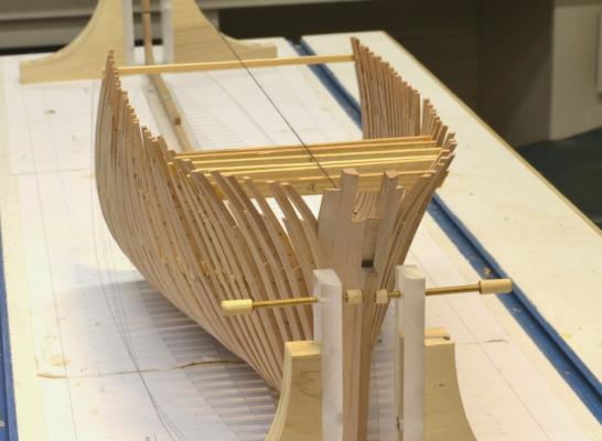
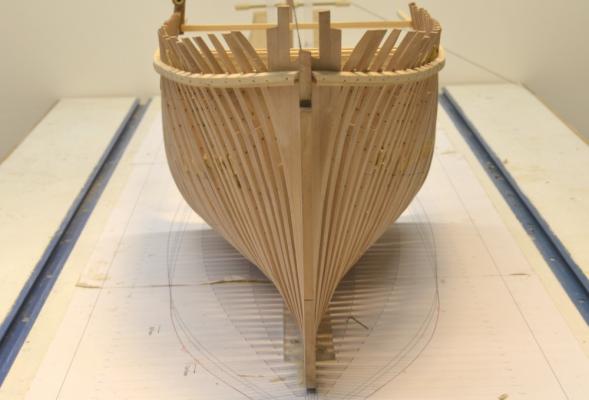
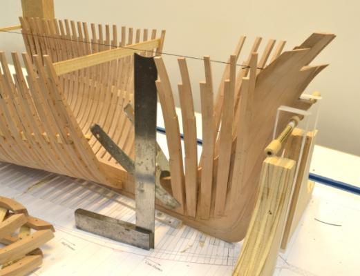
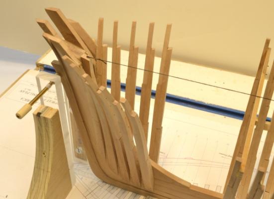
Young America - extreme clipper 1853 Part 26 – Forward Half Frames/Ribbands To provide space for work on the forward cant frames, I deferred setting of the remaining half frames. In the first picture that work is proceeding. The next picture shows all of the forward frames installed. The sleek forward hull shape is really visible at this stage. The next picture shows a different perspective. And another view. At this stage the alignment and spacing of the frames are set by the softwood spacers between each frame about midway between the keel and topside. More strength is needed for final fairing of the lower hull. Also, as the above photo shows, there is some irregularity in the line of the toptimbers that needs to be corrected before final fairing. I decided to fair the forward hull before proceeding to the aft frames. To provide additional strength and align the frame tops I installed temporary “ribbands” on both sides at the height of the planksheer. I found this a very useful device in constructing Naiad. The next picture shows the starboard ribband being fitted. These were made from single 3/16” strips of clear white pine. One end was boiled to set the curvature and in the above picture is being clamped for drying. In the next picture installation is proceeding. The strips are secured to every frame by short pins through drilled holes. These are bent over on the inside to pull every frame tightly into the fair line of the ribband. I cut off the points of the pins before bending to avoid all the scratches I got from these while working inside Naiad. The holes in the frames will later be used for sheer strake bolts. The tops of the strips are set at the height of the bottom of the planksheer rail, so these can be used to trim off the tops of the aft upper futtocks. The next picture was taken from above after the strips were installed. The center marks on the cross-spales cannot be seen under the thread line. This is a good thing. In addition to this centering check, the outside of the ribband was also checked by squaring up from the base drawing. In the next picture I cleared all the clutter from the shipway to focus on the lines of the very sharp forward entry. At this stage the frames have only been given the bevel described earlier before they were set. Some additional sanding to refine the fairness is needed. The model can now be removed from the base and upended for sanding and also for installation of quite a few bolts, especially those holding the half-frames to the deadwood. These joints are quite weak so the model bolts will have to provide strength. I will cover this in the next post. Happy Thanksgiving everyone. Ed


- 3,618 replies
-
- 26
-
-
- young america
- clipper
- (and 1 more)
-
Looks, geat, Gary. Glad to see you posting again. Ed
-
Frank, I neglected to respond to your comment on the string line. This, combined with centermarks on the upper cross-spales may be the single most important tool in maintaining alignment in models built upright. I had previously used thin wire wrapped taut between two pins, but found it always in the way and a pain to move and replace. Thread held taut with a hanging weight is a simple and easy to apply solution that can be moved without bother when necessary. These features help assure that it will be used. Highly recommended. Ed
- 3,618 replies
-
- 4
-
-
- young america
- clipper
- (and 1 more)
-
Thank you all for these kind words. The lines are indeed sweet, Druxey, a fact that I can take little credit for. The beauty of the full forward hull shape will become more apparent in the next post as the remaining forward frames are placed. I really appreciate the comments on the bolt pattern. This is one case where the bolts actually compliment some of the attractive structural lines. The top row parallels the cutting down line and the lower row the bearding line. This is structurally correct and aesthetic at the same time. Unfortunately this is not always the case as many authentic bolt patterns appear quite random - and often, on models, sloppy. I am sure there will be plenty of such cases on this model. On Naiad I learned that while this effect of realism cannot be eliminated, with care it can be moderated. There is always something to learn. Thanks again. Ed
- 3,618 replies
-
- 2
-
-
- young america
- clipper
- (and 1 more)
-
...and thank you, David. The screw clamps are home made. The are generally described in the MSW Naiad posts and complete dimensioned drawings are included in the book, the Naiad Frigate, Volume I. Ed
-
Thank you both. Greg, the reduction of the images to 600 pixel width is a throwback to the old site limitations. I will up the resolution for posting in future, but for a number of reasons I prefer not to post at the full original resolution. Ed
-
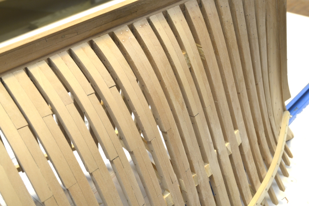
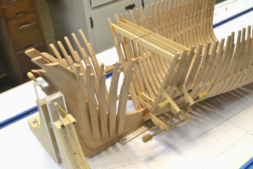
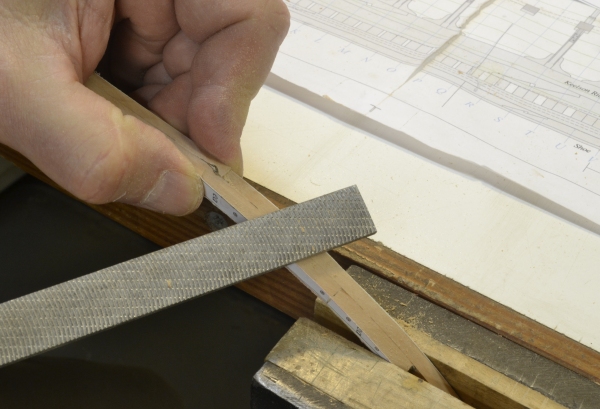
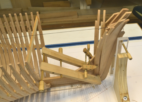
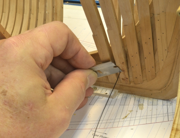
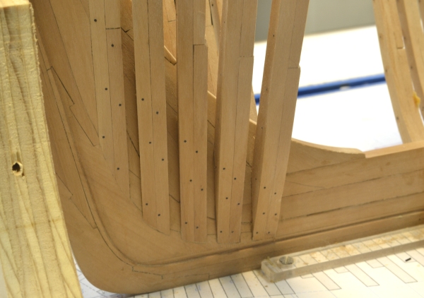
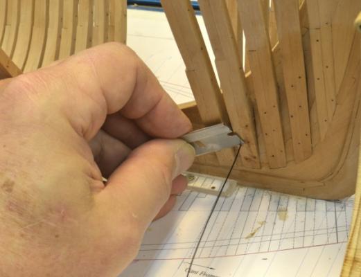
Young America - extreme clipper 1853 Part 25 – Forward Cant Frames 2 American Clipper Note: William Webb foresaw the end of the extreme clipper craze. He came down to the dock to see Young America off on her first voyage in 1853 and remarked to the mate, “Take good care of her Mister, because after she’s gone there will be no more like her.” (Dunbaugh) Webb turned his yard to the future. Young America was his last extreme. Within the next few years there was a glut in clipper capacity and the premium freight rates they had enjoyed dropped off, ending demand for the type. Some were slow to see the change, but Webb’s yard continued to prosper building medium clippers, steamships and even a huge ironclad, finished too late to enter the Civil War. This part will bring the forward cant framing to completion. All of these frames were almost completely beveled before installation, as I became more comfortable with accuracy of the pin-indexed assembly. With patterns left on both faces of the assembled frames, each could be cut back to the green lines on the forward face and the red lines on the aft face using disk and spindle sanders. The sides were then shaved flat to those lines as shown below, using a carver's rasp. This tool leaves a very smooth surface requiring little or no sanding. The work can be held by hand and/or with the aid of a vise. The next picture shows the clamping of the second frame on the port side. The clamping of these can be awkward, requiring long-reach clamps and gripping of angled surfaces. A starboard side frame is being installed below. In the next picture the last frame is being installed – with simpler clamping. The position of each frame was checked with the square from the base drawing when glued in place. Although the bevel angles of the joint faces were put on each pattern during lofting, there was still need for some refinement to get the proper installed angle. Each mortise also required some trimming for a good final fit. With all the frames installed, fair lines for the bolt holes were drawn and the simulated iron bolts installed. In the next picture a black monofilament bolt is being cut off at the surface after gluing. The excess CA glue was washed off with acetone and the bolts leveled off with a file. The next picture shows the finished bolting on the port side. The last two pictures show the finished bolting - six 1 1/8" iron blunts per pair driven flush.. The thread line seen in these pictures was used to center the half frame pairs. It is hung by a weight off the center of the sternpost so it can be pushed out of the way or removed when required. In the next part the remaining half-frames will be installed, completing the frame setting of the forward hull. Work is progressing much more rapidly than I expected. I think this is mainly due to the pin-indexed frame assembly and the improved beveling method. Ed


- 3,618 replies
-
- 28
-
-
- young america
- clipper
- (and 1 more)
-
Rob, As I have said, there is clear documented evidence - for example 20 years of American Lloyds Registry listings - that YA was iron strapped - not at issue and not a guess. By the way, if you look at Table 12.1, p. 198, in Crothers, you will see that McKay used iron bracing as well. My statement(s) about Webb using lighter structures is based on the many diagrams and tables in Crothers book as well as drawings and other sources that list timber sizes and layouts. Have a look. I do not believe that Webb was "fond" of less wood, but rather that he was confident in the sizes and designs he used and that confidence was justified by the performance and longevity of ships like YA - 30 years, 50 trips around Cape Horn - pretty good. I call this good engineering. I admire it and the courage it takes to pactice it. This attracted me to Webb. No criticism of McKay or any other builder is intended. As to the question of whether sufficient information is available to build an authentic structural model of Young America, the answer is yes. If this were not the case, I would not be building this model. I am usually pretty up front in the postings on sources and where any discretion has to be applied. For the configuration and details of iron strapping, I would refer you to Crothers, p, 197. I will discuss the strapping on the model when we get to it. I think we have beaten this subject to death on this log. Perhaps this would be a good topic in the Research section. With your permission, lets move on. Ed
- 3,618 replies
-
- 3
-
-
- young america
- clipper
- (and 1 more)
-
Rob, Forgive me if my comments on cross-bracing were confusing or unclear. I do not believe I have ever disputed that wood cross-bracing was used on American clippers or that Donald McKay employed it in his designs. In fact, when I was initially researching clippers in search of a subject, I found it on the drawings for Lightning made by Bill Crothers based on McKay's extensive papers. Also, Crothers book on American clippers, Figure 12.4, pp 210-211, also shows it, if you have the book. The unamed ship in this drawing is in fact Lightning. Crothers book and other sources make it fairly clear, I believe, that Webb and McKay took some different approaches in strengthening their hulls. The differences and similarities between the two builders are of interest to me, of course, but I am mainly focused on Young America - a Webb ship. Ed
- 3,618 replies
-
- 1
-
-
- young america
- clipper
- (and 1 more)
-
Nice work, Rob. Ed
-
Thank you for the comments and for all the "likes". Bruce, the stern will be the most interesting construction in the framing. Going aft from the already installed midship frame, there are 29 full frames, then 13 pairs of half frames and finally 6 cant frames. The circular stern is the formed by four radial counter timbers on each side supported off the last cant frames - sometimes called the fashion pieces. The two frames at the center are parallel to the keel and bolted to the sides of the deadwood and sternpost. I decided to use this transomless stern, which was one alternative. Again no specific original design data is available, but I believe this type was common on ships of his size. Elia, the iles and rifflers I use most often are Grobet - generally coarse cut #0 on wood. They are a top quality Swiss-made file and somewhat expensive, but I really only use a few. Below is a link to one source that has most of the line. Since I rarely throw a tool away, I have a ton of others in various sizes, but the ones you will see most often in the pictures are Grobet. http://www.contenti.com/catalog.html Ed
- 3,618 replies
-
- 1
-
-
- young america
- clipper
- (and 1 more)