HOLIDAY DONATION DRIVE - SUPPORT MSW - DO YOUR PART TO KEEP THIS GREAT FORUM GOING!
×


EdT
-
Posts
2,213 -
Joined
-
Last visited
Content Type
Profiles
Forums
Gallery
Events
Everything posted by EdT
-
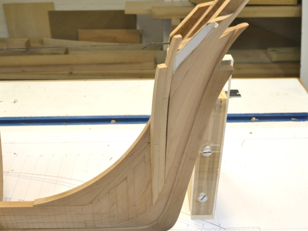
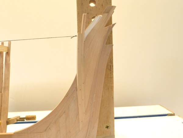
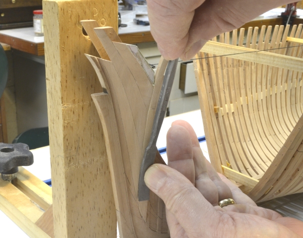
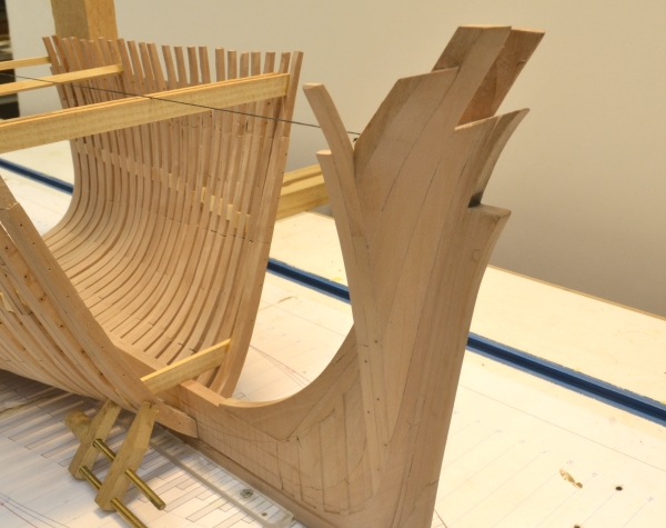
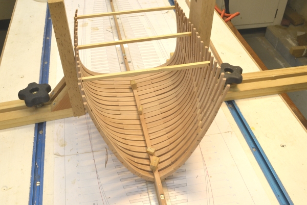
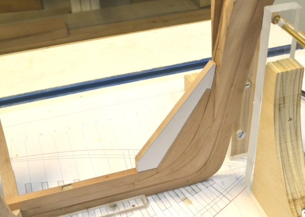
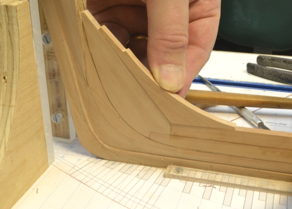
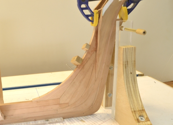
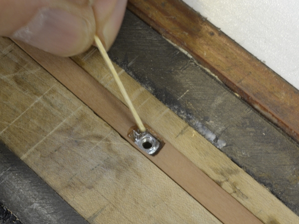
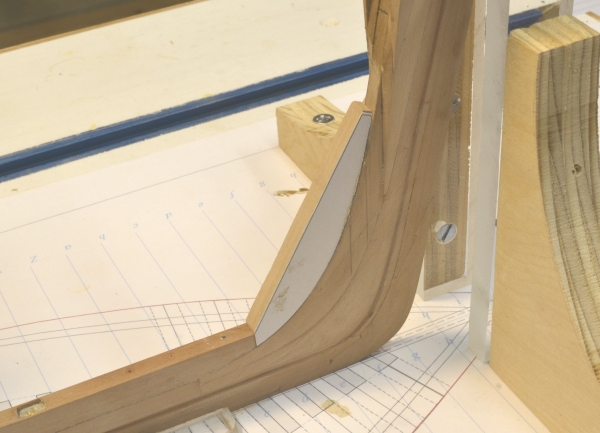
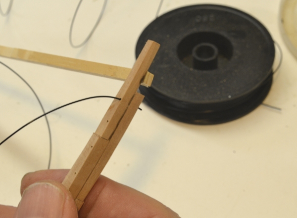
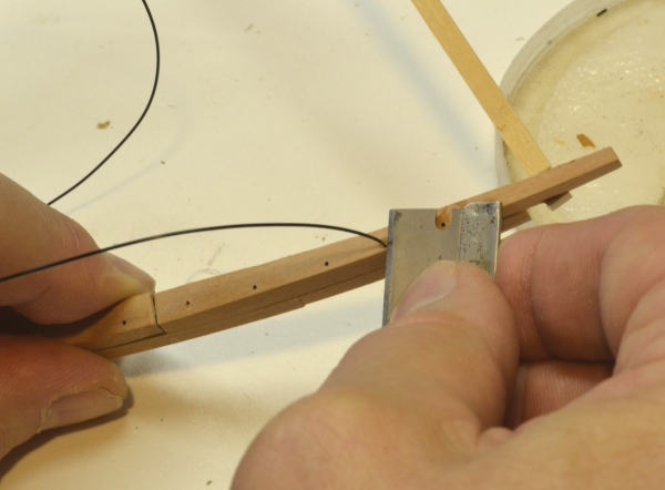
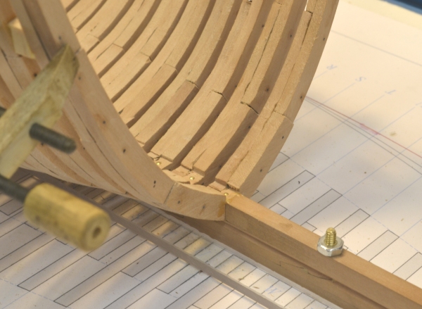
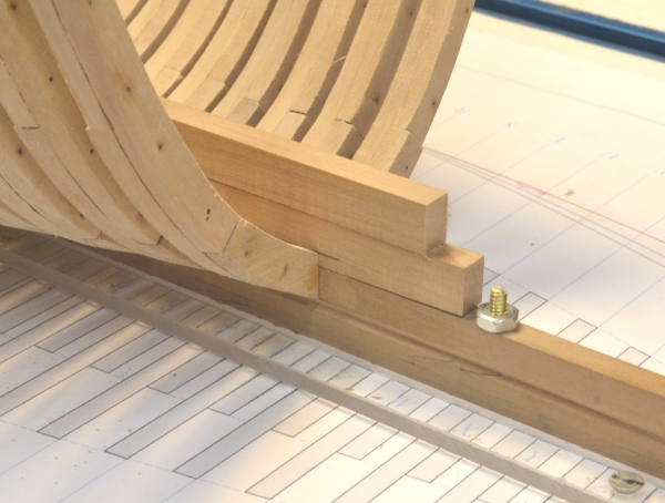
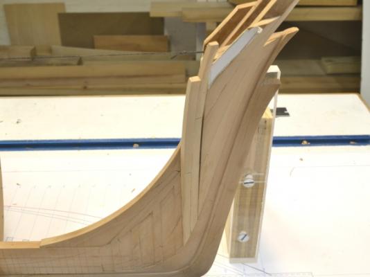
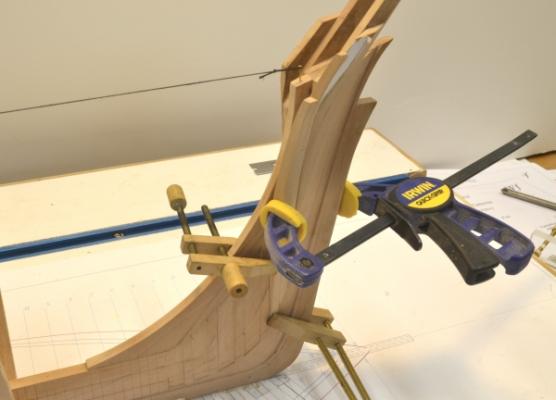
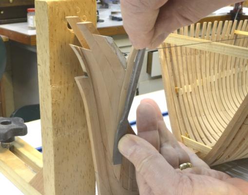
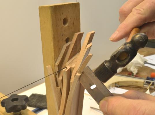
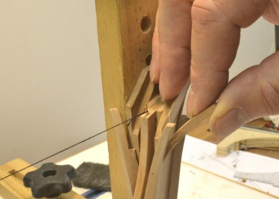
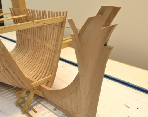
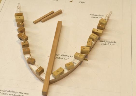
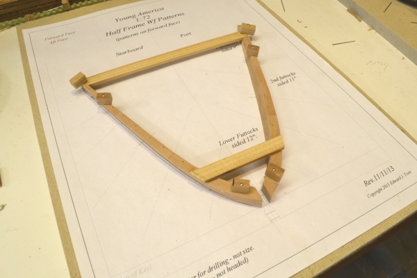
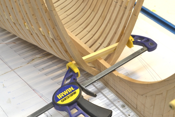
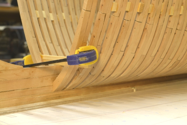
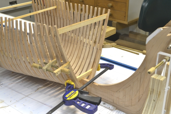
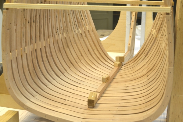
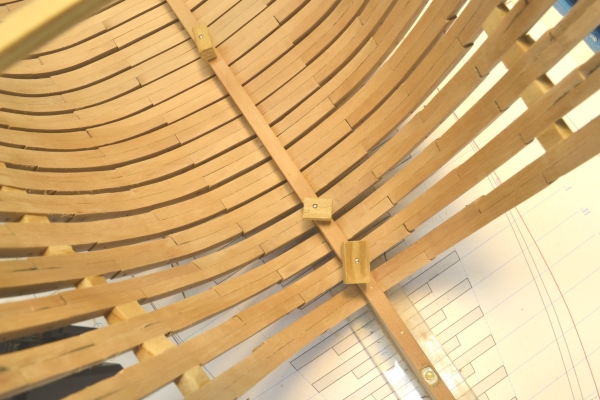
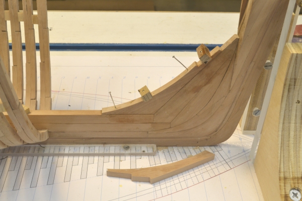
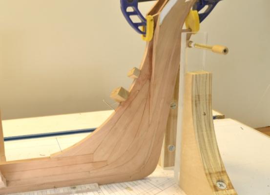
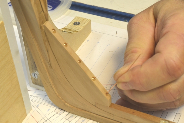
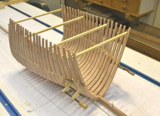
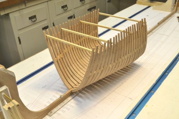
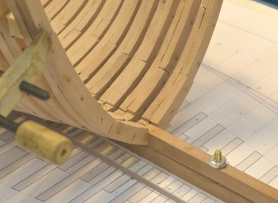
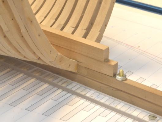
Young America - extreme clipper 1853 Part 24 – Forward Cant Frames American Clipper Note: American Clippers not only sailed fast, they were built fast. Impatient customers demanded it. A yard would normally launch two from the same slip in a year. Many were built in close to three months time and one 200-footer, John Bertram, in 61 days. There were a number of reasons for this productivity. First there was increased division of labor and the creation of trades. Gone was the all-around shipwright in favor of gangs for specific tasks. Steam driven machinery was widely deployed. McKay, and perhaps other large yards, used steam driven bevel-saws that could be adjusted to the angle of the frame bevel while running. This alone cut frame fabrication time by a factor of six, using but three men. Steam derricks were used to raise frames and other heavy timbers, vs. a common practice of everyone dropping what they were doing to lend a hand. Making treenails was no longer a rainy day make-work job done manually with axes and spoke shaves. Instead treenails were rapidly turned out in by steam driven lathes. Back in the model shop, the all-around shipwright plods along. The first picture shows the most forward cant frames being assembled. Exactly the same pin-indexed alignment method is being used. After assembling these roughed out pieces, the frames are beveled and the patterns removed. The sidings of the upper futtocks are then reduced and the bolts installed. In the next picture this has been done and the starboard frame is being fitted up into the mortise cut for it earlier. Some paring of the mortise sides and bottom was done to neatly fit the frame. In the next picture, the clamping has been set up in preparation for gluing the frame in. The clamps were then removed, glue was applied and the clamps replaced. After drying, the clamps were removed, the frames faired and the six iron bolts into the deadwood installed, as shown in the next picture. Stem supports had to be removed for much of this work – usually one side at a time. In the next picture the port frame has been installed and is being faired with a flat riffler, followed by sanding. No project is without rework. I have normally been making toptimbers from smaller 9-inch stock so these very visible members will be consistently sized - unlike lower timber sidings that have been filed or machined back after pattern removal. In the case of these first cant frames, this reduced siding at the top left a small gap at the adjoining hawse timbers that can be seen in the last two pictures. This was an oversight when I lofted the frames. Rather than delay the erection, I decided to install the frames, then replace the toptimbers - before the glue had set overnight. The next picture shows the starboard toptimber being removed with the aid of a razor blade in the glue joint. No glue was applied on the forward side of this piece, so it was easy to separate with light taps along the joint. The next picture shows the piece being removed, essentially intact. In this picture the port side toptimber has been removed and not yet replaced. In the last picture the new larger top timbers have been installed and the joints with the hawse timbers closed up. Installation of the forward half frames has been suspended until all of the cants are in place – to leave room for that work. Ed


- 3,618 replies
-
- 25
-

-
- young america
- clipper
- (and 1 more)
-
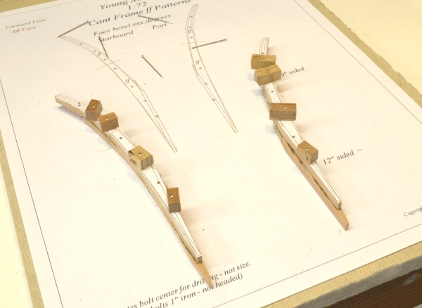
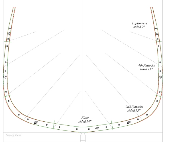
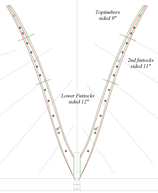
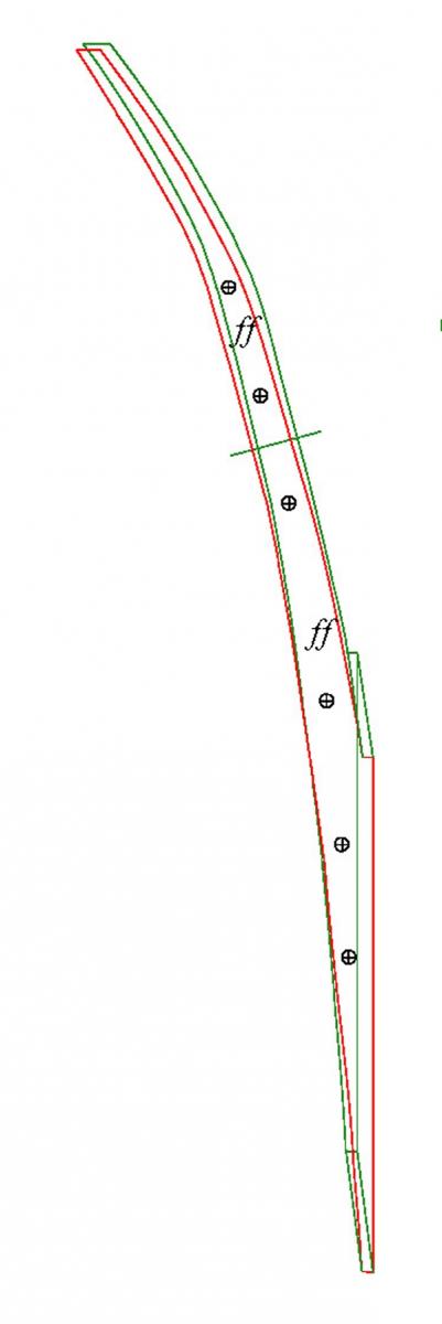
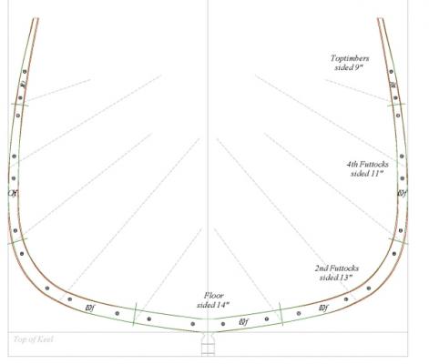
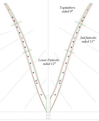
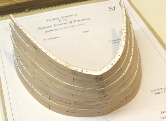
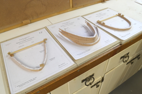
Young America - extreme clipper 1853 Part 23 – Forward Half Frames American Clipper Note: In the last part, the three types of frames were discussed. To shed some further light on that subject, before moving to the half frame work, I have included some images pf patterns that illustrate the types and also the way the shape of Young America’s hull changed from midship to the bow. The first image shows one of the midship patterns. Young America had relatively flat floors for an extreme clipper compared to the early versions like Griffith’s Sea Witch, McKay’s Staghound or Webb’s own design for Challenge. In all these ships the angle of the lower timbers to the turn of the bilge was much greater giving the midship a pronounced V shape. By 1853, designers were learning that extreme deadrise did not contribute to speed to the degree previously thought. Later extreme clippers had fuller bodies, like the one shown above. Moving forward the next image shows frame a, the most forward of the half frames and the last one going forward to be set at right angles to the keel. The most striking feature of this pattern is the extremely sharp v-shape of the hull at this point – a defining characteristic of all the extreme clippers. Notice that the frame is in two pieces separated by the keelson in the center. These will be bolted to the sides of the keelson. Also note that the bolt holes are becoming perilously close to the forward (green) outer profile at the top. This is necessary on this highly beveled frame pair so the bolts can be driven through this forward frame of the pair and not break through the inside profile on the aft frame. Some are actually over the line, but remember that the sidings on the upper segments are reduced so the bolt holes will actually be inside of the profile when the sidings are reduced. The pattern is at the forward face of the wider floors. Finally, the most forward cant frame, f, is shown below. This pattern shows the extremely narrow section just aft of the hawse timbers. This frame, when assembled with is aft partner, will fit into the forward score of the five cut out in the last part. So, with that background the installation of the forward frames may be less confusing. The first picture shows assembly of the two sides of the first half frame pair. The vertical strip between the frames was used to size the separation at the keelson for an easy fit. Next is a picture of a later frame with two horizontal temporary cross-spales to allow the frame to be installed like a full frame. This is much easier than dealing with two separated frames. Unfortunately the first frame was a bit loose on the keelson, so the bottom cross-spale was removed and replaced with two pieces, each glued only on one opposite side. This allowed the joint at the bottom to be closed up with a clamp as shown below. The next [picture shows a close up of the other side during assembly. Note that the bottom of the frame is aligned with the top of the keel rabbet. The lower cross-spale resting on the keelson was installed to set this height. When the glue had set at the keelson, the usual spacers were installed above to maintain spacing and adjust the centering – as shown in the last picture. In the next part, the most forward cant frames will be set. Ed

- 3,618 replies
-
- 14
-
-
- young america
- clipper
- (and 1 more)
-
Thank you, Wayne. I am familiar with these drawings and have been spending a fair amount of time going through the registers. For those not familiar with these, they were for the purpose of classifying ships for insurance purposes. They set construction standards for each category of risk and presumably classified ships on that basis. The New York Marine Register soon became American Lloyds Register (1859). These registers, each year, listed every American merchant vessel, assigned its classification and noted basic contruction parameters - including some details like the iron strapping that has been discussed here. This first Register in 1857 was issued three years after the launching of Young America, so her construction was not governed by the standards, but each year she was classified at the highest level - A1. To what degree she complied with the later standards is open to question. It is pretty clear that before the issue of these standards, American builders, owners and underwriters were essentially on their own - probably relying more on the reputation of the builder than construction standards. Lloyds (Britain) standards were known and available but did not govern American ships, nor did Lloyd's register American ships, even apparently, those in British ownership. Also, there was still post-revolution tension between the countries and America was flexing its muscles as an independent nation. The question becomes: Did ships like Young America influence or provide some of the basis for the standards and to what degree? I believe they are quite representative with some exceptions. Daniel, thanks again for your compliments and for your continued interest. Ed
- 3,618 replies
-
- 1
-
-
- young america
- clipper
- (and 1 more)
-
H Maury, I use ordinary Elmer's school paste sticks available in every supermarket or drugstore. Applied to the back of the pattern only, the patterns adhere well and they are easily removed by wetting with water, waiting 15 seconds then rubbing or scraping them off They come off very easily when wetted - almost fall off. Any remaining glue residue - usually minimum at most - can be wiped off with a damp paper towel. Ed
- 3,618 replies
-
- 1
-
-
- young america
- clipper
- (and 1 more)
-
Elia, I hope you are right on the angle effect, but in any event that edge will be easy to pare back when fitting the frame. The forward frame edge will be squared off. I have just about decided to proceed with the cant frames next starting at the front. This will provide more space for the fitting work and will also allow the frames to be bolted up as they are installed. There is some lofting work needed to do that. Thanks for your interest. Ed
-
Again,thank you all for the generous comments. Again, its always easier to do this kind of work when it is held down flat at the workbench with good overhead light. I could have done this but it would have required some fancy support due to all the frames that are already installed - and needed to be installed before constructing the deadwood. Actuually this work turned out to be less difficult than I expected. I did have to remove the stem support bracket on one side at a time to get room for the chisel forward. Elia. the locaton of the sides of the scores were squared up from the points on the base drawing where the cant frames intersect the surface of the deadwood. The width of the score is therefore based on the width of the beveled "foot" of he frame pair. I did not attempt to slant the side of the score to match the cant of the frame. I expect there may need to be some adjustments needed to fit the frames neatly whe the time comes. The most canted frame - the forward one - is only angled about 17 degrees forward. I do like to mimic the shipyard when I can. Ed
- 3,618 replies
-
- 2
-
-
- young america
- clipper
- (and 1 more)
-
Thanks, Druxey. I would have definately prefered to do this at the bench, but the order of construction got in the way. On these ships the keelson ran straight to the stem with the deadwood built on top. So the deadwood had to wait for the keelson and the keelson for the forward square frames. The assembly at this stage is pretty awkward on the loose. I considered dispensing with the scores, but I keep saying this is a structural model, so....
- 3,618 replies
-
- 3
-
-
- young america
- clipper
- (and 1 more)
-
Thanks, Greg. Fortunately these recesses will be covered and don't have to be perfectly finished inside - just flat. Fine finishing would have required the work to be moved to the bench to get chisel clearance on all sides. I expect there may be some moinor adjustments needed when the cant frames are fit. Ed
-
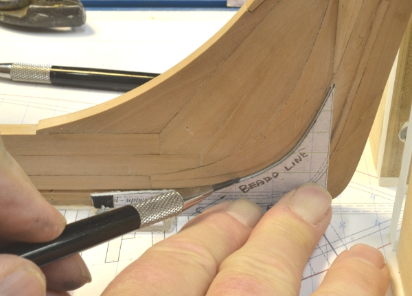
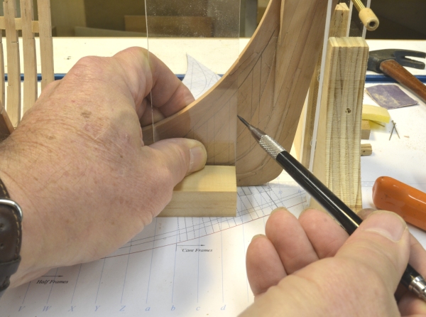
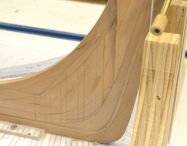
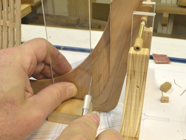
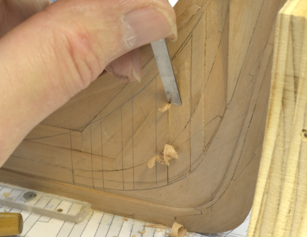
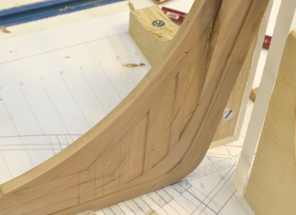
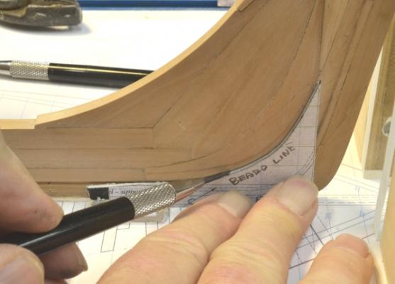
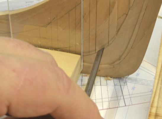
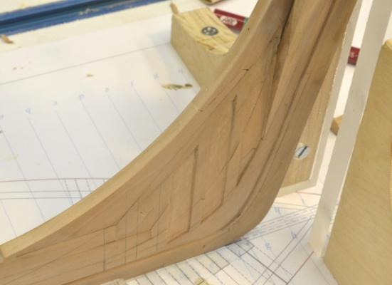
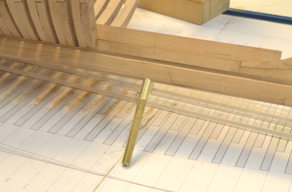
Young America - extreme clipper 1853 Part 22 – Cant Frame Scores American Clipper Note: In a departure from the historical notes on the stirring adventures of these ships in service, I thought it would be a good idea to comment on some construction aspects as well. Since the forward framing is set to begin on the model, some description of that might be appropriate. The bulk of the transverse hull framing on these ships – and most ships – consisted of full breadth “square frames” whose lower timbers rested on and were bolted through the keel. As the forward (or aft) end of the ship was approached and the v-shape of the floor timbers that crossed the keel became more acute, a point would be reached where naturally grown “compass timber” could not be found to make these pieces. At that point – on these ships – “half frames” were installed. These were still square to the keel, but were made in separate assemblies for each side of the ship and were bolted horizontally through each other and the vertical deadwood/keelson structure – the backbone of the hull. Further forward, as the bevels on these frames became more pronounced, it would no longer be possible to bolt the sections of each half frame pair together with bolts “normal” or at a right angle to the face of the frame, without the bolt being exposed through the beveled side. At this point “cant frames” were used to complete the bow (or stern) framing. These were also bolted to the deadwood but were angled – canted – forward to reduce their bevel and allow the pairs to be bolted together securely. Since every ship had a different shape and since timber availability varied, it seems likely that these break points were set for each ship in the mold loft as the frame patterns were drawn out and timber supplies known. I applied this assumption in lofting the frames for the Young America model. Before starting work on the next frames to be installed – the forward half-frames – the “scores” for the cant frames needed to be cut while there was still enough room to do this. These scores provided important support to the angled cant frames by allowing them to be inset into the keelson/deadwood – rather than depending on bolts alone. The vertical joint faces of each half-frame and the cant frame extend up from the bearding line to the cutting down line. The bearding line defines the point at each frame where the frame profile narrows down to the face of the 16” wide keelson/deadwood. The cutting down line defines the upper edge of the inboard faces of the frames at the keelson/deadwood. The first picture shows a template - made from the drawing - being used to trace the bearding line on the model. A similar template was used to trace the cutting down line above this. The next picture shows the vertical lines of the scores being marked using a Plexiglas square made to slide clear of the keel retaining strips on the base board. These lines define the extent of each of the five cant frame joint faces – the area to be inset. The next picture shows the first score on the starboard side cut out. Since I plan to plank the starboard side of the model, I started this risky chiseling process on that side for practice. Planking is a great way to hide framing mistakes. I will not describe the full process here, but the next few pictures show it generally. In the first picture the vertical lines are being scored with a knife using very light cuts. In the next picture, a chisel is being used to cut into the deadwood at the bottom – just above the bearding line. The line just above the chisel is the joint line between the apron and the deadwood. The score itself was then pared out with various small chisels. The next picture shows some of that work in progress. The last picture shows three of the five cant frame scores essentially finished. Two more to go – on this side. Although it was more difficult to manage this work in place, I did it this way because the overall hull assembly is still quite weak and I did not want to risk setting it up on the workbench for that reason. Next: on to the half frames. Ed


- 3,618 replies
-
- 18
-
-
- young america
- clipper
- (and 1 more)
-
Bruce, I should have added: the size I mentioned is .19mm in diam (.0076"). It is quite fine. I have a set of sample made rope sizes somewhere with 1:96 dimensions for rope made from different linen sizes. Let me know if this wiould be helpful. Ed
-
Bruce, Here is a link to the type of Linen I use: http://www.johnnealbooks.com/prod_detail_list/72/2 I cannot recall if I have bought from this supplier, but this is the stuff - Barbour. Also, I cannot help you with size - the numbers have changed over the years. I mostly used the smallest size I could find -No. 100 - it may now be 100/3. The length of it on a 50 gram spool is about 950 yards. I do not see this offered and have had no luck finding it elsewhere. It is getting harder to find this. In doing a quick search I came up with a couple of other possibilites: http://www.wmboothdraper.com/Thread/thread_main.htm http://apps.webcreate.com/ecom/catalog/product_specific.cfm?ClientID=15&ProductID=18576 I cannot vouch for these produsts but they might be worth a try. Ed
-
Thanks, Laman. Good to know. Ed
-
I think they are the same. In any event, I tried isopropanol as you suggested and it works fine. Thanks, again. Ed
-
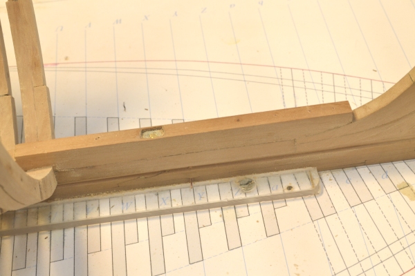
Young America - extreme clipper 1853 Part 21 – Keelson/Forward Deadwood continued American Clipper Note: When Young America was launched in the spring of 1853, her builder, William Webb, incensed by some critical press, issued a challenge to the owners of the fast McKay clipper Sovereign of the Seas to a two-ship, head-to-head race from New York to San Francisco. Excitement and bookmaking activity ran high. Unfortunately Sovereign sailed for China. Major disappointment all around. Work on the forward sections of the keelson and the deadwood continues. The first picture shows the second section of the lower tier of the deadwood being glued to the frames – held in place by pins with wood chocks buffers. Below is a lower view of this from aft. This view shows the pronounced v-shape of the most forward frames and illustrates the issue of securing timber to make the floor members of these. Before these keelson sections could be installed, the insides of the floor and lower futtock timbers had to be faired – at least up the the floor heads. The next picture shows this finish-work more clearly. Apart from the issue of flatness across the centers of the frames, it is difficult to do this work with the keelson in place. The next picture shows anoth piece of the deadwood being fitted over the forward end of the lower keelson. This picture also shows the mounting nut that is about to be covered forever by the upper tier of the keelson. In the next picture the forward section of the upper keelson tier is installed and anoth piece of the deadwood jigsaw puzzle being fitted. In the next picture that piece is being glued in place. Again, the dark discoloration on the wood is from washing off the excess glue. Finally, as shown below, the last piece of the deadwood has been installed. The sun has shown through the window and lightened this picture to help me celebrate the event. In the next part, I will cover the risky task of cutting large scores in both sides of the deadwood to seat the cant frames. Ed


- 3,618 replies
-
- 15
-
-
- young america
- clipper
- (and 1 more)
-
Thanks for the information on the cotton, Bruce. I used cotton for the seizings and serving on Victory, but was concerned about stretching on rope over time and also strength - in hindsight probably overconcerned. I noticed that you prestretch the rope. I used Barbour Irish linen for my made rope. It is virtually fuzz free and very strong. I found that stretching it almost to the breaking point while still in the rope machine was enough to set it. If I decide to rig YA I will give the DMC cotton another look. I used mercerized cotton polyester for lines too small to be spun. I have this theory that the polymer memory in polyester will keep it from sagging. I also use an alcohol lamp to de-fuzz this. What do you do for these small lines? I too used cards for setting up the deadeyes - made from 1/16 hardwood. I used thin wire through two holes in the upper deadeyes twisted at the back to secure them. As I'm sure you have found, this method not only allows the shrouds to be tensioned with the deadeyes aligned, but also makes a convenient holder when making the seizings. Thanks again for the tips. I put a pair of those Lindstrom cutters on my wish list. Ed
-
Excelent, Bruce - and a great explanation. Thanks for the tip on the Lundstrum cutters - worth the price of admission. McKay was sure a belt and suspenders guy - evidently not just in his framing. Working stern to stem will be interesting to follow. The two toughest connections I had to make on Victory were the mizzen stay and the main topmast stay - seized to eyes in the deck behind all the running rigging behind the bases of the forward masts - not fun. What material are you using for your ropemaking? Ed
-
Great. Thanks, Druxey. That will save me trying out a lot of other things. Ed
-
Not a problem, Rob. Its a great picture. Daniel, I do not have a solution for cleaning off epoxy, but I am looking for one, if anyone has a suggestion. Liver of sulfur does not blacken brass in my experience. This is the reason I use copper for metalwork that needs to be blackened after installation - and wherever else I can for that matter. I like LOS better than the blue solution which is generally used for brass. This will stain wood. I avoid using this whenever I can. For iron bolts I ussually use black monofilament, but on bolts to hold iron knees on Naiad I sused copper wire the LOS to blacken. Ed
-
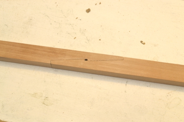
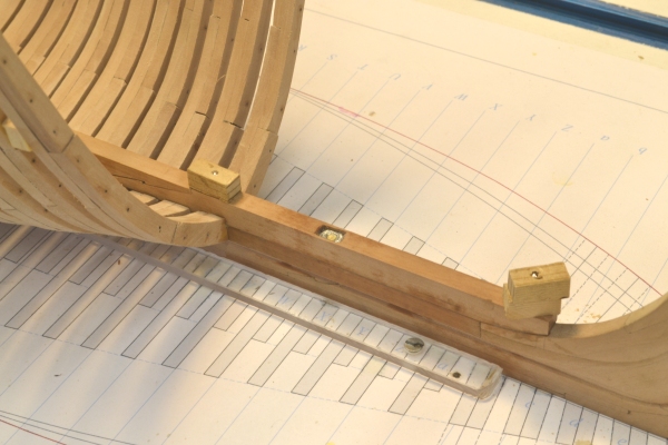
Young America - extreme clipper 1853 Part 20 – Keelson/Forward Deadwood American Clipper Note: In the last part I mentioned Flying Cloud’s record on her 6 passages around Cape Horn from New York to San Francisco before she was retired from that service. These averaged 116 days - 102 days if the last 185 day trip, during which she was dismasted, is discounted. In her long career Young America made the passage 20 times from New York, three times from Liverpool and once from Antwerp, with an average of 118 days per trip – her best from New York being 102 days – her worst, 142 days from Antwerp against persistent headwinds. Her best from Liverpool was 99 days. This was a stunning 30 year performance. So, back to the model. The remaining frames forward consist of half-frames and cant frames that bolt through the keelson and deadwood. Since the keelson is bolted atop the square frames, they must be installed first. So, with all of the forward square frames installed, the forward part of the keelson and the forward deadwood can be constructed. In the last part I showed a picture with two strips representing the two tiers of the keelson. The forward section of the lower tier – the keelson proper – houses the forward model mounting bolt. In the first picture a 4-40 nut has been filed down to fit a mortise in the keelson and is being epoxied in place. The next picture shows the mounting bolt screwed up through the keel, filler and into the nut in the keelson. It is protected from screwing in further by of the larger diameter shoulder butting against the bottom of the keel. The above picture was taken after installing the first section of the keelson. Before that could be done it had to be fitted to the apron at its forward end. At its aft end there is a large scarph joint with the next segment. Both halves of this joint were made before setting the forward segment. The joint is shown below. In all keel and keelson joints the face of the joint slanted downward in the aft direction. This is one good reason for installing the keelson from fore to aft. The next picture shows the lower keelson being glued over the filler and the forward square frames. The picture shows the joint with the second lower segment, but that piece is still loose in the picture. The wet spots are from washing off excess glue. The installed piece was then “bolted” down into the keel with copper wire bolts. That process is described below. The bolts have been filed off flush in the next picture. The next picture shows the first section of the forward deadwood being fitted. The pattern is still attached. The keelson and the deadwood is sided the same as the keel – 16”. The last picture shows the insertion of the copper bolts to secure the piece of deadwood. This piece has already been glued in, but the process being used for the bolts will also add strength to the model joint. First holes are drilled at a size that will allow a slip fit for the 22-gauge wire being used. This wire is pre-stretched to stress harden it. The holes in this case are about 1” deep, so the bolts are about a scale 6 feet long. The bolts are dipped in 5-minute epoxy and pushed into the hole. They are then moved in and out, removed and dipped in epoxy again, reinserted and again moved in and out. This distributes epoxy throughout the hole. These bolts will not come out. When the epoxy hardens the bolts are clipped and filed off flush. As additional members are added, they are bolted in a similar way with bolts as long as my drill bits permit. Later, additional bolts will be driven like this, through the forward part of the stem into the apron and deadwood. The keelson bolts are installed in like manner. In the next part, the forward upper tier of the keelson and the remaining forward deadwood will be constructed. Ed


- 3,618 replies
-
- 15
-
-
- young america
- clipper
- (and 1 more)
-
Walt, this iron lattice-work extended only from the floor heads up to the planksheer. Also, the iron used was ductile enough to be cold formed either over the outer frames or into the concave inboard frames. In both cases these were scored so the plates would lie flush with the face of the frame. They were then bolted through the frames and through each other at the intersections. Hope this helps clarify. Ed
-
ancre LE BONHOMME RICHARD by Jeronimo - FINISHED
EdT replied to Jeronimo's topic in - Build logs for subjects built 1751 - 1800
Extraordinary work as always, Karl. Ed- 662 replies
-
- 1
-
-
- bonhomme richard
- frigate
- (and 1 more)
-
Not wood. 3/4" X 4" iron plate.
-
Well, the mystery of the strapping continues. Rob, I am familiar with the Campbell drawings and have read the book. I don't think it is conclusive either way. John, I do think the secondary sources have not made a case either way - probably because there is no real data. To me, the best argument - until I learn something new - is that in 1856 Webb built the very large Ocean Monarch and it was internally strapped. To avoid suggestions of sources already consulted (and to provide a sort of bibliography for anyone interested) I list the sources used so far on this and other construction: Crothers, The American Clipper Ship Howe and Matthews, American Clipper Ships MacGregor, Fast Saling Ships Chapelle, History of American Sailing Ships and Search for Speed Under Sail Campbell, China Tea Clippers Desmond, Wooden Ship Building L. McKay, Practical Shipbuilder New York Marine Register, 1857 American Lloyds Registry 1859 Maclean, Boston Daily Atlas - Challenge 1851 Clark, The Clipper Ship Era Cutler, Greyhounds of the Sea Underhill, Masting and Rigging SeaGull Plans (Crothers) for Lightning, Challenge, Young America Suggestions of other sources are of course welcome. Thanks for the input on this. Ed Bruce, I have not read the book but ordered it used from Amazon for $4.
- 3,618 replies
-
- 1
-
-
- young america
- clipper
- (and 1 more)
-
Hi Allan, No, the ends are not shiny when they are shaved off with the blade. They usually also get sanded - or filed - with no ill effect - unlike blackened metal. They are mostly for appearance. Its hard to get enough CA into the hole to gain much holding power. There is no reason for pigment over acrylic paint, except that I did not want to risk corrupting the glue with the acrylic emulsion. I felt safer with the pigment. But from your comment that appears not to be a problem. Paint is certainly more readily available and based on what you said I would not hesitate to use it. I assume you dilute it to get good mixing with the glue? Thanks. Ed.
- 3,618 replies
-
- 2
-
-
- young america
- clipper
- (and 1 more)
-
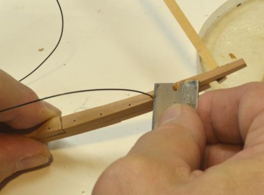
Young America - extreme clipper 1853 Part 19 – Framing Continued American Clipper Note: On her fourth voyage, still under Cressy, Flying Cloud left New York for San Francisco in January 1854 and set a new record of 89 days, 8 hours, just under her 1851 performance. This record would eventually fall to Andrew Jackson in 1859 with a passage of 89 days, 4 hours. This new record would be in dispute for years. These matters were taken quite seriously. Given the vagaries of wind, weather and seasonal variations, one wonders what all this recordkeeping really means. Between 1851 and her last Cape Horn voyage in 1856 Flying Cloud's record to San Francisco included passages of 89, 113, 106, 89, 112 and 185 days. I am getting close to wrapping up the forward square frames. The remainder of these frames – P through U are shown below after beveling as described earlier. The narrowing of the lower hull forward can clearly be seen. The next picture shows the frames with cross-spales being fitted to U and P. The next step was to reduce the sidings of the upper futtocks and toptimbers. This was described earlier. The last step before erection is to install the framebolts. These were 1” iron, unheaded, cut off flush. They are simulated with 30 lb. test black monofilament. After dipping in CA the filament is slipped through the pin holes used for assembly. There were 3 to 4 of these bolts per timber. There are two through the rail stanchions as shown above. After gluing in, the excess ends are easily sliced off with a razor blade as shown below. The next picture shows the remaining forward square frames installed. Starting with frame R going forward the sidings are reduced and the frame spacing increased. For example the floors go from 14” to 12” and the frame spacing from 32” to 34”. Webb used this method to reduce hogging by lightening the forward structure where the hull buoyancy was less due to the fine entry. This design feature was able to reduce the weight of the forward structure by as much as 25 tons in Webb's ships. On the model the spacers have suddenly gotten larger due to the increased separation. The last two are being fitted above. Next, another picture of the framing at this stage. The next picture shows the connection of the last frame, Q, at the keel. There are two points of interest here. First, there is the filler on the keel forward of the last full frame. Frames forward of this one will bolt to the sides of this filler and the keelson/deadwood – soon to be added. Second, notches in the tops of the frames at the keel can be seen. This is to provide additional bolting height for the next few frames which would otherwise have to be bolted only at the lower 17” of their feet – not enough – in my opinion. Additional bolting space can only be added by raising the cutting down line aft of this first half frame. If this were done suddenly at frame V there would be a step up in the inboard planking, so to provide a fair bed for the planks, I started raising the cutting down line four frames aft, adding additional bolting height of about 7" for the first half-frame. The last picture - showing some strips representing the two tiers of the keelson - will help illustrate the above issue and also show the huge size of the keelson. These two 16”w x 24”h tiers ran in a straight line from stem to sternpost, bolted heavily through the frame floors to the keel. I have placed a pencil mark on the lower keelson to show the raised cutting down height. This additional height will allow one of the horizontal bolts for the first half frame to be driven through the lower keelson. The model mounting bolt and nut is about to be set into the actual lower keelson once the forward end of that that is fitted to the apron and marked for length. Ed

- 3,618 replies
-
- 13
-
-
- young america
- clipper
- (and 1 more)