HOLIDAY DONATION DRIVE - SUPPORT MSW - DO YOUR PART TO KEEP THIS GREAT FORUM GOING! (Only 13 donations so far - C'mon guys!)
×


EdT
-
Posts
2,214 -
Joined
-
Last visited
Content Type
Profiles
Forums
Gallery
Events
Everything posted by EdT
-
Toni, The original shipwrights had the same problem fitting beams into place - even without the knees. Their end clearances were very close and the frames above the decks "tumbled home." I suggest you do what they did if you can - spring the beam by lifting the center while holding the ends down, then rotate it into place. I installed Naiad's beams with knees attached using this method. Thanks to Blaise Olivier's 1737 commentary on English practice. (The French at the time apparently set the beams then raised the clamps under them.) Here's a picture. Ed
-
Hello Alan, Thanks for responding to my post. Please do not feel that you need to respond to these comments. I made my peace with all these issues long ago and only offer comments that I think may be helpful. I am glad to do that - for what they are worth. I suggest you give some thought to the frame bevelling before lofting patterns. I believe many modelers leave the bevels to the sandpaper, but keep in mind that the frames need to be bevelled inside and out. Patterns need to account for this. Patterns from reliable draftsman do that in a way to enable the bevels to be sanded inside and out with enough wood left to meet the molded thickness requirements of the frame when your finished sanding. Also, keep in mind that at the forward and aft ends, bevels become quite extreme and require installation of very thick frames if unbevelled. Cant frame bevels are a story in themselves. Some modelers partially pre-bevel - if the patterns show the bevels. I did this for Naiad where all four profiles for every frame were lofted. On Young America patterns also included all four profiles and with the assembly process used - enabled by the CAD lofting method - left patterns on both fore and aft faces of every frame pair after assembly. This enabled the frames to be completely bevelled before erection - as was done in he shipyard. I am not sure if anyone is doing this besides me but I would not go back. Why do this pre-bevelling? Sanding/paring inside the hull is a pain. Erection of bevelled frames is much easier. It is also more accurate. You can check the hull fairness as the frames are erected. There are many ways to skin this cat. I only offer this as food for thought. I'm not in the persuasion business. Have fun - and good luch with the project. Ed
-
Mark, I found that to get a uniform glue line, especially in curved fayed pieces,that the fit has to be almost perfect and the clamping pressure moderate. At best it will be a fine line. More pigment in theglue may help. Be sure to coat the edges liberally with glue so it squeezes out all along the line when clamped. The alternative if you want a very pronounced uiform line is,s you porbably know, to use paper at the expense of joint strength. I am told that black tissue absorbs glue and adds strength, but I have not tried it. The latex paint that I use on planking would be a bit messy and time consuming on all these structural parts and it also leaves a weak joint. Copper wire bolts with epoxy can overcome the joint strength problems if you go the paper/paint route. Its always a journey. Ed
-
Yes, Alan, the plates would be a big help, but I guess you get what you pay for -and this is a wonderful freebie. Digesting this can be a challenge - make frequent use of he dictionary at the front - and again, good luck. It is a journey. Ed
-
Alan, I think you will find the Vade Mecum very helpful. It may take some time to digest, but it will be well spent. It took me some weeks and some things did not sink in for months. I would draw your attention to some specifics: p 144 begins the section on making drafts. p 162 begins the specifics of drawing the sheer plan - which should be done first - in 2D at least - I can't comment on 3D - as with the original guys, I don't use it. P 195 explains the diagonals. You have not mentioned these. They are quite important - for setting frame joints, fairing lines and drawing the body lines. p.255 begins the section on tables for forming the bodies and describes important lines that are used to make the draft. Scantlings begin on p 266. The glossary is also very useful and sometimes very import points are mentioned only there. I caught up with your log late, but just a few observations: I note that you are taking dimensions from the bottom of the keel. It was/is normal practice to use the top of the keel as the primary dimensional reference line. Some dimensions in tables will be on that basis, but it is otherwise just a matter of convention. You have not mentioned "room and space". This is the distance between frame lines. 2X room and space is the distance beweeen "stations" - main frame lines on the draft. Room and space allows room for two frames plus air space between the floors. There are then 4 frames for every station. Room and space also sets the gunport width since the ports are framed main timbers. If you are planning to loft individual frames you should consider how these will be defined. You may find, as I did, that at least the intermediate frame profiles are needed and perhaps some in between to accurately define frame bevels - the ones Allan mentioned. You mentioned dimensional error between views on the drafts but did not say how much. I checked the original Naiad drafts - before using them - for accuracy using the scale at the bottom and some other points on the drawing and found them to be 99.8 to 99.9% accurate. These were paper copies. From my experience scanning often induces distortion and I would not be surpised to find digitized versions to be less accurate. However, what is important is to decide what tolerances you will set for your drawings and then decide whether dimensional variation on the drafts is material or not based on that. For example if the moulded half-breadth of your ship is 20', how much deviation would you accept on the model - 1/32"? 1/64"? at 1:48 these equate to .63% and .31% respectively - for dimensions like that. For timber thickness, if you work to say .005" on a 12" timber (at 1:48) that equates to a tolerance of about 2% on dimensions of that type. From this you can determine acceptable drawing error. I think 1 to 2% is generally quite reasonable for model work. Waterlines on these ships are not often keel-parallel and - as druxey says - you must build on a surface parallel to the keel to be able to set frames vertically. Actually, except for fairing, waterlines on these ships were not very useful. Diagonals were much more useful even for fairing - and certainly more accurate for plotting hull profiles. I found it convenient to define separate keel-parallel waterlines and draw those from the body plan on the half-breadth. I then used those for whatever purpose needed - for example templates to check the hull - those are best set up parallel to the board surface. There are a lot of lines on the original drafts and some may be mysterious. All are important. I would make sure to understand what each one is. The Vade Mecum will help with that. I hope these few points will be helpful. You are just beginning a major and very complex effort. All the best with it. Ed
-
Alan, I am not sure what Steel pdf book you are referring to. the source you need is Steel's Naval Architecture, not the treatise on masting and rigging. I was not aware the Steel's Naval Architecture was available for download online. If it is, could you please provide the link. There are other sources for scantlings - the sizes of the timbers. In addition to Steel, there is The Shipbuilders Repository 1788. Both this and Steel are fairly rare and quite expensive. There is also Steel's Vade Mecum for the Shipbuilder which can be downloaded online. This not only has scantlings for a 74-gun ship, but also has instructions on preparing drafts. I would highly recommend reading these before you get too far with this. The Vade Mecum can be found at this link. http://books.google.com/books?output=acs_help&id=pjcDAAAAQAAJ Another source of dimensions is the original ship's contract which may be available from NMM. This document is also highly recommended if you are going to do your own plans. If the contract for Bellerophon is not available, one for one of the other Arrogant class should be identical. Ed
-
Thanks, Mark. I feel the same way about your work. Sailor, I don't think the model strapping is adding any strength to the hull. With the frames secured only at the keel and at the ribband at the top, they were subject to a lot of movement when sanding etc. With the added wood members - the clamps and the bilge ceiling - this has been eliminated on that side and to some extent on both sides. Fore and aft frame movement is, of course, completely eliminated with all these longitudinal members. It is also much harder to deflect the hull shape along the top as well. There's nothing too surprising in this, but I am just glad to be through that stage when it is easier to cause damage - especially when the hull has to be inverted. Sorry if I mislead you on the strapping. I'd say on the model its purely ornamental. Ed
-
Thank you for these comments and for all the "likes". Yes the iron strapping was an anti-hogging measure. There were others - the heavy band of bilge ceiling, weight reduction at the ends of the ship by increasing spacing between frames and use of smaller timbers, massive keelsons, setting the foremast further aft, etc. Hogging was certainly agravated by swells passing under the ship but a more fundemental cause was the very narrow lines at the bow and stern. This greatly reduced the flotation area of the hull at these ends and this put constant stress on the ends - even without waves. The long fine-lined clippers were more susceptable to this than many other types. The problem was never completely overcome in wooden ships. Ed
- 3,618 replies
-
- 1
-

-
- young america
- clipper
- (and 1 more)
-
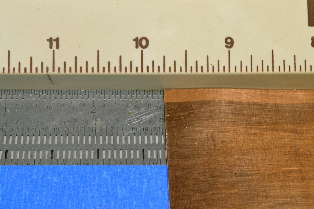
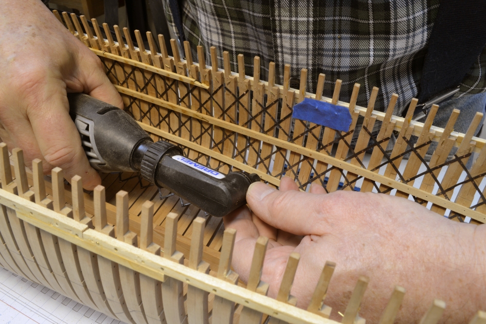
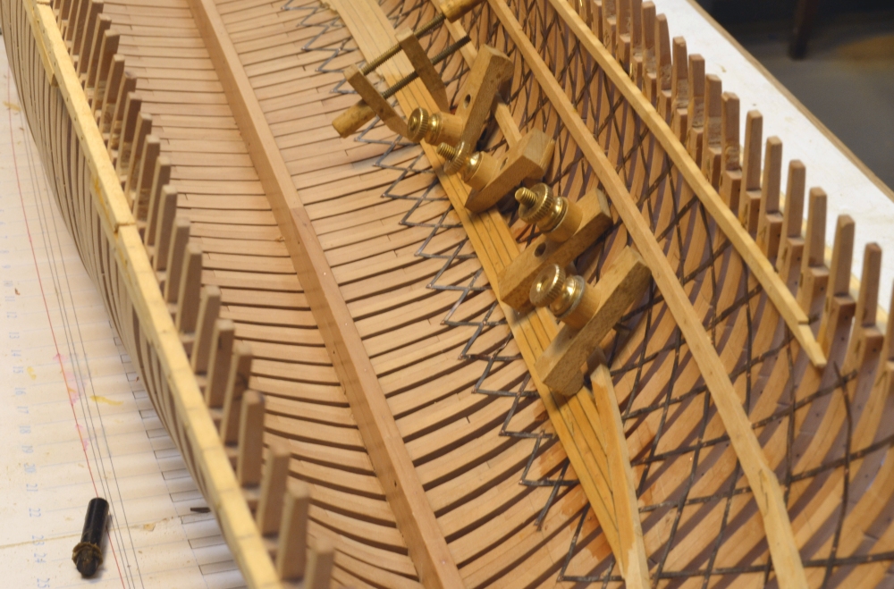
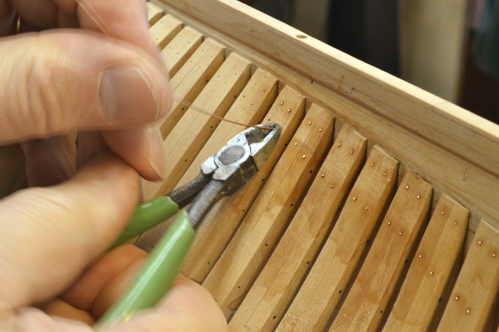
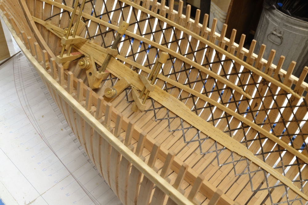
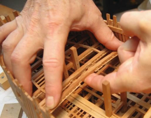
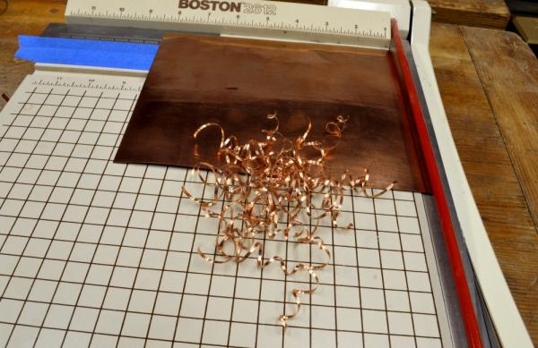
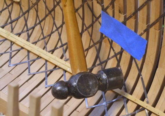
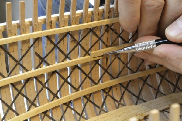
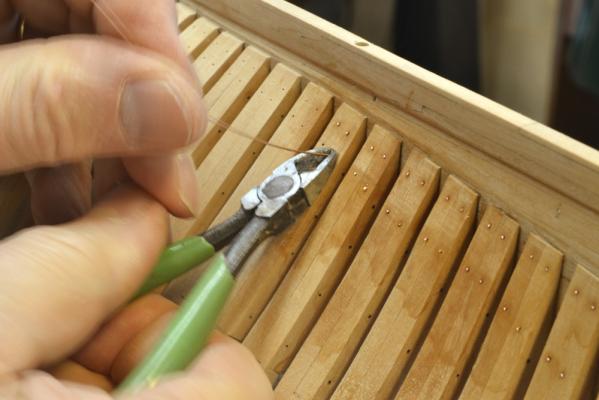
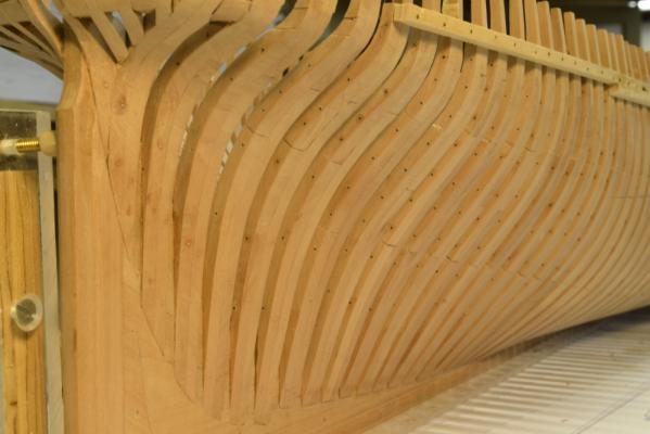
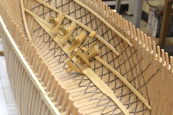
Young America - extreme clipper 1853 Part 46 –Inboard structural members continued Work on the starboard side, inside of the hull, continued. The iron strapping on that side is complete, except for a bit of repair work. The first picture shows the use of an Incra rule taped to the paper cutter to assist in cutting the straps to accurate widths. The sheet is first squared up on the cutter and then advanced 1/16” after each cut. The indexing holes on the rule could be used, but I found this unnecessary and rely on my eye. Below is a picture of strips after slitting on the cutter. Fortunately, these straighten out easily and quickly when held in a vise and pulled with pliers. After that they are blackened with LOS before installing. They are held in place with copper “riveted bolts” made from 22-gauge copper wire. These are more like nails, being pushed into a tight hole, then clipped off, then peened over with a small hammer – as shown below. Once the strapping was finished, the deck clamps on this side could be installed back to the stern. The next picture shows a scarph joint being marked on the next piece. Initially I fitted the next of these joints on the bench, but identifying them and keeping track became more trouble than doing it in situ – with equivalent results. The next picture shows the right angle Dremel drill boring holes for the through bolts. I don’t use this tool much. It is large and has a good kick when starting, but it is indispensable for drilling “normal” bolt holes down in the hull. I use it with a Foredom foot pedal speed control, plus the speed contol on the tool to keep the speeds low and to avoid it jumping out of the center-mark. The 22-gauge copper wire used for the bolts is a sliding fit in the holes. An end is dipped in epoxy and pushed through the holes. The outside is then touched with epoxy and the wire pulled back in. These bolts are never coming out. They will be sanded off flush and those that are visible will be blackened later. Many on this side will be covered with planking. Fastening the deck clamps is pretty easy work, but the 8 x 8 ceiling members at the turn of the bilge are another matter. The curve of the hull where they are placed can be seen in the next picture. These require some serious clamping and long waits for the glue to set. I usually bolt them in place with the epoxy wherever possible before removing the clamps. I am being extra cautious – as well as authentic – in the bolting through every frame because of the copper plates between the frames and the inboard members. I don’t trust the glue alone on these joints. The hull is now becoming extremely rigid. The last picture shows a strake of bilge ceiling being attached toward the stern – intersecting with the lower deck clamp. This picture also shows the strapping toward the stern. Not too much of it is damaged. I straighten our any problems as each wood member is added. Most of the strapping on this side will only be visible from outside the hull – through the frames. And so it goes… Ed


- 3,618 replies
-
- 21
-
-
- young america
- clipper
- (and 1 more)
-
Thank you William. I hope you will like the books. Be sure to check out the links below to the book topics on this site. Any addenda and corrections are/will be posted there as well as some other useful information. Ed
-
I like your test panels, Mark. Tthey are always worth the effort. I have moved to using dark brown acrylic latex paint between the edges of planking. This method is only practical if you can paint one side of flat stock before ripping off the planks, but it gives a very even line - almost like using dark paper. You can always add coats to make more of a caulk line or use lighter brown to make the lines more subtle. However, I have also used a ton of darkened glue and still do. Cheers, Ed
-
HMS Naiad 1797 by albert - FINISHED - 1/48
EdT replied to albert's topic in - Build logs for subjects built 1751 - 1800
Lovely work Albert ....and the neatness of your workspace is almost surreal. Please tell me you tidy it up for the pictures. i would be intimidated by all the order. I love the ribbands you are using to set the central frames. I wish I had thought of this earlier. It has been a great help in setting the frames on Young america. Very impressive work. Ed -
As with many things, David.
-
Being at "the cutting edge" at 20 knots would certainly do in any nefarious plans of pirates. Of course pirates would have to place themselves directly in the path. I don't think these focused clipper captains would be inclined to alter course - a the cost of a minute or two. I am giving the viewports quite a lot of thought and the plan is still evolving. I am thinking that they would extend from he middle deck clamps down to the floor heads on the unplanked port side - leaving the lower deck framing and clamps intact. Perhaps three frames pairs on either side of the partners of each mast would be removed. I need to decide this soon before I start ceiling planking and strapping on that side. They may need to be wider,but I do not want to weaken he hull too much. Hwever, the epoxy bolting of the bilge ceiling and deck clamps plus inboard planking above the middle deck should make th hull quite strong. Ed
-
Gary, if you have printed any patterns at 106%, I suggest you discard them. This difference is more than enough to give you untold headaches if they are used. I am an advocate of the "just-in-time" approach in most modeling steps, so I print only the patterns I need at any particular time, and cut out only the pieces needed for the next step. I highly recommend this approach. It has many advantages. Ed
-
Thank you very much, Doris. You are very kind. I admire the artistry of your work very much, so your comments are well appreciated. I am glad to see your work getting the attention of readers on this site that it deserves. Ed
-
Alex, I have just caught up with your log and read through it for the first time. Your work is as close to perfection as I have seen. Beautiful. Ed
-
Nils, I have just read through your Pamir build log for the fist time. Beautiful work on a beautiful ship. The metalworking is exceptional. Obviously the pictures are a mixture of "in-progress" and the finshed model. I look forward to seeing your work on the metal plating and many other things. Congratulations on a very fine model. Ed
-
Gary, the 6 1/2" dimensional on p.45, col 1, para 4 is is typographical error. I am aware of this and probably should have included it in one of the Addenda. I have it on my list in case their is a second printing. In general always use the drawings, drawings notes and other sheets as primary sources for dimensions. Sorry about the typo. I am pretty sure that the printing scale is set by your pdf print settings and not by the pattern sheet itself. In any event, they should always be printed at 100% or actual size. Pdf print settings sometimes default to "fit to page" or the previously printed scale. I put some printing instructions in Addenda 2. Here is the link http://modelshipworld.com/index.php?/topic/248-the-naiad-frigate-by-ed-tosti/page-2 If you have not already done so I suggest going through my posts on the Naiad Frigate Volume I topic and printing off all of the Addenda. Some are corrections, some provide other information. That topic is where I post anything relating to the book. It is also the topic where most readers questions or comments are posted. There is a link to the topics for both volumes at the bottom of this posting. Also, if you find any other glitches, please post them there. Ed
-
Thank you all for the comments and the "likes". Yes, Greg, both sides. The port side will be left in open frame a la Naiad. The starboard side will be planked down a bit below the waterline. I am considering leaving some rectangular viewports below the middle deck down to the floorheads on the port side. So the strapping will be visible in unplanked areas through those openings and from the outside on all unplanked areas. I don't like repetition but the biggest problem with the strapping work is leaning over the hull. Nils, a number of American clippers including Young America were strapped so it is authentic. The bracing was one of many anti-hogging measures used in these ships, which because of their great length and sharp lines was a considerable problem. This was , of course, a merchant ship, so battle was not an issue - except perhaps for pirates. I expect YA could outrun most of those without difficulty. Ed
- 3,618 replies
-
- 1
-
-
- young america
- clipper
- (and 1 more)
-
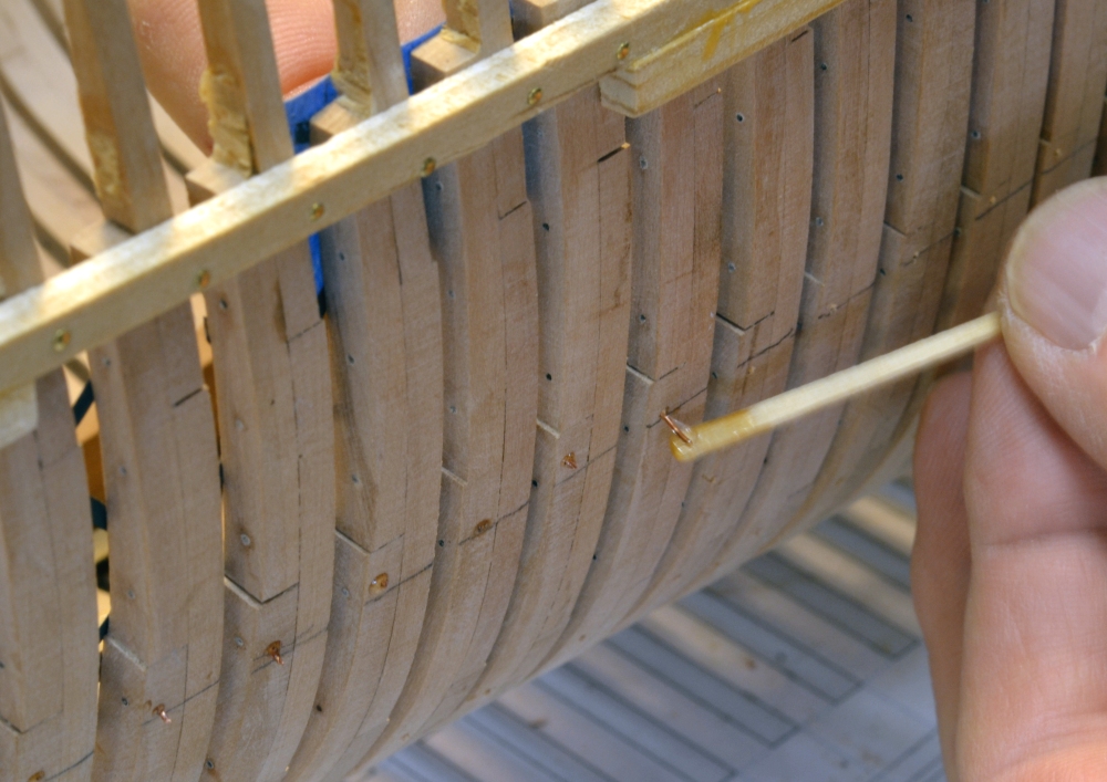
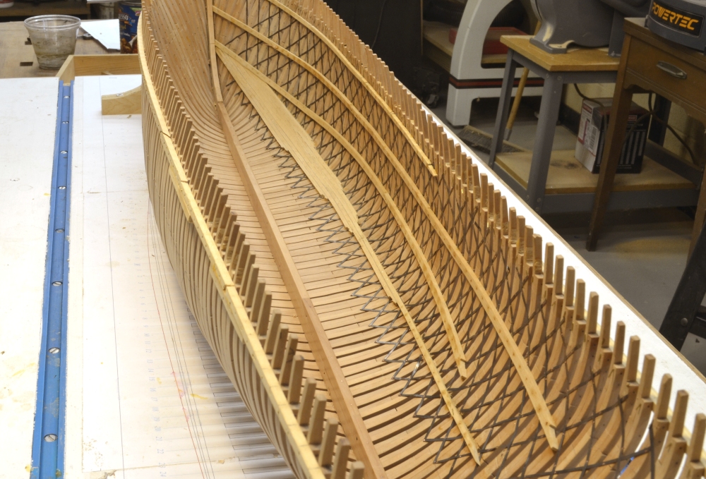
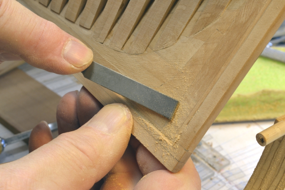
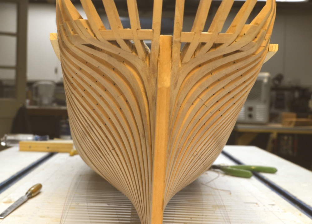
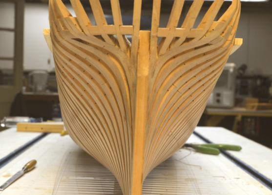
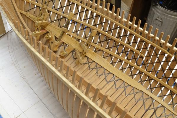
Young America - extreme clipper 1853 Part 45 –Inboard members continued, Stern fairing and half-frame bolting continued. American Clipper Historical Note: In 19th Century America, forest resources were plentiful, in fact they seemed limitless. For these reasons, and due to the immaturity of the American iron industry, ships with wood structures continued to be built throughout the century and into the 20th. Several domestic species found their way into American-built ships. White oak, very similar in species to English oak was the primary material used for structural components. However, the less plentiful but superior species, live oak from forests in the southeastern states, was often specified for critical components. It was almost 50% stronger than white oak and the shape of the growth lent itself to knees and curved members. Joshua Humphreys specified live oak for the original American 44-gun frigates and crews from the northern shipyards went south to harvest the requirements. Another southern species that was widely used in American ships was hard pine, also known as longleaf pine. This plentiful timber had 90% of the strength of white oak and was roughly the same weight. Hard pine was used for beams, planking and knees. White pine, the species most associated with the term “pine,” was lighter, softer and less strong – only about 50% in strength compared to white oak. It was often used in planking weather decks. Other species of pine – pitch pine, yellow pine, red pine – were also used. Another important species was black locust. Its hardness, straightness and strength – 35% stronger than white oak - found wide use for treenails and often for pillars. Various other structural woods were used, but these were the primary species. Young America’s structure was largely white oak – most frames, central sections of the keel and keelson, stem, stern posts, hanging knees. But it is very probable that a significant number of important members were of live oak – parts of keel and keelson, keelson riders, hooks, some frame timbers. Hard pine was used for beams, inboard and outboard planking, waterways, deck clamps, binding strakes, lower deck planking and deadwood. Lodging knees would have been pitch pine. Exposed decks were white pine. Pillars and treenails were locust. Other decorative works were of other species and will be described later. For the model, I an using Swiss pear wherever oak – white or live – was used. Hard and pitch pine members will be Castelo. Weather decks may be holly – not decided. Most of the work covered so far has been in pear, but Castelo has been evident in the last few posts in the bilge ceiling and deck clamp construction. Work described in the last part continued. In the first picture the deadwood near the sternpost is being smoothed with a #0 cut Grobet riffler after paring with gouges. When the fairing of the aft part of the lower hull was finished, the bolts securing the aft half and cant frames were installed. The next picture shows this in progress. Holes were drilled deep into the keelson/deadwood. Copper wire dipped in epoxy was then inserted and moved in and out to distribute the glue internally. The wire was then clipped off as shown. The stains on the wood in the picture are from isopropanol used to wash off excess epoxy and has not yet dried. The heads of the bolts will be sanded off flush and blackened just before the final wood finish is applied. They were iron. The next picture shows the lower hull after this bolting. Bolts will be much more visible when black. Finish sanding and polishing of these areas will be done later. The next picture shows the stern framing from directly aft. Work inside the hull on the strapping, deck clamps and bilge ceiling continued. In the next picture a strake is being glued on the upper side of the band. Strapping below the bilge ceiling has been added. One of the lower strakes is being glued in the next picture. After the glue has dried, all of these strakes are bolted through every frame with epoxy at both ends of each bolt. These bolts, also iron, will be blackened later. This internal work is going to take some time. I switch between iron strapping and ceiling planks when I can - to battle the tedium of repetitive work – not my strong suit. Ed

- 3,618 replies
-
- 31
-
-
- young america
- clipper
- (and 1 more)
-
Hello, Gary. I think of the rising wood, or "hogg" as it is sometimes called, as the part of the deadwood in the central part of the ship where it supports the full frames - frames 24 to O. On Naiad, this member is the same breadth as the deadwood (18 1/2") and in the central part of the hull, from frame line O back to the aft face of frame pair 20, it is 8 1/2" (not 6 1/2") deep. On Drawing 4 the top of the rising wood shows as a straight solid line 8 1/2" above the top of keel between the above points. The size of this central part of the rising wood is also given on the notes sheet for drawing 4 on the CD. Beyond this long straight section the deadwood rises in height. The correct heights can also be seen as the height of the notch on every frame pattern. Full frames aft of this - 21 to 24 - have deeper notches to accomodate the higher line of what could also be called the rising wood (or the deadwood). In the area of frame 21 the rising wood transitions to the members of the aft deadwood. See the Stem/Apron pattern sheet and the Deadwood Sternpost pattern sheets on the CD for addtional detail. They show the pieces of the deadwood that abut the 8 1/2" straight rising wood at each end. I hope this helps. Ed