EdT
-
Posts
2,214 -
Joined
-
Last visited
Content Type
Profiles
Forums
Gallery
Events
Everything posted by EdT
-
Thanks, everyone. Allan, I owe a lot to the exhaustive research of William Crothers. Without his book this project could not be done - at least not without years of independent research. Most of these details are easy to add - once you know about them. The arrangement of the drainage limbers on these ships can only be understood when you realize that they employed suction pumps, so the suction point could extend all the way to the outer planks without chopping out whole timbers. This also avoided the need to "pack" the spaces between the floors as was needed with the chain type pumps of the 18th C that could only reach down to the floors. Very interesting detail - too good to leave out. Ed
-
Good discussion. I can't offer much help, I'm afraid. I went through similar issues with Naiad - different ship, different arrangement. The only way I could see of framing the helm port was with wood chocks between the transoms cut with the rudder hole. Not much help in this case, but I did have two other observations. From the contracts I have read, the only transom with a rabbet was the one on the exposed deck. I believe the purpose of this was to enable a caulking joint at the ends of the deck planks. This would not be necessary on lower decks. Setting the deck and seat transoms after installing the counter timbers was perhaps the most difficult task in building Naiad. I found it very difficult to cut scores that matched the inward and aft slanted lines of the tmbers. I suspect that in practice the transoms were installed first. String lines could then be used to mark the lines of the counter timbers on the transoms for scoring. I believe if I were doing this again I would use that approach. Anyway, these are just a couple of related thoughts. I love your thoughtful, thorough and precise approach, Mark - and where would we be without Gary's detailed research? Ed
-
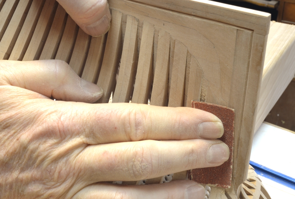
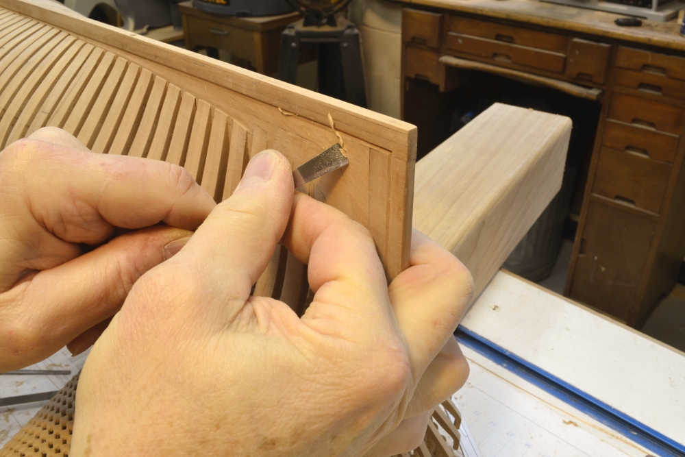
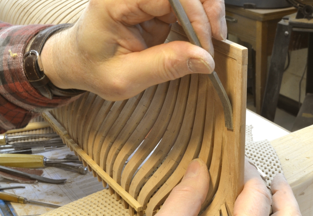
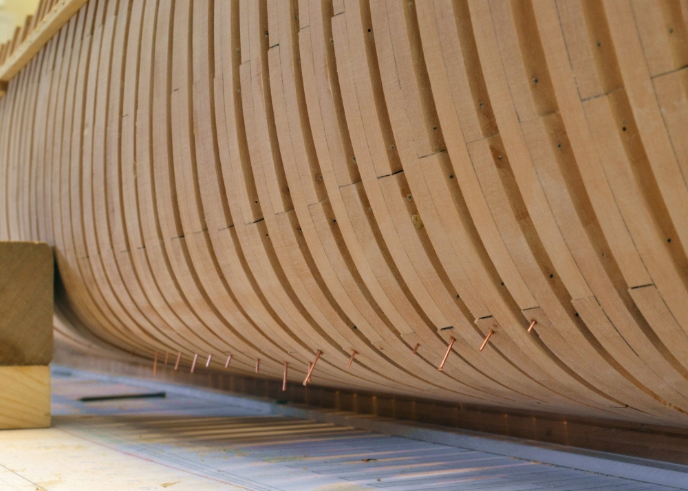
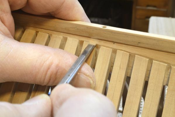
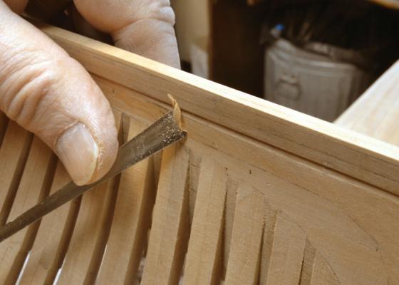
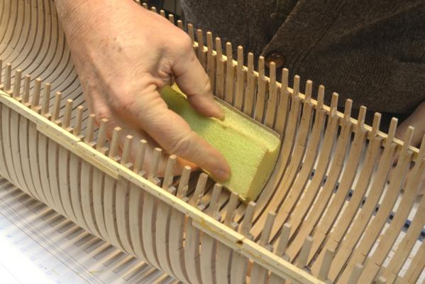
Young America - extreme clipper 1853 Part 44 –Inboard members continued, Stern fairing and half-frame bolting. Work continued on the iron strapping with some breaks to work on other things. Other things included installing wood members over the strapped areas. In the first picture a portion of the lower deck clamp is being glued to the frames. The forward section of the upper deck clamp has been installed at the top of the strapped area. As soon as the clamps are removed when the glue has dried, these members are immediately bolted through the frames with copper wire bolts epoxied all the way through the hole, making an extremely strong connection. In the next picture a section of bilge ceiling is being installed. These heavy members will fill the area up to the lower deck clamp. There will also be a few strakes of bilge ceiling below the installed strakes. The iron strapping will also be extended down to the floor heads. The next picture shows one of these extensions. The break in these straps will occur behind frames and will not be visible. The next picture shows additional deck clamp sections installed, including forward sections of the middle deck clamp. All these members are epoxy bolted as described above. Before progressing much further aft with the iron strapping, I wanted to get the aft half-frames bolted securely. They have been held in place since installation only by the end-grain glue joints. I did not want to risk breaking these with the hammering of the strap rivets. Before installing bolts on these frames they needed to be faired. This is easier before the copper bolts are in place. In the next picture 80-grit sandpaper is being used on the feet of the cant frames to bring them flush with the deadwood. In the next picture all of the cant and half frames have been faired at their feet. The cant frames, in their scores, end right at the bearding line line. However, the half-frames are not installed in scores but bolted directly to the deadwood. These were not faired to a feather edge at the line but were cut back to about a 3” thickness above the line. The triangular gap was covered with planking. It acted as a limber, or drainage channel, for water that would otherwise accumulate between frames and in the joints between the frames and the deadwood. This feature was evidently not included at the feet of the cant frames. The next picture shows the feet of the half-frames being squared off above the bearding line. There will be more to say later about the path of this water to the pumps. With the model inverted it was a good time to fair the deadwood back to the rabbets in the keel and sternpost. The next picture shows a shallow gouge being used to rough out the shape above the keel rabbet. This can be risky if not done carefully. In the picture the curl of shaving shows that the gouge is moving parallel to the keel using the pressure of my thumb. I find that cuts go easier at an angle to the edge, slicing the wood - and it is never a good idea to cut toward the rabbet. The gouge is moving in the same direction in the next picture – held as in the last picture with the left hand, in this case pulled gently with the right – always with very light cuts. Do not attempt this with a dull tool. In the next picture a #0 cut riffler is being used to smooth out the gouge marks. This was followed by 120 then 220-grit paper. The last picture shows the feet of the half and cant frames after the sanding. With the final lines of the frame bottoms established the bolt holes were laid out and drilled. These are now ready for the bolts. There is a lot more sanding to be done on the lower hull, but this much was sufficient to get the bolts in. Now for the other side. Ed


- 3,618 replies
-
- 23
-

-
- young america
- clipper
- (and 1 more)
-
A couple more suggestions for free/cheap wood sources: Old (or even new) tool handles - hammers, axes, garden tools. Usually ash, maple, beech, hickory, sometimes oak or birch. Old wood baseball bats - ash, hickory or hard maple. I recall that many of the treenails on my Victory model came from a broken hickory axe handle. I am pretty sure my clamps came from an old maple drawer front. Occasionally, but rarely, some usable wood turns up in a load of firewood - in our area, cherry, elm, oak - may need a year or two to dry out. Of course some work is required to turn these pieces into usable material - and tools - at least a hand plane and a circular saw. I admit to being thrifty (perhaps even cheap) in buying wood, but there is some satisfaction salvaging really good wood from junk. If youre on a shipmodelling budget, I can suggest better ways to spend money. Ed
-
I do not think basswood is strong enough. Any hardwood would be better. I used maple and have used some Castello as well. Maple, cherry, beech, pear, oak would all be good. You can probably get a piece of oak or maple at Home Depot - if you can rip it into strips. An old piece of maple furniture from a yard sale or junkyard is a perfect cheap source - well dried hardwood - will yield a lifetime supply of tool parts (or model parts). I wouldn't go overboard on rare woods. Once these get used they get dirtied up with glue - especially darkened glue. Ed
-
Mark, the paper cutter is not ideal for a few reasons, but it has some advantages also. It is fast and, there are no rough edges, you can cut length up to 12", thicknesses to /032" or so and it cuts in a straight line. The copper straps on Young America are 1/16" wide, .005" thick.When they are sheared off, they curl up. This is easily fixed by stretching them with pliers with one end in the vise - as is done with the copper wire before bolting - but not too much or they will lose width and thickness. I start with a roughly 6" X 12" sheet so I can use the long edge on the cutter fence to get square cuts. If the table on the cutter is slippery, you might try taping a sheet of paper to it. To get accurate 1/16" widths I tape an Incra rule to the table against the fence. The sheet can be advanced in 1/16" increments by eye or using a pin in the Incra indexing holes. I get several strips per minute - a few more minutes for straightening them. A metal shear would be better. Ed
-
I am familiar with the video. It is very good. I do use the gel. However, whether using the gel or the chips, the solution once made up is about the same life. My can of chips has been around for a few years and it still works. The chips are in a plastic bag in a half-pint paint can which I keep tightly sealed. I use the two types interchangeably with equal results. I do not make up as much solution as she uses in the video - just a few drops unless I want to dip something. I usually brush it on the small metal parts if they are already installed. I usually do not neutralize because in most cases I want it to go all the way to black, but I do usually rinse it off - a little baking soda in the rinse would probably be a good idea. I have not been able to get it to blacken brass. Perhaps adding some ammonia would help. Ed
-
Thank you for this tip, Guillemot. Ed
-
Mitchell, this is a very good question. I have posted on this earlier, but do not mind elaborating. I have thought a lot about this because when I first started using liver of sulfur I was concerned about staining the wood or having stains suddenly appear later. I started using it after finding that is is used in jewelrymaking - but jewelers do not often use wood.. Liver of sulfur is largely potassium sulfide along with some other similar potassium sulfur salts. When dissolved in water it immediately hydrolyzes into free sulfur ions in solution. These attack the copper, forming I presume, black copper sulfide on the copper surface. The active hydrolized solution lasts only a few seconds before it begins to neutralize to potassium hydroxide, giving off the sulfur as gaseous hydrogen sulfide in the process. (you will smell traces of it). The hydrolyzed solution does not attack wood and seems to completely neutralize before it dries - leaving no trace - even when not washed off. The leftover solution turns white and when dry leaves a neutral white powder. Anyway, this is my amateur chemist theory. If there are any real inorganic chemists out there, please comment. For the above reasons, the liver of sulfur solution must be used immediately. Once it begins to neutralize its effect on the copper is quickly reduced to zero. I make only a tiny amount of solution - usually just a few drops of water. This also minimizes the H2S odor. The blue blackening solutions work differently. I believe they are solutions of a selenium salt which reacts with the metal to form a blue/black solution that dries on the metal. Unfortunatey, as salts, they cannot be neutralized, only diluted through washing. The residual salts and the blue/black solution formed in contact with the metal will stain adjoining wood. I am convinced that a further problem is that the salts are hard to wash out of tiny crevices in silver soldered joints and over time may continue to react with the solder and form additional unwanted white/light deposits on the work - or actually cause the black to flake off. I also suspect that the salts react with the tin or zinc in brass at the surfaces and if the process has to be repeated several times it no longer works - perhaps because the tin or zinc at the surface is depleted. This is all hypothesis based on observations. Liver of sulfur works on copper and copper/phosphourus silver solder, but not on brass. That is why I use copper whenever I can. Thank you, Guy. I really did feel that it was either all or nothing with this. Actually, as with most things, its getting easier and the results are better after some practice over the past day or so. Now, off to blow more snow. Ed
- 3,618 replies
-
- 2
-
-
- young america
- clipper
- (and 1 more)
-
I agree with you, Micheal. At 1: 24 you could use .032" by say 3/16" strip and that would look great with the straps recessed. The rivets would look good as well. Ed
-
Druxey, Mr. McCleary has my most sincere admiration. Even doing this on the outside of the frames would be a challenge beyond my skill - or perhaps endurance. On YA there would be well over 1200 scores by my count. The 1200 to 1500 rivets is bad enough to contemplate. I think you are right about the inside versions being more difficult. I was looking at making some special curved paring chisels to be able to do it and even with those, some areas would be very awkward to reach. The depth of the scores - say .010" - would be very shallow. Scores have to be deeper at intersections. Cutting them too deep would defeat the visual appearance. The same with alignment - very ctitical to be marked out and then scribed accurately before paring - and to avoid tearout on the angled cuts. The shake in my hands gets worse just thinking about it. Maybe at 1:48 or 1:32. Having decided on the approach, I am sleeping better. Still a long way to go with these, so thanks for the support - everyone. Ed
- 3,618 replies
-
- 4
-
-
- young america
- clipper
- (and 1 more)
-
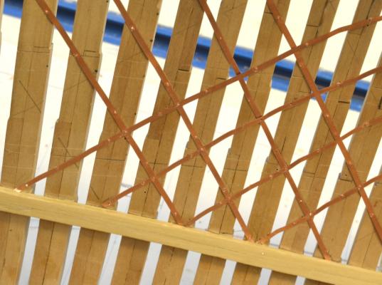
Thanks, Gary, Ian and Guy. Guy, the straps were on the order of 5/8" to 3/4" thick and about 4" wide. They were normally let into the frames on these classes of ships whether installed on the inside or the outside of the hull, so the frames had to be scored down to receive them. This would allow the planking to lay flat on the frames. It also probably added to the effectiveness of the strapping, but that is a guess. I had considered scoring the frames, but decided it was too much work - and too difficult to do well at this scale. Considering that most of this will be covered with plank and only visible from outside the hull, I decided to go with the method described. Ed
- 3,618 replies
-
- 1
-
-
- young america
- clipper
- (and 1 more)
-
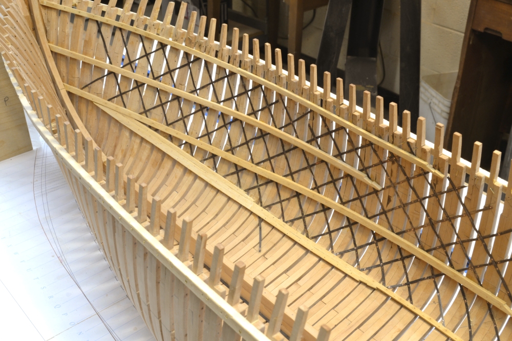
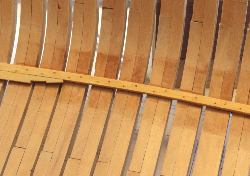
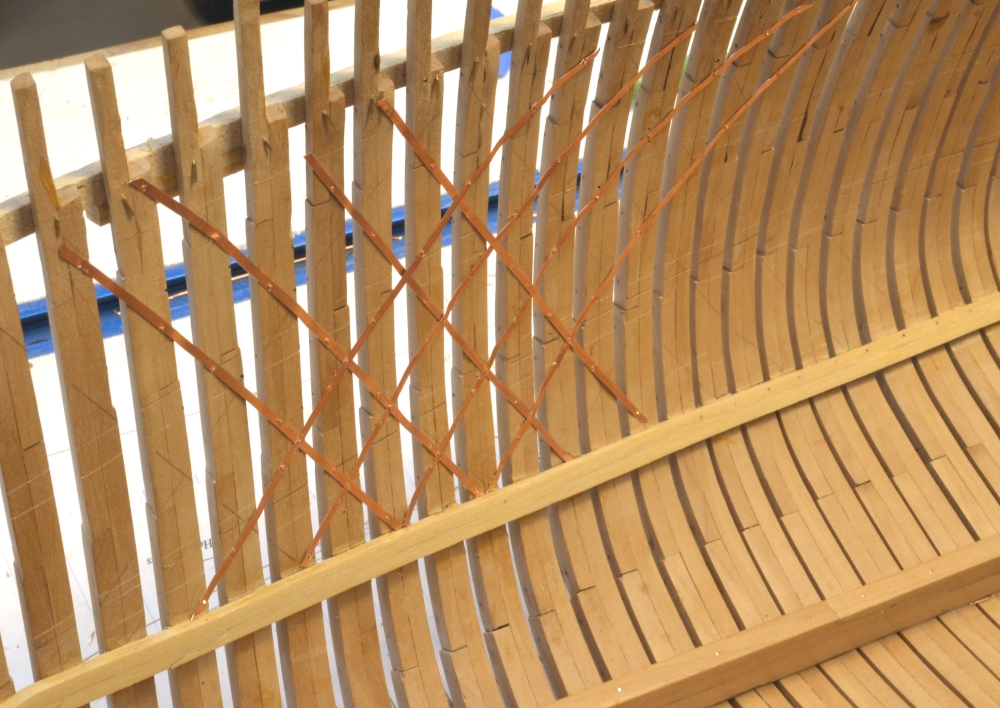
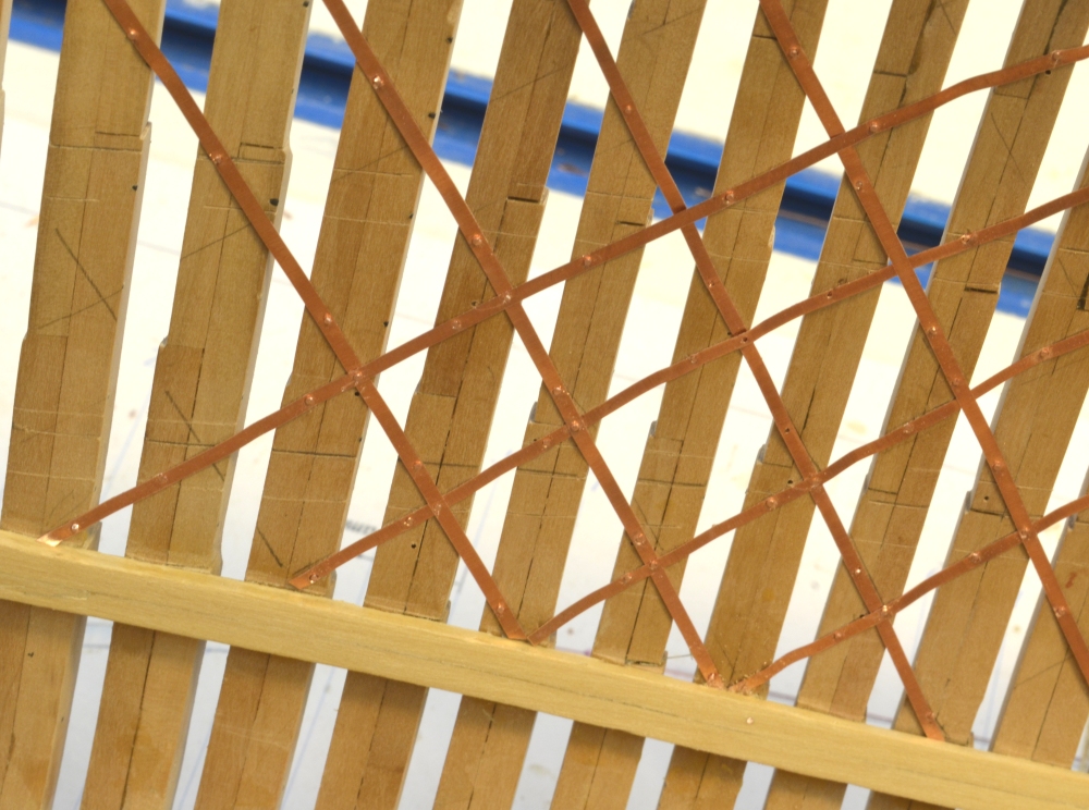
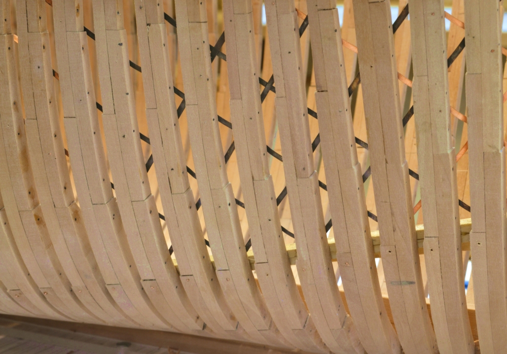
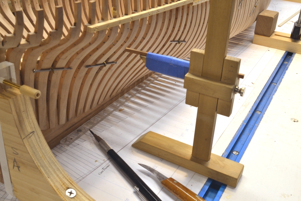
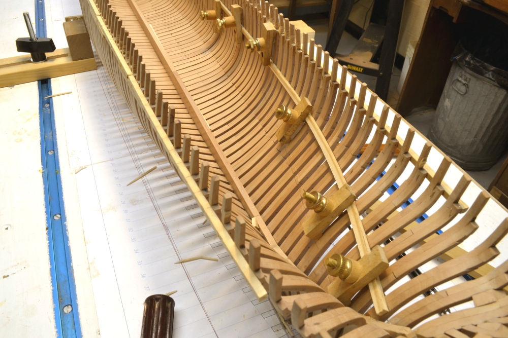
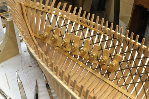
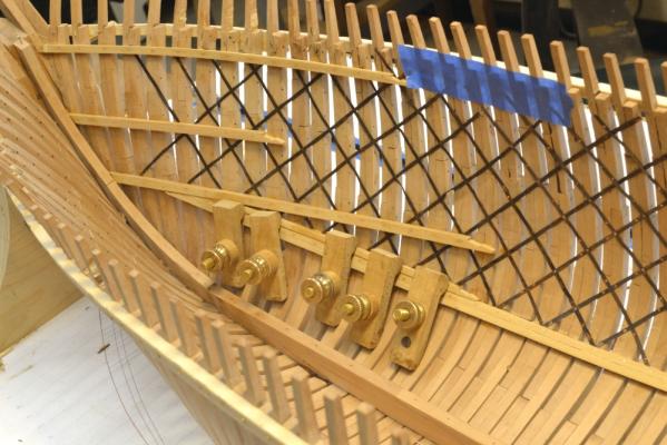
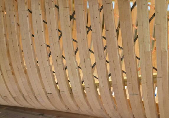
Young America - extreme clipper 1853 Part 43 – Bilge Ceiling, Iron Strapping Historical Clipper Note: A number of different structures were installed inside clipper ship hulls to increase strength and help defeat hogging, the most serious structural threat to wooden ships apart from rot. Hogging is the tendency of hulls to droop at the ends. It resulted from the reduced buoyancy at the ends of ships as the flotation area of the hull got smaller. It was further aggravated by localized stresses as waves passed under the hull. This was a particular problem in clipper hulls that were very long and had very fine lines fore and aft. In addition to large keelsons, weight reductions at the ends, moving foremasts aft and some features discussed in earlier posts, additional structural members inside the hull were also used. These varied from builder to builder. These included massive additional keelsons in the area of the floor heads, various forms of heavy ceiling timbers, long diagonal wood “pointers” and ironwork. From what we know of William Webb’s designs, he seemed to favor thick “bilge ceilings” – bands of heavy planking from below the lower futtock heads up to the lower deck clamps - rather than bilge keelsons or pointers. An 8” to 7” thick bilge ceiling and iron strapping were the most likely combination used in Young America and that will be the configuration I will use on the model After some deliberation – discussed in earlier posts – I finally decided to install the strapping on the inside of the frames. Although this is not known to be the original configuration, it is most likely based on some references and Webb’ practice on other ships. The strapping was installed on the frames under the ceiling planking. Because installing the strapping requires some hammering on the frames to rivet the straps in place, I wanted to get a couple of ceiling strakes in place to make the frame structure stronger before beginning the strapping. The first picture shows the first strake of the bilge ceiling being installed. These are 8” x 8” members bolted through the frames from a few feet above the floor heads decreasing in thickness to 7” up to the lower deck clamp The strake being installed is at the heads of the lower futtocks. This strake and the others in the band, follow the curve of these futtock head joints. Fore and aft they converge under the lower deck clamp to form a sort of truss to resist bending of the hull. This was definitely the configuration when bilge keelsons were used and it is likely the bilge ceilings followed this practice. Once this line is set by the first strake the others above and below it will be installed. The next picture shows a closer view of the bolting and one of the joint scarphs. Copper wire bolts have been epoxied through the frames. The dark area is isopropanol used to wash off the epoxy – not yet dry. Epoxy will help assure that the wire will act as true through bolts. In practice these were iron, so they will be blackened before final finishing. The second bolt at each frame pair will be modeled using black monofilament. The next picture shows the copper bolts coming through the frames outside. These will be clipped off and sanded flush as part of the external fairing process. It can be seen that the bolts come through the lower futtocks just below the heads. I am considering leaving a few view ports on the exposed framing side of the hull. The bottom of these open areas would be at the floor heads, so the bolted inside members should provide plenty of strength around the openings. The tops of these openings will probably be at the middle deck clamps. With a stretch of ceiling in place I was anxious to try out some iron strapping. The first picture shows the installation of a test area. I decided I wanted no part of recessing all these into the frames. For the most part they will be covered with inboard planking and will only be visible between frames on the outside, through the view ports if installed, and down through unplanked deck areas. The next picture shows a closer view of the straps and their fasteners. I used .005” copper for the straps, cutting them to size with a paper cutter, and then stretching to straighten them. I considered using .010” strips but these would require recesses. The thinner material should not affect the planking glue joints. Planks will also be bolted so should be quite secure. The difference in thickness is virtually undetectable visually. The actual thickness would probably be somewhere between the two sizes. The straps are held in place by copper rivets - 22 gauge copper wire – some through and some partially through as “blunts”. Like the real bolts, the heads are peened over to secure the strips. I initially tried to get all of the intersections on frames for bolting, hence some uneven spacing in this first area. I will not describe all the steps in detail – or the journey up the learning curve to get acceptable-looking straps. These must of course be blackened before being planked over – to avoid glue spots that would interfere with the etching. The next picture from outside the hull shows some strapping blackened using liver of sulfur solution. This will be the predominant viewpoint for this feature. This picture shows some inevitable crossing of straps between frames. I doubt that I will try to rivet these intersections as was done in practice, except where they fall over a frame. A few strapping rivet heads can be seen on the outside of the frames. The strapping will be installed over the full length of the hull up to the upper deck clamps. The next picture shows some correctly sized clamp material – for the lower and upper decks - temporarily held in place, This shows the convergence of the ceiling and the lower deck clamp mentioned above. The 7 to 8” bilge ceiling would fill the area below the lower deck plank and continue for a few more strakes below those installed in this picture. The straps will be cut off above the upper deck clamp. The strapping is fully extended forward in this picture. The middle deck clamp will fall midway between the two shown. I now foresee a considerable amount of strapping work, punctuated with some bilge ceiling and perhaps deck clamp installation. Should be interesting. Ed


- 3,618 replies
-
- 30
-
-
- young america
- clipper
- (and 1 more)
-
David, areyou referring to Micromesh pads or something else? Miromesh grits range between 1500 and 12000. Ed
- 3,618 replies
-
- 1
-
-
- young america
- clipper
- (and 1 more)
-
Thanks, Greg, Worth a look. Ed
-
Al, As with the pdfs on the CD, no problem printing copies as you need them for your use. Ed
-
Al, Thanks for your interest in the books. I hope you will enjoy them. Both books are in the first printing and do not include updates. Whenever an error is found - apart from minor typos - I post these on this forum on this topic or the one for Volume II. I have also posted useful supplementary information in a few cases. I suggest you go back through the postings and collect the various addenda. Ed
-
Thank you all for the comments and the "likes". Druxey, I have never tried bronze steel wool nor have I ever seen it. That would solve the magnetic problem. What I do now is avoid using steel wool when other tasks are going on and the bench is littered with tools - as it usally is, I'm afraid. Before using it I clear everything away and then vacuum it up as I go along. One benefit of steel - threads left in hard to reach places can often be collected with a magnet. Another benefit is that its readily available and cheap. David, I am assuming you are referring to the Micromesh pads and sticks sold by Micromark. I do use the sticks quite a bit and the pads for polishing metal before etching. The grades tend to be very fine - 800 mesh and to up 12000 if I am correct, so they often do not get cross grain scratches from previous sanding steps. Steel wool cuts fast and doesn't really care about grain direction even at coarser grades. I also use Scotchbrite pads quite a bit. They are similar to steel wool but do not work as fast. I often cut these into disks and us in a rotary tool to get into tight places but they don't last long in that service. Grey and white grades are most useful. Then there is always fine sandpaper. I use a lot of wet-or-dry 220 to 600. Ed
- 3,618 replies
-
- 2
-
-
- young america
- clipper
- (and 1 more)
-
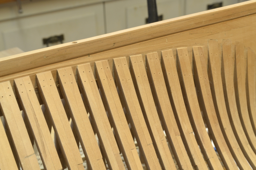
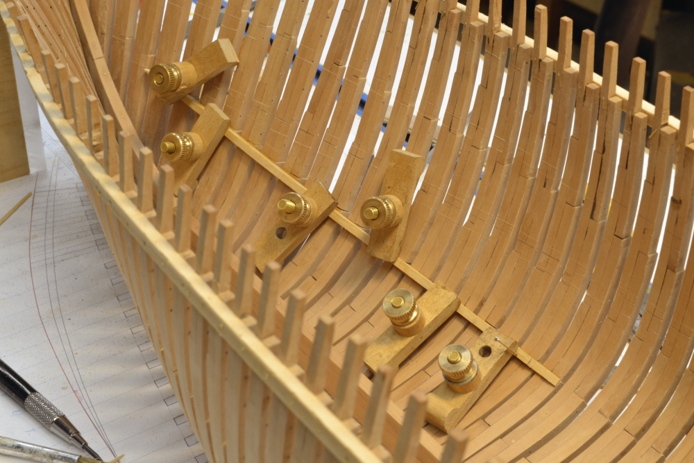
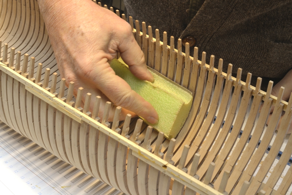
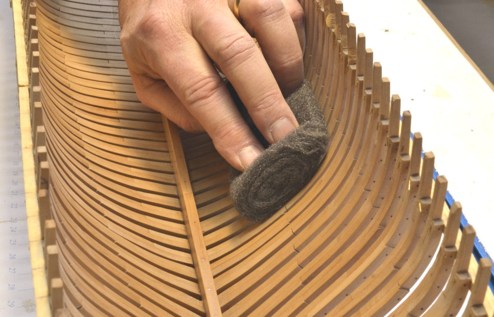
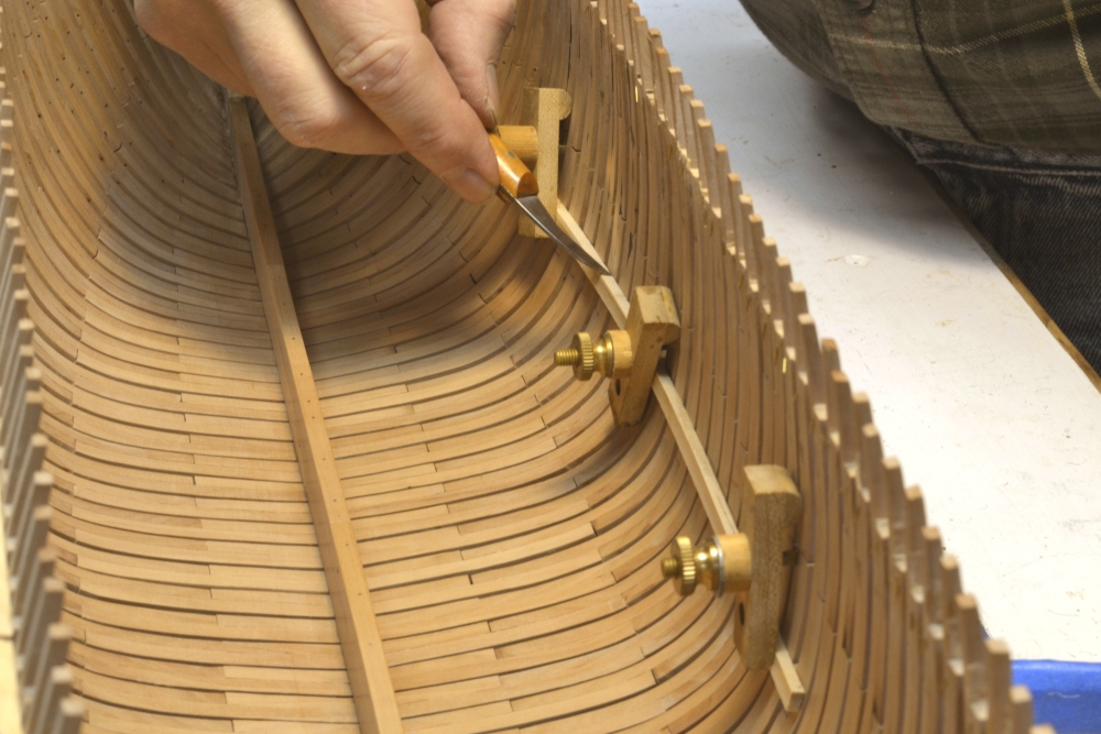
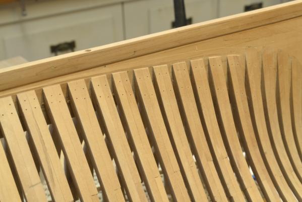
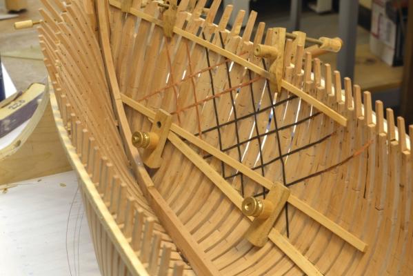
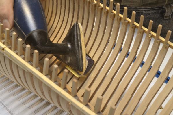
Young America - extreme clipper 1853 Part 42 – Internal Hull Work With the hull framing finished it was time to step back and consider the right construction sequence going forward. Rather than go to work fairing and sanding the outer hull as I has anticipated, I decided to focus next on some of the basic internal structural elements. Installing some key internal longitudinal members will add a lot of strength to the frames, in particular the connections of the full square frames at the keel. These joints are rather weak and may not stand up well to outside sanding. In practice this joint was strengthened by use of a very heavy garboard strake (the plank next to the keel) that was bolted up through the floors and lower futtocks. This 9” thick block was in turn edge bolted into the keel. The garboard was a much more important structural member in these ships than the familiar 18C RN subjects. The first step was to fair out the inboard sides of the frames. The full square frames had been carefully checked for fairness before locking them forever into place when the keelson was installed. The careful pre-beveling of the half and cant frames and the use of the topside ribband to set these resulted in a pretty fair surface. A few had to be removed and reset. The first picture shows the first sanding/fairing step using 120-grit paper and a “soft-sander” foam pad. Once all the surfaces were faired out with the 120-grit paper, 220-grit was used to start smoothing the surfaces. In the next picture a round piece of a soft-sander pad is stuck to a vibrating sander and it turn has some 220-grit paper attached to that – all with two-faced carpet tape, A few different pad shapes were used. This was followed by 320-grit, using the same device. There was also a lot of old-fashioned handwork with all this sanding. In the next picture the wood is being given a final polish with #0000 steel wool. I don’t like using steel wool very much – it leaves a lot of steel fibers lying around and this also adheres to steel tools. But after years of searching, I have found nothing that polishes bare hardwood like steel wool, so I am using it here - #1, then #0, then #0000. All the tools are cleared away before doing this and the shop-vac comes out frequently. With the inside of the hull given its final polishing, the lines of the deck clamps were scored on the frames as shown in the next picture. A thick pine batten was first clamped to the frames as shown. The heights of the clamps were taken off the inboard arrangement drawing with the calipers shown below. These will be familiar to those who followed Naiad. To allow the measurements to be transferred to the inside of the hull a thin strip was taped on top of the original arm to fit through the frame gaps. The next picture shows the batten set at the height of the middle deck. The lower deck clamps on both sides have been marked. The upper (or main) deck clamps will be just below and essentially parallel to the temporary ribbands clamped to the outside of the frames. When those clamps are installed, the outside ribbands can be removed Removing the temporary ribbands and strengthening the framing with internal members will allow the outside of the hull to be completely faired and finish sanded from the keel up to the top rail. In the next part members of the “bilge ceiling” will be installed below the line of the lower deck clamp. Ed


- 3,618 replies
-
- 26
-
-
- young america
- clipper
- (and 1 more)
-
20! Wow! That's a project. I have not seen Cutty Sark for almost 25 years. First visit was in 1970. British shipbuilding began the use of iron to replace wood even before Naiad, but the use accelerated in the early 19th century. This was due to the deforestation of Britain by the shipbuilding industry - especially the Royal Navy. In America there was no shortage of good timber - white oak, live oak and hard pine - so the American builders used wood throughout most of the 19th century - and well into the twentieth for sailing ships. Also, iron in America was expensive and usually imported well into the 19th century. Except for the iron strapping - coming soon - and of course the thousands of bolts - Young America was a wooden ship. Ed
-
A very good improvement, Salvatore. It allows the screw in the middle of the jaw to open the jaw when it is tightened. Very good. Helps close the performance gap between the two types. Another possible improvement would be to make the hole at the washer a slot. I believe this might give the clamp more flexibility. Ed
-
Me too, Christian.
-
ROYAL CAROLINE 1749 by Doris - 1:40 - CARD
EdT replied to DORIS's topic in - Build logs for subjects built 1501 - 1750
Doris, I am completely in awe of your work. I just don't know what to say, or where to begin. Almost unreal. Ed- 883 replies
-
- 1
-
-
- royal caroline
- ship of the line
- (and 1 more)
-
Richard, You are welcome, Richard. I am glad to help. You may want to consider starting with the simpler clamps. You can probably buy a 6-32 tap and 6-32 threaded brass rod at your local hardware store and certainly on Amazon.com. These clamps are easy to make and will work as well as the more complex ones in most situations. Of course the others can be a fun as well as a challenging project. I found it so. If you can't find the items you need, try this website. http://www.mscdirect.com/ If MSC doesn't have it, they probably don't make it when it comes to tools, etc. They used to mail their encycopedia sized catalog on request, but here is a link to their online version: http://www.mscdirect.com/FlyerView?contentPath=/sales-catalogs/big-book Browsing through this will give you an idea of their products and can also be an education in itself. I have had very good experience with them. Good luck. Ed
-
Thanks, Allan and Christian. Christian, I doubt that I would publish the drawings unless they were supplementary to a book. I am considering a possible book but have made no decision on that. Ed
- 3,618 replies
-
- 1
-
-
- young america
- clipper
- (and 1 more)