EdT
-
Posts
2,214 -
Joined
-
Last visited
Content Type
Profiles
Forums
Gallery
Events
Everything posted by EdT
-
I'm running out of ways to say thank you for all your comments, everyone. They are most appreciated. Just 25 more reposts to do and we can move on to new stuff. Ed
-
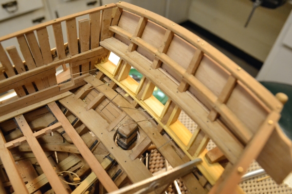
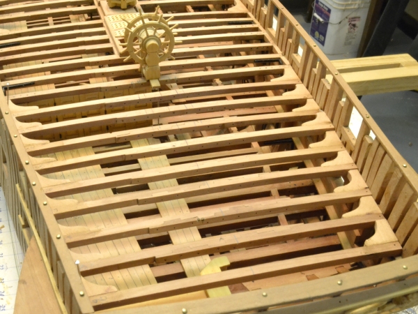
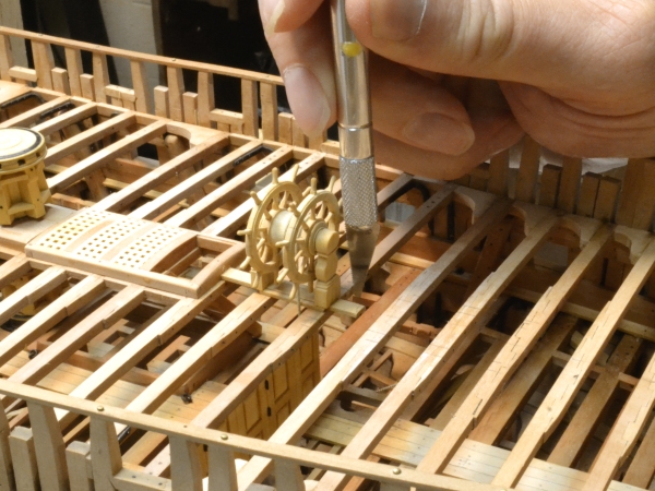
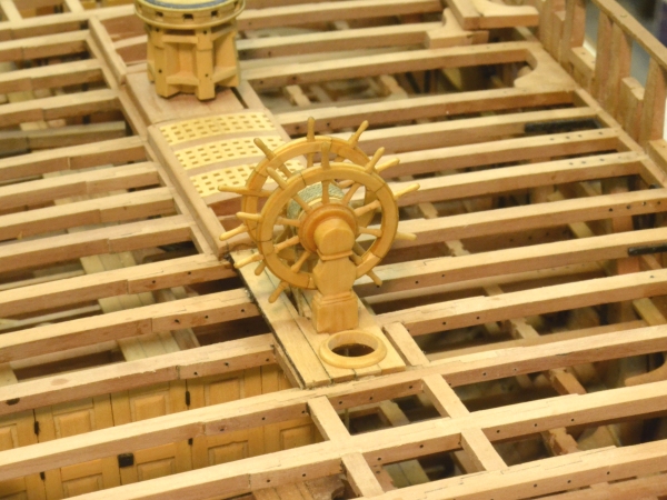
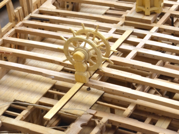
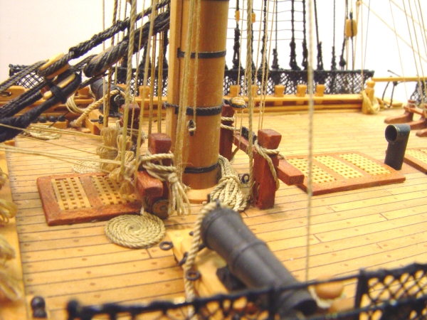
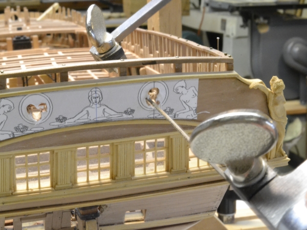
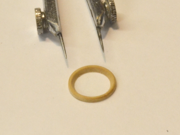
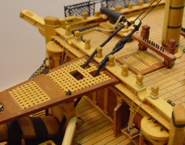
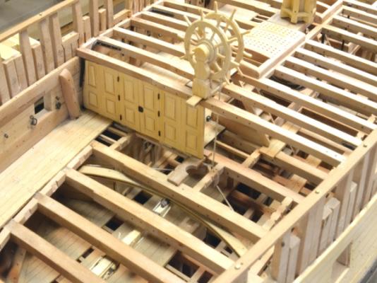
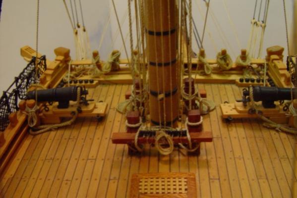
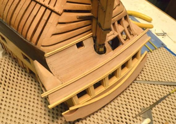
1:60 HMS Naiad 1797 Part 150– Aft Quarterdeck Beams Posted 9/25/12 Moving right along this week. Anticipating the completion of the quarterdeck framing, I applied the turpentine wax finish to most of the upper deck framing, decking and sides – excluding the area where the captain’s cabin partition will be installed – while access was available. The contrast between the unfinished and the finished areas can be seen in the first picture. The next picture shows the finish on the deck framing and sides on the starboard side. All the accessible areas on the upper deck were finished at this time except as mentioned and also in the waist where the beams still need to be installed. The next picture shows the remaining quarterdeck beams aft of the wheel fitted with their lodging knees and set temporarily in place. The mizzenmast is just aft of the wheel and there are some eyebolts in the deck on either side. I had neglected reinforcing carlings under these on the drawings and so did not cut seats in the beam at the aft side of the wheel. In the next picture this is being corrected. The bunker had to be removed from the wheel for this, so I was extra careful using the saw and chisels for this work. In the next picture the next two beams with carlings are being installed. In the next picture the decking on either side of the wheel pedestals is being installed. I figured I’d get all this work done while the lid was off the wheel. In the next picture the ends of the planks have been trimmed and the mast ring installed. The whole for the mast was cut in the planking in place – another risky process next to the exposed wheel. The planks butt up against the fore side of the companion – the glazed set of windows that illuminated the coach underneath – to be installed later. The mast ring was turned in boxwood and has an opening just over 18” in diameter. In this picture the wheel has been given a coat of wax finish. The next picture is a close up of this work. The plank on the near side shows a dark painted edge. I use dark paint to highlight the caulked joints. The paint is applied before the planks are ripped to thickness. Additional planking is to be installed on this side. As soon as this work was done the bunker was replaced over the wheel. Fortunately no mishaps. Ed


-
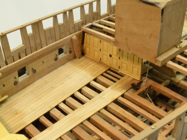
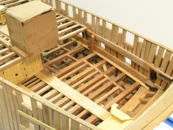
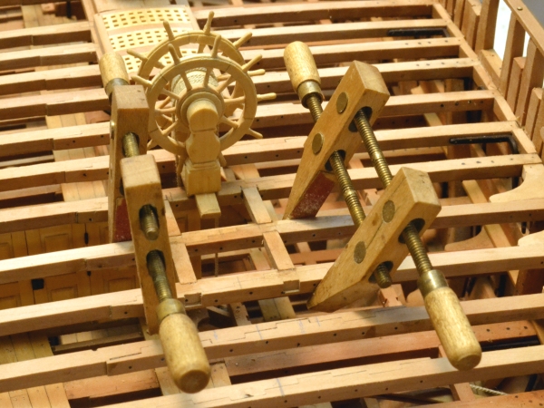
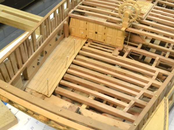
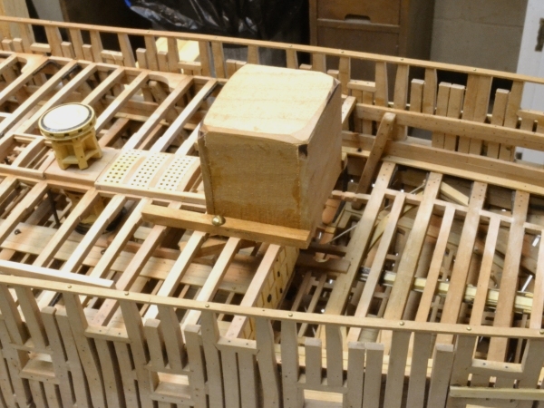
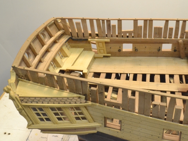
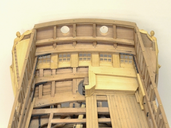
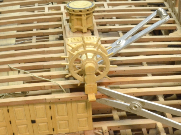
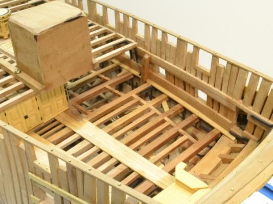
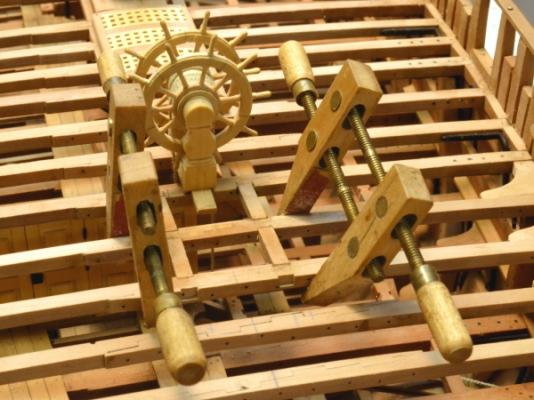
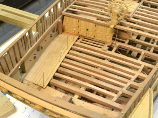
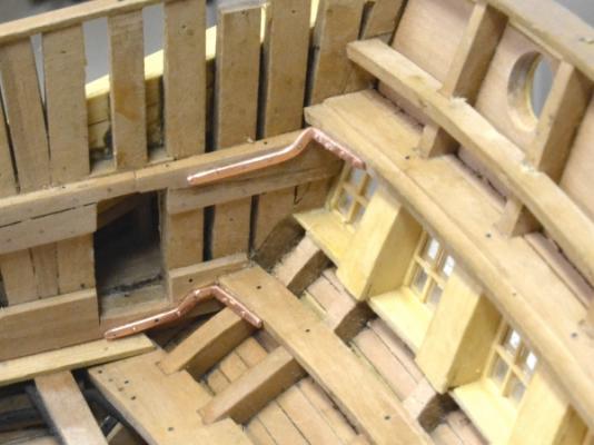
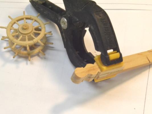
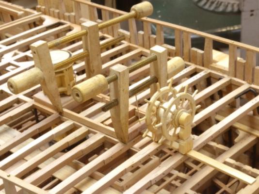
1:60 HMS Naiad 1797 Part 149– Captain’s Cabins Posted 9/23/12 It has been a few weeks since the last post. I had some other things to do and spent the last week lying on the beach. Now back to work. In the last part the steering gear was rigged. The remaining framing of the upper deck – the ledges aft of the partition and the four half beams over the tiller – could then be installed. The first picture shows these additions. In this picture the decking is being installed aft of the partition on the port side. The cants at the base of the partition are installed after the decking. Before much of this work was done it was clear that the steering wheel needed some protection from me. With all the rigging now buried under structure, any breakage at this stage would be very hard to repair, so the bomb shelter shown in the next picture was installed before going any further. This strong cover was made from scrap hardwood and clamped on the beams with a screw on each side. I think that even I will have a hard time breaking this. Before detailing the cabins, the iron transom knees were installed. The next picture shows these for the upper deck seat transom and the quarterdeck transom – on the port side. The fore and aft legs of these knees jog down to fit under the deck beams and the opening to the quarter gallery. I see one bolt missing in this picture – one of the reasons I take pictures. The next picture shows these after blackening. A similar knee, installed much earlier, for the upper deck transom, can be seen in this picture. The next picture shows one of these knees on the port side after some of the finish carpentry in the great cabin was installed. The lower knee is hidden with a step under the opening to the quarter gallery, which is fitted with a sliding door. The wide benches are typical of frigates, where this cabin is directly above both the lower and the upper counters. Larger ships provide the captain and/or admiral with a lot more usable floor space. This picture also illustrates why aft chase guns are impractical on this deck. This finish work is installed on the port side only. The hexagonal cabinet over the rudder head is cut away to show that detail. None of this wood work has had finish applied. The next picture provides a larger view. There will be a partition across the deck between the two gun ports in this picture. The next picture provides a closeup. This degree of finish work was deemed sufficient for the lowly frigate post captain – no paneling of the sides, some exposed ironwork, and of course the floor space reduced by the wide benches. The last picture shows the great cabin from above. Except for the partition separating this area from the sleeping cabin and the coach this is the extent of the interior work. This picture also shows the cutaway of the rudder cover and the full structural detail on the starboard side. Ed


-
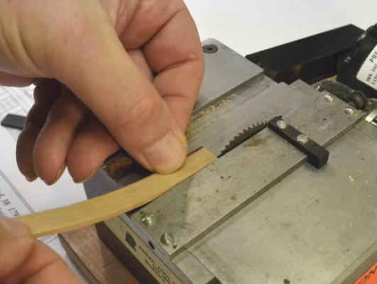
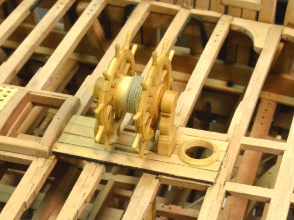
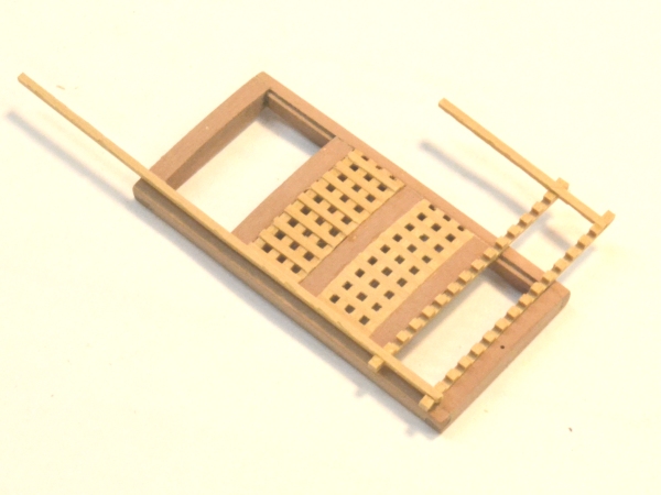
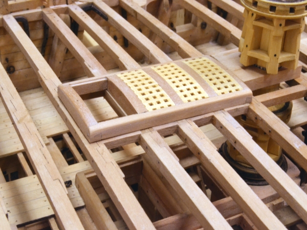
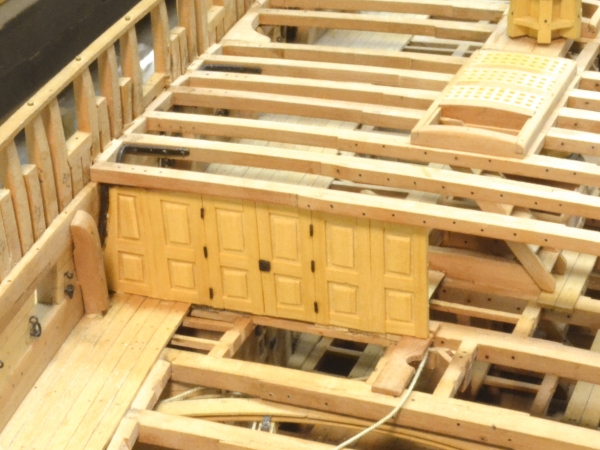
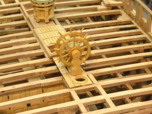
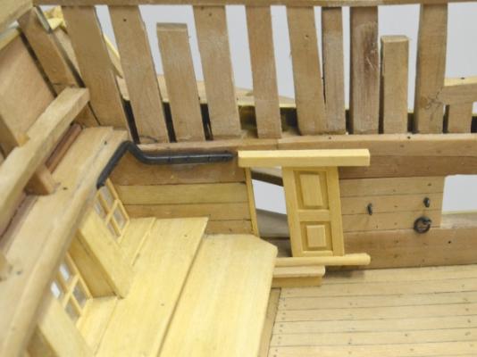
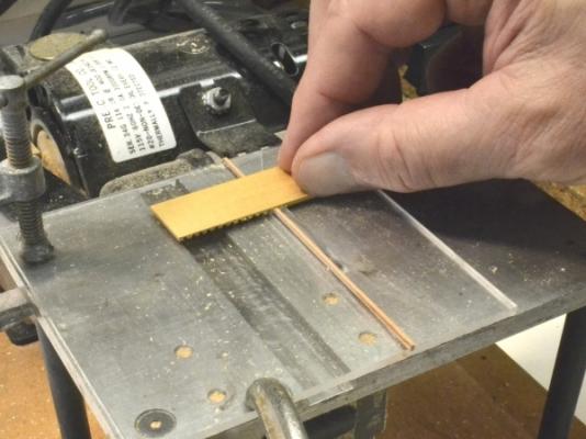
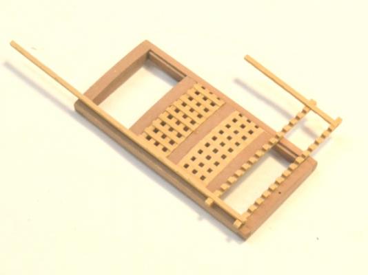
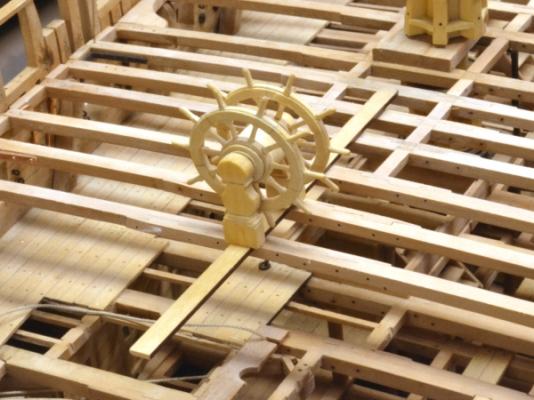
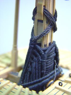
1:60 HMS Naiad 1797 Part 148– Installing the Wheel 2 Posted 9/4/12 In Part 147 the framing of the hatchways between the capstan and the wheel were constructed. Three of the openings have gratings and the third is a ladderway. In the first picture the grating ledges are being formed on the circular saw with the help of an auxiliary Plexiglas® table with an inset guide strip. The blade is a .045” slotting saw. This is equivalent to the 3-inch width of the grating sections. The guide strip and the distance to the blade are both the same measurement (.045”). The next picture shows the gratings being installed. The center grating is finished. Before installing it was curved to match the curve of the head ledges by passing it across the shoulder of a 25-watt soldering iron. The grating to the left has not been sanded yet. The one to the right had to fit in a very slightly larger opening, so the first strips were glued in using the opening as a guide. The remaining to ledges were spaced in between. The difference in spacing is unnoticeable as can be seen in the next picture. Here the assembly is almost ready to be glued. It just needs a few bolts holes for locating pins. The corners of these hatchway frames will be rounded after the decking is installed. The next step was to install the forward bulkhead to the captains quarters to stiffen up the beam under the aft pedestal of the wheel. This is shown in the next picture. The paneled sections are 2’ 6” wide and were built up using thin boxwood stiles and panels on both sides of a single thin boxwood sheet cut to fit the space under the beam. The door hardware is ebony. The next picture shows the wheel assembly being glued down to the beams. Finally, after the glue on this dried, it was time to rig up the wheel and see if it would move the rudder. The next three pictures show the final rigged wheel – and I am relieved to say it works. It turned out to be much easier to thread up than I had anticipated. I had left off the framing and decking over the tiller assembly to be able to access the tiller tackle that was installed much earlier. With the rope threaded through and put under tension, a seizing was tied just forward of the tensioning tackle then given a drop of glue. The last picture is a closeup of the wheel showing the wrapping of the rope. The picture also shows small strips on either side of the central plank. When the adjacent slotted planking is added these strips will appear to be part of those planks. The aft end of the central plank will later be shaped to fit around the mizzenmast opening. I have been working toward this milestone for some time. It allows the remaining upper deck framing and the detailing of the captains’s cabins to proceed. Ed


-
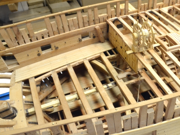
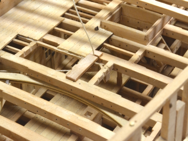
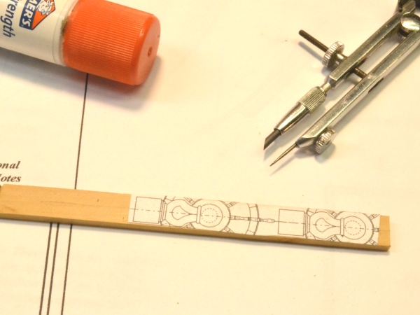
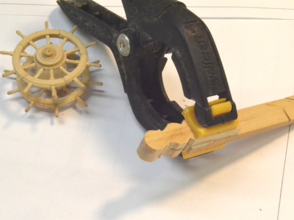
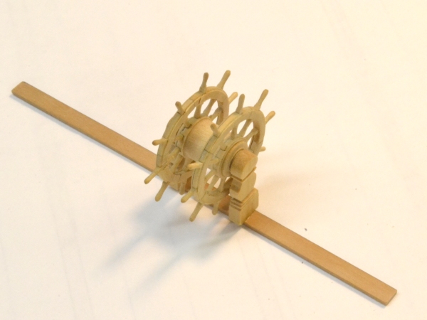
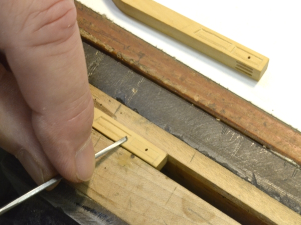
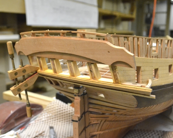
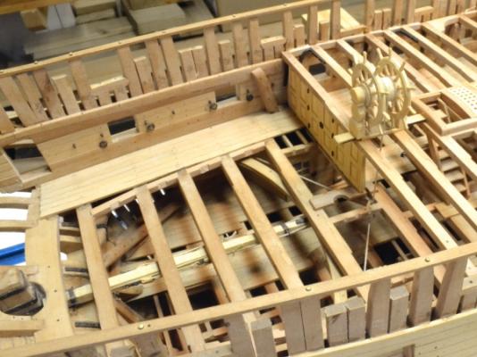
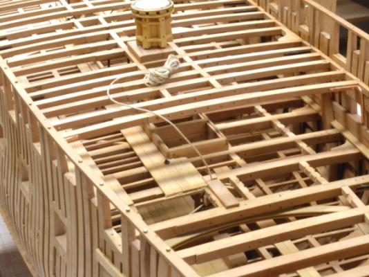
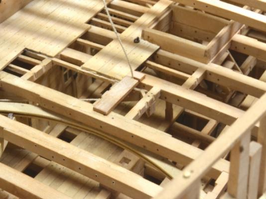
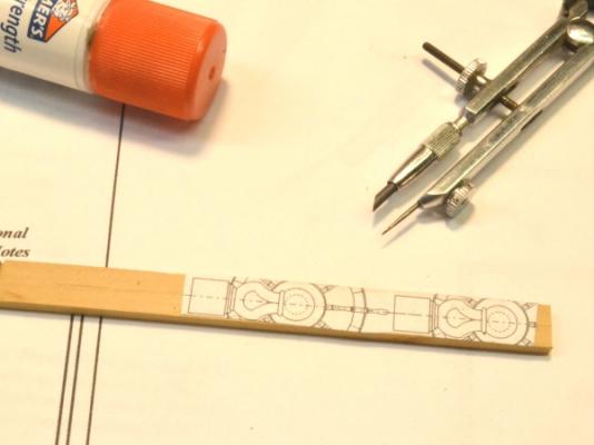
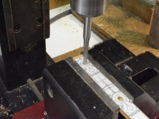
1:60 HMS Naiad 1797 Part 147– Installing the Wheel 1 Posted 8/29/12 Its been a few weeks since the last update – a lot of summer chores had to get done. The next major milestone is to get the quarterdeck framing finished back to the bulkhead that separates the captain’s quarters on the upper deck and to get the wheel and its ropes installed so the decking aft of that bulkhead along with the other work in the cabins can be completed. That part of the upper deck framing needs to be left open for the rigging of the steering gear.. The first picture shows the next five beams aft of the capstan installed The carlings for the hatch coamings between the capstan and the wheel are also installed, as is one half of the simple upper deck partner for the mizzen mast. This has been bored for the steering rope but not yet for the mast. The rope is for the steering gear, which is one half rigged below the upper deck aft. The next picture shows a closer view of this. The starboard half of the mizzen step will be left off to allow visibility of the sheaves for the steering rope that are fitted right below it. The inauthentic plank endings in this picture will be covered by the captain’s cabin bulkhead. They had to be installed this way (and treenailed) so the beams above could be installed. The wheel was made some time ago. The next picture shows a step in the modeling of the wheel support stanchions. Stanchion patterns were pasted to a strip of boxwood in line with a centerline that had been marked (with the compass). The next picture shows the boring of the bearings in the top of the stanchions. This sequence assured that the bearings would be centered on the strip. The stanchions were then cut out on the scroll saw. The next picture shows them glued together with a paper joint to permit their final shaping. A short bit of dowel was placed between these parts in the bearing recesses to maintain the alignment for the final shaping. The next picture shows the wheel mounted on the finished stanchions. The wheel/stanchion assembly was glued to what will be the central deck plank. After this glue had set, two copper bolts were CA glued from the underside of the planking up into each stanchion for strength. The excess plank will be cut off later before this assembly is installed. The next picture shows the assembly set on the deck beams. Once this is installed the next adjacent planks will be slotted to take the steering rope. This cannot be done until the grating hatchways structure just forward of this are installed. The next picture shows the coamings and head ledges for that structure being glued together. Both these assemblies are still loose. The coaming structure will need to be finished, rounded up and have its gratings installed before final attachment. The plank under the wheel has been cut to size on its forward end, but still needs to be marked and cut on the aft end. Stay tuned. Ed

-
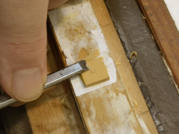
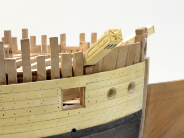
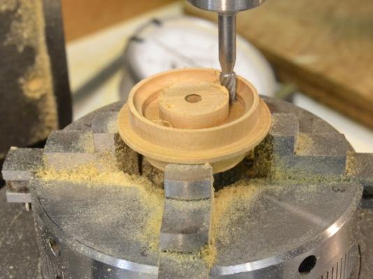
1:60 HMS Naiad 1797 Part 146– Capstan/Cathead Detailing Posted 8/4/12 To finish up on the capstan: The first picture shows the hole in the quarterdeck step being bored on the lathe. The hole was sized to fit the bearing area on the capstan barrel. Two of these were made, then split down their centers to make two equal halves. The next picture shows the two part step being glued in placed around the capstan. Once the capstan was completely fabricated and finished, the next beam aft of it was installed with it in place. It will not fit between these beams in one piece. I did not want to make the single barrel in two pieces. The step carlings were then installed followed by the step itself as shown above. There will be hatchways and gratings fore and aft of the capstan. The next picture shows the finished installation without the aft beams in place. The starboard side of the upper step was cut back to just enough to hold the capstan securely in place to allow visibility from the starboard side to the lower parts. Unfortunately all those iron strips on the barrel bearing face are not visible. I had not fully detailed the catheads earlier and decided to do that now. The paneled surfaces on the side were cut as shown below. The next pictures show some of the work on the end caps carving. The first step on these small star carvings was to face turn the buttons in the center on the lathe with the small square piece set up in a four jaw chuck. The area around the button was then pared back. It is glued to a piece of paper on a wood block. This piece of paper saw a lot of use in carving the taffrail figures. The final size of the endplate was drawn on the piece. The points of the star were then laid out by scribing lines to each of the centers of the sides and the corners – all tangential to the round button. The eight point star shape was then carved out with small chisels – using an optivisor. The next picture shows the starboard cathead installed. The planking on this side will be completed right up to the topside. And the last picture shows the installed cathead on the port side. As I have mentioned before, the port side will be unplanked, except in areas where structure is built over the planking. The port head structure will be built over the planning in this picture. Now back to those dreary deck beams. Cheers, Ed


-
Correction to the last post: In the last sentence I said the real capstan probably relied on its weight to keep it down. Actually there were vertical "muntins" fastened to the barrel below the bearing that acted as stops to prevent the capstan from rising. Wood pieces were fit between these at the bottom of the partners - perhaps as a grease seal. Ed
-
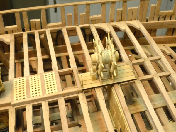
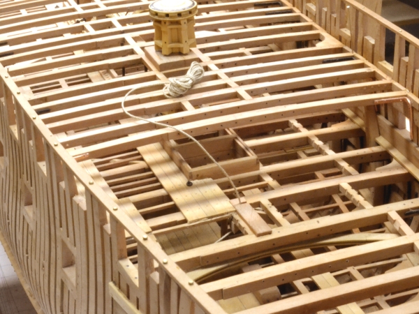
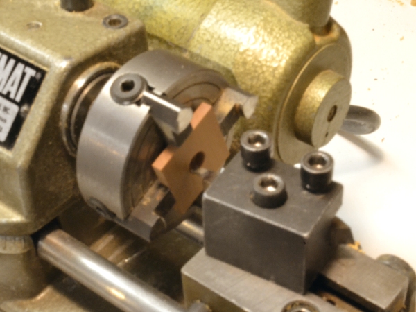
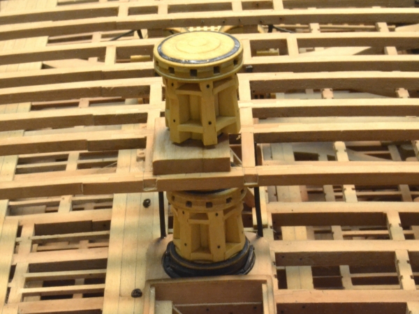
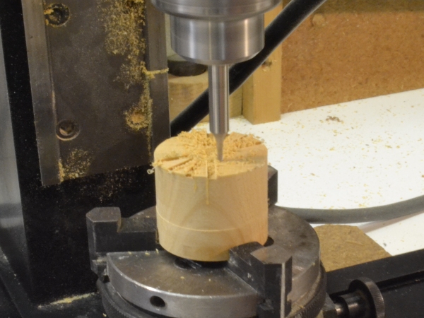
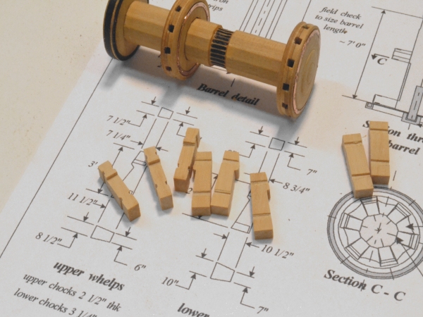
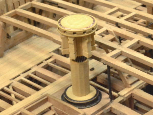
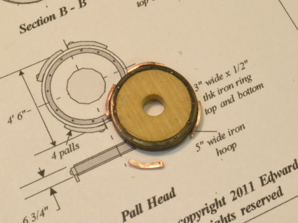
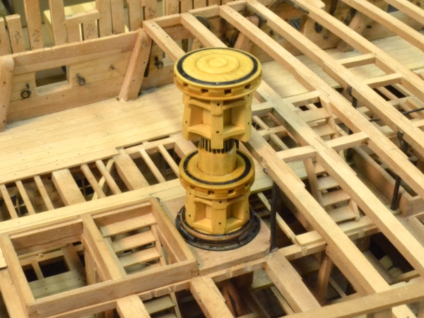
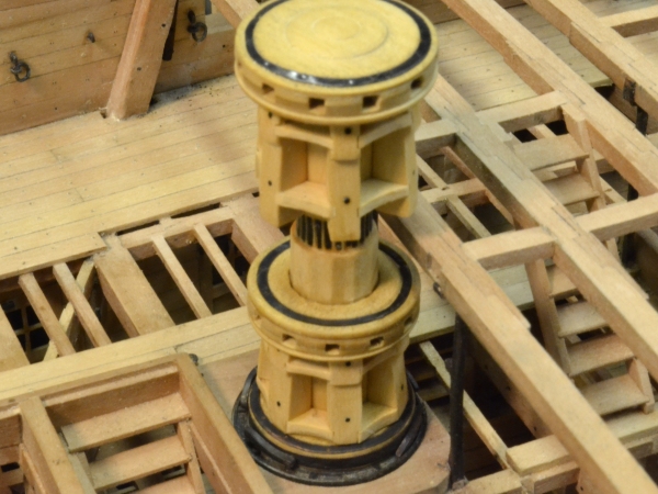
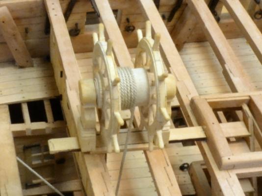
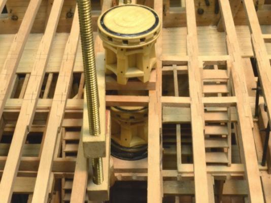
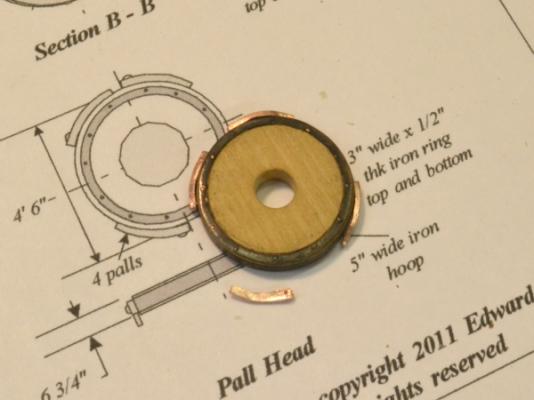
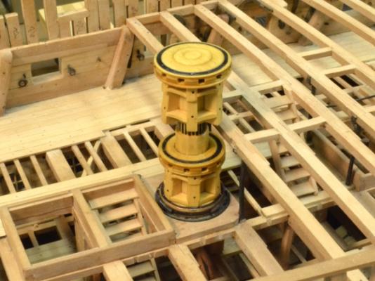
1:60 HMS Naiad 1797 Part 145– Capstan Posted 8/1/12 First, many thanks to the administrators for making more upload space available – so I’m back to the old format. While everyone was focused on my hard earned scrap pile (really guys!), I was busy finishing the capstan which I started back in Part 130. But first, here’s one last picture of the taffrail figures after giving them a bit of finish to bring out the relief. They look better with the finish. I used the wax and turpentine mixture that I have used everywhere else on the model but added just a trace of a dark Minwax stain to the solution to put some darkness into the cuts. The work on the stern decoration is now essentially complete. I have been relieved of the agony of lettering the name on the upper counter by the Admiralty order, probably around the start of the war with France (1793?), that ordered the discontinuation of name boards. I thought I had a nice solution for this task but it didn’t pan out. Fortunately I didn’t need it, but I tested it out anyway without success. No mystery. I was hoping to make my own dry transfers from inkjet printouts. Turned out looking like decals. On to the capstan. The barrel, the drumhead and the pall head were made earlier. The next step was to make the trundlehead - the head on the lower assembly. The first picture shows the machining of the square holes for the bars. The top of this was parted off on the lathe as a disk, the same milling operation was the performed on remaining piece, these were then glued up cross grain, and the trundle head was the turned on the lathe. At the suggestion of Keith, I used a dial indicator to center this so the slots would be centered on diagonals and therefore match with the mating piece. A very helpful suggestion. A Unimat 48 tooth indexing head is being used in the picture setup in the Sherline mill. A rotary table could have been used but I like the positive indexing of the gearhead and this also allowed me to use the same chuck for the slotting and the turning. The next picture shows the completed trundlehead (in the center of the barrel) and the other two heads fitted to the barrel along with the upper whelps that fit to the barrel under the drumhead. There is another set of these – different sizes of course – on the lower part. The copper reinforcing rings on the heads were photo-etched copper and are secured by small copper wire “bolts” – no cement to mess up the blackeneing. The whelps were made by hand. After cutting the scores for the chocks in a single, wide piece of Boxwood, the whelps were parted off and the outside faces shaped. The two to the right are just-in-case spares and never did get shaped. The next picture shows the upper whelps installed and the assembly set up in place The bottom of the whelps clear the top of the quarterdeck step, which will be installed later. Because the heads are larger than the beam spacing, the capstan needs to be in place before adding the next beam. The next picture shows the pall head in the process of having its ratchet arms installed. . These will ride in the pall ring inset in the upper deck step where stops are installed to prevent reversal of direction. Finally, the completed capstan is shown in position inside the pall ring on the lower step. After polishing the wood and metalwork and then cleaning the copper with acetone, all the metal was blackened with liver of sulfur. The black monofilament bolts were then added and the entire assembly given a coat of wax finish. It will tone down a bit when dry. The last picture is a closer view. The ratchet arms are visible in this picture. The iron strips in the barrel below the quarter deck were installed as a bearing surface. The entire assembly is supported on a metal shaft a metal cup bearing set in the lower step. The upper step will be installed in two pieces around the barrel. There is nothing to keep the assembly down. I may need to add something. The real capstan probably relied on its weight, and since no one was turning the ship upside down… Cheers, Ed


-
The Naiad Frigate - Addendum 3 Attached are corrected pdfs for the two stem patterns sheets. The breadth of the pieces to be cut out for the lower stem were incorrectly shown as 13.5". The dimension should be 1'3.5" (15.5"). Naiad 60 Stem Apron Patterns Starboard.pdf Naiad 60 Stem Apron Patterns Port.pdf Please replace the copies in the Stem Head Patterns folder on the CD. Sorry for any inconvenience. Also attached is a listing of the full-sized drawings included in Volume I and to be included in Volume II. This excludes the many letter-sized patterns and detail sheets. Naiad Frigate Drawing Lists.pdf Volume II is proceeding well. All of the chapters have been written and are being reviewed before submittal to the publisher. Drawing checking is almost complete. Keep an eye on the SeawatchBooks website for expected release. Ed
-
Salvatore, Thank you for pointing out the error on the two stem pattern sheets. I have made the correction and will post corrected sheets here, as soon as I double check for other occurences of this. The error arises from my confusion between 1'3.5" and 13.5". I hope this has not caused too much inconvenience. Egen, Thank you for posting the picture. There will be 9 full-sized drawings with Volume II. I will post a list. I am, however, confused by your question. None of the Volume II drawings are needed to complete the work in Volume I. Also, I do not understand the second question on the building jig. If you can clarify, I will be glad to respond. Are you asking about the building board or the drawing to use on it? Sorry. Ed
-
Hi, Guy. No, I do not glue the frames to the glass, just around the outside with wood glue. Ed
-
HMS Victory by EdT - FINISHED - 1:96 - POB
EdT replied to EdT's topic in - Build logs for subjects built 1751 - 1800
Thank you, Grant. Your comments, as always, are appreciated. As I look back on it now, after the work on Naiad, it seems a long way off in both time and experienced gained. It was my first, so I am proud of it, with all its faults. It still sits behind me here, in the window, as I type this. Perhaps it will soon be replaced with the frigate. Thanks again for your comments and continued interest in the work. Ed -
HMS Victory by EdT - FINISHED - 1:96 - POB
EdT replied to EdT's topic in - Build logs for subjects built 1751 - 1800
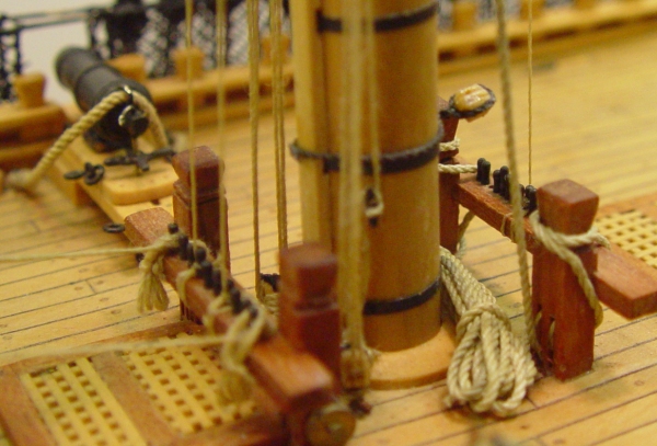
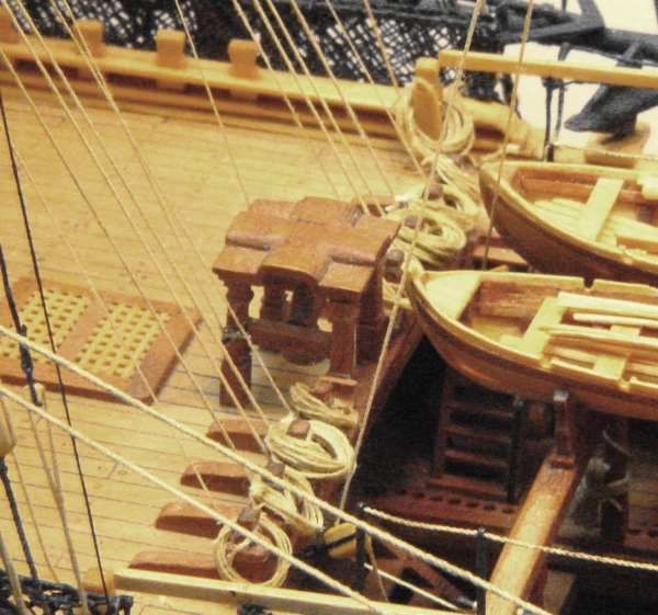
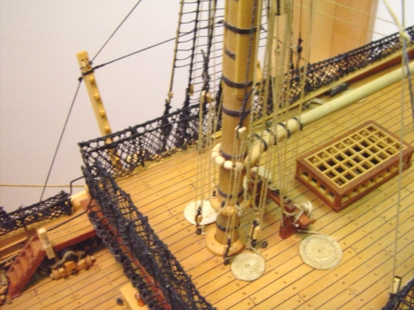
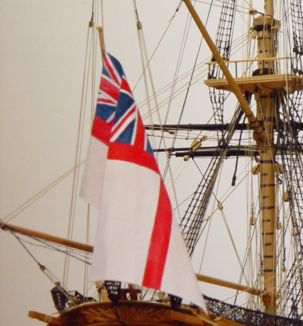
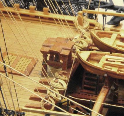
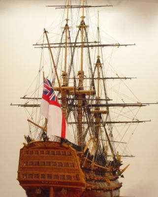
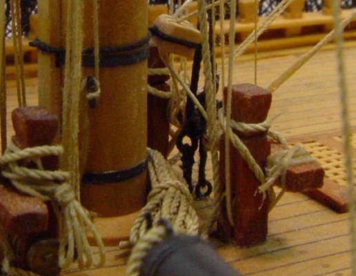
HMS Victory 1:96 Scratchbuild Project Part 19 – Wrapping Up At this point just about everything I had on my list has been covered. In this last part I will cover a couple incidentals involved in wrapping the project up. Excess Rope If one looks at the lengths of rope specified in Steele’s, or even just thinks about how much rope would be left over when a line was completely hauled in, it becomes evident that there must have been an amazing amount of rope lying about the deck, especially when no sails were set and buntlines, leechlines, slab lines, bowlines, clue lines, and others were with drawn back to some stowage point ready to be let out when sails were set. I decided very early on, that I could in no way model all this clutter without obscuring a lot of the model, but I did want to model some. The following pictures illustrate how some of this was done. Among the first excess lines to be dealt with were the fore yard jeer falls. With the yard hauled up to its normal position, from which, I believe, it was hardly ever moved, a long length of large rope remains. Seldom used, it is unlikely it would be kept too readily available. I decided to coil it up and stash it behind the mast out of the way. The main yard jeer falls are belayed on the upper gun deck out of site, so were not an issue. Many lines belay on the forecastle rail where they are tied off to the timberheads there. Only some of these excess rope coils were modeled. Coils were made by wrapping line around a tapered dowel, tying it off, removing it from the dowel and soaking it with flat acrylic emulsion. This left a flat finish and stiffened the rope so it stayed in place when draped over a timberhead. Coils secured around their middles were wrapped around bent wires inserted into the point grooves in a pair of screw adjustable dividers. Then when the right length was wrapped up, several turns were taken around the middle, finished off with a clove hitch and this, too, got soaked with emulsion. The dividers were then closed enough to remove the coil. These then got draped on timberheads, kevels or even tied up on a shroud if the rope was belayed there. If these coils are draped while the emulsion is still wet, they can be shaped realistically. This shape will be retained when they dry. Here are some more of these on the timberheads at the fore end of the waist. The next two pictures show lines that have been “flemished,” that is, wound into a neat circular pattern on the flat of the deck. I reserved this treatment for large lines that I expect were frequently used and therefore needed to be readily available. In the first picture below those astride the mizzenmast are the falls of the davit lifts, and those further aft are the mizzen topsail sheets. The flemished lines in the next picture are the fore top sail sheets. These arrangements were made as follows: First a small piece of paper was laid on a piece of soft Homosote board. Homosote is a compressed pulp sheet product that takes and holds pins well. A pin was then pushed through the rope near its end and pushed through the paper into the board. Titebond glue was thinly spread on the paper around the pin and a couple turns of rope taken around and pressed down on the tacky glue. At this stage the paper itself could be rotated on the pin with more rope being fed and pressed down until the desired diameter was reached. The rope was then brushed lightly with some water to bring the glue up into the rope, the pin carefully removed, a piece of waxed paper put on top, and the whole affair weighted until dry. When dry, the paper was trimmed back under the outer coil of rope with scissors. The paper was then glued down to the deck and the end of the rope tucked up to appear to emerge from its belaying point. Flags The very last item to be dealt with, aside from the case, was the question of flags. The decision on which flags to fly could result in a number anywhere from zero to probably 25 or 30, if signal flags were flown. I had diagrams for all the historic, “England expects … “ signal flags, and I had gathered data on which pennants, ensigns and other flags were likely flown at Trafalgar. In the end I settled on only the large white ensign. I find at times even this can be a distraction from what is meant to be shown on the model, but it can be easily removed, so there it is. Its quite large, 20 by 40 feet, as can be seen below. The ensign was made from some very old fine weave drafting linen, from which the resinous wax was removed by boiling. A larger piece than required was then pressed with a steam iron and taped down flat on a board. The ensign pattern was laid out with a sharp pencil and the white, blue and red colors painted on both sides with acrylic designers guache. This was thinned only very slightly to avoid running and painted on in two coats on each side. The ensign was then trimmed to size, pressed again and draped to appear standing in still air. So, this story began with a picture of Victory approaching and it ends with a view from astern. I have enjoyed describing my experiences with the construction of this model, which spanned a period of over thirty years. Many were surprised to see it finished – and I was one of them. Looking back while writing all this has made me appreciate the time spent even more. I hope this series has been helpful in some way to those who have followed it and especially those who have stayed with it to this point. As I said at the start, I did not plan to cover every step in the construction of this model. However, if there is some point of interest that was not covered please let me know and I will try to cover it. Thank you for spending time with this and especially for all your comments, suggestions and generous compliments. I expect soon to be posting a new series on my current modeling project, a fully framed 1:60 model of HMS Naiad, 38, 1797. Ed Tosti


- 57 replies
-
- 10
-

-
Martin, I do not intend to paint anything. We do not know what the original decoration was so this is all speculative. We do know that at the time, the Admiralty was cracking down on decorative carving and trying (we don't know how successfully) to eliminate it. Yes Druxey, I agree on the open space. A few months ago I added some more water lilies. If I were doing these figures again, I believe I would also extend the arms of the figures just outside the ports up to the cap rail as in the original painting. I don't have the heart for that at this stage, although I may include a pattern for that pose in Vol2. Attached photo taken in February. Ed
-
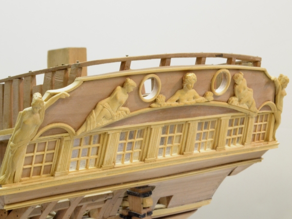
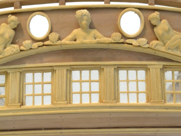
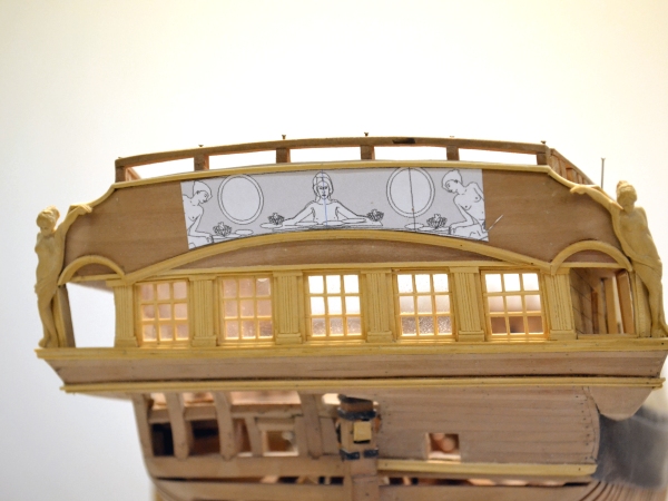
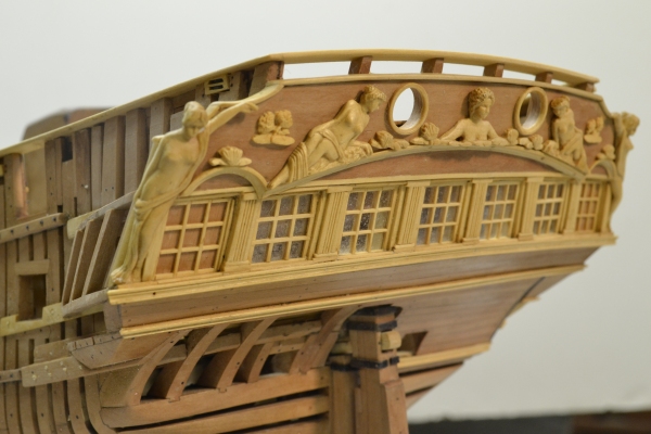
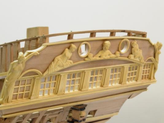
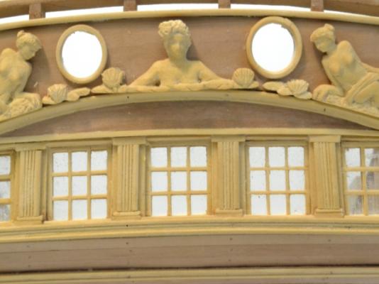
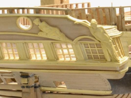
1:60 HMS Naiad 1797 Part 144–Stern Galleries 10 – Taffrail Figures Cont. Posted 7/23/12 Work continues on the taffrail figures. The first picture shows the almost complete central figure temporarily pasted in place. The others were permanently installed last week. The next picture is a closer view of the central figure, a naiad in a pool of water surrounded by water lilies. There is no finish on these figures so the relief is still somewhat obscured by the sanding dust. These actually look better in real life – not always the case with the Naiad model photos. I may do something with the finish to accentuate the relief. Perhaps the wax will suffice but I may go to Tung oil. We’ll see. First some tests. Fortunately there are lots of first draft figures to practice on. The next picture shows the taffrail with the additional groupings of water lilies added. These are just pasted on. Some more fitting of all the last parts is needed to integrate them into the taffrail. The last picture shows a view from below the starboard quarter. The angled lighting helps with the relief in this photo. Ed
-
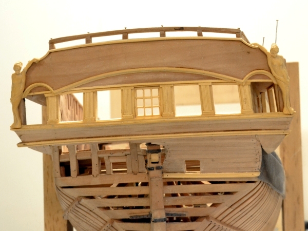
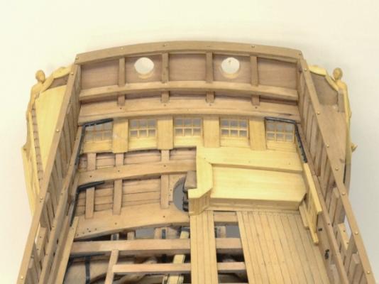
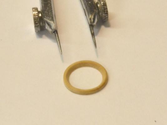
1:60 HMS Naiad 1797 Part 143–Stern Galleries 9– Taffrail Figures Cont. Posted 7/16/12 The work on the stern galleries continues. Progress seems slow. There has been a lot of rework. In the first picture the holes for the two chase ports are finally getting cut. After drilling holes as shown, the rough opening was cut using a jeweler’s saw and the holes were refined to the line on the pattern with files followed by a sanding dowel. The next picture shows the beading for one of the holes These were turned on the lathe from a piece of flat stock glued to a chucked piece with paper between the pieces. The inner diameter was turned first to match the opening and the outer diameter turned to give the width of the bead. At the same time work on the two figures over the stern windows was completed. The two are shown in the next picture picture as they near completion. These are a later version of the same pose shown in an earlier post - with more relief – but they are still friezes, not fully sculpted figure like the quarter posts. They were carved stepwise together to help keep the similar. The next picture shows the second figure being glued to the taffrail. Before this step and after removal from the carving block the carvings were sanded on the back surface to a thinner depth and the back of the figures carved to add some relief. Starting with a thicker carving blank allows for some error and some flexibility in the amount of relief of each part of the pose. This can be seen in the next picture.. The back sides of the head, arm and leg in this view can be seen to be carved back where the meet the taffrail. The next picture shows the inverted model at its current stage. The aft windows of the quarter galleries have be reworked to incorporate a solid panel behind the simulated window grid. This seems to have been the most common practice for these windows. The last picture is another view of the stern at present. The central figure for the taffrail has not yet been added. There is also some additional “gingerbread” in the form of water lily carvings to be added, perhaps some additional bead rails and the name board. Ed


-
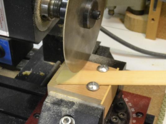
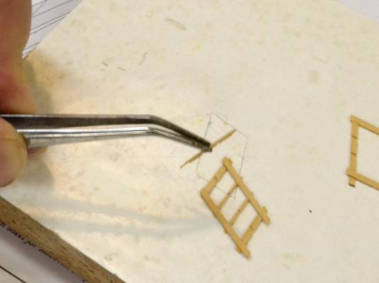
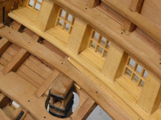
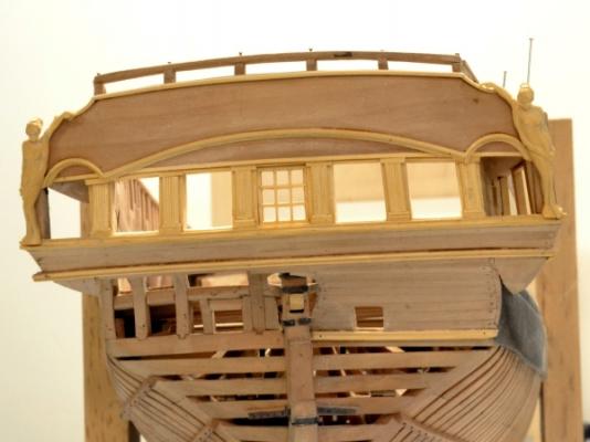
1:60 HMS Naiad 1797 Part 142–Stern Galleries 8–Quarter Gallery Windows Posted 7/16/12 There were some comments on milling the windows. Milling these small pieces, for me at least, was the easiest part of the job – compared to assembling these and fitting them into the window openings. These later steps require a steady hand and that is a problem. The first picture shows the milling setup used to notch the pieces . The slotting saw blade is about 2” thick (.028”). The only one I had of this size was 4” in diameter, hence the oversize blade in the picture. Two-inch thick stock is held down in the jig with two screws with large round heads. The angle is set to the angle of the windows, in this case the quarter gallery windows. A small strip helps keep the wood tight to the jig, but many of the cuts required holding down the piece. Once set up the cutting of the slots was easy using the calibrated wheels to match the 9” x 10” size of the panes. The next step is a bit more fun. The next picture shows a window being assembled. In the next picture an inside grille is being fit into its frame. This was done by sanding the frames until they just fit. The inside grilles were installed deep enough in the frame to allow a second grille to be fit over the glass – a piece of transparency film. In the next picture the forward window with its glass and outer grille has been installed. The outer grille of the second window is fit into place and slight differences between the inner and outer matching grilles are being filed out. Also, a slight bevel was put on the outer mullions at this stage. The outer grille was then removed, the glass fitted and the grille glued back in over it. The last picture shows the finished quarter gallery windows. Ed


-
HMS Victory by EdT - FINISHED - 1:96 - POB
EdT replied to EdT's topic in - Build logs for subjects built 1751 - 1800
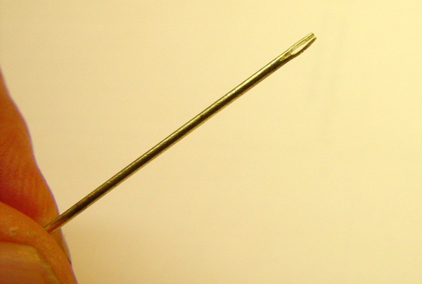
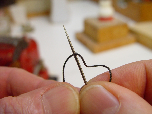
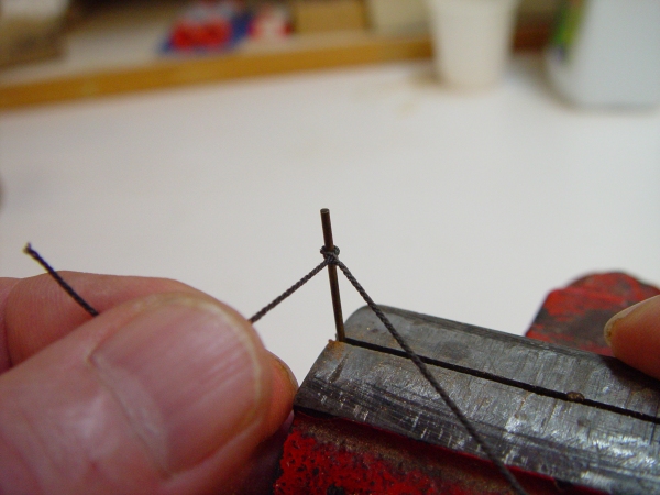
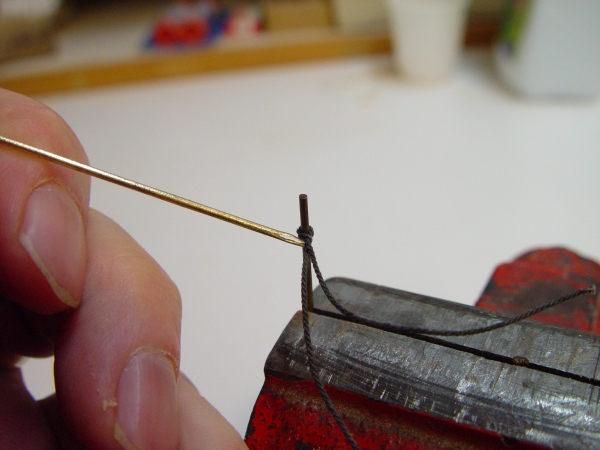
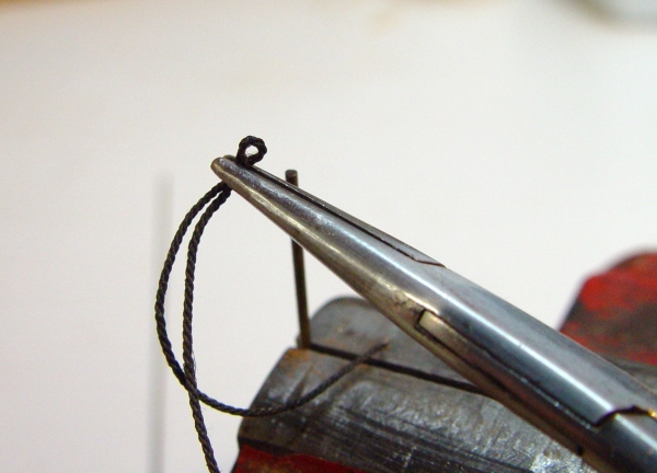
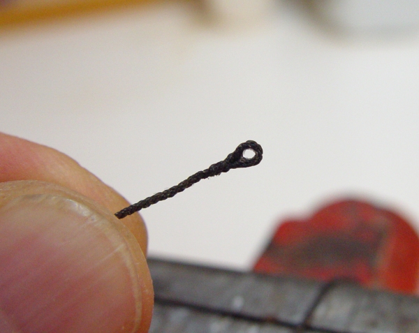
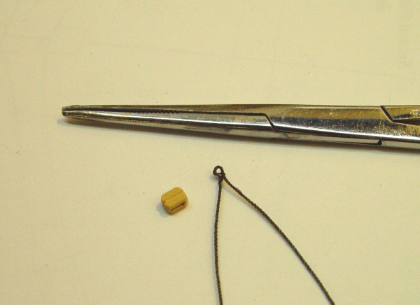
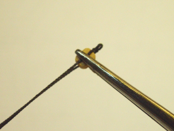
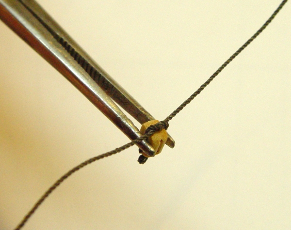
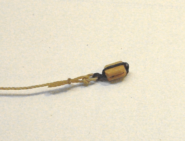
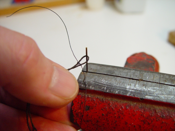
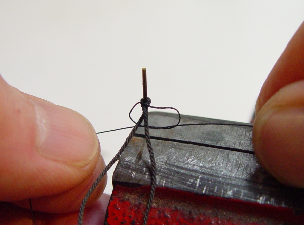
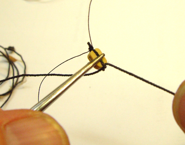
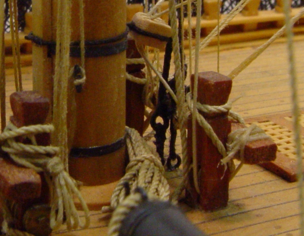
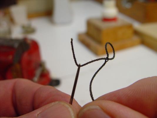
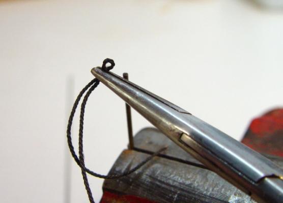
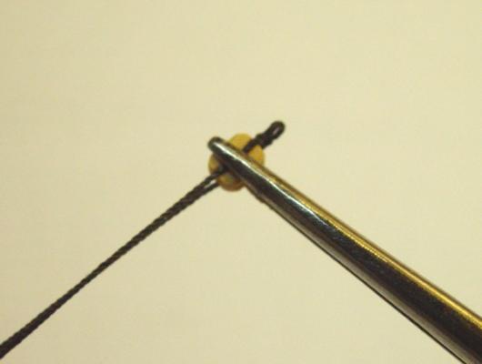
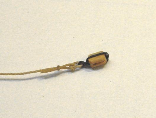
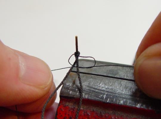
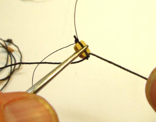
HMS Victory 1:96 Scratchbuild Project Part 18 – Eye Splices and Strops Cyanoacrylate Glue CA glue is one of my least favorite substances to work with. Its difficult to remove from skin, it runs where it is not wanted, its difficult to apply in measured doses, excess can be impossible to remove, it sometimes adheres where desired, but always adheres where not desired. However, I do not believe Victory’s complex rigging, at this scale, could have been modeled very well without it. I once spilled quite a bit of a bottle of this stuff on my workbench. Believe me; that will never happen again. Below is a picture of the simple holder that I always use when using this glue. I do not use the applicator tip on the bottle because dosage can’t be controlled with it and it immediately plugs anyway. I use a homemade brass wire applicator like the one next to the bottle above. A close up picture of the end of this is shown below. To make this, a piece of .030 inch brass rod is slit down one end with a fine blade on a jeweler’s saw, the end is then de-burred and shaped as shown above. The idea is to get it to work like an old style drafting pen, holding a limited amount of liquid. A bit of trial and error is necessary to get the amount it holds right, but it is capable of delivering a very small amount of CA, which is what is needed for rigging at this scale. The applicator is just dipped into the open CA bottle. Two or three of these are needed because they quickly get gummed up. When that happens, I drop them into a tall closed jar of acetone and take out a clean one ready for use. Keeping the jar tightly closed is important. Acetone is hazardous to health and flammable, and the vapors in the closed jar help dissolve the glue above the liquid level. I used the thin grade of CA on all the rigging work. All you really want to do with this is get the rope fibers to stick to one another in a knot or a simplified mimic of a splice. CA was never depended upon by itself. Eye Splices There are relatively very few actual knots in Victory’s rigging. Almost everything is fastened together with spices of some sort, usually eye splices. These were then fastened with seizings or lashings. So, there were very many eye splices to be made. For the very largest lines like the main and forestays, actual splices were made for the model, but that was impractical for anything smaller. So the following process, or some variant of it was used for virtually all the splices. In the first picture below, the rope is untwisted enough to insert a needle, with an eye large enough to take the rope, through the strands. For small, unmade rope, the needle is merely pushed through the center of the thread fibers. The short end of the rope is then threaded on to the needle (which can be pulled mostly through to save rope), and the rope is pulled through itself as shown below. In the next picture the loop has been placed over a piece of stiff wire the size of the desired opening in the eye splice. The short end has then been pulled up tight and the long end has been twisted to tighten up the rope. The short end is then lapped over the long leg and the splice touched with a small drop of CA as shown below. Before the CA has had a chance to completely cure, remove the splice from the wire and clamp it in pliers to give the splice some shape as shown below. The next picture shows the final result after the short leg has been clipped off with scissors. I use small sharp embroidery scissors for this clipping. They, too, need to be cleaned in acetone from time to time to remove CA. Eye splices from large sizes down to the smallest, 1½ inch (.007 diam.) rope were made this way and have withstood rigging tension without any failures. Stropping Blocks There are very many different types of block strops on the model – too many to cover here. Many required some innovative application of the techniques discussed below. Some of the larger blocks, like the jeer blocks, were done completely differently and much more authentically. The following process, or some near variation was used for the great majority of blocks. First an eye splice is made in the rope as described above. For very small lines I just tied double overhand knots to make the loop around the wire post and wet that with CA. In the picture below, an eye has been put in the rope by the method above. Because the stropping process requires at least three hands, the surgical clamp shown below is an essential tool. With the block held between the fingers by the surfaces with the sheave holes, the rope is pulled tight so the splice is down on the top of the block. The rope is then pinched together just below the block with the fingers. The strop is then clamped to the sides of the block with the surgical clamp as shown below. In the next picture the clamp is laid down so the bottom of the block is up. An overhand knot, simulating a splice can then be tied across the bottom. This is then pulled tight and touched with CA. In the picture below the finished block has had the excess rope clipped off and is shown attached to another line with a seized overhand knot, one of the many different ways used, depending on the line. Another method, used on larger blocks is shown below. Instead of the simulated splice, a seizing is put around the rope to form the eye. The eye is then put over the wire as before and the overhand knot in the thread shown above is pulled tight and pushed right up to the wire. A second overhand knot is then added. Perhaps we should call it “an underhand knot,” because it is tied from below to avoid a knot-like appearance. This can be followed by another overhand knot on the top, and so on, depending on the size of the block and how large a seizing is appropriate. A small drop of CA is then applied to the seizing. If the drop of CA is too large in this step, the rope won’t bend around the top of the block. The bottom splice is then applied with an overhand knot on the bottom as shown below. I think we’re getting close to the end, but not quite yet. The next part should wrap it up. Ed Tosti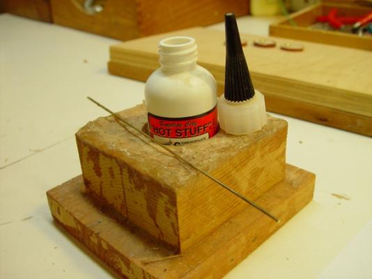


- 57 replies
-
- 12
-
-
HMS Victory by EdT - FINISHED - 1:96 - POB
EdT replied to EdT's topic in - Build logs for subjects built 1751 - 1800
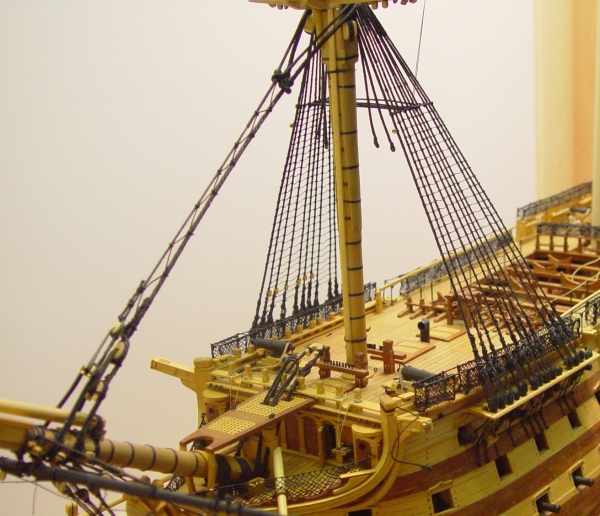
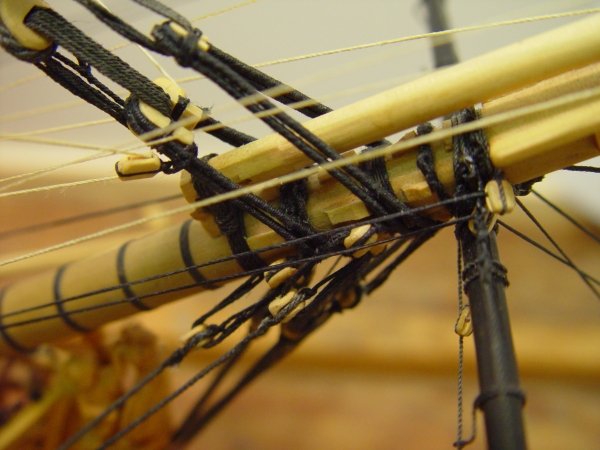
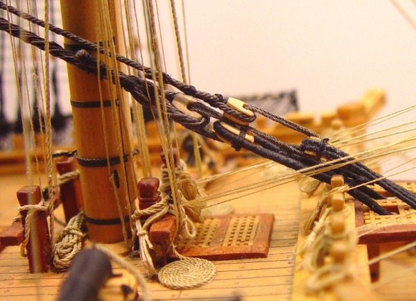
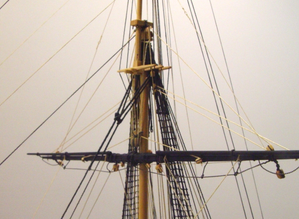
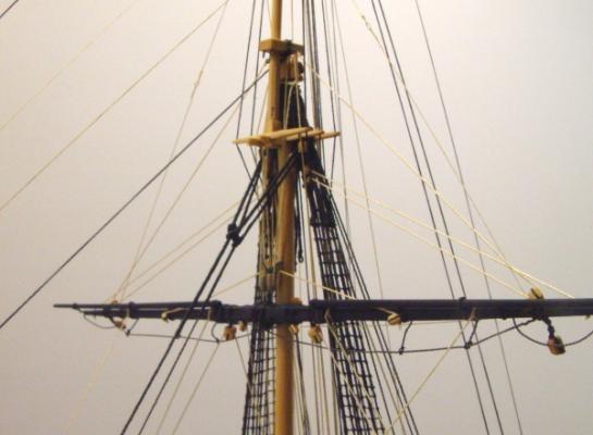
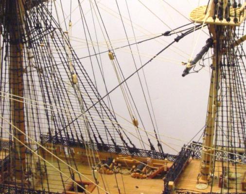
HMS Victory1:96 Scratchbuild Project Part 17 – Stays The stays were principle structural elements of rigging that pulled forward on masts, and the bowsprit to prevent their falling backwards. Offsetting the pull of the stays was the counteracting stress from the shrouds and backstays, and all of these lines kept the masts erect. The picture below shows the fore stay and its smaller backup, the fore preventer stay after installation on the lower foremast. They are tied together with bridging so that strength of either one is not completely lost if it is severed. Both these stays are secured around the bowsprit, which itself is being pulled down by its own stays anchored in the knee of the head, and also by the double banks of gammoning just visible under the marines walk platform. Stays were put over the masthead after the shrouds and were looped over them at the back as shown in the next picture. These loops were formed with a large eye splice that was stopped below the masthead by a large bump in the stay called a mouse. I described how these were made on the model in the section on serving. All these upper parts of the stay were served. At the lower end of the stays are collars, also served, lashed together to from loops into which are seized very large hearts, some open ended, some closed. Between these hearts, one on the stay and one on the collar, a lanyard is wrapped in several turns. This was used to put tension on the stay much in the way deadeyes were used to tension shrouds. A close up of these details is shown below, of both the fore and fore preventer stays, as well as the bowsprit bobstays. Cleats can be seen on the bowsprit to keep the stay collars from sliding backwards. The order of installing all this rigging on the model was, first the bowsprit gammoning – two banks of 11 turns each. This was followed by the bowsprit stays, the lower foremast shrouds, and finally, the lower fore stay and its preventer. This same order was observed in the final tensioning of these lines. After all the tensioning, the bridging was installed. The next picture shows a closeup of the collar of the mainstay. This collar has an eye splice in one end and is served all over. The other end is passed through the grating of the marines walk, through a hole in the port knighthead, underneath the bowsprit, back up through the starboard knighthead and a second hole in the grating, and finally through the eye splice. It is then secured back on itself with lashing. A large heart is then lashed into the collar to take the lanyards connecting it to the mainstay. In the above picture a temporary line is used to as a main stay stand-in to help set this up properly. The following picture shows the final configuration for the mainstay and its preventer. The mainstay is the largest line in the ship, except for the anchor hawsers. In addition to being served at its upper end, it was also wormed over its full length, before serving. This worming can be seen in the upper left corner of the above picture. By the time this stay had been fully tensioned up on the model, there was not much room left between the hearts. Before the model crew puts more tension on the stay, they’re going to have to re-seize the lower end of the stay to its heart, a bit further back. I like this picture because it contrasts some of the largest lines in the ship with some of the very smallest. This next picture shows the main topmast stays, which are looped around the topmast shrouds in much the same way as the lower stays. These are of course, smaller. These topmast stays, as well as the lower mizzen mast stays, run through blocks on the next forward lower masts, or in the case of the fore topmast, through blocks on the bowsprit. The picture below shows this general arrangement. In this case, how the lower mizzen mast stays are routed through large locks strapped to the lower main mast, then down to the deck. It can also be seen here that the main and preventer topmast and lower mizzen mast stays are not parallel or bridged. After passing through their respective blocks, they are lashed to eyebolts in the deck, just behind, in this case, the main mast. The connections for the main topmast stays are shown below, between the bitts and the main mast. I mentioned earlier that my overall order of rigging was first forward to aft, then bottom to top, then standing before running. This meant that all running rigging in this picture was installed before the topmast stays were lashed down. Lashing these stays was the only work that was made significantly more difficult because of the rigging order used. Each lashing took about an hour of work with tweezers, long needles, surgical clamps and a lot of patience. In return for this inconvenience I got unobstructed access behind each mast for all its other rigging, which I believe saved a lot more time overall. In the next part, I will discuss two of the most common rope configurations on the model –eye splices and block strops – and how they were made. Ed Tosti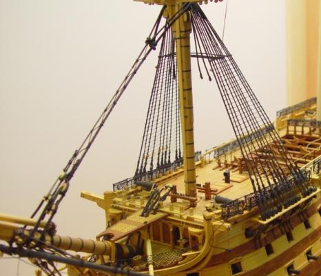


- 57 replies
-
- 10
-
-
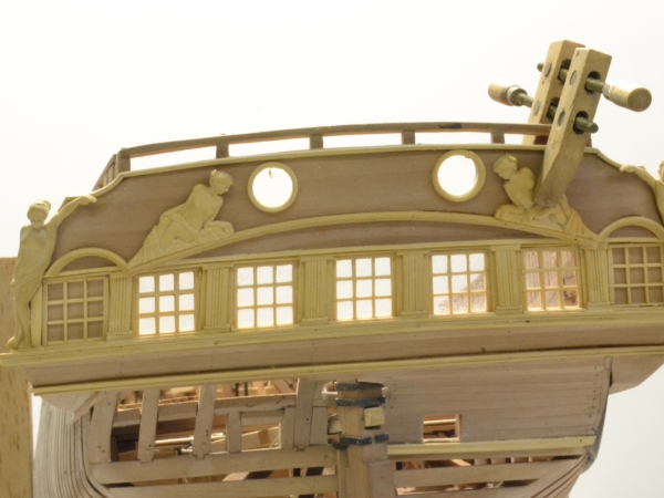
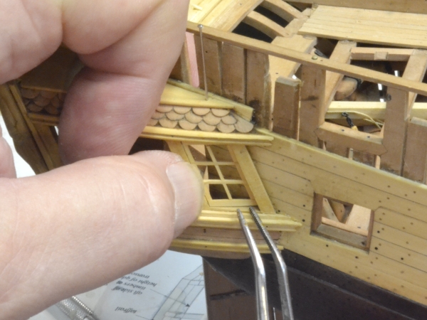
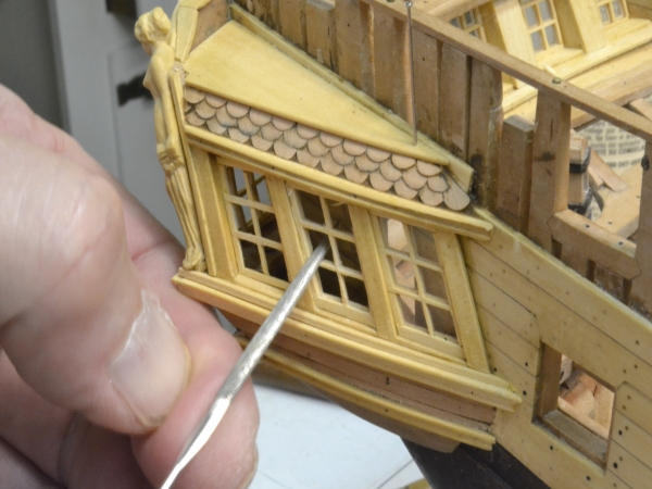
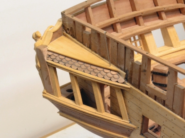
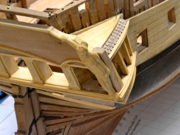
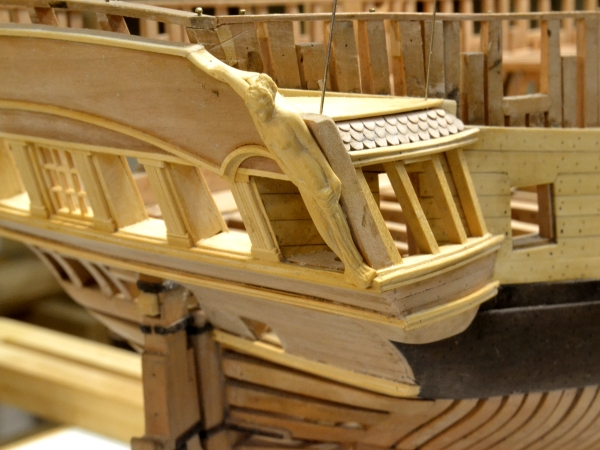
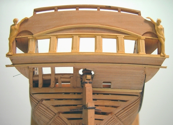
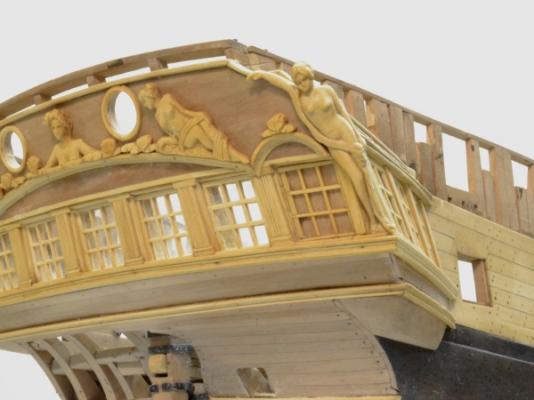
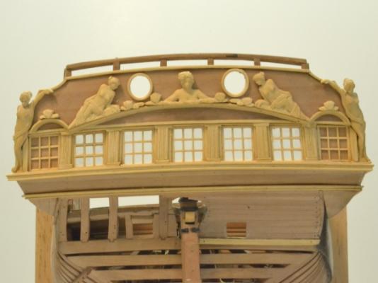
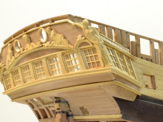
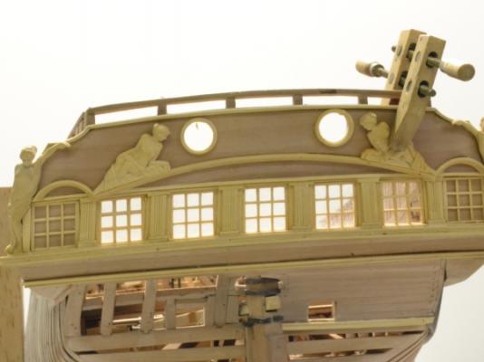
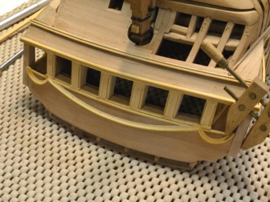
1:60 HMS Naiad 1797 Part 141–Stern Galleries 7–Quarter pieces/Stern lights Posted 7/11/12 With all the excitement over the shingles, which were corrected in the last post, I was evidently distracted enough to install the quarter piece figures incorrectly. I posted the incorrect installation in the last post before realizing that I had installed them on the quarter pieces instead of making them appear as an integral part of the quarter pieces - as I had intended. Senility may be approaching. So, the first picture shows the corrected installation on the starboaed side. In this picture the quarter piece has been beveled off and the figure installed as if it were part of the piece. This was the original plan. The next picture shows another view. In addition to being more correct, the figures look better. They appear to be more upright (as designed) and not falling forward so much due to the angle of the stern. After some redesign and some process development (with some suggestions and help from Keith), I returned to the work on the stern lights. The next picture shows work on the window grilles assembly. The lapped joints were cut with a .028” slotting saw blade on the milling machine, using the calibration wheels to size the 10” X 9” panes, so the mullions are about 2” square. The horizontal mullions are being fixed to the frames first in this picture because the tight fit helps hold the assembly together better initially than the lapped corners would do. The angles of the central five windows could be achieved by angling the frames while the glue was soft. The outer windows and the quarter gallery windows will have their parts milled at an angle. The central window installation is shown in the next picture. The outer grilles were installed first. The frames were sanded to get a tight fit. A thin sheet of plastic was then inserted on the inside and the inside grille fastened over it, so the plastic itself is not glued. (The glass is still hard to keep clean.) The quarter gallery windows will have to be completely installed from the outside – inside grilles first. This picture also shows a pattern fragment pasted to the taffrail to facilitate cutting the chase ports. The next picture shows the windows from a different angle and also the figure on the port quarter piece. The last picture shows the windows from the inside. Ed


-
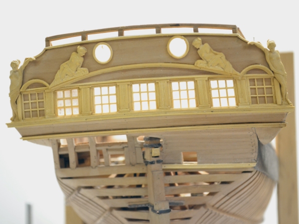
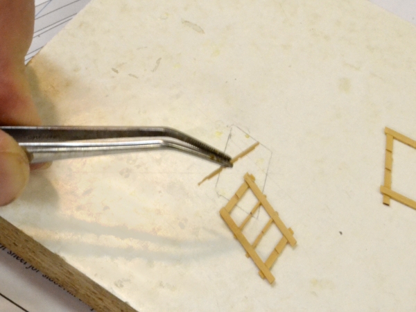
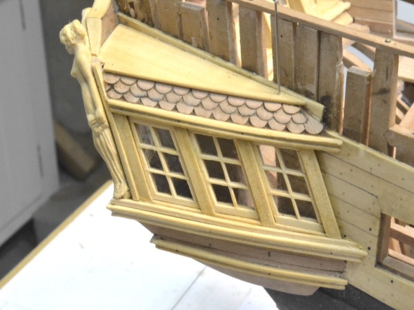
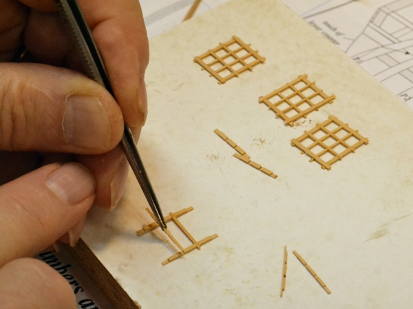
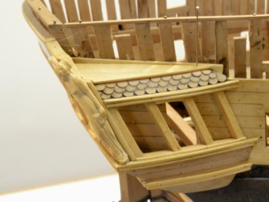
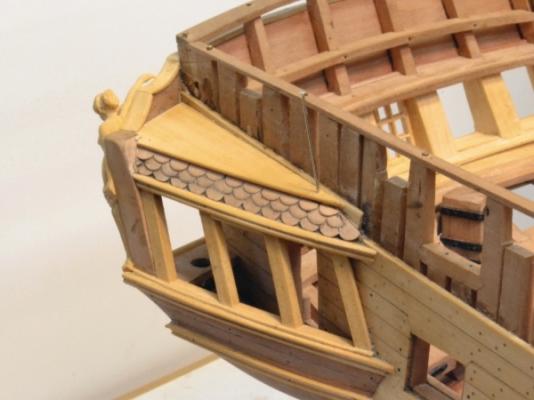
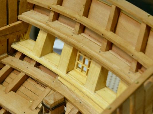
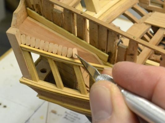
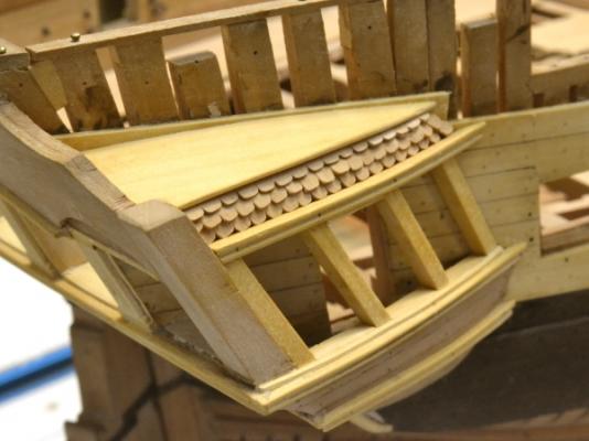
1:60 HMS Naiad 1797 Part 140–Stern Galleries 6–Quarter Galleries/Trim Posted 6/26/12 Comments on the last part convinced me that my shingled roof over the quarter gallery needed to be reworked. I still do not know how these were constructed on the original ships – they may have been lead sheet – but the way they were handled on contemporary models is clear. I decided to mimic that, but still using individual shingles. The new shingles are paper thin and wider. The next picture shows these. There is still a bit of work to do on the front tiles. The decked area above the shingled finishing piece is only pinned at this stage, pending the final cleanup of the shingles. This picture also shows the cap molding fitted to the top of the taffrail and also the permanent attachment of one of the Naiads. The next picture shows another view of the shingles – and the starboard quarter piece Naiad. And one more for good measure. This picture also shows the central stern window installed and more of the taffrail cap molding. The next picture shows another view of the window, the entire cap molding, and both quarter piece Naiad figures. With the figures glued on, the fingers of their raised hands can be carved. Although I tried to give the arms some strength by running the wood grain from the outside foot to the hand, I didn’t want to risk an arm fracture so the detailing of the hands was deferred until the they were fixed in place on the rail. This first window, although glued in, is a test. The window parts were milled so the grid parts interlock and also fit into mortises in the sides, tops and bottom frame pieces. The grid mullions are 1 ¾” square (.028”), so all the notches were dadoed with a .028” thick circular blade on the mill with the pane size and the notch depth set with the mill’s calibrating wheels. The frame was made slightly oversize and custom fit into the windw opening. The window has a thin piece of clear plastic sandwiched between two grids. This can be seen in the next picture. The grids have to be matched. They are also beveled after assembly on the side away from the glass to avoid a squared appearance. The sandwich construction allows them to appear correct when viewed from both sides – but it doubles the work. I can only deal with the fitting of these tiny window parts in small doses, so I am splitting time between that and some of the other work to keep my sanity. Ed

-
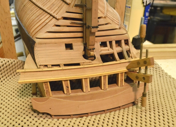
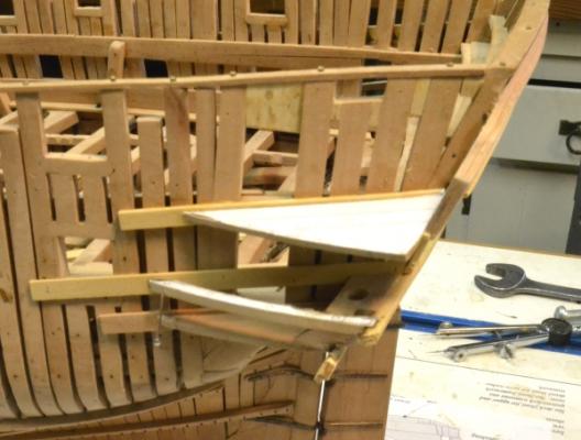
1:60 HMS Naiad 1797 Part 139–Stern Galleries 5 –Quarter Galleries/Trim Posted 6/24/12 The quarter galleries and some trim needed to be installed before moving on to the windows. Before doing that I set the model up on the shipway for some dimensional checks. This is always a good idea, but in this case it was a very good idea, because I found that the upper stools on the quarter galleries were set over a foot too low. So the stools and the construction on top of them had to be removed and scrapped. This also explained why the pieces cut from the patterns did not quite fit in the original installation. I spent some time with the drawings , unsuccessfully trying to solve this mystery. In the first picture the new stools have been installed at the correct height. This was done on both sides This picture also shows the two lower rails and the planking between them installed on the starboard side. The port side will be left unplanked with only the main structural members modeled. In the next picture the window mullions and lower sills have been installed and the upper rail and capping of the lower sills is being glued and clamped in place. The clamping of all these parts was quite awkward. The alignment and spacing of the three window mullions has to be precise or the windows will look odd. This could not be done accurately using the mortises for these previously cut into the lower sill, so after aligning and end gluing the mullions to the stools, they were bolted through the top stool and secured at the bottom by the sills between them and the outer capping being installed here.. The next picture shows this construction after removal of the clamps and pins. At this stage the upper finishing was fit and installed on top of the upper stool. The next picture shows this in place and the roof shingles over it being installed. These were sliced off of a shaped, cross-grain strip with a razor blade. There are three rows as shown in the next picture. In this picture the top and an integral outside molding is being fitted. There will be some fretwork placed on top of this but that will be done much later after completion of the side planking. Trim cove pieces to fit over the quarter gallery windows below the taffrail were made by machining a circular section of molding as shown in the next picture. This could have been turned on the lathe, but the milling machine was used instead with a rotary table. This allowed the same round cutter to be used that was used to make the larger central section of this molding. The next picture shows these two end pieces added to the taffrail. The diameter of these end moldings was determined from the drawing showing the true view of the taffrail. This view was used to make the patterns for cutting out the outer taffrail, so the curved pieces fit almost perfectly – a slight bit of clamping pressure helped on one of them. Ed
-
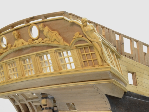
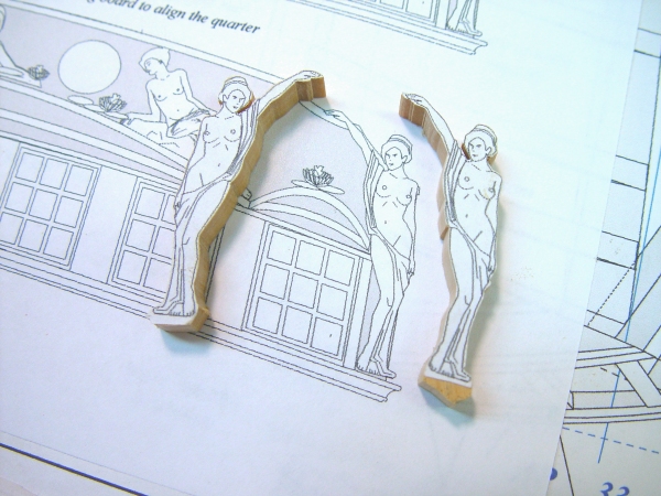
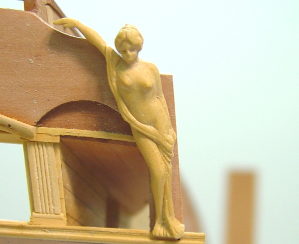
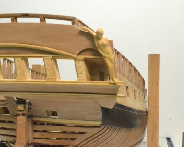
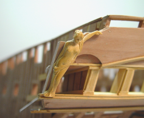
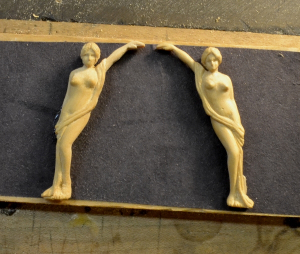
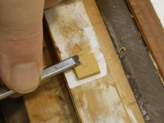
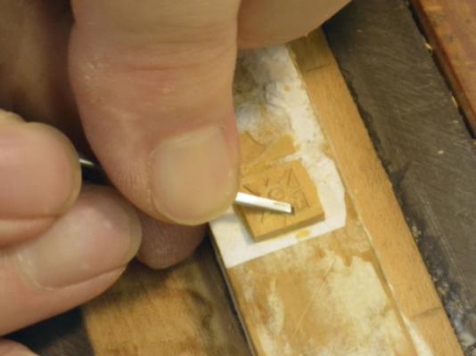
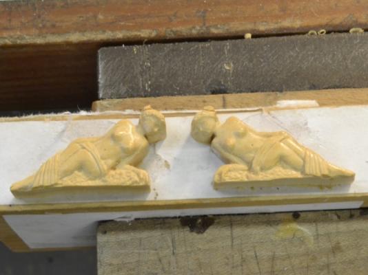
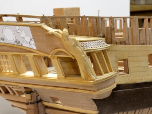
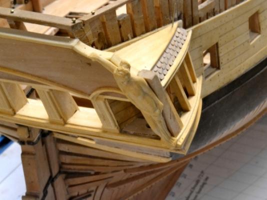
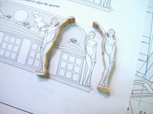
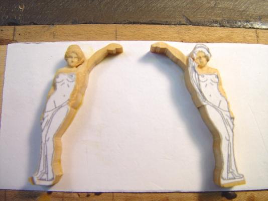
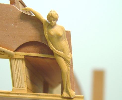
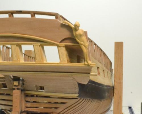
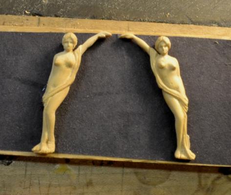
1:60 HMS Naiad 1797 Part 138–Stern Galleries 4 –Quarter Piece Figures Posted 6/18/12 The ratio of hours spent per cubic inch of wood has been skyrocketing lately. The work is still being driven by the necessary construction sequence. As I mentioned earlier, I want to finish all the work that requires the hull to be upside down before returning to the detailing of the quarterdeck, so this meant doing all the stern detailing earlier than expected. The first picture shows the stools and rim for the port quarter galleries being installed. The next required timbers are the quarter pieces, which need to be in place before the quarter gallery windows are done. To do the quarter pieces I wanted to have the quarter piece figures carved so all this could be fit up together. The next picture shows the final (I think) design for the quarter piece figures. Several versions of these figures have been developed and some carved and fit up. In this picture, patterns for the figures for both sides have been pasted to pieces of European boxwood and the shapes cut out on the scroll saw. There is no decoration plan for Naiad, so these figures are speculative. Naiads were fresh water nymphs so I wanted the figures to appear young and graceful. I looked at a lot of 19th century romantic artwork featuring mythological nymphs before settling on a design. In a previous post I showed an early version of the figures to be used toward the center of the taffrail. Those will be redone. In the next picture these have been glued to a wood block with a layer of paper in between to allow them to be removed easily. Carving has begun. The plan was to carve these together to assure that they were at least similar. This approach worked well. I had also made rough mockups of the taffrail figures using epoxy modeling compound. This was helpful in determining the amount of relief needed in various places on the figures. For the final carvings I started with the faces and if they looked Ok moved on to areas that needed to be deep. Both rotary tools and small carving tools were used. The next picture shows one of the figures pasted in place temporarily on the starboard quarter piece to check for fit. The figure is not finished, but the back has been sanded back to fit against the taffrail and post. The next picture was taken at the same time. This picture helps give an idea of the proportions. I resized these a couple of times. There is a cap rail to be fitted on top of the taffrail. The figures hand will rest on this. The next picture shows the figure on the other side being fit in the same way. The next picture shows the stern with both figures further along and pasted in place again. There was a lot of this back and forth. In the last picture the figures have again been returned to the wood block for more detailing and polishing. Hopefully the final refinements on these will get them to a finished state. Once these are installed I will probably move on to all the windows. I’d like to do all these at once – rear and sides. Ed


-
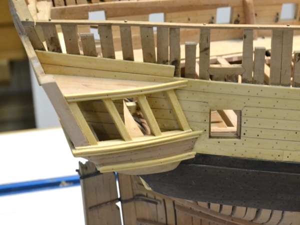
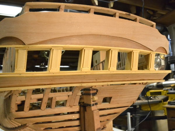
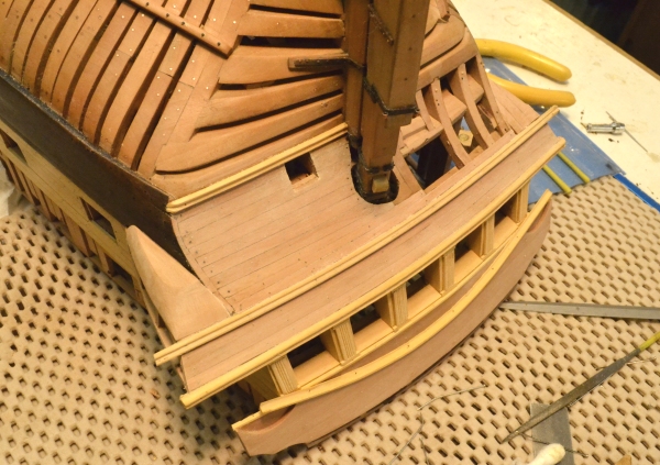
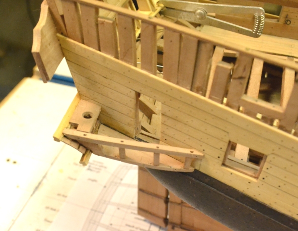
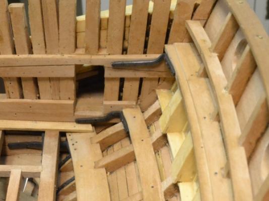
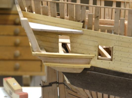
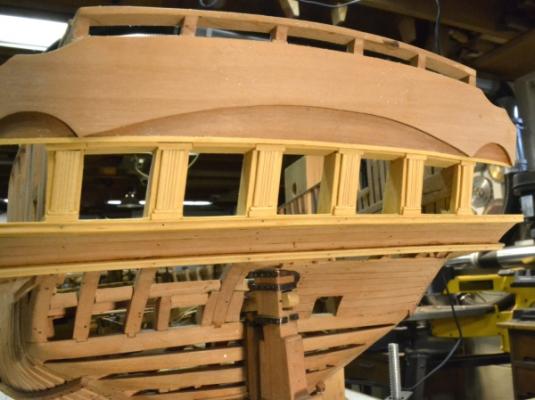
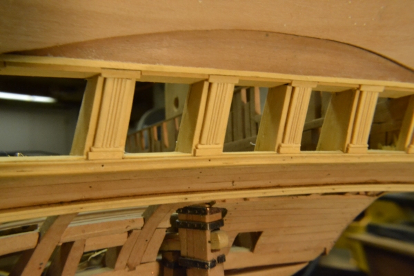
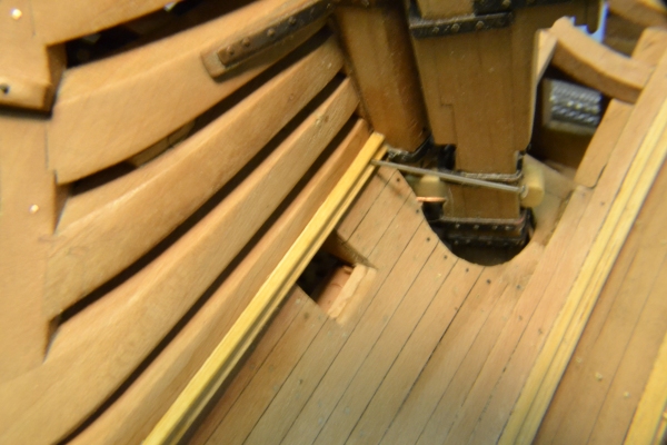
1:60 HMS Naiad 1797 Part 137– Constructing the Stern Galleries 3 Posted 6/10/12 A lot of work has been going on lately, but not too much to show yet. Carving ( and recarving) of the figures for the taffrail has been time consuming. I think I am approaching final versions but nothing to show yet. Sizing has been one issue. However, other work has been proceeding in parallel, but slowly. The first picture shows the exterior decoration of the counter timbers between the windows. The next picture is a closer view. In addition to the columns, top and bottom sills were installed. The window units will fit into these openings. The next picture shows planking of the lower counter being re-installed. Two strakes of this had been removed to install the lower rail. The next picture shows the tuck rail on the staboard side being installed. After forming, this was rabbeted top and bottom to fit over the planking. The lower rabbet is barely visible. This rail will only be installed on this side. The next picture shows the rail and also the lower finishing shaped and fit under the lower stool of the starboard quarter gallery. This picture also shows a cove rail with a bead fitted to the taffrail above the windows. This will be trimmed off at the ends to fit smaller cove rails at the ends. These will most likely be turned or milled using a rotary table – to avoid the sharp curvature needed. The last picture shows the upper finishing being fit above the upper stool on the starboard side. There is still some work to be done on this – shaping the slanted roof and cutting out the notch for the quarter piece. The quarter pieces on each side are large vertical members that are carved on the aft side. These slant back and in. A foot tenon fit in the mortise formed by the pieces at the aft end of the rim and its inside will butt against the taffrail end. I plan to make these in two pieces – the plain forward part installed first and the carved after section which will be attached later. Ed

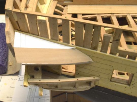
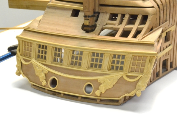
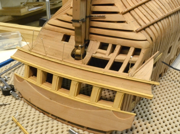
-
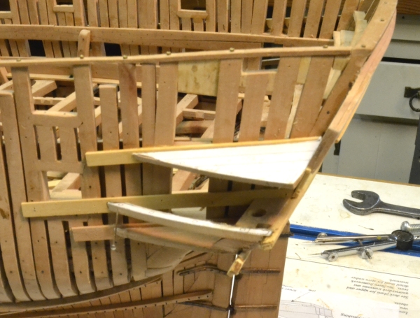
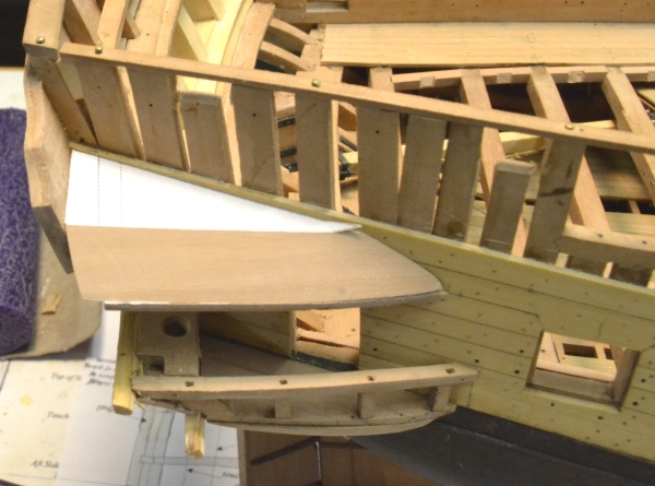
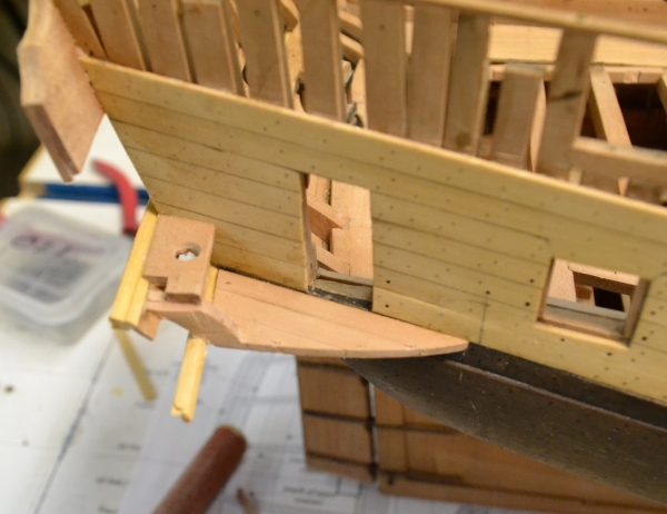
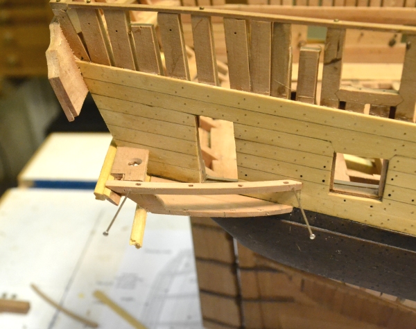
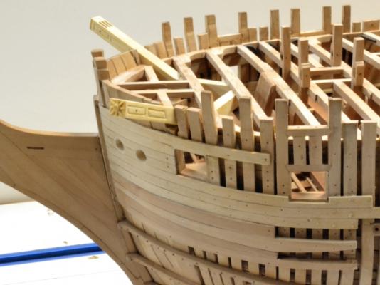
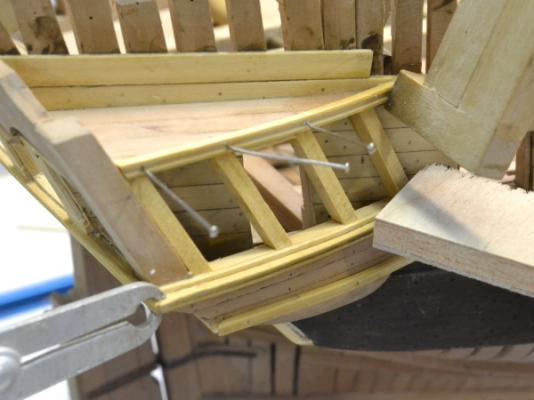
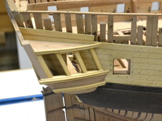
1:60 HMS Naiad 1797 Part 136– Constructing the Stern Galleries 2 Posted 6/3/12 A lot of the work shown below was done concurrently so the pictures are not in strict chronological order. After installing curved blocks for the lower ends of the quarter pieces as shown on one side in the first picture, the next step was to make and install the rims. The rims are curved structural rails that run from the athwartship rail at the top of the upper counter. It rests on top of the lower quarter piece and bolts to the side of the hull just aft of the last port. Pencil marks showing the position at the side are visible in the above picture. The curve of the rims was formed on a wider piece of pear on a form after boiling the piece. In the next picture, the well dried rails are being sliced off this piece using the circular saw. This method assures that the rails on both sides will be the same. In the next picture the starboard rim has been mortised through for the lower stanchions and window mullions and is pinned in place. With the rim positioned the spots for mortises in the lower stool were marked. With the rim removed they were then cut out using a small burr in a rotary tool, then squared a bit with a small chisel. The next picture shows the rim and lower stanchions installed. These stanchions are very tiny pieces and cutting tenons on the ends was a challenge. The aft end of the rim forms the closing side of the mortise for the upper part of the quarter piece, which will attach at the top to the taffrail. The stanchions will be planked over after the counter planking is trimmed back. The counter rails will be cut off at an angle to match similar side rails that will fit over both the rim and the lower stool. The next picture gives a better view of the curve of the rim. This picture also shows the counter timbers boxed in to form the framing of the stern windows. After this, five of the lower window sills were fit into place. One is being glued and clamped in this picture. The next picture shows the sills from above and trim across the front of the timbers. The forward sides of the counter timbers will be boxed over to match the aft sides. This will be done with scored columns with small pediments. A wide bench will be constructed below this on top of the seat transom – the cross member just aft of the rudder.. Most of this finish woodwork was improvised based on the White and McKay books on Diana and Pandora. The next picture shows the completed planking and the rails of the upper counter. Naiad is almost ready for her name. Two strakes of lower counter planking were removed and need to be replaced. There is also a tuck rail to be installed on one side where the planking meets the wing transom. There is a lot of terminology associated with all this, so I hope my descriptions are intelligible. The window top and side sills are not yet installed. The 9-pane window deadlights will be installed within those sills. The specifications call for deadlights, but if anyone can comment on whether sliding sash was used, the input would be appreciated. Cheers, Ed