EdT
-
Posts
2,214 -
Joined
-
Last visited
Content Type
Profiles
Forums
Gallery
Events
Everything posted by EdT
-
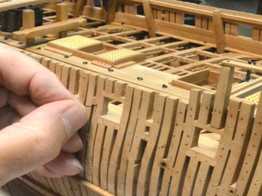
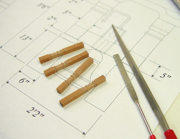
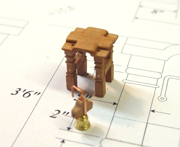
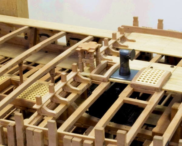
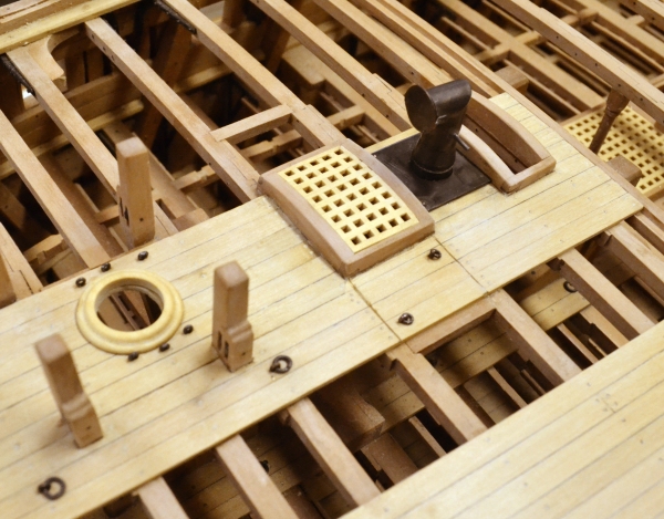
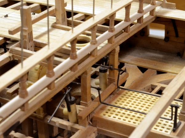
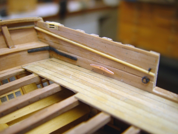
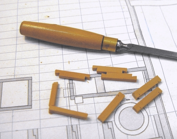
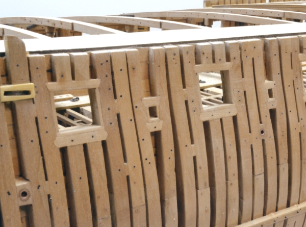
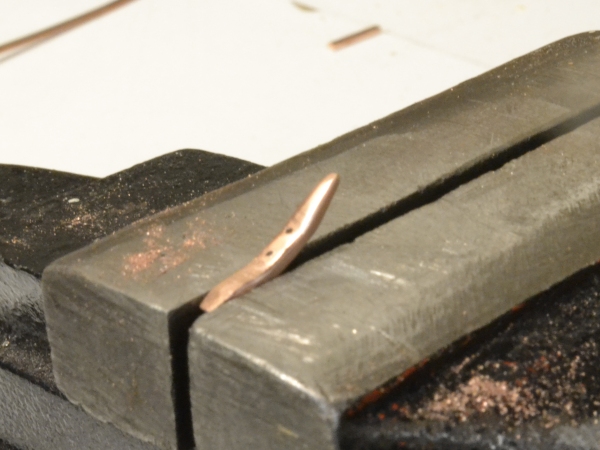
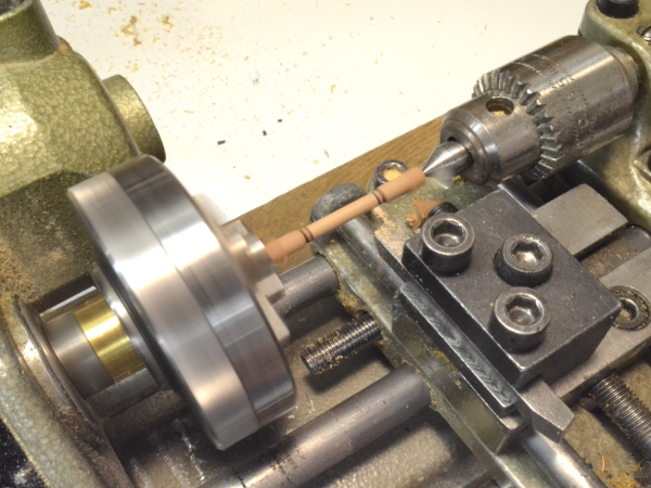
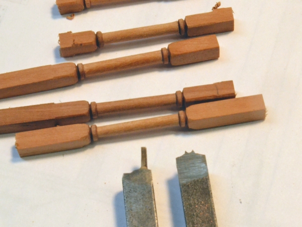
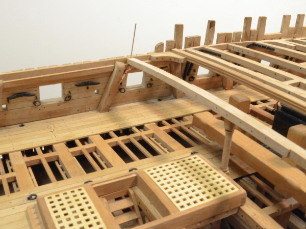
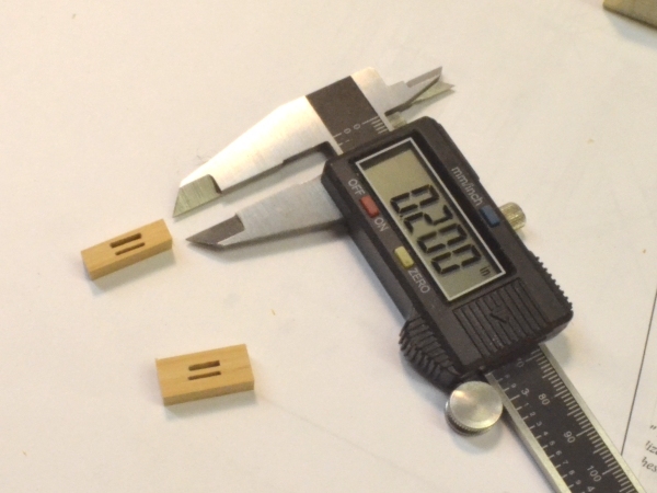
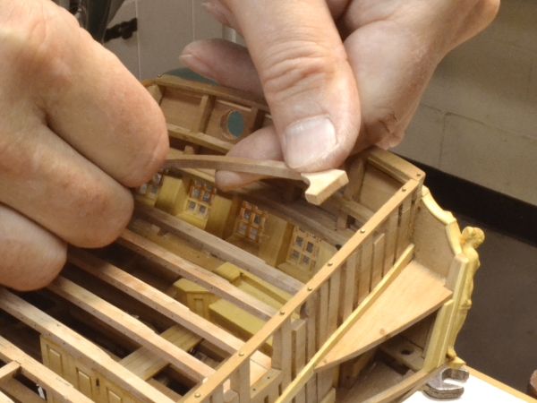
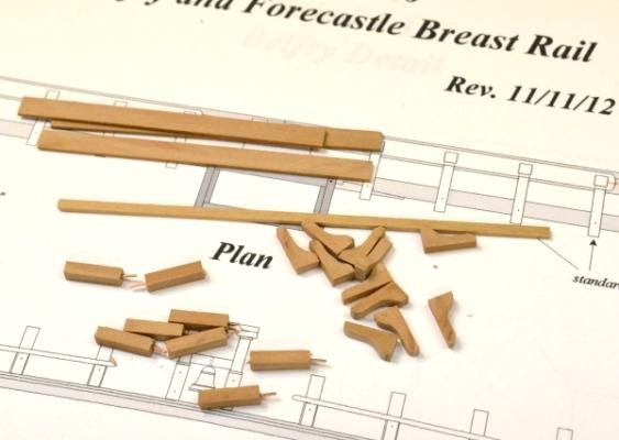
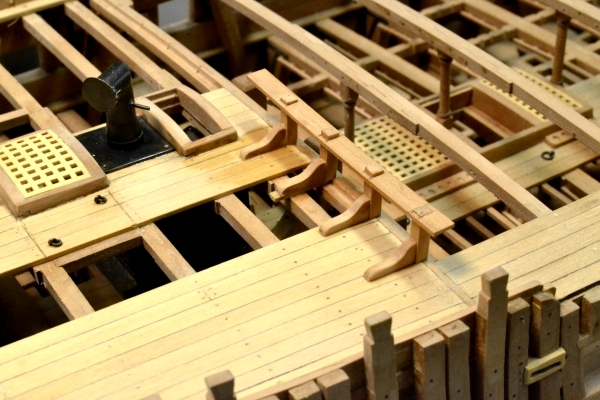
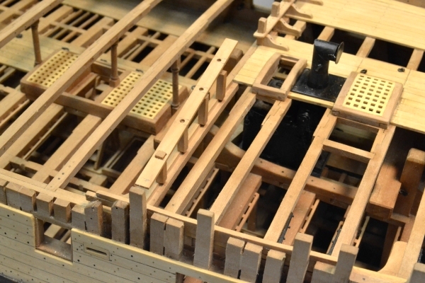
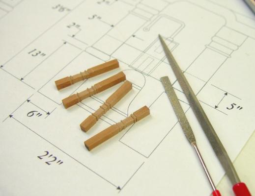
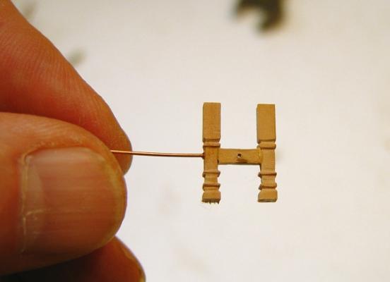
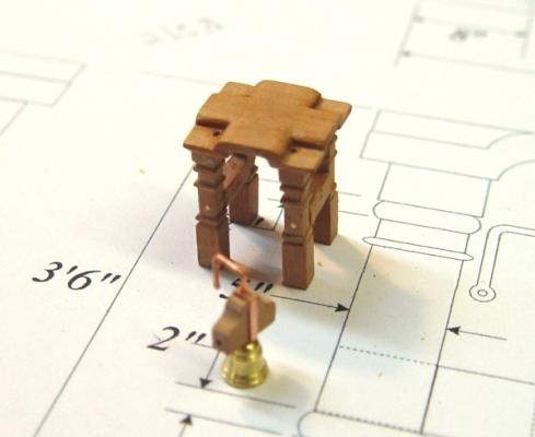
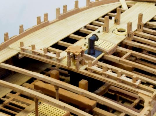
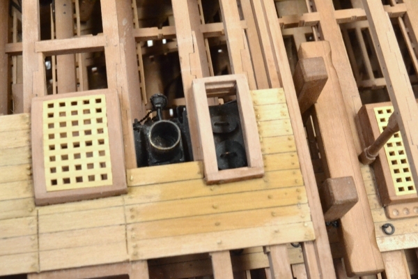
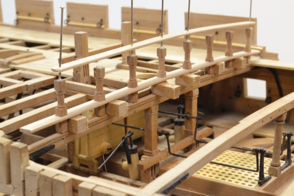
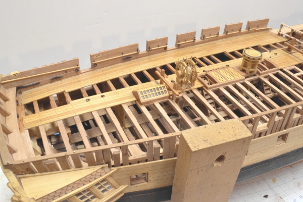
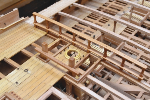
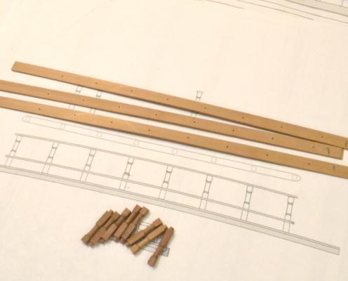
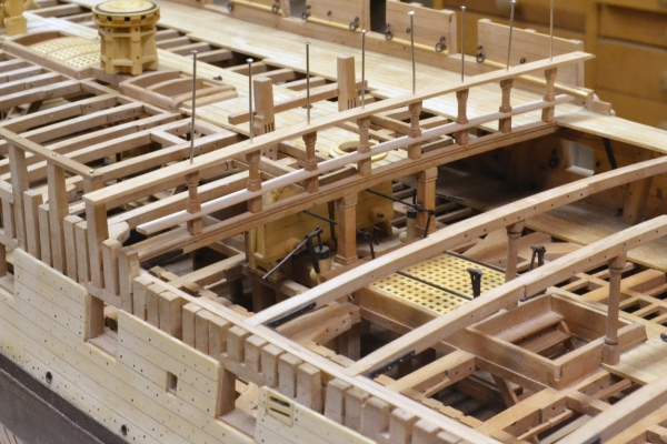
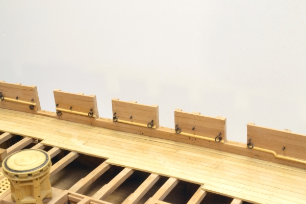
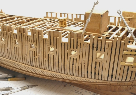
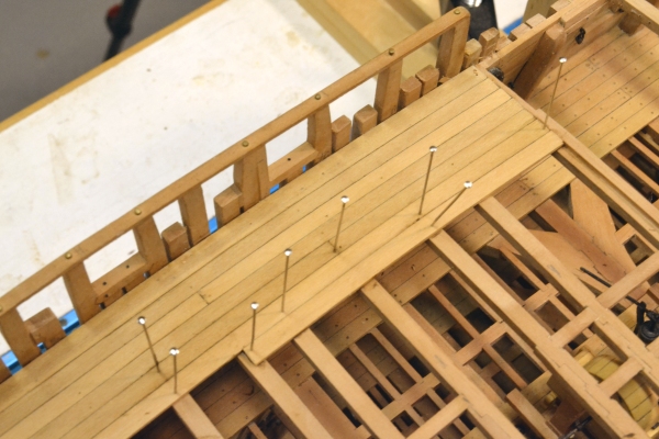
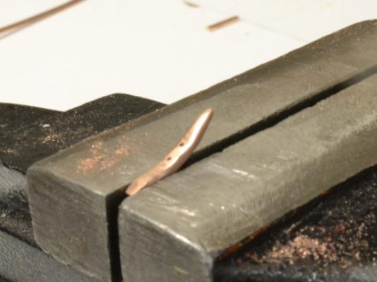
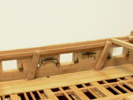
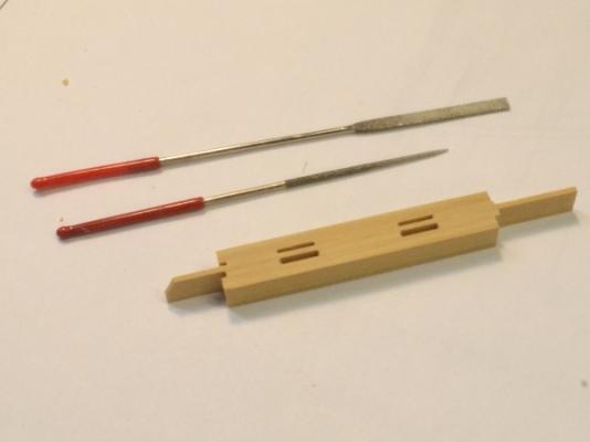
1:60 HMS Naiad 1797 Part 162– Forecastle continued Posted 11/14/12 The parts for the forecastle breast rail are shown below. The long strip in the center will be used for segments of plank under the knees where there is no decking. The next picture shows the stanchions and knees installed on the port side with the rail being used to hold the spacing at the top. When this glue on this has dried the rail will be removed for final sizing and drilling of the belaying pin holes. The next picture shows work on the starboard side. In this picture the stanchions are just pinned in place with small bits of wire inserted in holes in the breast beam. The first through mortise has been cut in the rail and the position of the next one is being checked. The next picture shows the four posts for the belfry – the next task. These were shaped with chisels and files – mostly files of the type shown. But the lines across the posts were first marked with a very fine edge file of the type used to sharpen Japanese woodworking saws. The next picture shows the assembly of one side. The three wood parts were end glued in a fixture to hold the squareness and to keep the sides parallel. As soon as the glue was fully dried bolt holes were drilled on both sides and a wire bolt – as shown – was CA glued into each. These sub-assemblies were extremely fragile until the entire completed belfry was installed. The next picture shows the assembled belfry and the bell mounted on its beam with the ringer handle. The copper parts in this picture, including the bolts through the posts are about to be turned black. The next picture shows the belfry assembled and installed. The four posts are secured into the deck beams with wire pins. This picture also shows the finished breast rails. The next picture shows this area from the forward side. You will notice in this picture that there are no bolts holding the iron plate for the stack. Both the plate and the stack had to be removed to redo the blackening on the brass. Even this picture taken after the re-blackening, shows some brown spots re-appearing. The process used on this second treatment was to remove the wax and first blackening, soak the parts in hot TIVO solution (a pre-plating cleaner), rinse in clean water, blacken in a new batch of dilute selenium solution (Blacken-it), rinse thoroughly in water with dish detergent, dry and buff. Next time copper with liver of sulfur! I am about to reach for the paint can. Ed

-
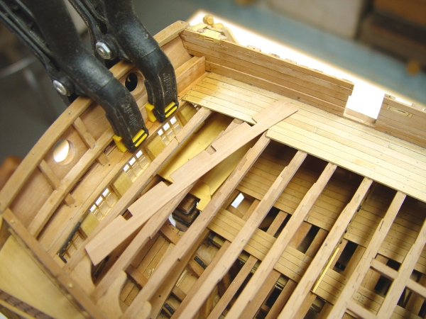
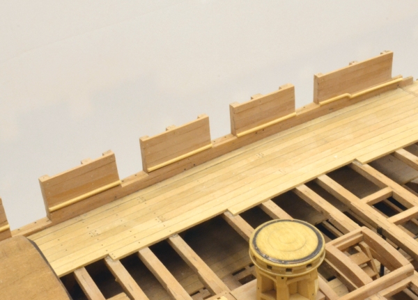
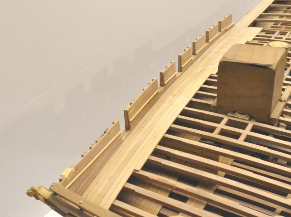
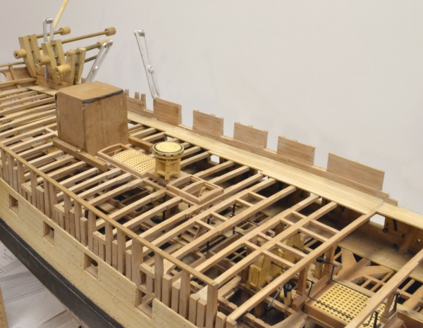
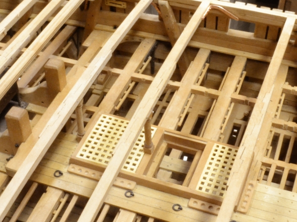
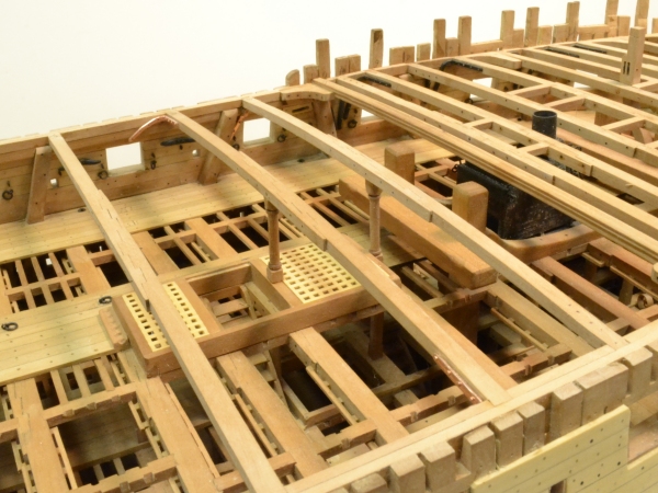
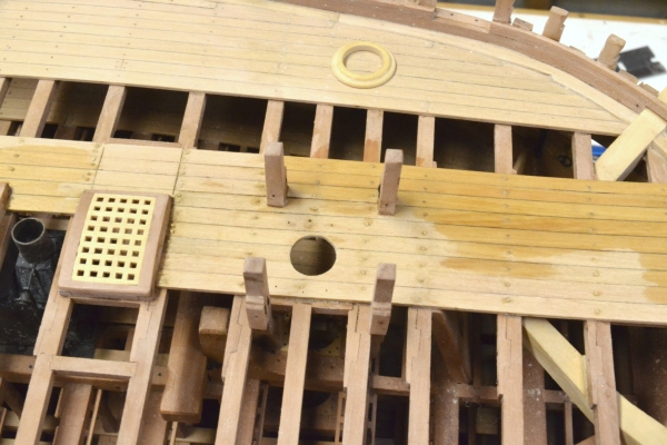
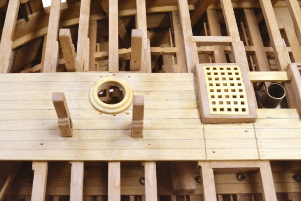
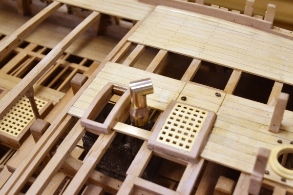
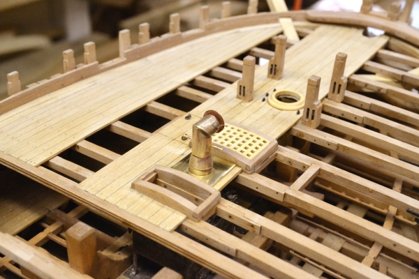
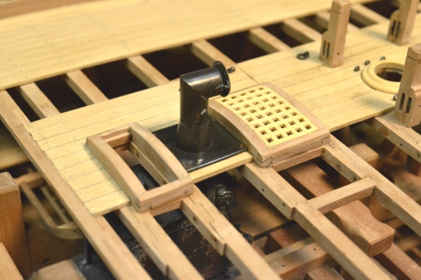
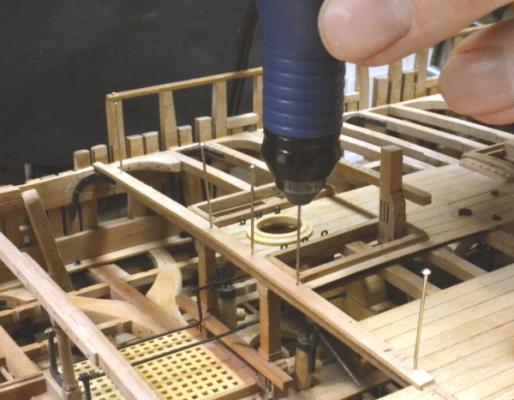
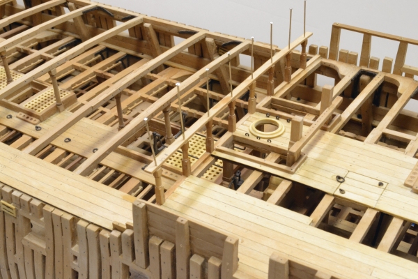
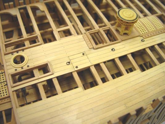
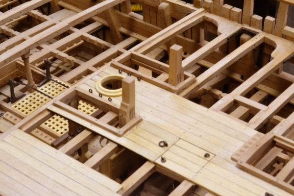
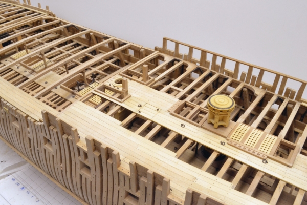
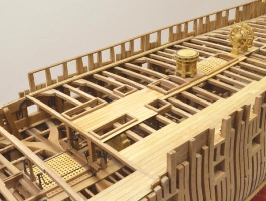
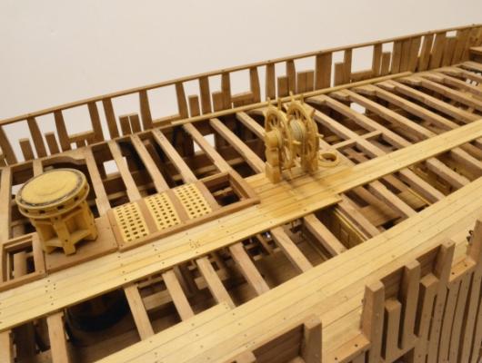
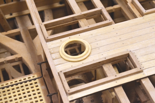
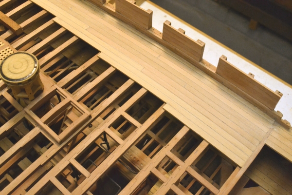
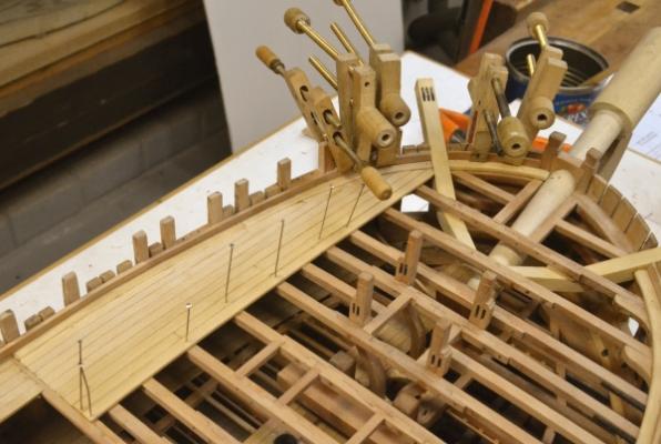
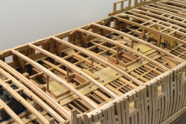
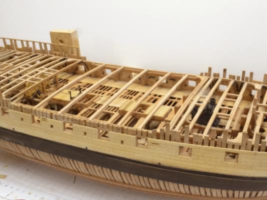
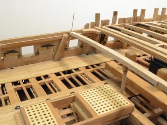
1:60 HMS Naiad 1797 Part 161– Forecastle Posted 11/10/12 The outer planking on the forecastle had been done earlier. The next step on the forecastle was to install the coamings and head ledges for the two hatches on this deck. The first picture shows these. The forward hatch has been fitted with a grating. This hatch is directly over the front cooking area of the stove. The smaller hatch will be left uncovered to show the lids on the two kettles below. The area between these will have an iron plate around the stack to isolate the heat from the wood framing. The scuttle for the top tackles abuts the forward hatch. At this stage most of the decking has been installed and treenailed. The next picture shows more of the decking. In this picture the treenailing has just been completed and parts of the deck are damp from washing off the treenail glue. The hole has been cut for the foremast and the mast ring is waiting to be installed. The next picture shows the full extent of the forecastle decking after all the treenailing, sanding of the deck and installation of the mast ring.. Holes have been drilled for the eyebolts astride the mast ring and for the scuttle ringbolts. The next picture shows a closer view at this stage. In addition to the bolt holes mentioned above, this picture shows the two holes for the gun tackle ringbolts – fore and aft of, and just one strake outside the bitts. In the next picture some of the eyebolts have been installed and the unfinished stack assembly is fit over the stub on top of the stove. The stack was fabricated from brass tubing with a solid turned reducing section that will be just above the iron plate. The three bits of tubing and the solid reducer were silver soldered together. The next picture shows the completed stack assembly and the iron plate. The stack has a baffle plate over its opening and two arms to facilitate turning it. The baffle and its brackets were made from a single piece of .01” copper sheet. The small parts were silver soldered to the stack. The lower part of the stack is brass tubing that telescopes over the stub on the stove. The plate will be bolted to the beams. The next picture shows the final installation with the stack and plate blackened and given a protective coat of microcrystalline wax. The next picture is a view from the opposite side that also shows the ringbolts in the deck for the guns. The breast rails, the belfry, the crosspieces to the bitts, gun ringbolts in the side, plus some final cleanup, sanding and finishing will bring the forecastle up to the essentially finished state of the quarterdeck. Ed


-
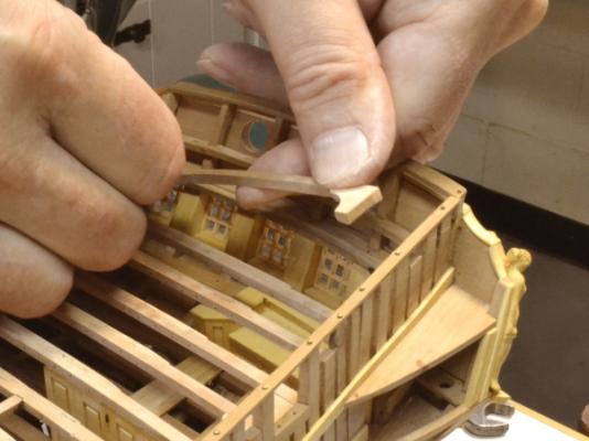
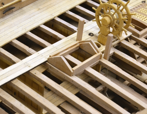
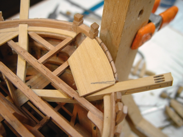
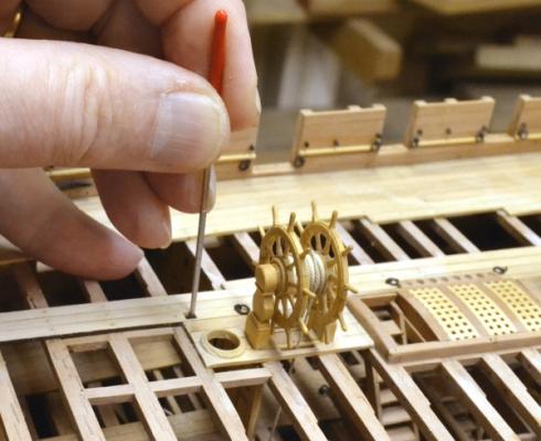
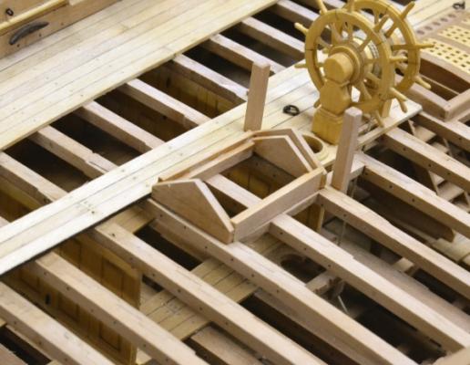
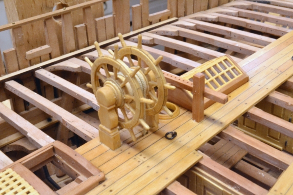
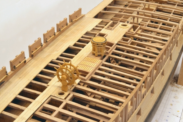
1:60 HMS Naiad 1797 Part 160– Quarterdeck Detailing continued Posted 11/7/12 The first picture shows the top rail of the breast rail about to be glued to the stanchions. Raising the rail on the pins to apply the glue avoids problems of finding the pinholes when they are covered with glue. The lower rail has been glued and its height set by the sized blocks set on the breast beam. After the glue had set on all this, bolts were installed in the top rail and the ends trimmed to size. There was still some work to do aft of the wheel. The next picture shows a hole being cut for one of the bitts aft of the mizzen mast. These features are all a tight fit in this area, but I have followed the profile draft closely. These bitts will be bolted horizonatlly through the beam. I have some little men engaged to come in and install the bolt under the deck below the hole being cut in the above picture. The next picture shows the rough structure of the companion loosely set in place. The bitts are installed in this picture. The companion was built up from eight pieces and in this picture still needs to have these pieces finished off. The next picture shows the mullions and 32 panes of “stone ground glass” installed. The mullion joinery was cut on the milling machine with the spacing calculated from the opening size. The stone-ground glass was simulated by rubbing a clear plastic sheet with abrasives. I assume the ground glass specified in the contract was to diffuse the sunlight and/or provide some privacy. In the next picture the crosspiece to the bitts has been added along with the decking aft of the companion. This picture was taken after application of the wax finish to the port side of the quarterdeck. The next picture shows most of the deck at this stage. Additional ringbolts have been installed in the deck aft of the companion and in the seat transom for the last carronade port and the port stern chase gun. The sides have not received finish. I will do that after the roughtree rail is installed. I still need to make a decision on pin rails. I believe they would have been installed after the Navy took possession and are not in the contract, but I may install them. The last picture shows the completed breast rail with its fresh coat of finish and the completed brace bitt structure.. This essentially completes the quarterdeck. I now expect to work on bringing the forecastle up to the same state. Ed

-
In the above post #159, the astute model shipwright will have noticed that I neglected to cut the sheaves in the bottoms of the breast rail stanchions. I corrected this much later by removing the rail in one piece, drilling and then chiseling out the two very small openings in each post. Ed
-
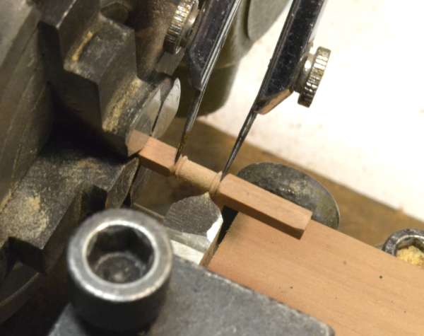
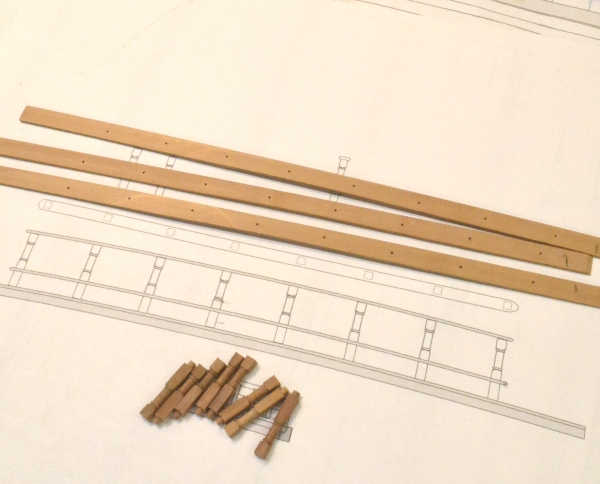
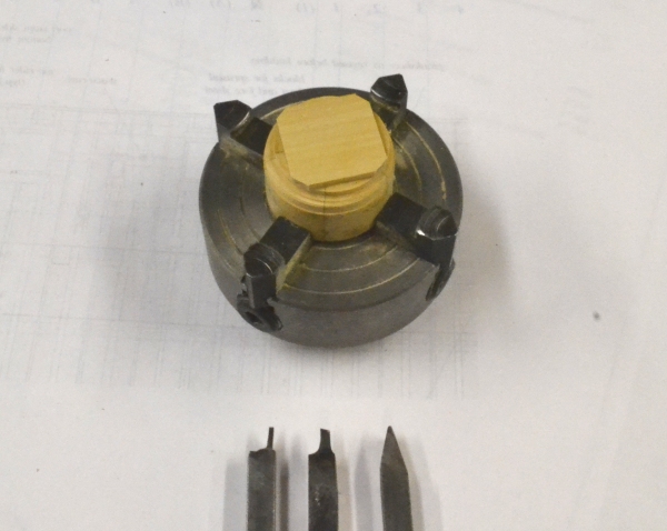
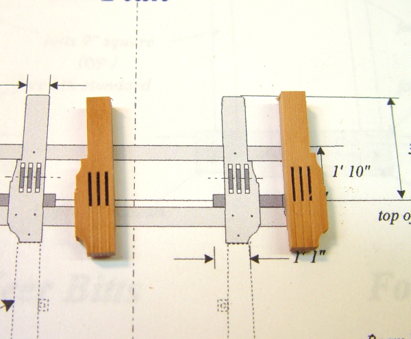
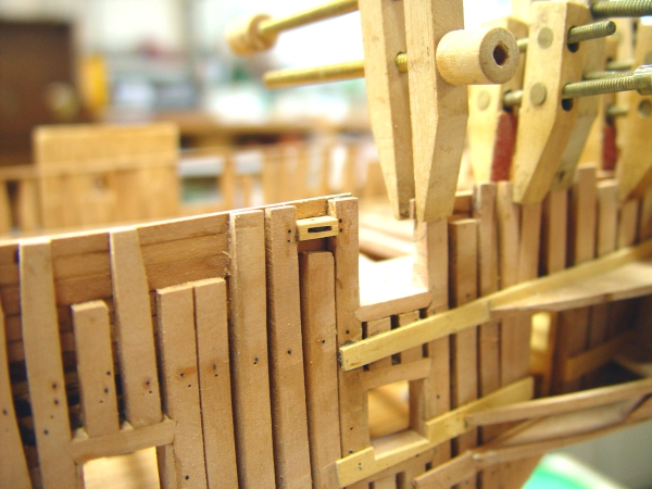
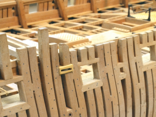
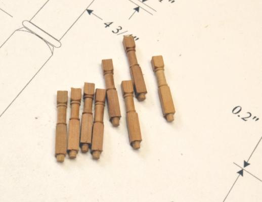
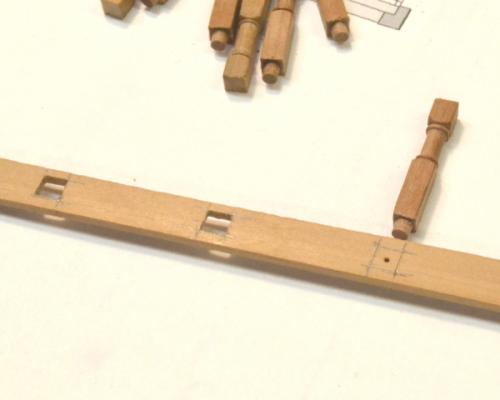
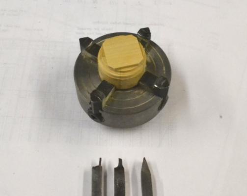
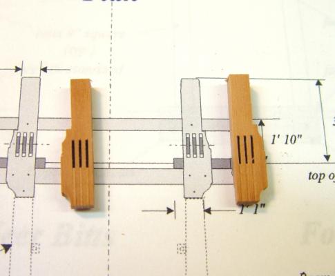
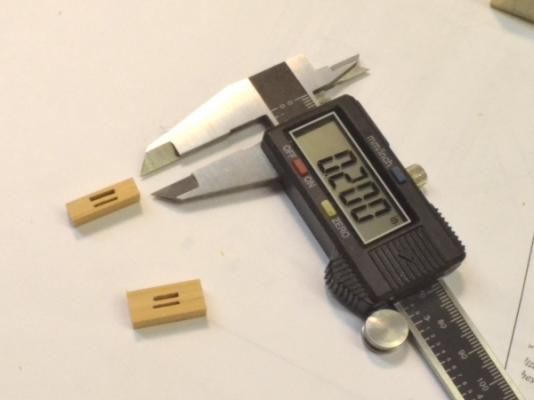
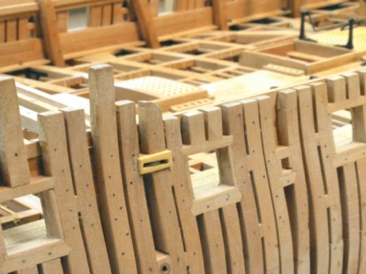
1:60 HMS Naiad 1797 Part 159– Quarterdeck Breast Rail Posted 11/3/12 The breast rail required small turnings for the eight stanchions. These are 5” (.08”) square. The issue with these is to get the round area centered on the square – and to make the turnings reasonably identical in shape. The first picture shows a turning in progress. I began these using a four jaw centering chuck with the opposite end on a dead center, but found that the independent 4-jaw chuck set up as shown in the picture gave more accurate results. Once the first piece is centered, loosening the same two jaws to remove pieces then retightening these on the next piece was pretty efficient and held the centerline well. The length of the turned area was marked with dividers then turned by eye with the tool shown. The next picture shows the final set of stanchions. I turned a dozen or so then selected the most uniform, cut them to length and turned the round tenons on the bottoms in the same lathe setup – but with a square cutter. The next picture shows the stanchions with three blanks for the rails. Two rails are needed. The third is a spare. These are extra wide at this stage. The holes were drilled on center through a thick piece from which the three rails shown were ripped off – leaving identical hole spacing. The drawing fragment above shows the positions of the two rails. The next picture shows the through-mortises in the lower rail being cut. First the square was marked out on the rail around the previously drilled hole. A larger hole was then drilled and the square opened out with chisels and a small square file. One of the other rails was used as a template to drill pilot holes in the breast beam as shown below. These holes were then enlarged to the size of the tenons on the stanchions - manually with a larger bit in a pin vise. The next picture shows the stanchions loosely in place with one of the rails pinned into holes drilled in the top center of each stanchion. The lower rail was fit and removed before this picture was taken. The next picture shows the stanchions glued to the breast beam, the lower rail fit over it and the blank for the upper rail pinned on top – both temporarily. You may notice that this picture also shows the crosspiece of the brace bitts installed and the bitts bolted. This was done following the previous post. The last picture shows the current state of the installation. Having the rails fitted temporarily allowed the alignment and symmetry of the stanchions to be checked after gluing. When the glue sets, the lower rail, which has been sanded smooth, will be raised up to apply glue then slid back into place with spacers on the beam to set the height. It is a tight fit. When dry the top rail will be attached with bolts or treenails. The ends of the rails will be cut off in place. It feels like there should be some knees supporting this structure but I haven’t seen any examples of this. Ed


-
Thank you all very much. I am sorry to have delayed putting the final weeks of work online, but the "reruns" will soon be over and I can do that. Thanks, again. Ed
-
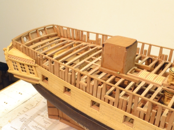
Unfortunately, with all the reposts, the build log has fallen a few months behind actual progress. I just thought I would let everyone know that Naiad was completed yesterday. I will however, continue with the step-by-step build log through the completion. There are about 15 more reposts to do first. Below is a picture of the finished model, returned to where she began, on my drafting table - off my workbench and out of the shop for the first time in over three years. It looks empty in there without her. Right now the workbench is being put to use on her case. Ed ps. The "bunker" over the wheel will come off later, just before she enters the case - or maybe for some photos.

-
Robert, Most of the eye and ringbolts are made from 22 gauge wire and virtually all of the knee bolts. When stretched until breaking, the diameter is about .022" which equates to just over 1 1/4" at 1:60 scale - about right for the stopper ringbolts in the deck, slightly large for the gun hardware. I probably could have used 24 gauge for those (.018" stretched). I used 20 gauge for the main and fore chains and their preventer eyebolts. Those are more like the specified 1 3/8" (.028"). Ed
-
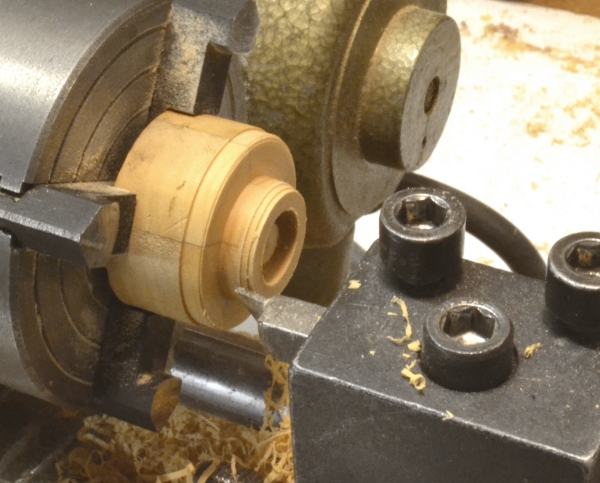
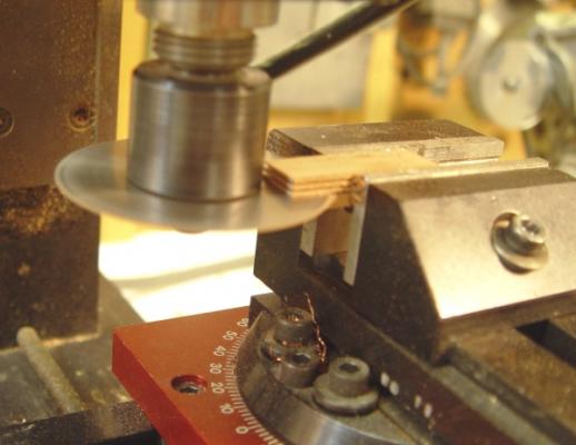
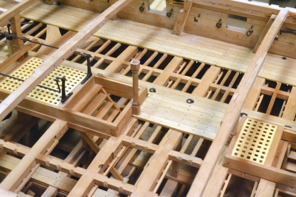
1:60 HMS Naiad 1797 Part 158– Quarterdeck continued Posted 10/31/12 Still working on the detail on the quarterdeck. There was a question after the last post on the process for turning mast rings. The first picture shows the set up for this and the tools used. A flat square of European Boxwood about the thickness of the ring was glued directly to a round block – actually a leftover from turning the wheel or maybe the capstan. The next picture shows the piece in the lathe. The bore was turned first using the boring tool in the center of the top picture. Here the outer diameter. is being turned - back far enough so the ring can be parted off. The curve is then cut with the rounded tool on the right in the first picture. The ring was given its final shape with files then sanded and polished in the lathe with steel wool. The scuttles for the top tackles were revised after some comments on the last post. The coamings were removed and a planked hatch installed on the port side as shown in the next picture. This picture also shows some of the deck ironwork. All of this has now been installed. The next picture shows the fore brace bitts before installation of their sheaves. The sheaves in these are less than 2” thick so I was stuck for a process to make square openings that small. I first made these by laminating the entire piece but the laminations were too pronounced, so I decided to saw out slots from the bottom and fill these up to the sheave openings. The joints can be seen above, but will be much less noticeable at the bottoms of these when installed. The next picture shows the cutting the slots. The three slots are being cut with a .023” slotting saw blade – very slow speed and very shallow cuts to avoid burning the wood and really accentuating the laminations. Thin pieces were then glued in. The very thin sheaves were turned to their diameter of 9”, parted off with a x-acto knife, sanded to fit the slots, then dyed and installed. The next picture shows the two bitts in place. These will be bolted to the beam and the main jeer bitt pins below – when the glue has set. The next picture shows these from the forward side. The cross piece will be added later. Two length of shot rack have been installed. One is visible in this picture. The last picture shows more of the quarterdeck. The ringbolts outside the hatches are for the guns. The other shot rack is also visible. Small ringbolts were installed on the top tackle scuttle hatch. Except for some features aft of the wheel, the quarterdeck is pretty much finished. Ed


-
There is an error in the above post #157. On the hatch framing, the ledges are set down over the coamings, not as I have shown. A common error that nailed me as well. The head ledges were bolted into the beams and thus able to hold down the coamings. Coamings in the fore and aft direction would have to be bolted to carlings and these were not bolted down, but merely drivein down into the scores and presumably held down by the deck planking. Anyway, fear not, all this was corrected in the detailed method described for making these in Volume II. Sorry, if anyone was mislead by this. Ed
-
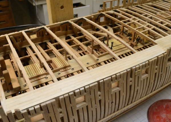
1:60 HMS Naiad 1797 Part 157– Quarterdeck/Forecastle continued Posted 10/24/12 More work on the quarterdeck. The first picture shows the ironwork in the side for the guns. These were made with 22 gauge copper wire. The rings were silver soldered, so selenium blackening agent was used instead of liver of sulfur, which does not etch silver solder very well. The next picture shows the seat transom iron knee and one of the two cleats fitted to the sides on this deck. The next step was to install the framing of the openings for the rigging hatches astride and behind the main mast. The next picture shows some head ledges and coamings while their joints were being cut. The pieces toward the top are coamings. The next picture shows the four openings framed. There was some guesswork here. Some contemporary models show no framing. White’s book on Diana shows them framed. Framing made sense to me, so these are framed like the other deck openings. In the next picture the decking in this area has been installed. The “bunker” over the wheel has been removed to allow the planking on this deck to proceed. The next picture shows the planking around the wheel back to the opening for the companion. I decided to fit the companion up to the decking this time. Seems easier. In the next picture the hole for the main mast has been cut and fitted with a turned ring. The three holes on each side are for eyebolts. All of the installed planking up to this point has been treenailed and sanded smooth. The next picture shows the extent of the progress at this time. While exposed, the wheel has gotten another coat of wax – hence the pronounced color. This will dull down as it dries. The fore brace bitts need to be installed in the two forward openings astride the mast. I now have the drawing of these finished so that work can proceed. That and the companion are probably the next steps, then the eyebolts and ringbolts in the deck. Getting close to being finished on this deck. Ed


-
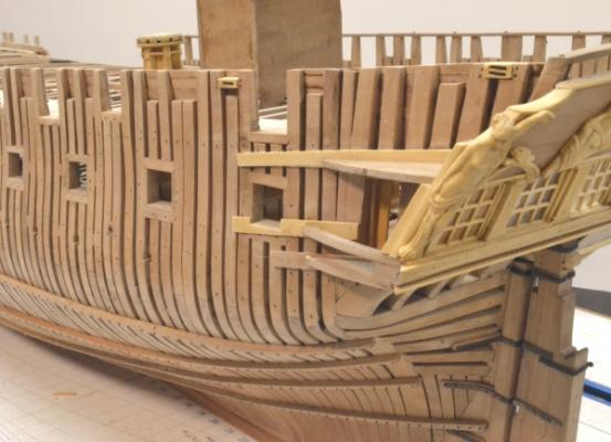
1:60 HMS Naiad 1797 Part 156– Quarterdeck/Forecastle continued Posted 10/19/12Fleshing out of the inside planking and related details on the weatherdecks continued this week. The first picture shows the forward section of waterway on the starboard side in the process of being shaped to fit the curve of the side. I do not normally make templates when spiling pieces like this but prefer to work directly on a wood blank. The forward curve was shaped on the disk sander – by trial and error. The crude pencil mark shows where the piece will be cut to clear the cathead. When the forward edge and the ends fit neatly, the width of the plank will be marked off parallel to the front edge and cut to yield the final piece. The next picture shows the bow after the above piece plus the spirketing over it had been installed – followed by the breast-hook-over-the-bowsprit. This latter piece is 9” thick by 13’ long and fays to the top strake of the spirketing and the knighthead assembly. It has 12 bolts through the bollards. In this picture the port side timberheads have been given a preliminary shaping. The next picture shows the quarterdeck seat being installed. Detailing of this seat required some speculation. The space behind the seat transom would most likely have been sealed off to prevent water from running down the taffrail into the captain’s cabin, so I decided to install this in the form of a seat on the transom with a closed panel in the front. The front is being glued on in the picture. The top of the seat is also shown in the picture. It was made to fit tightly around the counter timbers and to the taffrail. This picture also shows the two fixed blocks in the side installed – one just ahead of the last carronade port and one just forward of the taffrail. The next picture shows the outside of one of these blocks. The aftermost top strakes of internal planking are being installed in this picture. The bolts securing the fixed block have been installed. There is still a fair amount of cleanup to be done on the exterior in this area and I still need to decide on the extent of the planks under the quarter gallery structure to leave in place. I may remove the forward ends of these. The next picture shows the inside of these blocks and the finished seat. In this picture the side has been completely “berthed up” to the tops of the timbers with 2 ½” thick planks above the 3” thick spirketing. This picture and the next two also show the decorative trim rail installed along the inside planked area. Following the line of the top external drift rail, this rail would have been at the top of the side planking if the quarterdeck were not berthed up. This internal trim may or may not have been installed when quarterdeck sides were berthed up in the original construction – but I decided to include it. Tradition often dictated installing details like this that preserved the appearance of earlier designs. The next picture shows the full line of this trim. Although it may be hard to discern in these pictures, all the side and deck planking treenailing is finished. Some ironwork now needs to be installed – the ringbolts for the guns in the sides, the seat transom knees, and a pair of iron cleats. I am also considering installing two cavil blocks on this side of this deck. Installing of the roughtree rail at the top of the side is becoming a temptation. The last picture shows the exterior framing in this area after some finish sanding. It also shows the two fixed blocks with their bolts. The Naiad on the port quarter piece and her four companions are getting impatient with the progress of the work – pretty boring just standing around for all these months. Cheers, Ed


-
Thanks, Remco. That is the same one I found. Maybe I will get a chance to use it on my next project. Ed
-
Remco, One search and I found it. Fox Champion Cup burs. Worth a try. Thanks, again. Ed
-
Remco, That is a very interesting cup bur. Does it have a name. The problem I have with the ones I use is that they quickly plug up with copper and stop cutting. Yors looks interesting. I will look for it. Thanks, Ed
-
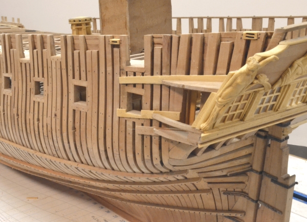
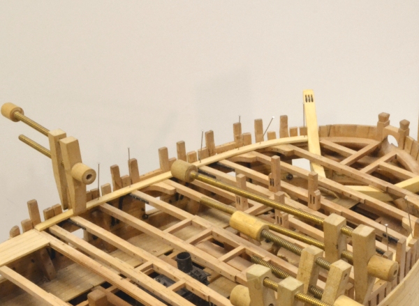
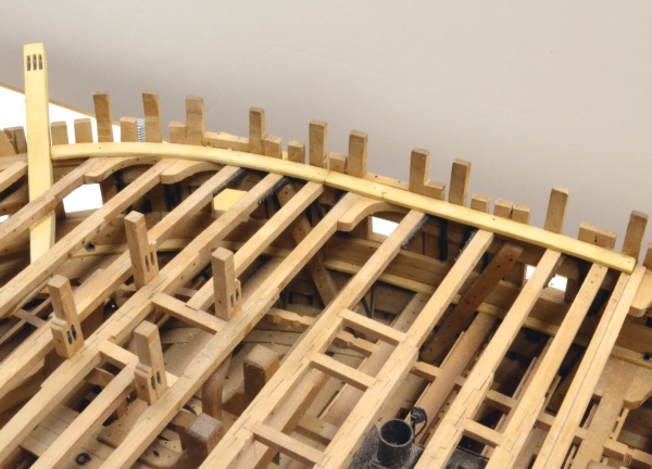
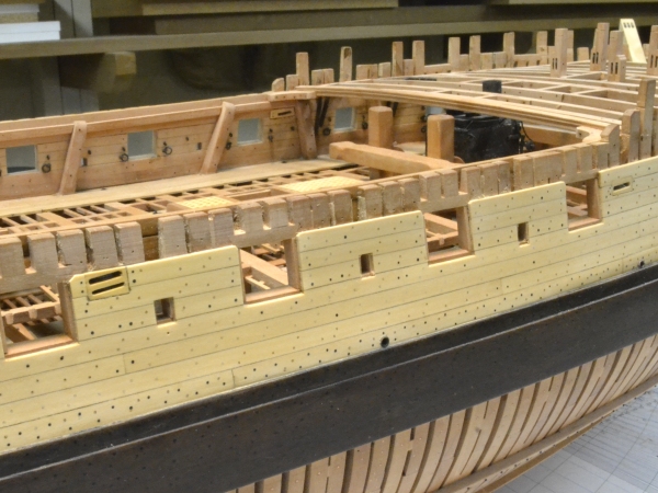
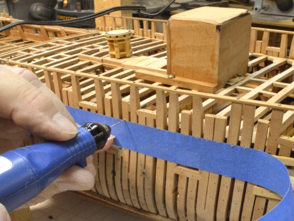
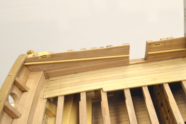
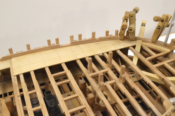
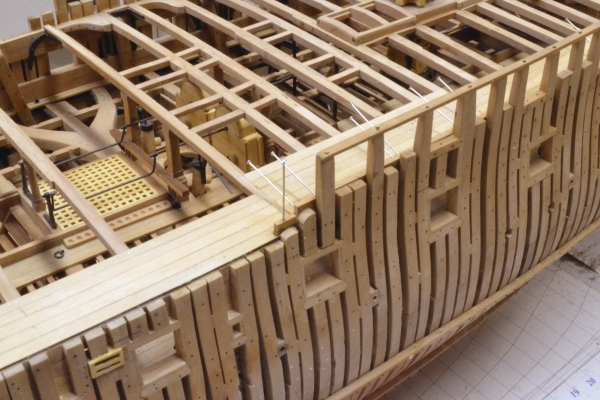
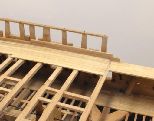
1:60 HMS Naiad 1797 Part 155– Quarterdeck/Forecastle continued Posted 10/14/12 Work has been moving forward at a good pace on the decking and the inside planking of the quarterdeck and forecastle. The first picture shows the spirketing and the “berthing up” of the qdeck well along. The temporary roughtree rail has been removed but saved as a drilling template for the final rail. There are still a few strakes of decking to be added to the outside planked area on this deck, and of course the decking in the center area, which is awaiting the framing of the numerous hatch openings. The top strakes of side planking aft will await the installation of the fixed blocks on the aft framing. I will be glad to dispense with the unsightly bomb shelter – but not yet. I have whacked it several times already. The next picture shows the berthing up from the outside of the hull. This side will be exposed as shown but some ribbands and of course the roughtree rail will be added. The next picture from above shows the decking leveled out and rough sanded. The three ports in this picture are 9-pounder ports – open up to the roughtree rail. In the next picture the waterway on the forecastle is being glued down. The forward end of this piece was curved into shape by my usual method of boiling, pinning/clamping it in place, allowing it to thoroughly dry, then finish sanding it and gluing it down. The next picture shows this on the starboard side. In the next picture two sections of the lower strake of spirketing on either side of the cathead are drying after boiling. The aft section is glued in. The decking of the forecastle has been going on concurrently and is all installed in this picture. Although difficult to discern in this picture, the five outside strakes are “hooked” at their forwards ends with the fifth hook cut into the waterway. The remaining inside planks are angled at the end to fit the waterway and cathead. The waterway between the cathead and dummy bowsprit and the strake of spirketing above it are being installed in this picture. In the next picture the next strake of spirketing has been installed up to the aft side of the forward carronade port and the forward section is clamped in place and drying out. In this picture the planking has been leveled out. The lines of nail holes have been marked for drilling. The next picture shows the same status on the starboard side, but there will be no decking on this side. The aft carronade port sill on this side is a bit low – another error due to premature port framing. Fortunately both sides of this port will be planked over so the repair will be hidden. Otherwise, the match in heights of the topside and the breadth of the spirketing band on both sides matches up. Only one of the timberheads required some surgery. They should finish up pretty well. I have been concerned about this since these frames were installed – over two years ago. I did not want to have to use short dummies for these. The hole marks in the decking can be seen in this picture. Ed

-
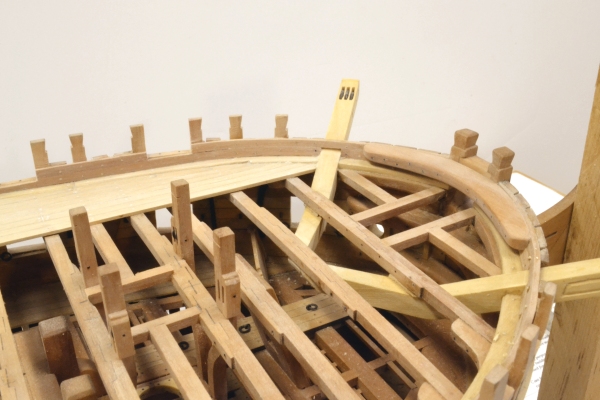
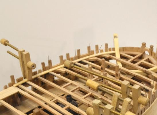
1:60 HMS Naiad 1797 Part 154– Quarterdeck/Gangway Posted 10/10/12 The installation of the skid beams was completed this week. The first picture shows a pillar for the next to last beam. The beam is mortised to fit the tenon on the top of this pillar, which is also tenoned into the center plank at the bottom. Each of these pillars rests on top of a beam. Where necessary the bases are cut back to fit against the head ledges of the hatchways as shown in the picture. The next picture shows all of the skid beams installed . . . . . . . . and thus, finally all the deck beams in the model. This was the last of them and the last of the fabrication of iron knees – a major milestone. The next picture shows the beginning of the quarterdeck planking. All the planking at this level is 3” thick. The waterway against the frames is 4” thick, 11” wide and bearded down to just above the top of the next plank.. The planks are being set with a 3-butt shift with a minimum of 6 feet between butts, except that I am avoiding short planks at the ends. The next picture shows the gangway planking installed. The plank butts here are given less shift to keep the planks long, given the wide spacing between beams. The 3” thick planksheer will fit against the outermost plank on top of the frames so it will be flush with the gangway decking. It will extend outward beyond the side planking enough to allow a round molded edge. In the next picture the first strakes of spirketing are being installed. The top corners of these forward ends will be cut back later to match the curved ends of the drift rails. The tops of the frames have been roughly cut back to this shape. The next picture shows this area from the inside. In this picture the decks have been leveled out. The ends of the gangway planks fit into a rabbet cut into the front of the breast beams, similar but not as wide as the rabbet for the qdeck planks. I may be a bit ahead of myself with the top strake of spirketing. As installed its top is at the height of the 9-pounder port sills, but I need to do some research to discover if these ports had linings. If so the top strake will need to be raised to match the lining top. These are currently drafted with no sills. Any opinions? The last picture shows the outside of the frames in the waist area. I believe all of the bolts are installed except for those securing the two large cleats inside. The frames need to be finish sanded before installing the planksheer. This is well along on the frames to the left in this picture. Pinholes above the ports from the temporary ribbands that were removed earlier are still visible. These will be covered by a permanent ribband like the one just visible in the lower right corner. There will also be one in between. When all the finished sanding and buffing is done the copper scuppers shown in this picture will be blackened to simulate lead. At this stage of the work, the accuracy in the placement of the heavy structural members meets the intricate detail of the finish carpentry – and the inaccuracies in the former start to come home to roost. A lot of dimension checking has been going on this week. Cheers, Ed


-
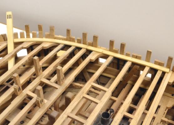
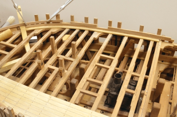
1:60 HMS Naiad 1797 Part 153– Skid Beams Posted 10/4/12 There are two large cleats to be made and bolted to the side in the waist before installing the overhead beams. These secured the lines that reeve through the fixed blocks discussed in the last post. These, like the iron structural knees, were made from copper electrical wire – in this case 12 gauge. The first picture shows one of these during the final shaping process. The next picture shows a pair installed on the port side. The next picture shows the five skid beams positioned on their clamps over the waist. Each of these will be secured at the ends with a single iron knee – much like the other beams at this level – but these are spaced further apart. The contract language had not quite caught up with the practice of permanently installed skid beams flush with the fore and aft decks at this level, so some assumptions were made in deciding how these are secured as well as there spacing. These were placed over upper deck beams to allow a pillar to be installed under the center of each one. They are the longest beams at this level and would be pretty “springy” without pillars. In the next picture a pillar is being turned from a strip of pear. The piece is turned at high speed – secured in a four jaw centering chuck with a dead center being used to steady the other end. There is no four-jaw centering chuck for the Unimat, so a brass adapter was made to use the Sherline chuck. This is visible in the picture. The next picture shows some turned pillars before sizing. The two tools used to turn these are shown in the picture. The next picture shows the first beam installed with its iron knees and pillar. The next picture shows the first two beams installed from above. The last picture shows the same two installed beams. This picture shows chocks fit between the beams – similar to those used with the iron knees in other locations. There are a lot of obstructions on the side planking in the waist and fitting the knees was something of a challenge. The curved side mounted knee shown in this picture is typical of most of the skid beam knees – of necessity. Installing the remaining three skid beams should be straightforward. This will complete the last of the deck beams – a total of 115 for all the decks. Not exactly a three decker, but a lot of work to check off as finished. Ed


-
Welcome back, Revier. I have missed seeing your lovely woek and especially your very creative methods. Thanks, Ed
-
Hi Allan, The laminated approach certainly gives yo a clean opening. I find the joint lines are not very noticeble - I use Titebond on Euro boxwood for these. I also used this method on the lower ends of the fore brace bitts, which have very narrow sheaves - and on the catblocks as well. Both these methods are discussed in Volume II. The brace bitts are also covered in Part 158 which I have not yet reposted. Ed
-
Druxey, The riders are shown on the original profile that is dated before the contract was let (Sept 1795) and there are located to avoid beams and ports. With just these obstructions, some of the fits are tight. I do not believe there are any as-builts for Naiad. There are no fixed blocks shown on any of the drafts, so the interference problems I referred to are not original drawing errors per se. They arose from problems trying to locate the blocks roughly where they belong while avoiding ports, main frames, riders, chains, etc. but the riders were the main obstructions. I should have seen this earlier on my own drafts, but by the time I added the blocks and some other details like that to the drawings, the rifders were already installed - a problem with just in time drafting. On the final revisions for the book, adjustments have been made, but some of the locations are tight and normal construction error may still cause some problems. I would be very surprised if the shipwrights didn't confront this problem routinely. Ed
-
ancre Le Fleuron 1729 by rekon54 - 1:24
EdT replied to rekon54's topic in - Build logs for subjects built 1501 - 1750
Extraordinary work as always, rekon. Beautiful. Ed -
Very interesting process on the copper bolts, Remco. Thanks for posting. Ed
- 1,215 replies
-
- 1
-

-
- sloop
- kingfisher
- (and 1 more)
-
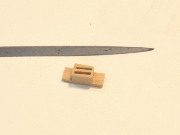
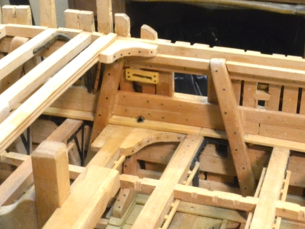
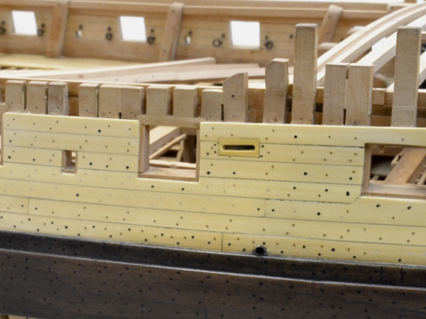
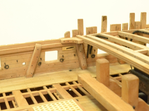
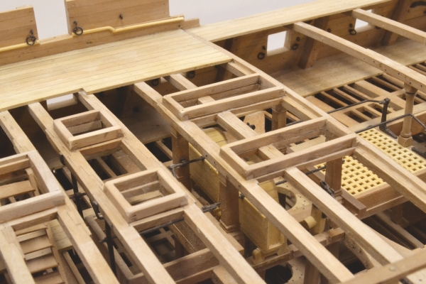
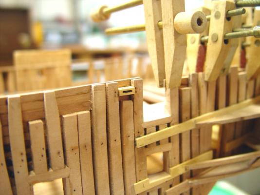
1:60 HMS Naiad 1797 Part 152– Fixed Blocks Posted 9/30/12 Before installing the skid beams in the waist, some details need to be added. These include on each side a fixed single block for the main tack and a double version for the fore and spritsail sheets and iron cleats for these lines. I will also install turned pillars under the skid beams. All this work has been proceeding concurrently for the past few days. I will cover the blocks in this part. These were assemblies that were bolted from the inside through a lap joint inset into the internal planking with the outside of the block flush with the outer planking – as will be seen below. Steel gives quite specific dimensions for these including the bolts through the laps. The first picture shows the way I made these as a sandwich of built up strips. The very small sheave thickness of 1 ¼” for the spritsail sheet block dictates this approach. I just don’t have a milling bit that small – or long enough. The sandwich approach also leaves very clean and precisely sized openings. The first picture shows an assembly from which both blocks will be cut. The files are to remove glue residue and round the ends a bit. The next picture shows the first of these sized to the correct depth of 12”. The sheaves slant downward somewhat in the aft direction. After facing off the slant on the top, the bottom face was cut to size by ripping on the circular saw. The next picture shows a double block casing. The lap ears still need to be trimmed to size. Sheaves of the correct diameter and thickness were turned from pear and dyed almost black. I believe these would have been made from lignum vitae – a dense, oily, dark, tropical hardwood. Pins were inserted in drilled through-holes – but not until the block casing was fit into the side and trimmed on flush on the outside – just before final installation. Two small holes for ¾” bolts were also drilled in each ear – also after fitting. All this was the easy part. I won’t go into all the gory details of cutting the openings and fitting these neatly into the sides. The casing fits snuggly between two frames with a frame between these two cut out. Steel shows this detail in one of his plates. These must have been installed after the planking otherwise the cut frame would be loose. The next picture shows the finished block for the main tack on the starboard side on the inside of the hull, which is not planked. The next picture shows this block on the outside. The next picture shows the finished counterpart on the port side, which is planked. It just fits between the port and the top rider. I see in this picture that the iron hanging knee under the breast beam just forward of the rider did not get blackened – notice? The next picture shows this block on the unplanked outside of the hull. The last picture shows the main tack block and the double blocks for the sheets on the outside. I had some interference problems with the top riders just forward of these double blocks. This required some surgery on the riders – still thinking about the solution to this. I think the original draftsman wasn’t thinking about blocks when locating the riders – and neither was I when copying his locations. In the next part I will cover the cleats in the waist on the planked side, the pillars and hopefully some skid beam installation. Ed


-
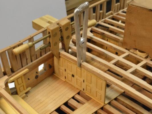
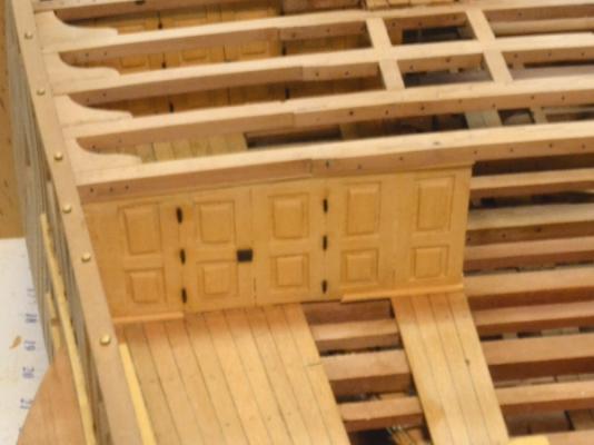
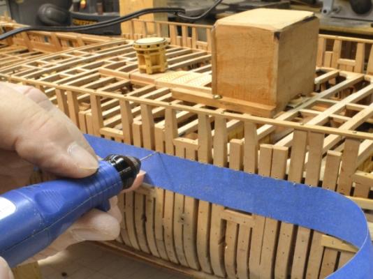
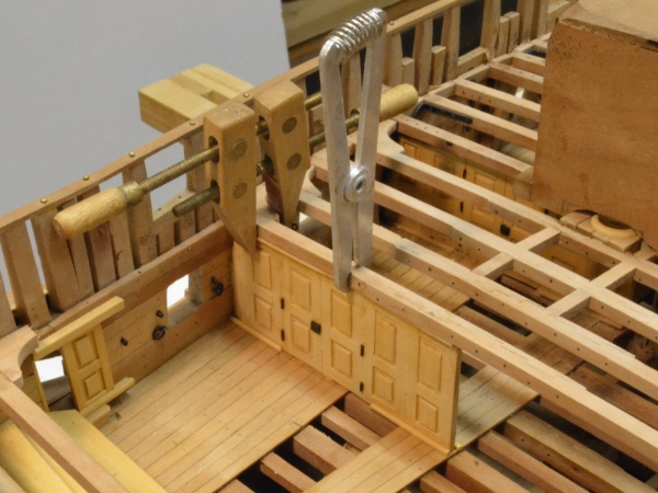
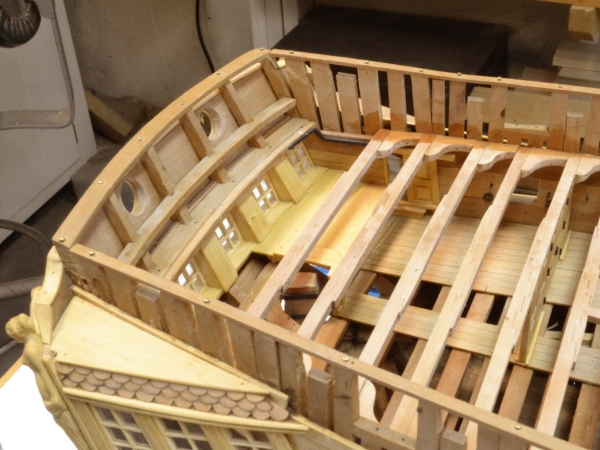
1:60 HMS Naiad 1797 Part 151– Completing the Quarterdeck Beams Posted 9/27/12 Two rainy days have helped move the quarterdeck framing to completion. In the first picture the beam over the partition between the coach and the captain’s day cabin has been installed, the partition is installed and a top retaining cant is being glued into place. Cants at the base on either side of the double doors have been installed. In this picture the upper door hinges have somehow gone astray. They have been restored in the next picture. In the next picture all but the last of the beams have been installed. In this picture the area around the lodging knees is still wet from washing the glue off. In the next picture, the last beam is being sprung to allow it to drop into place. Because of the inward slant of the sides all of the beams needed to be slightly sprung to fit in from the top. The next picture shows the aft end of the model after the quarterdeck beams were all installed. The ugly bunker is still in place and will be for some time. With all the beams installed it was time to complete the bolting for all the deck framing on the exterior of the port side. This side will be left unplanked so the bolts can be installed now. This step will have to await the planking being added on the other side. The blue tape in this picture has been applied on the line of the lodging knees to help keep the line of holes neat. These are all “dummy” bolts. The inside heads were installed in the knees before setting the beams. As I have mentioned before, I gave up trying to drill these all the wat through from the outside and hit the right spot on the knee. In the next picture the quarterdeck lodging knee bolts have all been installed and a bolt for one of the gun port eyebolts is being inserted. The vertical lines of bolts in this picture are those of the iron hanging knees. I have been intent on getting as many of the structural bolts as possible installed. There is no neat pattern to this multitude of fasteners. Once this work is done, this portion of the framing can be given its finish sanding. The work will now move to the waist. Ed