EdT
-
Posts
2,214 -
Joined
-
Last visited
Content Type
Profiles
Forums
Gallery
Events
Everything posted by EdT
-
No, I'm sorry, only English. Ed
-
Glad to see your posting this project, Allan. I'm looking forward to it. Ed
-
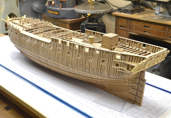
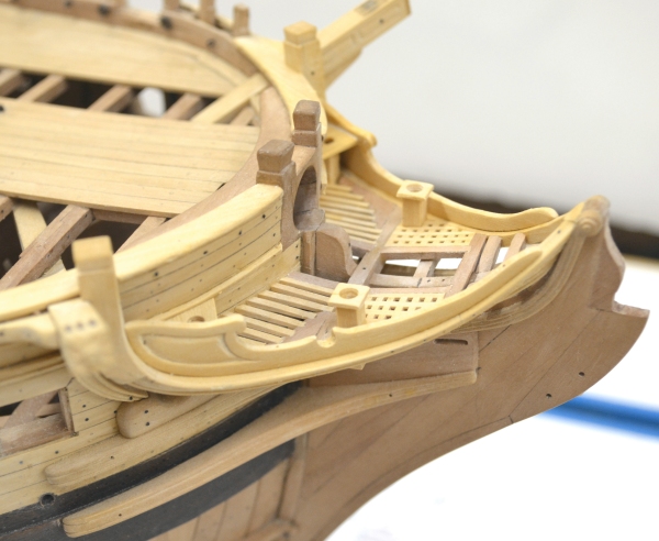
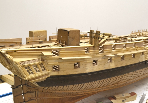
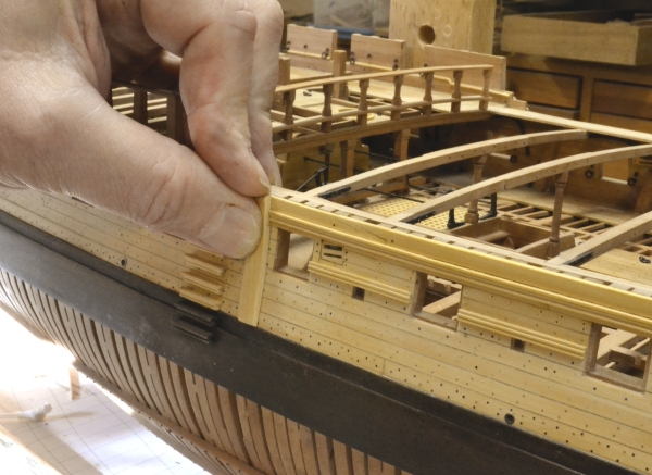
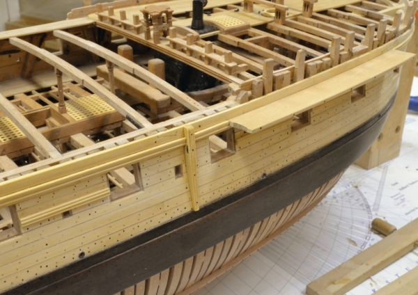
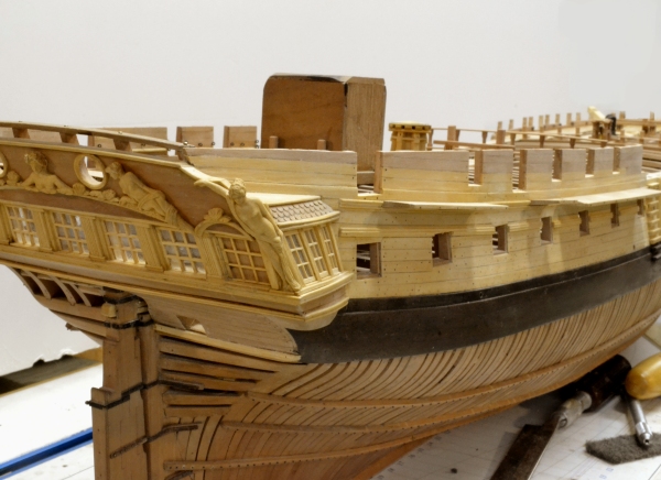
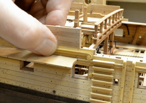
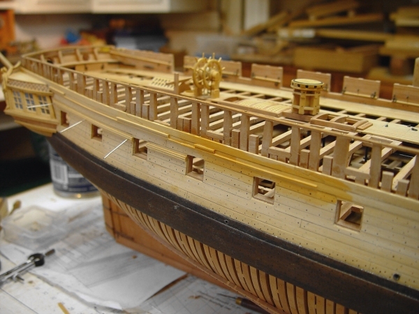
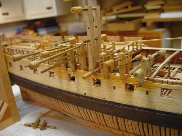
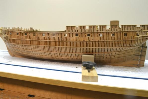
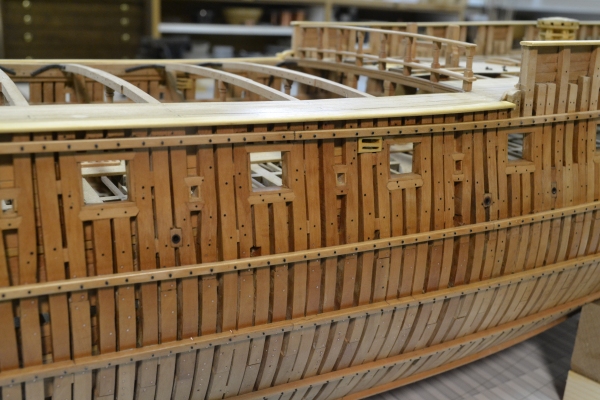
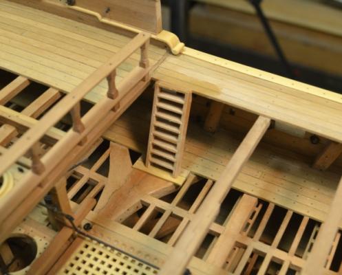
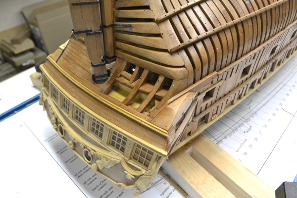
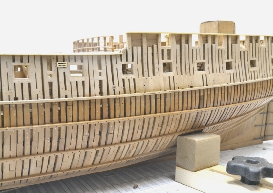
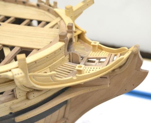
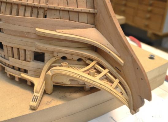
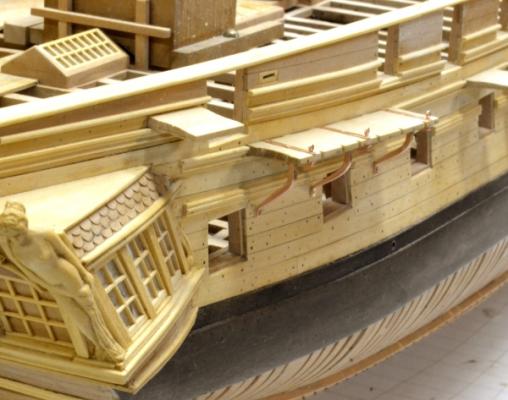
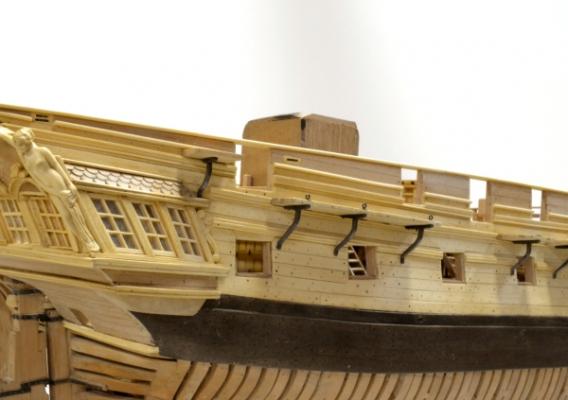
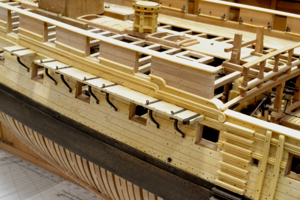
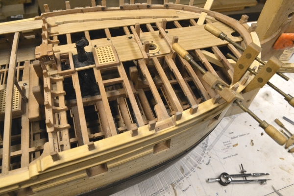
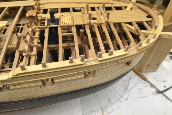
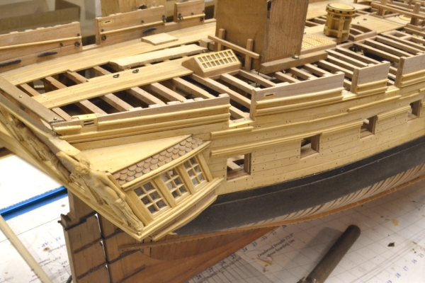
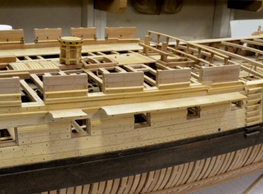
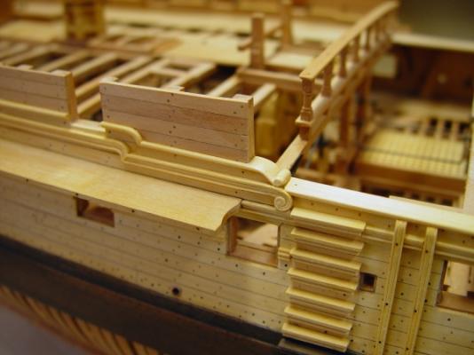
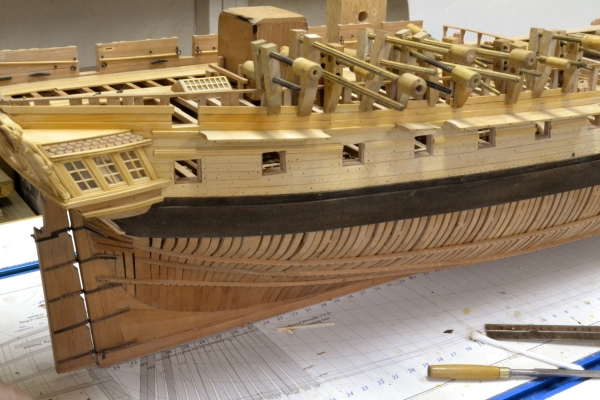
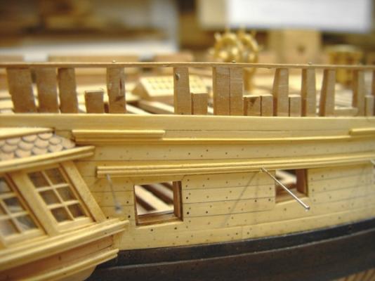
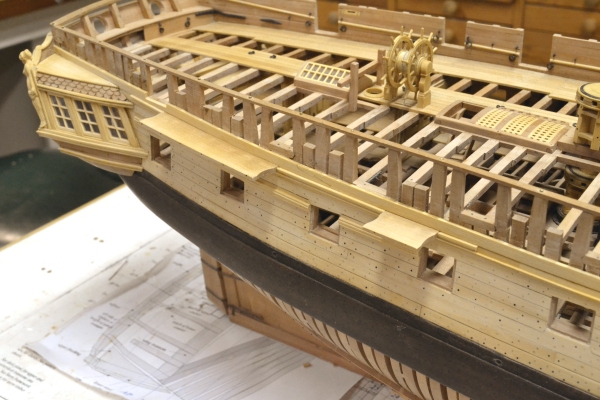
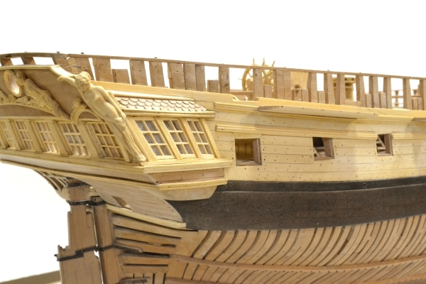
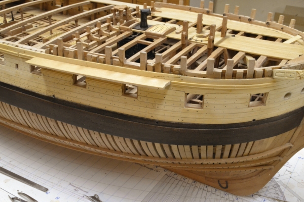
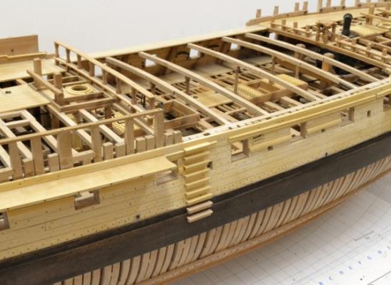
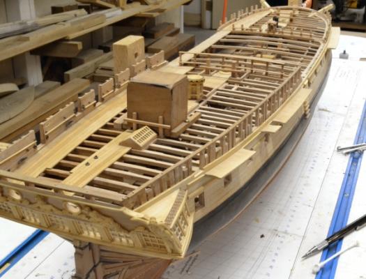
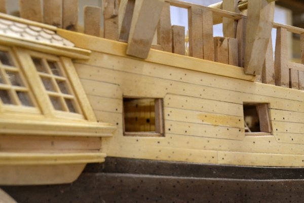
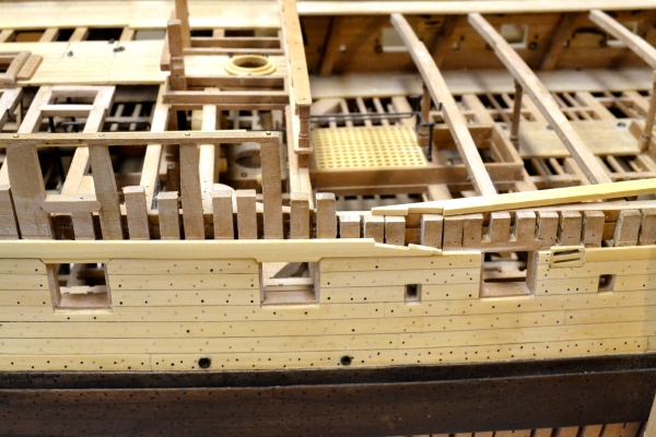
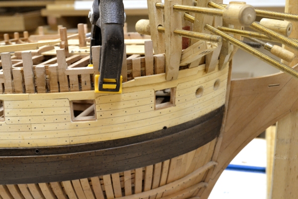
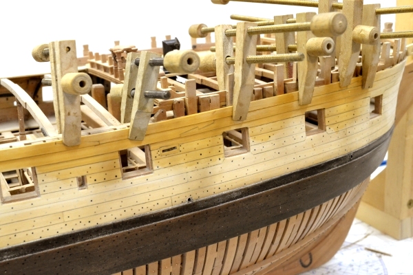
1:60 HMS Naiad 1797 Part 177– Port Side, Lower Stern At the time of the “Great Crash” I was working on the unplanked port side of the model and anticipating completion of the entire model within weeks. It eventually took longer, perhaps without the pressure to keep posting – or perhaps it was resisting crossing the finish line. Anyway, the first picture shows the two additional ribbands installed – one at the height of the wale and the second at the height of the sheer rail. In this picture the planksheer along the waist and the roughtree rail along the topsides of the quarter deck are also in place. The next picture shows a closer view pf the planksheer and the gangways installed along the waist. The tops of these decked walkways is flush with the tops of the planksheers. Part of the final work on the port side was to locate and insert all the missing bolts that were left uninstalled during work on the knees, spirketing, and other internal members that bolt through the hull. The next picture shows a closer view of the port gangway and one of the ladders into the waist. Only the basic structure of the quarter gallery on the port side was installed. This included the stools, the rim with its stanchions and the upper and lower finishings. The next picture was taken after bolting in the lower finishing on the port side with the model inverted. While in this position, the final applications of wax finish were applied to the lower stern and the lower hull framing. The next picture shows work on the lower parts of the starboard quarter gallery that were also installed at this time. In the next picture the model has been righted and all of the lower parts of the quarter gallery are in place. Ed


- 511 replies
-
- 17
-

-
Thank you all for these comments - very much appreciated. Ed
-
ROYAL CAROLINE 1749 by Doris - 1:40 - CARD
EdT replied to DORIS's topic in - Build logs for subjects built 1501 - 1750
Fantastic work, Doris. Absolutely stunning. Ed- 883 replies
-
- 2
-
-
- royal caroline
- ship of the line
- (and 1 more)
-
End of the Reposts! Starting with the next post the material will be new - no more reruns - I hope. Ed
-
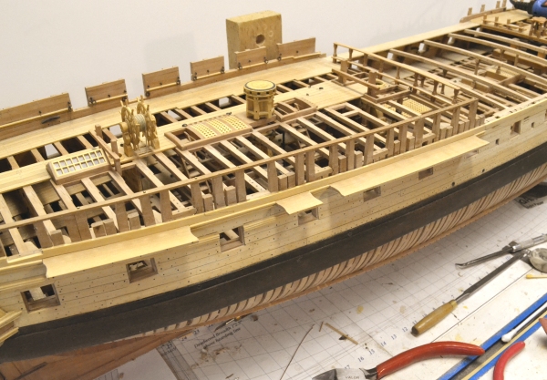
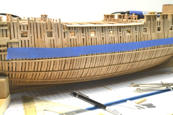
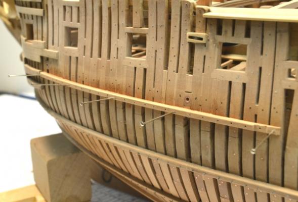
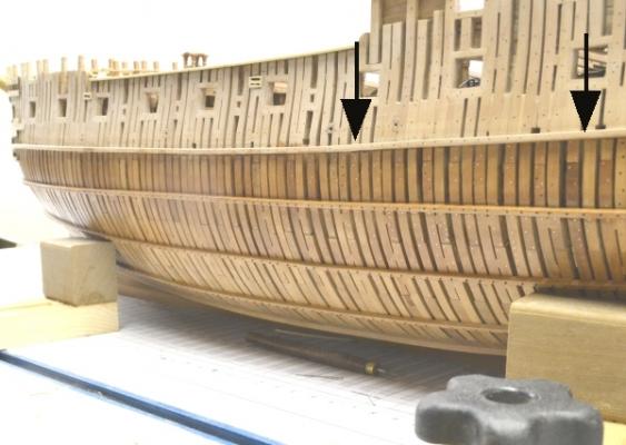
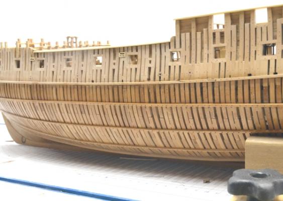
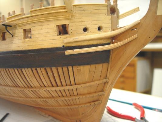
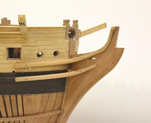
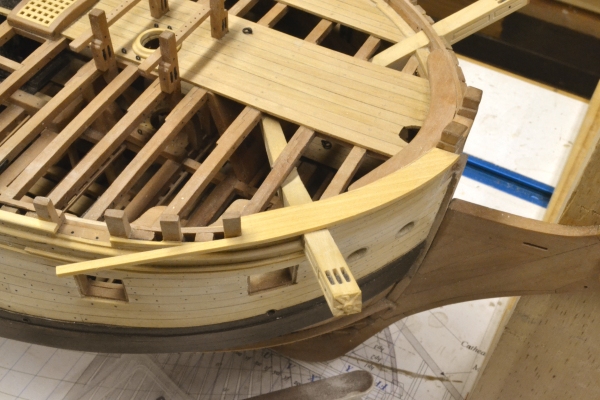
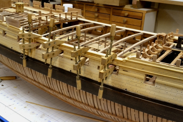
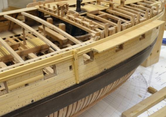
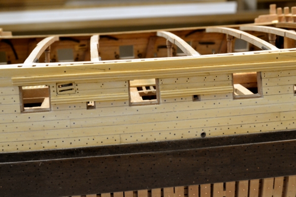
1:60 HMS Naiad 1797 Part 176– Unplanked Port Side Posted 2/4/13 I decided to work next on the unplanked port side of the model. The first picture shows an overall view of this side before starting this work. The framing on this side had been faired and sanded smooth, but there is still quite a bit of detailing to be done to complete this side of the model. The first task was to install fillers between the frames where the chain bolts would have passed through the side. The next picture shows the area of the main chains just aft of the waist. There is not a lot of information about this feature and what I found is buried deep in Steel. These fillers were fir. I installed them between ports where chain plates for all three masts are located and some under the forward part of some ports, since the chains slant aft under these. I made them long enough to handle the chain bolts and preventer bolts at the bottom of the chain plates. The next picture shows some blue masking tape being used to define the line of a ribband to be installed at the line of the top of the wale. The ribbands on the lower hull were done some time ago. There will be two of these on the topside frames. One at the top of the line of the wale and another parallel to that at the location of the sheer rail. The next picture shows the first section being glued into place. The bolt holes were pre-drilled against a fence in the milling machine to keep them on the centerline of the ribband – a 6” x 6” member, joined along its length with hook scarphs. The wet area is from washing off the glue. The next picture shows a somewhat closer view of this looking forward. The horizontal line of bolts above this ribband are holding the knees of the upper deck and the large hole is one of the upper deck scuppers. The chain bolts were set at the height of the lower strake of spirketing (inside). The upper spirketing strake comes up to the port sills. The next picture illustrates the value of taking these pictures – in addition, of course, to being able to post them. The two arrows highlight a length of the ribband that is just slightly out of fairness. I did not actually see this upward bulge by eye. In the next picture the line has been corrected. This section of ribband was pried up, re-glued, and pinned a bit lower, correcting the problem. The area below the ribband is darker because it has been finished. The last picture shows the difference between finished and unfinished pear quite clearly. The wax finish will lighten slightly. This picture also shows the fillings for the main mast chain bolts very clearly. The square openings just above the ribband are the vent scuttle They pass through the top of the upper deck clamp. The toptimbers astride the quarterdeck that go all the way up to the roughtree rail are those that would have supported this rail even without the berthing up. So, the arrangement of timbers is per the original draft, with some left short of the rail as shown on the draft. This picture also shows one of the new adjustable supports for the hull. There are four of these. Ed


-
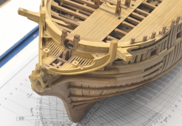
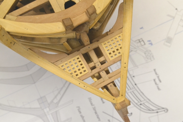
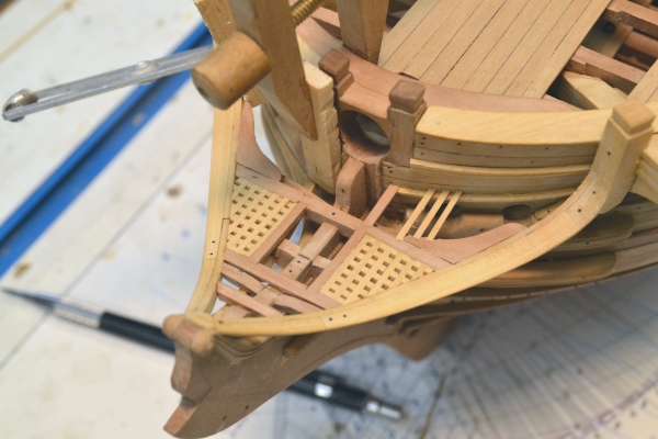
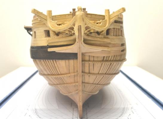
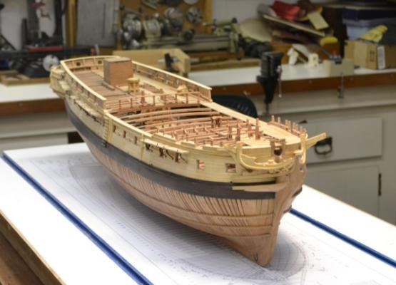
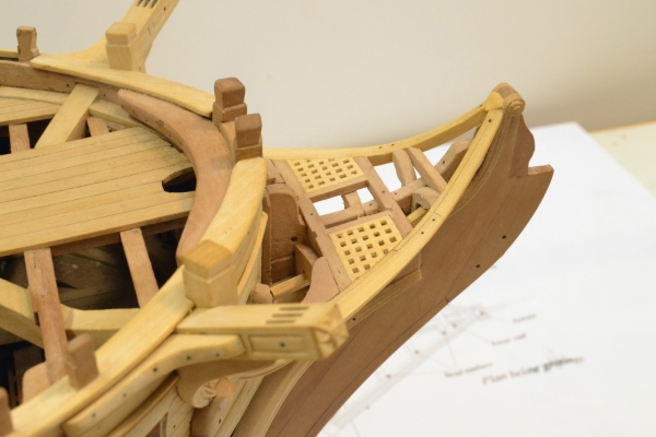
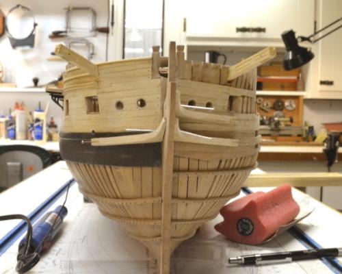
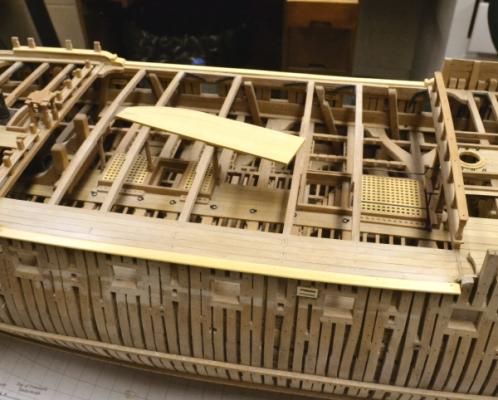
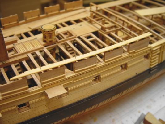
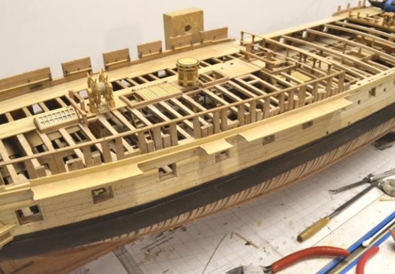
1:60 HMS Naiad 1797 Part 175– Head Continued Posted 1/29/13 In the first picture the rail to support the grating bars on the starboard side is being glued into place with some improvised clamping. The carling and three grating bars are installed on the port side. Since the last post, I had to revise the grating areas. The center cross piece that defines the forward end of these sections was too far aft and would have interfered with the gammoning – a little drafting glitch – now corrected. The next picture shows all the gratings completed and the shafts for the two forward “seats of ease” installed through openings in the grating. The next picture shows the starboard false rail pinned in place. The seats have been added to the tops of the square shafts. The aft seat on the starboard side has been fitted and is just visible above the back of the false rail. The next picture shows both false rails and all the seats installed. The aft seats give some additional support to the fragile tops of the false rails. This can be seen more clearly in the next picture. The figure is still loose in this picture. She makes appearances at various times in these pictures. The next picture shows the hull inverted for work on the head timber facings and the wash cants. In this picture the curved, molded facing pieces have been installed on the head timbers. The wash cants are also installed. I was very happy to have the bunker over the wheel for this upside down work. The next picture shows the current state from dead ahead. These pictures are quite useful for finding little errors of alignment or worse – much better than viewing while bent over at an angle. I was pretty satisfied with the symmetry. The last picture shows the whole model at this stage on a freshly painted shipway - re surfaced with a new copy of the plan. The work on the head is essentially finished at this stage except for a trailboard, some bolting and the small scrolls just behind the feet of the figure. What next? Gun doors? Deadeyes and chains? Finishing the unplanked port side? Haven’t decided yet. Ed


- 511 replies
-
- 11
-
-
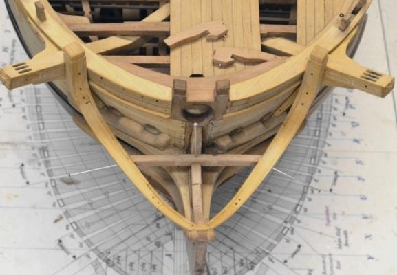
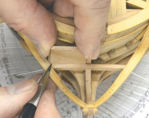
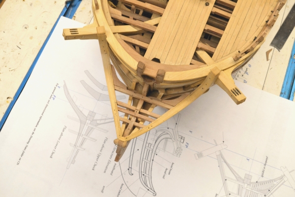
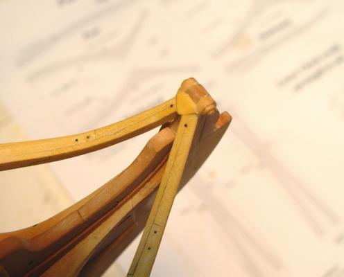
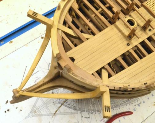
1:60 HMS Naiad 1797 Part 174– Head Continued – Head Framing Posted 1/25/13 Woirk continues on the complex set of timbers that form the structure of the head. With the head rails installed the next step was to fit the head beam. It is shown pinned in place in the first picture. This is a good opportunity to correct any slight misalignment in the head rails by making sure that the score over the gammoning knee is precisely centered on the beam. The beams are rounded up about 2 inches. In this picture, which was taken before the next one, the two aft head timbers have been cut out and are lying on the forecastle. The next picture shows how these timbers were marked out for cutting. At this stage it is very easy to mark the four corners of a head timber on a blank that has been sized to fit the space with its outer edge beveled to match the head rail. The curves of the top and bottom faces can then be marked and the score for the lower rail cut midway vertically between the top and bottom corners of the bottom face. I find this is much simpler and more accurate than cutting these pieces from patterns – and very much easier that lofting accurate patterns as well. In the next picture the starboard aft head timber is being glued in. Mating them against the head beam adds significant strength. In the next picture all six timbers have been installed and also the central crosspiece. The tops of the head timbers need to be lower than the line of the head rail to permit fitting of gratings and also the head beam knees. I elected to pare these back after installation – easier. The next picture shows the assembly from above. The roughed out lower rails are in place in this picture. I find the arrangement with these butting against the bolsters a bit odd, but precisely as shown on the original draft. The next picture was taken after the starboard lower rail was molded and fit into place. The lower curved faces of the head timbers will be covered with molded curved facings. Most of the bolting of the timbers on both sides had been installed when this picture was taken. In the last picture gratings have been installed. Openings for the “seats of ease” will be cut in the outer corners of the grated areas. The openings aft of these grated sections will have fore and aft rails for flooring at the same spacing as the grating slats. The forward cross piece can also be seen in this picture. The last picture is a view from above. [ A lot of finicky tweezer work here. Ed

-
Cabrapente, No, I am sorry. There is only the English version. Ed
-
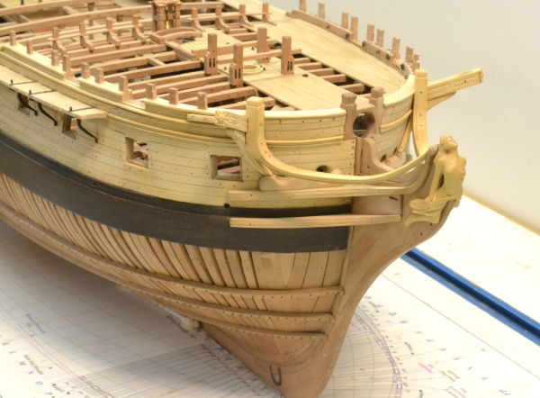
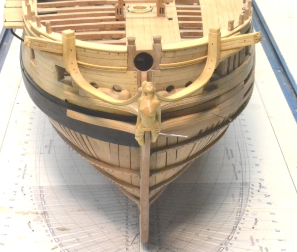
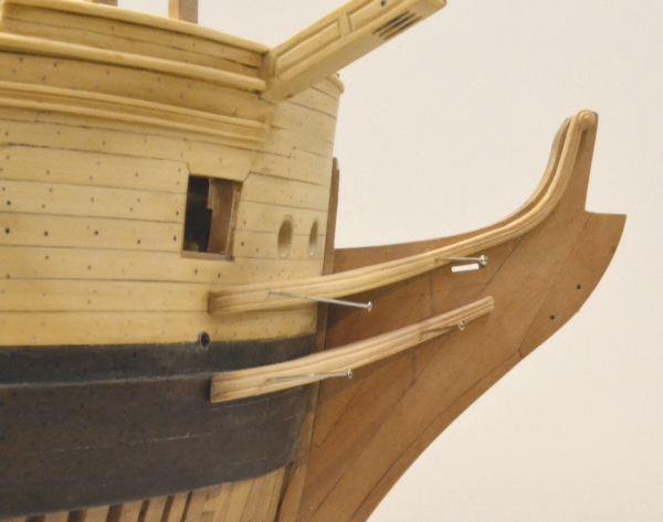
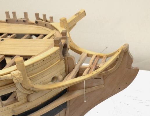
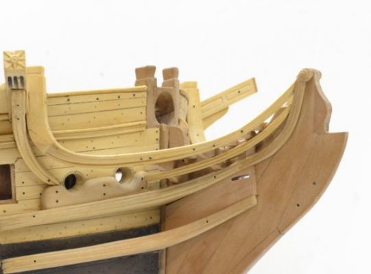
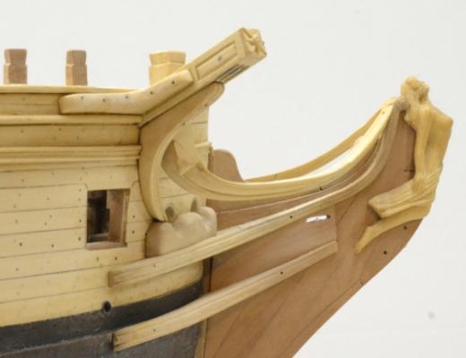
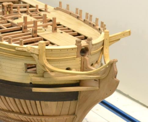
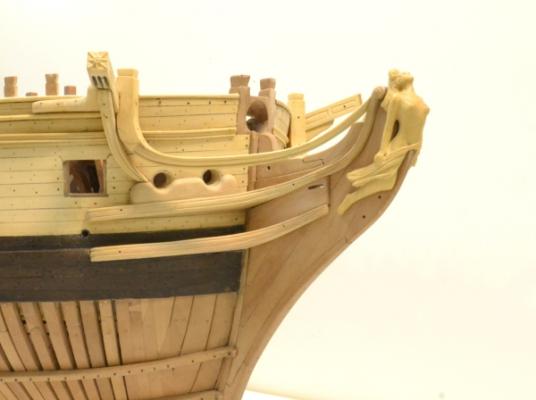
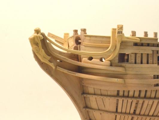
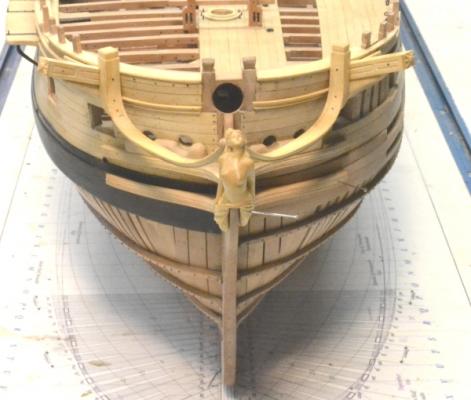
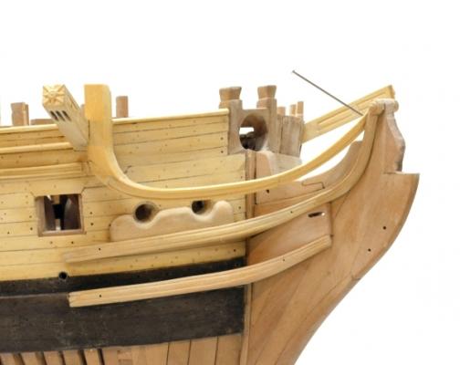
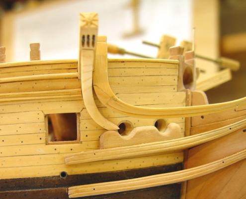
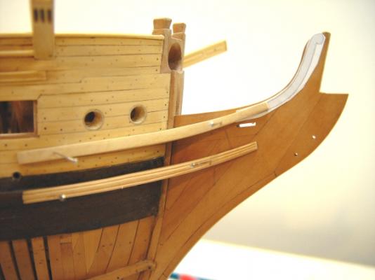
1:60 HMS Naiad 1797 Part 173– Head Continued – Rails and Knees Posted 1/22/13 In the last part I showed the maquette that was used to model the starboard cathead supporter – which I erroneously called the cathead knee. The first picture shows the roughed out final version made based on the maquette – before molding the beads on its outboard face. In this picture the rail and the supporter are still loose. The next picture shows the supporter and the cathead knee installed. ] Both head rails are installed in this picture, but the figure is still loose. The supporter has been molded and installed. The next picture shows the bolster and the bolting of the two head rails to the lacing and hair brackets. Bolts in the head rail joints have also been installed. The next picture shows the current state of the bow. All the parts shown are now glued and bolted into place. The next picture shows more of the bow with the figure positioned. The continuation of the shear rails on both sides have been installed forward of the cathead. The forward bits of the forecastle rails have yet to be installed. The next picture from a lower angle shows the relationship between the curves of the head rail and the upper cheek more clearly. The cathead supporter ends somewhat awkwardly at the bolster. As I mentioned in an earlier post, this is due to the revision in the original draft to add the bridle port and the resulting displacement of the cathead further forward. The next picture shows the opposite side. All the planking necessary to mount the head structure has been installed, bolted and treenailed. The trailboard is not yet installed. The lower cheek is being glued in this picture. As I mentioned earlier, there are still small bits of scroll to be made and fitted to the forward ends of the lower cheeks. The wash cants also need to be made and installed under the lower cheek. The last picture shows the current state from directly forward. The figure is pretty well finished and polished. I still need to touch up the eyes – but just a bit. The next step will be to make and install the six head timbers and the lower rails - another fun job. Ed

- 511 replies
-
- 11
-
-
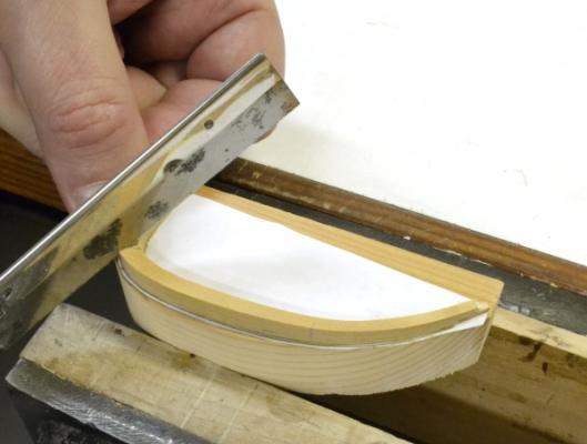
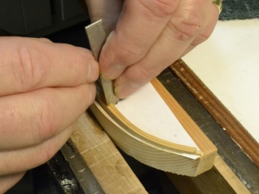
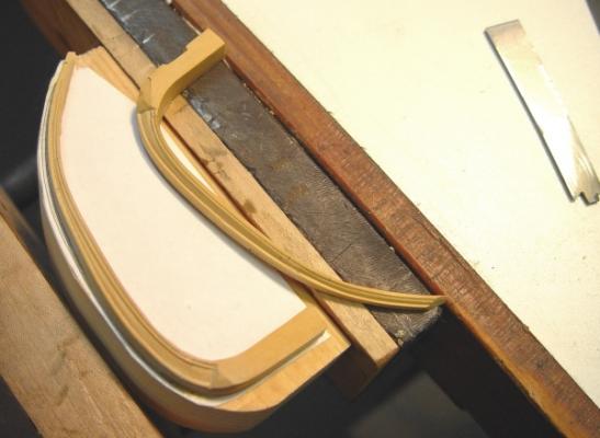
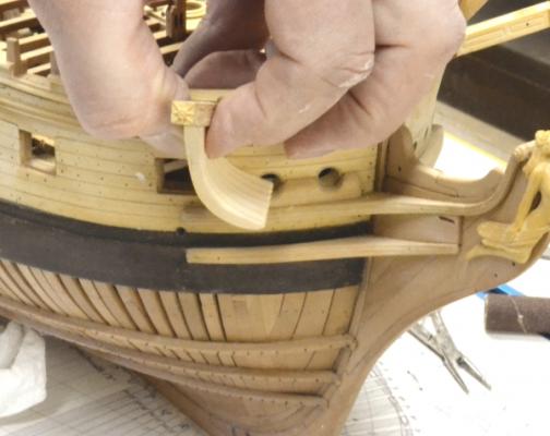
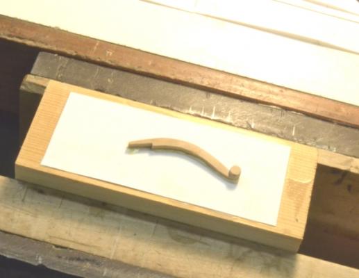
1:60 HMS Naiad 1797 Part 172– Head Continued - Rails Posted 1/18/13 To me, the head rails are high on the list of difficult members to make. With the lofted patterns, cutting and assembling the six pieces that comprise each one is fairly straightforward, as is the tapering of the piece, which narrows at the front. But the fun begins with the next step – shaping the molding - and continues with the fitting of the rails into place. First the molding. The first picture shows the first step – making a saw cut where the vertical corner transitions to a triangular face on the rail. With this cut made the lower outside corner of the rail is then beveled off. The next picture shows the beginning of the scraping of the molding on the upper edge of the rail. The rail was glued to a block with paper in the joint for the forming of the moldings. Because the rail narrows in the vertical as well as the horizontal planes a single scraper cannot do the job. I made two, the two-step pattern shown in the picture for the top edge and a single bead cutter for the bottom edge. Besides the convergence of the top and bottom faces and the curve of the rail, scraping the pattern is further hindered by the two scarphed joints. The cutter has a tendency to grab at the joint and the change of grain direction needs to be watched. Very light cuts and attention to keeping the cutter square to the curved edge is required. This took some time and a fair amount of cleanup of the scraped moldings using small files was also needed. The next picture shows the two finished molded rails. The top rail had already been fit into place as shown in the next picture. A pattern was made first of thin hardwood in the shape of the rail. It was then trimmed back until the forward end fit neatly over the back of the hair bracket. This served as a pattern to cut off the forward end of the rail, which was then trimmed to fit as shown. Before this final trimming the rail was scored on to the cathead. The next picture shows the two fitted rails from above. The next picture shows the first steps toward making the cathead knees. I did not even attempt to loft these pieces with their multiple curves. Instead a maquette was shaped in pine and is shown in one of the many trial fittings in the picture. This will be used as a model for the final boxwood knee. The next picture shows the pine maquette pretty well roughed out and held in place for the photo with a bit of paste.. The shape of this maquette was traced on to the boxwood at each step as it was being formed. The final piece will need to have the lower curve a bit fuller and will need to mate to the bolster a little more to the left, but the pine piece is good enough to use as a pattern for the final one – with slight adjustment. This picture illustrates an oddity in the Naiad design. The addition of the bridle port shown in this picture appears on the draft to have been a last minute design change. This port was probably added as a chase port because in the original design the first of the normal 14 ports was too far aft to use for this purpose. Naiad is the only 38 I have seen with 15 upper deck ports. These forward ports would normally not have guns. Forward guns in early 38’s caused stability problems. Anyway, the last minute alteration disrupted the initially drawn lines of the rails and the curve of the cathead knees because the cathead had to be moved forward. This caused the head rails to have a sharper curve at the cathead and the knee to end rather abruptly on the bolster. This is all shown as a revision on the draft. The picture shows this pretty clearly. Ed
-
Looking good, Gary. I am sure you have seen this, but Steel calls for eye and ringbolts to be made from 1 3/8" rod on the lower deck and 1 1/4" on the upper for 74's. In the absence of better information I would make the hooks the same diameter. Ed
-
1:60 HMS Naiad 1797 Part 171– Head Continued - Figurehead Posted 1/10/13 Based on the comments I guess I glossed over the actual carving of the figurehead so I will offer this still abbreviated description of the process. I hope to document the whole process in much more depth in volume II. Again, I don’t represent this process as ideal, but merely the one I used. I believe I covered the maquette in the previous part. The first picture shows the “composite” side pattern pasted to a block of European Boxwood (buxus sempervirens). This is an outstanding carving wood – hard, dense grain, polishes well. The three patterns used can be seen to the right in the photo. They were created by tracing over the 3D rendered images seen at the left, then overlaid on the drawing of the bow for final sizing, orientation, addition of hair and drapery and any needed adjustments. This was done in the CAD program. These patterns were used for the maquette. The “composite” pattern was made by superimposing the two side patterns to outline the maximum extent of the figure for cutting the overall shape. This was done on the scroll saw. The next picture shows the block having been cut out in both planes. After cutting out the side shape, patterns were pasted on each side and a rough front view sketched in pencil on to the forward side of the block. The side shapes were then roughed out on the scroll saw. These side cutoffs were useful in positioning various features on the carving later. Measurements were also taken from the maquette to locate features. In the next picture the head and upper torso have been given a general shape with the carving clamped in the vise. The head was done first with enough facial detail to assure that the final face could be finished successfully – before moving on to the torso. This preliminary work was largely done with rotary tools and burr cutters or powdered diamond abrasive bits. Getting the face shaped is a critical step and can be difficult. Females – especially attractive young females – are challenging. Overly prominent features, sagging jowls and deep-set eyes all make the figure seems older – and sometimes even masculine. Most of this work was done with hand tools once the basic head was shaped and the eye sockets defined with a small spherical diamond grit rotary tool. The next pictures show the rotary tools used. I have two of these Wecheer tools because I use them so often for drilling and sometimes buffing. They can be held like a pencil. Various bits are shown to the left. The four bits to the left side are diamond abrasive shapes. The tiny burrs in the yellow case are Fox burs. These are very tiny. The rotary tool to the right is fitted with a screw mandrel. A small circle of Scotchbrite pad has been screwed onto the end and is used for buffing. Small sanding boards and flexible sanding strips up to 2000 grit were also used for polishing. The next picture shows the rough carving with the maquette. Some adjustments were made to the final head shape and pose. The upper torso is pretty well shaped in this picture. The next picture shows some of the hand tools used for carving and final detailing. A surprising amount of rough paring could be done with a simple modeling knife but straight chisels were used quite a bit for that as well. The tools to the left are small gouges made from drill rod. The very tiny gouge at the far left was made from a bit of syringe tubing. The small abrasive files were very useful for shaping and veining. They can be used in any direction and are good for smoothing out gouge cuts. The Two Cherries tool is a very mall curved gouge. I also used a similar v-gouge quite a bit. In the next picture the roughed out figure has been fitted to the bow. The mounting slot was cut with a saw and square files. A major portion of carving block behind the figure remains. This allows it to be clamped in the vise. Once the figure was fit into place this could be removed as shown in the next picture. The figure is almost complete in this picture. There is still some final work to do on the hands, feet, face, etc. Closeup photos like this one – or closer - are very helpful in finding areas for further work. There will be a short extension of the lower cheek with a scroll installed on each side just behind the figure’s foot. The last picture shows the figure at this stage from the other side. Because the figure represents a swimming nymph, there is not a lot of drapery; so the area behind the torso had to be filled in. I did this by extending slightly the upper part of the lacing timber. This is visible in both these last pictures. Doing this in pear helped define the slender shape of the figure. Ed


-
1:60 HMS Naiad 1797 Part 170– Head Continued Posted 1/4/13 Things slowed down a bit over the holidays, but I was able to continue work on the head structure. In the first picture the assembled upper cheek on the port side is being attached. The two parts of these assemblies were glued together first while clamped in place, but not glued to the beakhead. The assemblies were then aligned to the back of the lacing and glued on one at a time. Since there was wait time being gluing these parts together I started work on the figurehead. The next picture shows the beginning of work on a maquette made with an epoxy molding compound – MagicSculpt. I have used this material extensively for making patterns for casting of 1:60 military figures. It is applied over a copper wire armature pushed into a cork to enable handling. The material is then built up progressively and shaped using fancy tools like round toothpicks. The design of the figure took some research and some drafting time. It is supposed to represent a water nymph (a naiad) swimming. As I have mentioned earlier, there is no decoration plan for Naiad, so the carvings are all speculative. To complicate the decoration decisions, Naiad was under construction when the Admiralty issued its 1796 order to reduce decoration and eliminate full figures. This second part was very unpopular and may have been ignored at least for a time. I feel reasonably safe with the level of decoration on the Naiad model – no one can know for sure. The next picture shows the almost-completed model posing near the head. In this picture a template scrap is being used to position the figure. The next picture shows the finished maquette mounted on the head. In the picture the bolster is also being glued in place under the hawse holes. The gammoning knee assembly has also been made with a scarph joint joining its two parts. It is glued in between the gammoning piece of the head and the stem. The next picture shows the structure as the trailboard was being fit between the two cheeks. After it was installed, holes were drilled from the opposite side at the ends of the gammoning slot. This opening was then filed out as will be seen in some of the later photos. The opposite side can then be done in the same way. In the next picture, the carving of the final figurehead is well along. There were a lot of steps to get to this point that I will not take space here to describe. The three views on the pattern sheet and the maquette were of course used as a guide and to transfer measurements as the carving progressed. The next picture shows the unfinished figure being fit to the structure. The figure is not yet finished except for the shaping of the torso and the face. The face was done first to save work in case it didn’t turn out. Fortunately only one try was needed, so I have spared myself the agony of wasting a good sized block of Euro Boxwood – so far. A slot in the figure to fit on the structure was cut with files and a small chisel after being roughed out on the scroll saw. The next picture shows the figure fit temporarily into place. With the width of the slot determined, the lower legs can be finished. The arms, hands, hair and drapery still need to be carved as well. This can now be done with the position of the figure and its intersection with the underlying structure established. Although carving is a nice diversion, there is still a lot of interesting work to do on the head structure and that is still the priority right now. Ed


-
Grant, here is a link to what I am using. http://www.contenti.com/products/soldering/420-860.html So far, I have been quite satisfied with this. Ed
-
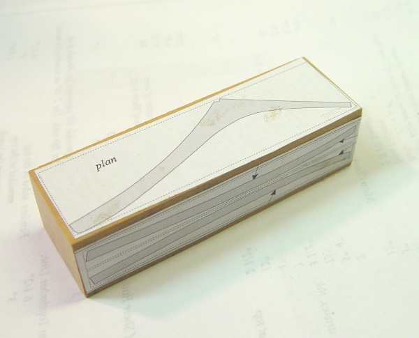
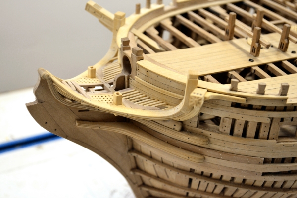
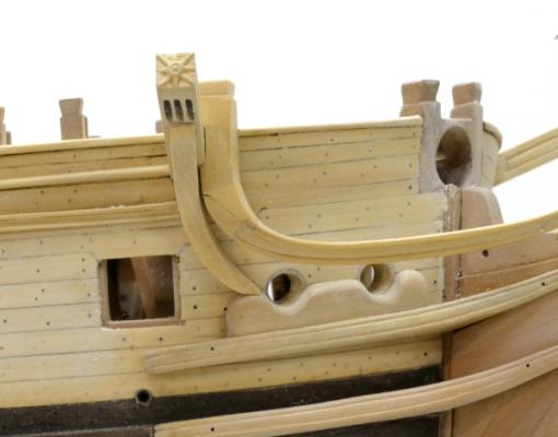
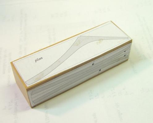
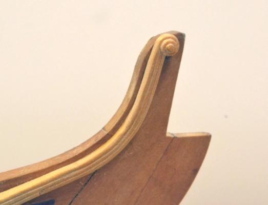
1:60 HMS Naiad 1797 Part 169– Cheeks Posted 12/2312 Lofting the patterns for the cheeks was almost as interesting as making them – perhaps more so. In addition to getting a close approximation of the shape, I also wanted to minimize the waste of the precious European Boxwood. The patterns were lofted as a projection on the surfaces of a block of wood oriented for good grain direction and from which two of these could be cut. The patterns pasted on to a block of wood are shown below. The patterns are placed back to back on a block wide enough to allow the sectional views to be cut first – on a scroll saw. The upper part with the “plan” view was then taped back on to the convex side of the shape cut out. The plan shape was then cut out. There is a similar plan pattern on the opposite side. To be sure of a fit, I tried this out on a pine block first. The next picture shows the upper and lower starboard cheeks pinned in place during fit up. These two cheeks are so similar I was able to use one set of patterns for all four. The lower cheek in this picture has had its molding scraped on. The next picture is a view from the front while these were being fit up. The next picture shows the pattern for the hair bracket pasted on to check for a fit and mark the ends of the scarph joint. The patterns for the hair brackets were simple since they are parallel to the centerline. I cut the lower cheek just a bit short - maybe two inches. I may replace this to allow the trail board to extend further beyond the end of the gammoning slot. This was a cutting - not a drafting – error. The next picture shows the port hair bracket glued to a block for carving. The scarph was cut and fit first, using the pattern as shown in the previous picture. The next picture shows the finished scroll on the starboard side. This has been glued to the cheek but not to the beakhead. The scarph is just visible at the left. The moldings were cut with a bead scraper one edge at a time. This allows the beads to close gradually towrd the front as the siding of the member gets smaller. The last two pictures picture show the assembly pinned in place. At some point between the early 1780’s the hawse holes moved from between the cheeks to above the upper cheek. I had not noticed this before, but came across this difference when checking some model photos – Minerva and Leda in the Rogers collection for example. I find this very interesting and will do some research to see when this switch occurred and the relationship between the holes and the upper deck in the two variations.. This may be the last update of the year, so I will wish everyone a very merry Christmas and a happy 2013. Ed

-
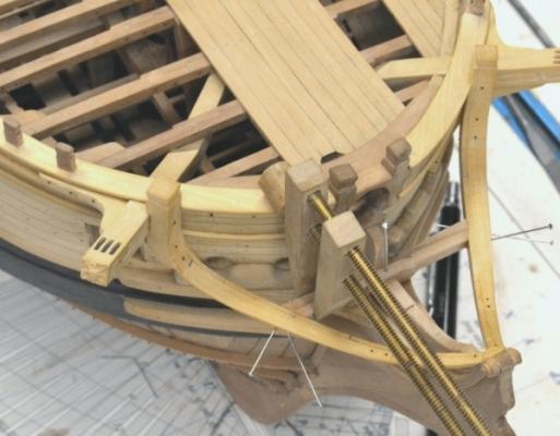
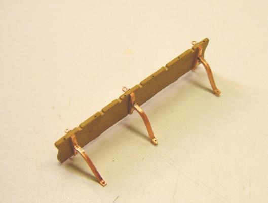
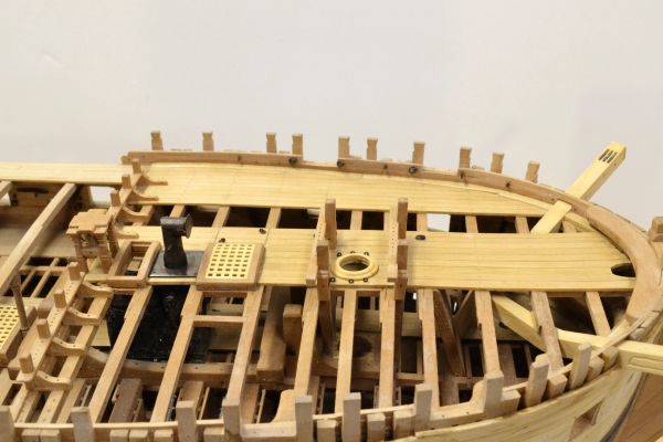
1:60 HMS Naiad 1797 Part 168– Channels Posted 12/12/12 The next leap forward was the installation of the channels – but first a small carving chore – the scroll just forward of the gallery windows. The next picture shows the mizzen channel with its supporting iron T-plates installed. The T-plates were fabricated from two pieces of copper. A slot was milled on the bottom of the horizontal piece to fit the end of the lower arm. The slot was milled before ripping off the individual pieces on the circular saw. These were then silver soldered. As the next picture shows there are backing plates for these brackets on the tops of the channels. Also, the outer bolts are eyebolts. The slots for the deadeye bindings were cut before installing the T-plates. The T-plates were attached with copper through bolts, peened to hold everything in place. The next picture shows the main channel. The tops of the eyebolts were clamped in a vise to allow the bottoms to be peened over. The T-plates ate generally located so they can be bolted into the second frame from the gun port. I say generally because these also need to avoid the slots for the deadeye bindings that were located from the original sheer plan. They also need to avoid the long horizontal bolts through the channels. Neither of these channels are permanently installed yet. Note the bracket for the main stunsail boom at the forward end of the main channel. The next picture shows the aft channels and stools installed. The ironwork was blackened first. The channels were then washed clean, dried then glued to the side, aligned and secured with bolts at the bottom ends of the T-plate arms. They are very secure. The next picture shows the main channel. The copper was blackened as usual with liver of sulfur after the parts were attached. To solder these parts I used a new product – a silver solder paste with copper in the composition. It fluxes around 1250 degrees like other silver solder, but unlike ordinary silver solder it can be blackened with LOS. There is not much solder showing on these parts but I did some tests before making these to be sure it would blacken. The next picture is a closer view. The bolts at the ends of the lower arms were installed like those on the iron knees on the deck beams. A under-sized hole drilled into the frame under the planking, a sharpened bit of copper wire forced in then clipped off just above the surface of the arm, then peened over by hammering – following by a touch of LOS on the bolt heads. The last picture shows the fore channel from above. Ed


- 511 replies
-
- 11
-
-
Thanks yet again, everyone. Just a dozen or so reposts to do to get us back to where we were in February. Ed
-
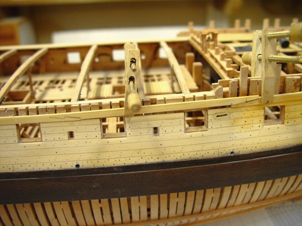
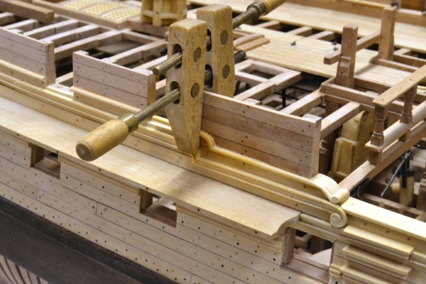
1:60 HMS Naiad 1797 Part 167– Topside Rails Posted 12/09/12 The first picture shows the roughed out forward forecastle rail being fitted. Once it was fit between the knighthead and the first timberhead, the outer curve was shaped, the width marked along the inside and the forward curved section cut parallel to final width. Both edges were then molded with the half-round scraper. The aft end was then boiled and curved to fit the frames. In the next picture this rail is almost complete. The center pieces and the inside rails have been fitted to the completed outside rail. The next picture shows the final rail installation completed. Before installing the roughtree rail on the quarterdeck, the two fixed blocks and the last parts of the drift rails needed to be installed. The next picture shows that work completed. Work also began on the other side. The next picture shows the planksheer at the waist on the port side installed. The piece of boxwood on the waist beams will be used for the port side forward forecastle rail. In the next picture the first section of the starboard roughtree rail is being installed. First it was formed with the half-rounds on each side. The width of this rail is just under 16 inches. The tops of the frames are just under six inches, the top planking inside and out is 2 ½ inches and the 2 ½ inches of half-round extends outside of the planking on each side. If my math is right that is just less the 16 inches. The forecastle rail width was set in the same way but is slightly wider because the spirketing on the forecastle is thicker. The inside of the frames were given a light sanding to bring them to the correct thickness. The rail was pinned to the correct curve and projection on the planked side. In the picture it has been raised up on the pins to allow glue to be applied. I joined the fore and aft sections of this rail with a hook scarph. In the next picture the aft section of rail is being glued down. The two clamps are making the hook scarph joints tight. The next picture shows the forward section of rail on the opposite side glued down. Ed
-
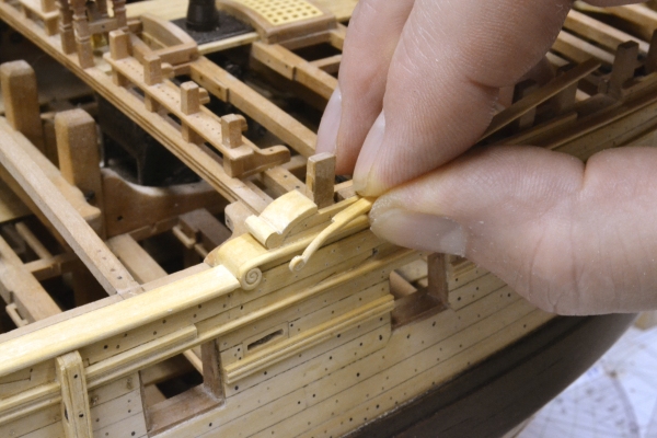
1:60 HMS Naiad 1797 Part 166– Side Planking, Rails and Details continued Posted 12/06/12 After the last post, there was some discussion of the channels and how they were fastened to the side planking. The first picture shows the mizzen channel still only pinned in place, but the drainage openings at the side have been cut and the lines of the planks that make up the channel assembly have been scribed. I decided to save some time and make the channels in one piece rather than faying curved planks together.. The next picture shows the way the ends of the drift rails were made. The oddly shaped piece set on top of the drift is oversized relative to the srolled end of the rail that will be glued to its face. When attached the shaped block will be pared and filed off to match the scroll. This was also the method used on the two ends of the drifts on the forecastle. With these pieces in place, the planksheer could be installed and this is shown in the next picture. It is pinned for alignment then glued and clamped down using the port openings for clamping. The next picture shows the upper drift rail of the quarterdeck after installation. This was installed as one long piece to assist alignment. The port openings were then sawed out. The forward scroll of this rail has been installed. The small piece of curved rail just aft of that piece has yet to be installed. The next picture shows this being glued in place. In the next picture the scrolled outer rail section is being matched up to the aft end of the upper forecastle drift. This rail will be formed in pieces around the timberheads, which will be shaped into the tops of the forward frames. The curvature of this rail, the scrolled end and the number of openings for the frames make this a difficult job to do in one piece. The next picture shows the installation of this rail in progress. The scrolled ends have been pretty well finished off along with the first piece beteen the aft timberheads. The next piece has been glued in but not leveled yet. The outer part of this rail with the scroll was made in one piece forward to the first port opening. The inner part of the rail will be installed last. The last picture shows the scrolled end of the drift rails to the quarterdeck. The area above the upper drift rail would have been left as an open rail in earlier days. The berthing up above this line that I have installed is planked from darker pear to highlight this. The difference in color should be more pronounced after finish is applied. Almost ready for the roughtree rail. Ed

-
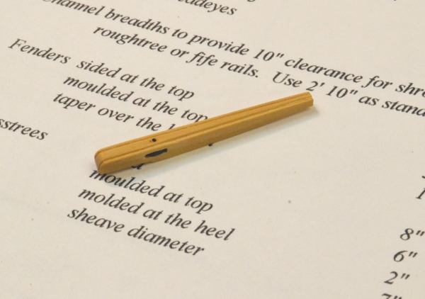
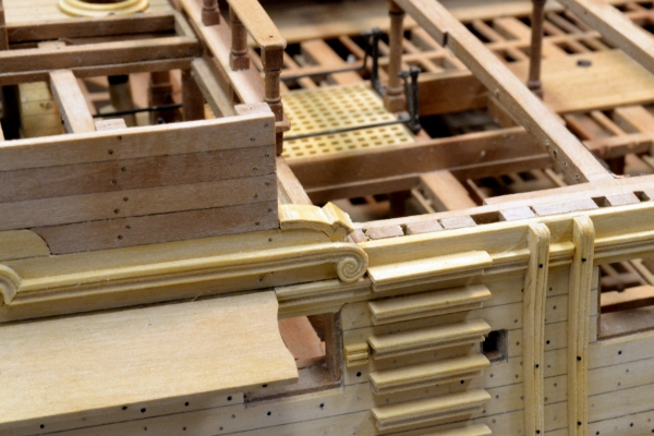
1:60 HMS Naiad 1797 Part 165– Side Planking, Rails and Details Posted 11/28/12 Work continues at a pretty good pace. The first picture shows a blank for the two fenders being checked for shape against the side. The inside face was shaped on a larger block. A parallel line to that shape was then drawn on the piece and the blank shown above was cut off on a scroll saw. The two fenders were then ripped off from this and tapered to the bottom. The beaded moldings on the outside edges were then formed with a scraper. The next picture shows the fenders installed. The next picture shows the chesstree – shaped by the same process. The sheave opening was made by drilling a line of small holes then cutting out the rest with a very small mortise chisel. The next picture shows the installed Chesstree. The planking above the shear strakes at the side of the quarterdeck is shown in progress in the next picture. The next picture shows the planking and “berthing up” of the quarterdeck area completed. I used European boxwood for the area below the top drift rail. This would have been planked even if the full berthing-up was not installed – as on earlier ships. The area above that line was planked with pear. The next picture shows the forward scroll on the lower drift rail being fitted before gluing. I am using the same profile for this rail as for the shear rail below. This piece was tricky to fit because it sits over the break in planking thickness between the 3” shear rail and the 2 ½” strake above. That doesn’t seem like much difference but some paring was needed to get it to lie flat. Carving the scroll took a couple of hours using small gouges, a scribing tools, a very small burr and a 10x Optivisor. My hands are getting too shaky for this. There will be a small simpler scroll atop this piece. The forward part of side plank and the frames above will be cut back to match it. Ed


-
1:60 HMS Naiad 1797 Part 164– Rails and Channels Posted 11/24/12 With the shear strakes installed, the next step was to install the shear rail and the waist rail below it. The top of the shear rail follows the line of the top edge of the lower shear strake and the top of the waist rail is 2 feet below it. The shape of the rails was scraped on the edge of a 6” thick plank using a scraper filed out on a piece of plate. There are two different shapes for these. After scraping the rails were ripped off to the 3” thickness. All of the planking and the trim in this picture is European Boxwood. The shear rail was cut out to seat the channels – the mizzen channel in this picture. These are about an inch thinner than the shear rail. The next picture shows this work progressing forward. Again, the wet spots are from washing off the glue. The next picture shows the first channel sections pinned in place. I decided to make these of Castello – like the decks. They are tapered to the outer edge. Bolt heads are just visible. They are held in place at this stage by short copper stub “bolts”. I intend to install the iron T-plates and other detail before installing these permanently. The next picture shows another view of this. In the next picture the main channel is fit into place. I made all the channels 2’10” in breadth. The contract calls for these to be broad enough to allow the shrouds to clear the roughtree rail with 10” clear. This took a bit of layout work. The slots for the deadeye bindings will be cut before installation of the ironwork. In the next picture the rails have been extended forward into the waist area. The waist rail in this area will have to be cut out where it crosses over the sweep ports. The end of the shear rail at the left of this picture will butt right up against the forward fender. The planksheer will fit directly on top of the upper shear stake in this picture. That line also defines the tops of the frames. The planksheer was flush with the gangway planking in this area. The next picture shows the fore channel and the shear rail up to the cathead. The fore channel has more curve than the other two – as does the rail. The forward end of the rail will be trimmed back when the cathead knee is installed and the rail forward of that will be installed then as well. In the next picture the side steps have been installed. The break in the shear rail just forward of the steps is left for the fenders. The bottom two steps are pear and will be stained to match the wale. The molded shape of the steps was formed with a third cutter and the steps filed to that shape at the ends. The next picture shows all the channels installed along the side. The bunker has been put back over the wheel. I had left it off after finishing the quarterdeck to prove to the Thanksgiving guests that it actually turns the rudder. Now it is quite safe. Ed

- 511 replies
-
- 10
-
-
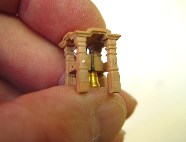
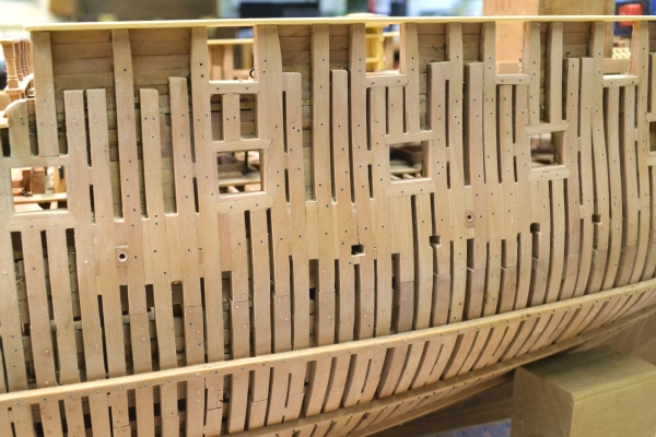
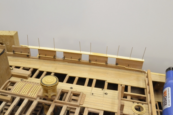
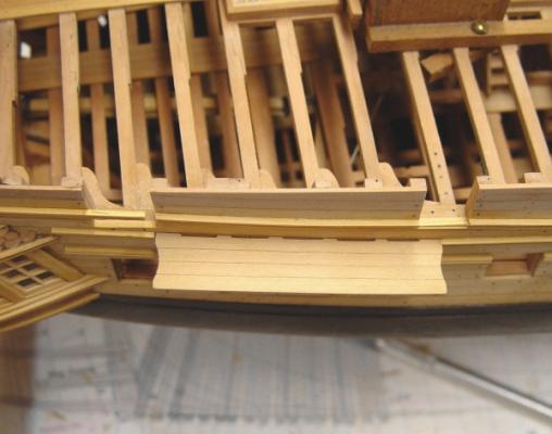
1:60 HMS Naiad 1797 Part 163– Sheer Strakes Posted 6/16/13 Before moving to the outside of the hull there are two pictures relating to the work in the last post. The first is a close-up of the belfry taken during its final polishing and before bolt head blackening. The next is a picture of the finished forecastle. In this picture the crosspieces to the bits have been installed as well as the ironwork on the side for the guns. Also the stack and base plate have been re-blackened again for the fifth time. I am hoping they will hold this finish. This time I used another “blue” product – Brass Black – for gun metalwork and followed their instructions exactly. We’ll see what happens. So, on to the outside of the hull. The first picture shows the beginning of the installation of the sheer strakes. These are two strakes, each about 10” wide and 4” thick, about ½” thicker than the planking just below. The top of the lower strake will be the top of the shear rail – and also the top of the channels – so the line needs to be correct. New measurements were taken all along the hull to recheck this and some minor adjustments to the plank below were made. The next picture shows the lower strake installed up to the waist. The two strakes also need to come up flush with the tops of the frames in the waist area. This picture also shows the hooked scarph for the next section which is resting on the side just above. This picture also shows that as the lower strake begins to rise relative to the ports, it has been widened to fit down to the port lintels to avoid a too thin bit of lower plank on these two ports. Aft of this it rises enough to allow the lower plank to be cut out leaving half or more of its width. The area of the sheer strake plank on the after port has been pared back in thickness to match the planking below. The other has yet to be cut in this way. The next picture shows the work beginning in the bow. This piece was boiled first then clamped around the curve to dry. The joints were then cut and in this picture it is being glued in place. The thickness of the plank being installed was thinned down at the front to fit the rabbet in the post – as was done for the wales planks. In the next picture a closing piece of the lower strake is being fit up and its joint marked. The next picture shows a section of the upper strake being installed. The last picture shows the closing piece of the upper strake being installed. The dark areas in all these pictures are moisture from washing off the glue. Once these two strakes are leveled off and fine sanded, the shear rail can be installed, followed by the waist rail two feet below it. The sizes and spacing of all the rails varies between the sources – Steel, contracts and the Naiad draft. In general I followed the draft where a good measurement could be taken. More on that in the next part. Ed


-
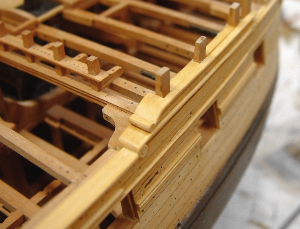
The standards installed on the syanchions of the forecastle breast rail in the above post are not correct and were removed later to cut two sheaves into the lower part of each stanchion. Ed