


Pete Jaquith
-
Posts
338 -
Joined
-
Last visited
Reputation Activity
-

 Pete Jaquith got a reaction from Bill Morrison in Red Jacket by MrBlueJacket - FINISHED - BlueJacket Shipcrafters - Scale 1/8" = 1' (1:96)
Personally, I prefer plank on solid (POS) to plank on frame (POF) construction. I have used both machine carved kit hulls and laminated scratch built hulls. The following notes apply:
Machine Carved Hulls
Requires care in establishing reference lines May require hull, deck, and/or bulwark build up Hull carved inverted using reference board and templates Hull initially carved to outer plank lines Upper hull recessed for 3/64" planking, lower hull coppered Thinning carved bulwarks requires care, they may be replaced with built up bulwarks Reference my Brigantine Newsboy build log on MSW Laminated Scratch Built Hulls
Ease in establishing/maintaining reference lines Maintain rectangular configuration until completion of deck carving, deck layout, and drilling of mast holes Hull carved inverted using reference board and templates Hull initially carved to outer hull lines Upper hull recessed for 3/64" planking, lower hull coppered Requires built up bulwarks with timberheads slotted into hull block Reference my Topsail Schooner Eagle build log on MSW I find both techniques work well and require ~ 60 hours for hull carving
Regards,
Pete
-
 Pete Jaquith got a reaction from Ingo in Type of wood for filler blocks?
Matt,
I have had good experience with filler blocks, both to assist in hull fairing and to support planking. I recommend something firmer than balsa such as bass, pine, or popular. I have attached pictures of my Fair American build for reference.
Regards,
Pete
-
 Pete Jaquith got a reaction from KeithAug in Arethusa by Elia - 1907 Knockabout Banks Fishing Schooner
Elia,
Nice looking spars and rigging ironwork. I look forward to seeing your work on silkspan sails as I plan to go that way for future builds.
Regards,
Pete
-
.thumb.jpeg.fc5d633a7b34428fcf19419a73d56d55.jpeg) Pete Jaquith got a reaction from EricWilliamMarshall in Eagle 1847 by Pete Jaquith - FINISHED - Topsail Schooner
Pete Jaquith got a reaction from EricWilliamMarshall in Eagle 1847 by Pete Jaquith - FINISHED - Topsail Schooner
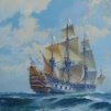
The Topsail Schooner “Eagle” had a length of 81’ 7”, beam of 22’ 8”, depth of 7’ 10”, and tonnage of 140 tons. Both the “Eagle” and her sistership “Arrowsic” were built in Arrowsic Island on the Kennebec River (near the present shipbuilding city of Bath, ME) in 1847 for the lumber and ice trade by builder Samuel Pattee. During the mid-19th century small schooners of this sort were widely employed in the East Coast trade; their schooner rigs an easy adaption to the prevailing westerly winds and economy in crew size.
The model was scratch built to a scale of 3/16” to the foot (1:64) using old Model Shipways plans by William Zakambell. Additional research was conducted at the Maine Maritime Museum in Bath, ME where a large scale model of the “Arrowsic” is on display. The model is plank on solid construction, with built up bulwarks, planked decks and topsides, coppered bottom, and scratch built deck furniture/fittings. Limited commercial fittings were utilized where appropriate, and the rigging is proportional linen line with Warner Woods’ blocks. The Topsail Schooner “Eagle” is my 3rd wooden ship model and my 1st scratch build.
Pete Jaquith
Shipbuilder
-
Pete Jaquith got a reaction from EricWilliamMarshall in Eagle 1847 by Pete Jaquith - FINISHED - Topsail Schooner
Welcome to the Topsail Schooner "Eagle" 1847 build log,
Finishing up the running rigging and final pick up, key points include:
>>> Final drops of thinned white glue to secure rigging lines
>>> Rigging coils installed
>>> Ship's boat secured
>>> Final paint touchup
>>> Model cased and mounted in brass pedestals
The model now rests in the home of a dear friends in the State of Maine. They are Maine natives, which is appropriate for this ship is typical of Maine coastal traders of the mid 1800's.
Pete Jaquith
Shipbuilder
-
Pete Jaquith got a reaction from EricWilliamMarshall in Eagle 1847 by Pete Jaquith - FINISHED - Topsail Schooner
Welcome to the Topsail Schooner "Eagle" 1847 build log,
Moving ahead with the spars, sails, and running rigging, key points include:
Sail & spar installation sequence:
>>> Jibs and fore staysail (with fore stays)
>>> Main sail, main gaff topsail, 34 star ensign
>>> Fore sail
>>> Fore top sail and Eagle pendant
Rigging setup:
>>> Standing rigging (fore stays, main stays, shrouds, backstays, and ratlines)
>>> Jobs and fore staysail
>>> Main sail, main gaff topsail, 34 star ensign
>>> Fore sail, fore topsail, and Eagle pendent
Pete Jaquith
Shipbuilder
-
 Pete Jaquith reacted to _SalD_ in USCG Harriet Lane by _SalD_ - Model Shipways - 1:96
Small update. The aft companion ways and skylights were assembled and installed along with the rudderhead housing and compass pedestal. The companion ways are a little smaller than the laser etched guidelines in the deck used to position them so the lines do show a bit at the ends. For future reference to myself, I like the simulated decking but I wish I hadn't showed the butt ends of the planking. It came out too dark.
The bulwark rails were fitted and glued in place. I chose to stain the railing.
Ship as of today. I need a better background
I also would like to thank everyone for all the likes.
-
 Pete Jaquith got a reaction from etubino in Newsboy 1854 by Pete Jaquith - Model Shipways - Brigantine
Next up is the interior bulwark framing. Key construction points include:
>>> Timberheads were 3/32" x 3/32"
>>> Heavy framing forward where the stem rakes forward
>>> Catheads built in (2) pieces to follow paint line
>>> Framing for bulwark sheaves included
>>> Framing for mooring ports included
>>> Mooring ports fabricated from flattened brass tube with brass wire lips
>>> Hause pipes fabricated from brass tube with brass wire lips
>>> Chain pipes were fabricated from brass tube/sheet
>>> Wood/iron cleats included to suit rigging plan
>>> Construction/installition sequenced to suit paint boundries
Next steps include the pin rails, channels, cap rails, etc.
Pete Jaquith
Shipbuilder
-
Pete Jaquith got a reaction from etubino in Newsboy 1854 by Pete Jaquith - Model Shipways - Brigantine
One more post to finish off the deck planking. Key Points include:
>>> Planking fitted from the centerline working outboard
>>> Margin planks and nibbing worked from both the bow and stern
>>> Care taken to maintain a symetrical nibbing pattern P/S (select even width planks)
>>> Deck scuppers (5/32" thin wall brass tubing) drilled prior to fitting outboard planking
>>> Following completion of all planking; coamings, waterways, covering boards, windlass support planks removed for painting
>>> Planking finished with several coats of Minwax "Ipswich Pine" oil stain followed by multiple coats of Bartley's "oil based wiping varnish" ribbed down with ultra fine steel wool
>>> After finishing/painting; coamings, waterways, covering boards, windlass support planks were reinstalled
>>> Deck scuppers were installed from the outside and sanded flush (outside surface)
This completes the deck planking. As time permits, we will continue with the interior bulwark framing and finally finish off the cap rails.
Pete Jaquith
Shipbuilder
-
 Pete Jaquith got a reaction from Jthibo1977 in Coppering the Ship Model Hull
Various techniques including copper paint, individual copper plates, photo etched plates, and self adhesive copper tape have been used by ship modelers to simulate the copper sheathing used for under water hull protection on both naval and merchant ships from the late 1700’s thru the late 1800’s. The following notes describe the technique selected for my Topsail Schooner "Eagle" of 1847 build.
Test Pieces – Test pieces were prepared to evaluate the installation process and appearance of various methods including individual plates, individual plates cut from self adhesive tape, strips of copper tape, and both plain and embossed plates. The selected approach was individual plates cut from self adhesive copper tape with embossed nail heads on the exposed plate edges only.
Copper Material – The material used for copper sheathing was .0015” x ¼” wide self adhesive copper tape purchased from Blue Jacket Ship Crafters.
Plate Fabrication – The individual copper plates were cut from self adhesive copper tape using a Carl Rotary Trimmer from Staples Office Supply. The plates were ¼” x ¾” (16” x 48” full size at 1:64 scale). The individual plates were then embossed from the back side using a fine pounce wheel.
Hull Preparation – After filling and sanding any minor dings, holes, etc. on the lower hull and completion of topside painting (acrylic paints); the topside and bare lower hull were sealed with three coats of Minwax Wipe-On-Poly (oil based wiping varnish). A hard smooth surface is necessary for tape adhesion, and a smooth surface is important as any defects will show through the thin copper foil.
Hull Layout – With the model resting in its building cradle, the waterline was laid out using a surface gauge. The gore line was then located using the copper sheathing layout taken from a similar size merchant hull plans (whaler "Kate Cory"). The plate layout consists of upper and lower gore strakes with no dressing belt. The individual copper plate strakes were laid out using a tick strip working up from the keel. The water line, gore line, and individual plate strakes were then marked on the model hull using narrow strips of blue masking tape. Note that properly locating the waterline and gore line are critical as I have seen models where they dip down badly in the stern area.
Plate Installation – Individual copper plates were applied using the masking tape strips as a guide and working from the keel up and the stern post forward. The plates were overlapped approximately 1/32” and butts were staggered like brick work. A fair amount of fitting was required in the upper stern area due to the hull shape, and the upper corners of the plates were cut off for those plates that crossed the gore line and waterline. After installation, all copper foil plates were rubbed down with a soft rag.
Protective Finish – After installation, I cleaned the copper plates with denatured alcohol and applied three coats of Minwax Wipe-On-Poly to seal and protect the copper surface. After approximately 10 months, the copper sheathing is beginning to show some tarnish under the varnish finish. On future builds, I may just choose to clean the copper plates and let them tarnish naturally.
While the above technique is only an approximation of full size practice as the nail pattern would have covered the complete plate and would hardly be visible at this scale, I was pleased with the overall effect. As noted; critical items in the application include having a smooth hard surface, layout of the waterline/gore line, and holding the plate strakes straight.
Brigantine "Newsboy" 1854 Installation – Following completion of the Topsail Schooner "Eagle", my next ship model was the Brigantine "Newsboy" of 1854 (also in 1:64 scale). The copper sheathing installation on "Newsboy" was similar to "Eagle" with the following exceptions:
1. Due to her finer hull lines, I chose to model the copper sheathing layout after the clipper ship "Flying Fish" of 1851. The copper sheathing layout consisted of an upper and lower gore with a single dressing strake at the water line.
2. The copper plate fabrication and installation was similar to "Eagle". Based on the recommendation of friends at the USS Constitution Model Shipwrights Guild, I elected not to emboss the copper plates with simulated nails. I was pleased with the result, and plan to follow this practice on future models of American Merchant Sail from the mid 1800’s.
The following pictures illustrate copper sheathing installation on the Maine Topsail Schooner "Eagle" 1847 and Brigantine "Newsboy" of 1854.
Pete Jaquith
Shipbuilder
-
 Pete Jaquith got a reaction from East Ender in Model Ship Ways Solid Hull Flying Fish
Jay,
Roger makes an important point re datum lines. In my technique, I secure the hull in the inverted position to a reference board and all profile and station templates use the top surface of this reference board as a common baseline. This is shown in the above Eagle and Newsboy pictures.
-
 Pete Jaquith got a reaction from GrandpaPhil in Coppering the Ship Model Hull
Various techniques including copper paint, individual copper plates, photo etched plates, and self adhesive copper tape have been used by ship modelers to simulate the copper sheathing used for under water hull protection on both naval and merchant ships from the late 1700’s thru the late 1800’s. The following notes describe the technique selected for my Topsail Schooner "Eagle" of 1847 build.
Test Pieces – Test pieces were prepared to evaluate the installation process and appearance of various methods including individual plates, individual plates cut from self adhesive tape, strips of copper tape, and both plain and embossed plates. The selected approach was individual plates cut from self adhesive copper tape with embossed nail heads on the exposed plate edges only.
Copper Material – The material used for copper sheathing was .0015” x ¼” wide self adhesive copper tape purchased from Blue Jacket Ship Crafters.
Plate Fabrication – The individual copper plates were cut from self adhesive copper tape using a Carl Rotary Trimmer from Staples Office Supply. The plates were ¼” x ¾” (16” x 48” full size at 1:64 scale). The individual plates were then embossed from the back side using a fine pounce wheel.
Hull Preparation – After filling and sanding any minor dings, holes, etc. on the lower hull and completion of topside painting (acrylic paints); the topside and bare lower hull were sealed with three coats of Minwax Wipe-On-Poly (oil based wiping varnish). A hard smooth surface is necessary for tape adhesion, and a smooth surface is important as any defects will show through the thin copper foil.
Hull Layout – With the model resting in its building cradle, the waterline was laid out using a surface gauge. The gore line was then located using the copper sheathing layout taken from a similar size merchant hull plans (whaler "Kate Cory"). The plate layout consists of upper and lower gore strakes with no dressing belt. The individual copper plate strakes were laid out using a tick strip working up from the keel. The water line, gore line, and individual plate strakes were then marked on the model hull using narrow strips of blue masking tape. Note that properly locating the waterline and gore line are critical as I have seen models where they dip down badly in the stern area.
Plate Installation – Individual copper plates were applied using the masking tape strips as a guide and working from the keel up and the stern post forward. The plates were overlapped approximately 1/32” and butts were staggered like brick work. A fair amount of fitting was required in the upper stern area due to the hull shape, and the upper corners of the plates were cut off for those plates that crossed the gore line and waterline. After installation, all copper foil plates were rubbed down with a soft rag.
Protective Finish – After installation, I cleaned the copper plates with denatured alcohol and applied three coats of Minwax Wipe-On-Poly to seal and protect the copper surface. After approximately 10 months, the copper sheathing is beginning to show some tarnish under the varnish finish. On future builds, I may just choose to clean the copper plates and let them tarnish naturally.
While the above technique is only an approximation of full size practice as the nail pattern would have covered the complete plate and would hardly be visible at this scale, I was pleased with the overall effect. As noted; critical items in the application include having a smooth hard surface, layout of the waterline/gore line, and holding the plate strakes straight.
Brigantine "Newsboy" 1854 Installation – Following completion of the Topsail Schooner "Eagle", my next ship model was the Brigantine "Newsboy" of 1854 (also in 1:64 scale). The copper sheathing installation on "Newsboy" was similar to "Eagle" with the following exceptions:
1. Due to her finer hull lines, I chose to model the copper sheathing layout after the clipper ship "Flying Fish" of 1851. The copper sheathing layout consisted of an upper and lower gore with a single dressing strake at the water line.
2. The copper plate fabrication and installation was similar to "Eagle". Based on the recommendation of friends at the USS Constitution Model Shipwrights Guild, I elected not to emboss the copper plates with simulated nails. I was pleased with the result, and plan to follow this practice on future models of American Merchant Sail from the mid 1800’s.
The following pictures illustrate copper sheathing installation on the Maine Topsail Schooner "Eagle" 1847 and Brigantine "Newsboy" of 1854.
Pete Jaquith
Shipbuilder
-

 Pete Jaquith got a reaction from uss frolick in Adding Bulkheads
Here is how I solved the problem in my 14 Gun Brig Fair American kit. The fillers were either bass wood or sugar pine.
-
 Pete Jaquith got a reaction from JoeMacD in Brig Fair American circa 1780 by Pete Jaquith - Model Shipways - 1:48 scale
Status update: Painting nearing completion but I still have to add gold trim to transom moldings / carvings. Many pre-fabricated bitts and pieces to be added to complete exterior hull outfit.
Regards from the shipyard,
Pete
-
 Pete Jaquith got a reaction from Keith Black in Coppering the Ship Model Hull
Various techniques including copper paint, individual copper plates, photo etched plates, and self adhesive copper tape have been used by ship modelers to simulate the copper sheathing used for under water hull protection on both naval and merchant ships from the late 1700’s thru the late 1800’s. The following notes describe the technique selected for my Topsail Schooner "Eagle" of 1847 build.
Test Pieces – Test pieces were prepared to evaluate the installation process and appearance of various methods including individual plates, individual plates cut from self adhesive tape, strips of copper tape, and both plain and embossed plates. The selected approach was individual plates cut from self adhesive copper tape with embossed nail heads on the exposed plate edges only.
Copper Material – The material used for copper sheathing was .0015” x ¼” wide self adhesive copper tape purchased from Blue Jacket Ship Crafters.
Plate Fabrication – The individual copper plates were cut from self adhesive copper tape using a Carl Rotary Trimmer from Staples Office Supply. The plates were ¼” x ¾” (16” x 48” full size at 1:64 scale). The individual plates were then embossed from the back side using a fine pounce wheel.
Hull Preparation – After filling and sanding any minor dings, holes, etc. on the lower hull and completion of topside painting (acrylic paints); the topside and bare lower hull were sealed with three coats of Minwax Wipe-On-Poly (oil based wiping varnish). A hard smooth surface is necessary for tape adhesion, and a smooth surface is important as any defects will show through the thin copper foil.
Hull Layout – With the model resting in its building cradle, the waterline was laid out using a surface gauge. The gore line was then located using the copper sheathing layout taken from a similar size merchant hull plans (whaler "Kate Cory"). The plate layout consists of upper and lower gore strakes with no dressing belt. The individual copper plate strakes were laid out using a tick strip working up from the keel. The water line, gore line, and individual plate strakes were then marked on the model hull using narrow strips of blue masking tape. Note that properly locating the waterline and gore line are critical as I have seen models where they dip down badly in the stern area.
Plate Installation – Individual copper plates were applied using the masking tape strips as a guide and working from the keel up and the stern post forward. The plates were overlapped approximately 1/32” and butts were staggered like brick work. A fair amount of fitting was required in the upper stern area due to the hull shape, and the upper corners of the plates were cut off for those plates that crossed the gore line and waterline. After installation, all copper foil plates were rubbed down with a soft rag.
Protective Finish – After installation, I cleaned the copper plates with denatured alcohol and applied three coats of Minwax Wipe-On-Poly to seal and protect the copper surface. After approximately 10 months, the copper sheathing is beginning to show some tarnish under the varnish finish. On future builds, I may just choose to clean the copper plates and let them tarnish naturally.
While the above technique is only an approximation of full size practice as the nail pattern would have covered the complete plate and would hardly be visible at this scale, I was pleased with the overall effect. As noted; critical items in the application include having a smooth hard surface, layout of the waterline/gore line, and holding the plate strakes straight.
Brigantine "Newsboy" 1854 Installation – Following completion of the Topsail Schooner "Eagle", my next ship model was the Brigantine "Newsboy" of 1854 (also in 1:64 scale). The copper sheathing installation on "Newsboy" was similar to "Eagle" with the following exceptions:
1. Due to her finer hull lines, I chose to model the copper sheathing layout after the clipper ship "Flying Fish" of 1851. The copper sheathing layout consisted of an upper and lower gore with a single dressing strake at the water line.
2. The copper plate fabrication and installation was similar to "Eagle". Based on the recommendation of friends at the USS Constitution Model Shipwrights Guild, I elected not to emboss the copper plates with simulated nails. I was pleased with the result, and plan to follow this practice on future models of American Merchant Sail from the mid 1800’s.
The following pictures illustrate copper sheathing installation on the Maine Topsail Schooner "Eagle" 1847 and Brigantine "Newsboy" of 1854.
Pete Jaquith
Shipbuilder
-
Pete Jaquith got a reaction from GrandpaPhil in Adding Bulkheads
Here is how I solved the problem in my 14 Gun Brig Fair American kit. The fillers were either bass wood or sugar pine.
-
 Pete Jaquith got a reaction from CaptnBirdseye in Adding Bulkheads
Here is how I solved the problem in my 14 Gun Brig Fair American kit. The fillers were either bass wood or sugar pine.
-
 Pete Jaquith got a reaction from Snug Harbor Johnny in Adding Bulkheads
Here is how I solved the problem in my 14 Gun Brig Fair American kit. The fillers were either bass wood or sugar pine.
-
 Pete Jaquith got a reaction from mtaylor in Adding Bulkheads
Here is how I solved the problem in my 14 Gun Brig Fair American kit. The fillers were either bass wood or sugar pine.
-
 Pete Jaquith got a reaction from allanyed in Adding Bulkheads
Here is how I solved the problem in my 14 Gun Brig Fair American kit. The fillers were either bass wood or sugar pine.
-
 Pete Jaquith got a reaction from John Cheevers in Lofting article
After graduating from Webb Institute of Naval Architecture and Marine Engineering, I joined Bath Iron Works in Bath, ME. My 1st year included an apprenticeship in the "full scale" and "1/10th scale" mold lofts. Very enjoyable time and I learned a lot re structural design, material routing, and design for production. Later in my career, I ran the mold loft at BIW and oversaw the transition to 3D CAD. Today, most of the traditional loft functions are preformed near automatically using artificial intelligence (AI) and the 3D CAD design product model. Recently I have assisted the US Navy and warship builders with recommendations re modern 3D CAD Product Model design systems.
For model building, I prefer to draw my own lines using ship's curves, a tapered pine batten, and lead batten weights from my four years at Webb.
-
Pete Jaquith got a reaction from mtaylor in Lofting article
After graduating from Webb Institute of Naval Architecture and Marine Engineering, I joined Bath Iron Works in Bath, ME. My 1st year included an apprenticeship in the "full scale" and "1/10th scale" mold lofts. Very enjoyable time and I learned a lot re structural design, material routing, and design for production. Later in my career, I ran the mold loft at BIW and oversaw the transition to 3D CAD. Today, most of the traditional loft functions are preformed near automatically using artificial intelligence (AI) and the 3D CAD design product model. Recently I have assisted the US Navy and warship builders with recommendations re modern 3D CAD Product Model design systems.
For model building, I prefer to draw my own lines using ship's curves, a tapered pine batten, and lead batten weights from my four years at Webb.
-
 Pete Jaquith got a reaction from Roger Pellett in Lofting article
After graduating from Webb Institute of Naval Architecture and Marine Engineering, I joined Bath Iron Works in Bath, ME. My 1st year included an apprenticeship in the "full scale" and "1/10th scale" mold lofts. Very enjoyable time and I learned a lot re structural design, material routing, and design for production. Later in my career, I ran the mold loft at BIW and oversaw the transition to 3D CAD. Today, most of the traditional loft functions are preformed near automatically using artificial intelligence (AI) and the 3D CAD design product model. Recently I have assisted the US Navy and warship builders with recommendations re modern 3D CAD Product Model design systems.
For model building, I prefer to draw my own lines using ship's curves, a tapered pine batten, and lead batten weights from my four years at Webb.
-
 Pete Jaquith got a reaction from Canute in a drafting tool or paper weight
As shown in the 1st picture they are great weights for ship modeling. I cast mine at Webb Institute in 1961.
Shipbuilder,
Pete
-
Pete Jaquith got a reaction from mtaylor in a drafting tool or paper weight
As shown in the 1st picture they are great weights for ship modeling. I cast mine at Webb Institute in 1961.
Shipbuilder,
Pete