Charter33
-
Posts
455 -
Joined
-
Last visited
Content Type
Profiles
Forums
Gallery
Events
Everything posted by Charter33
-
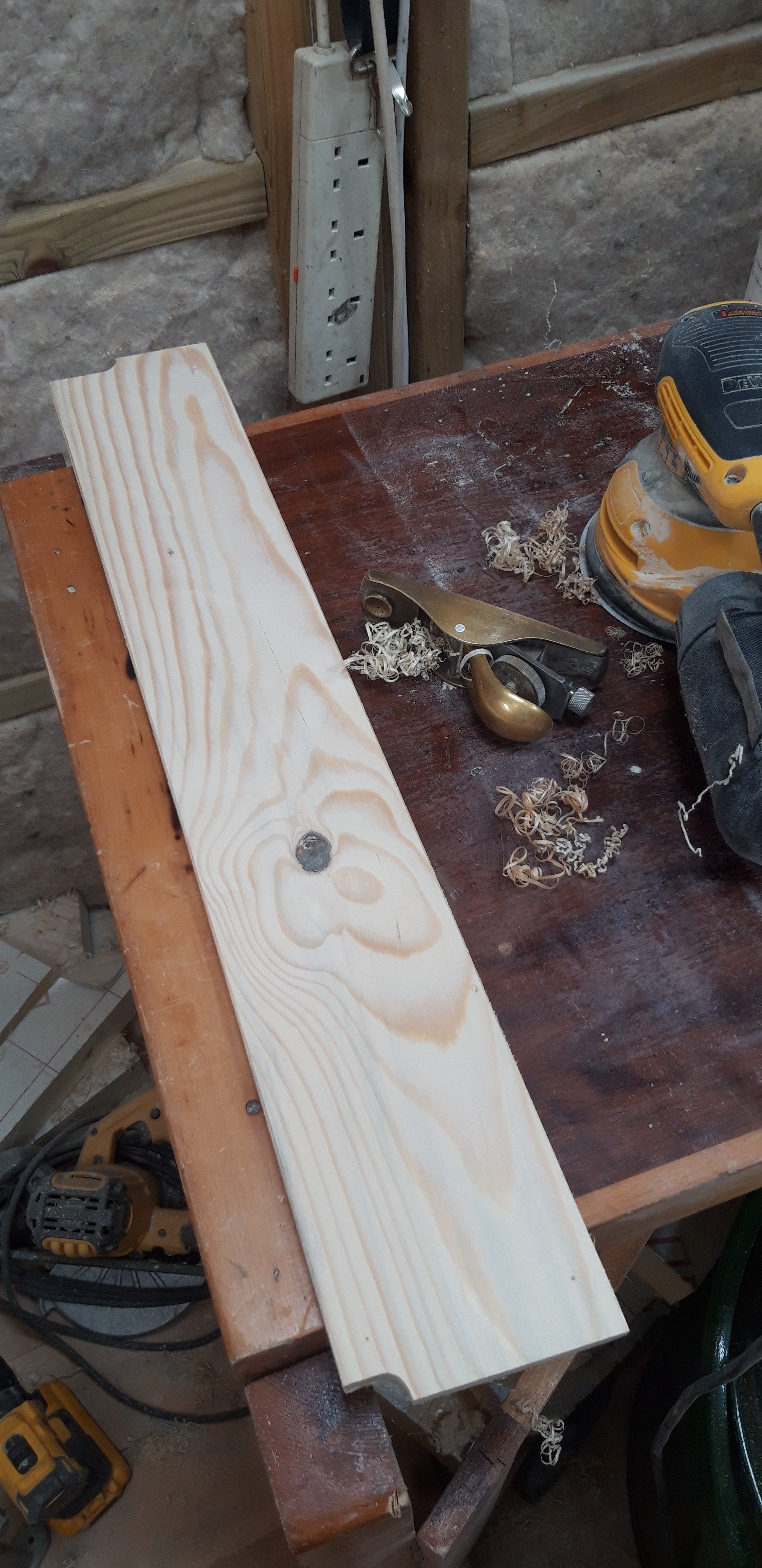
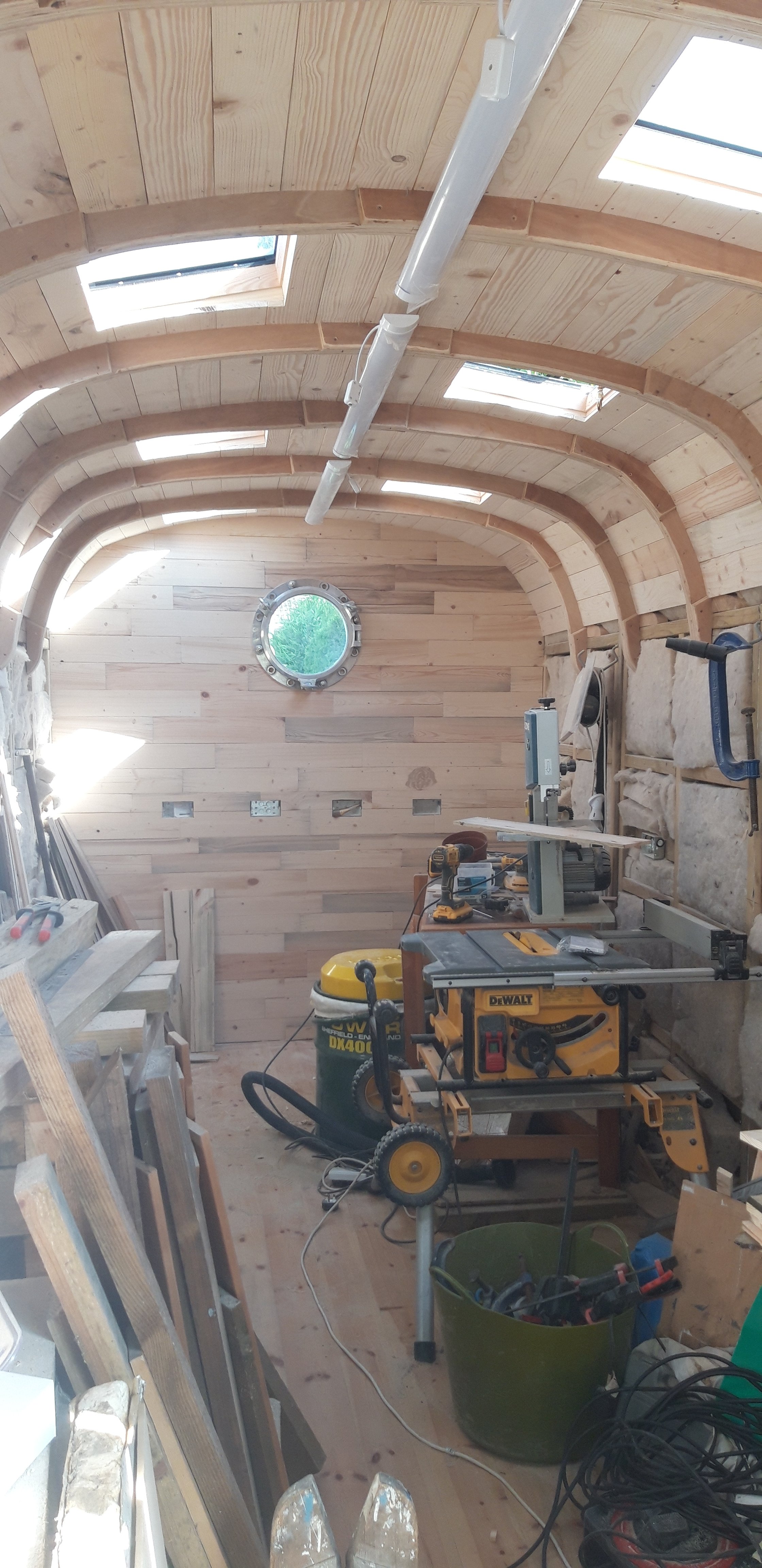
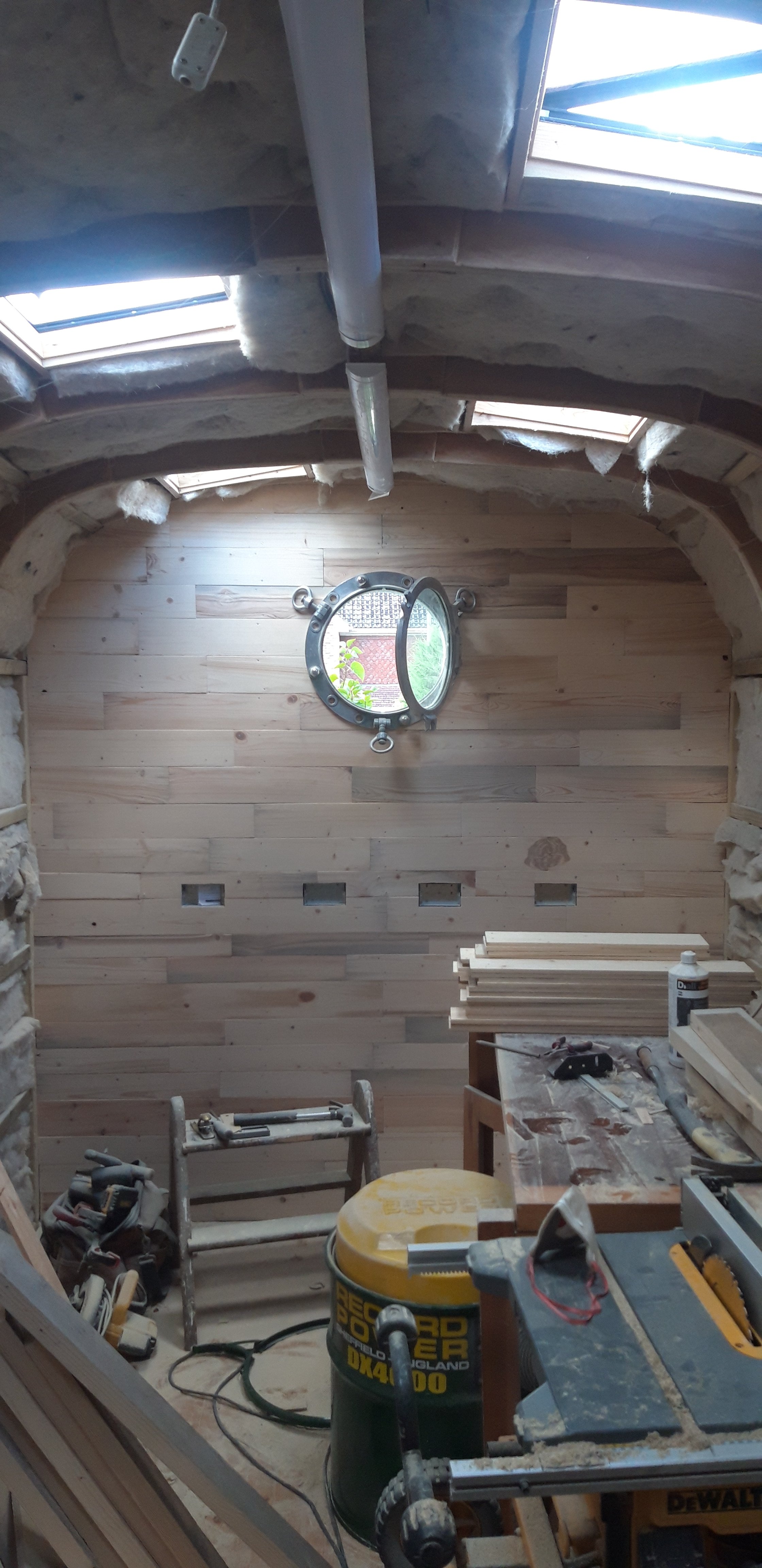
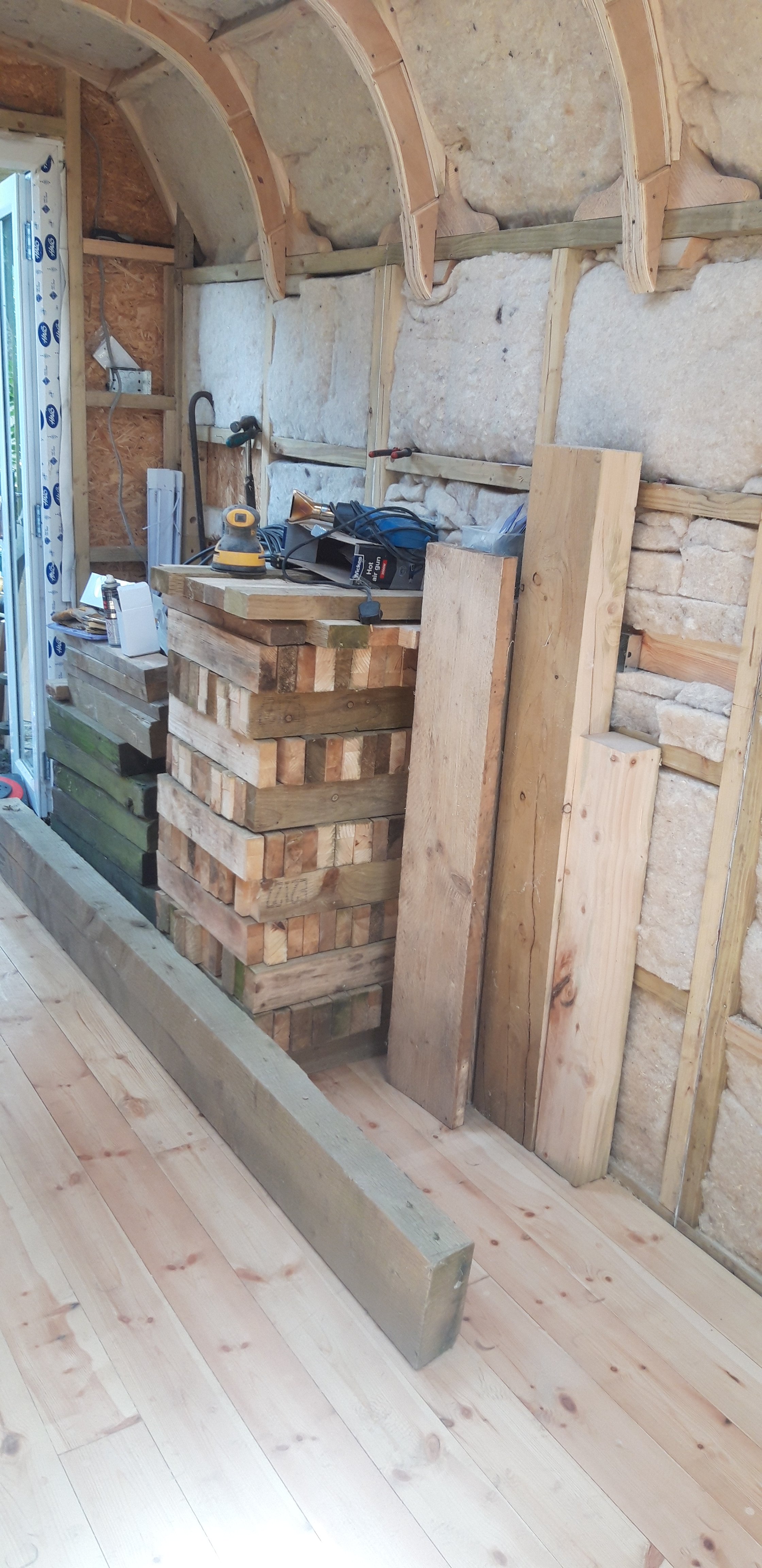
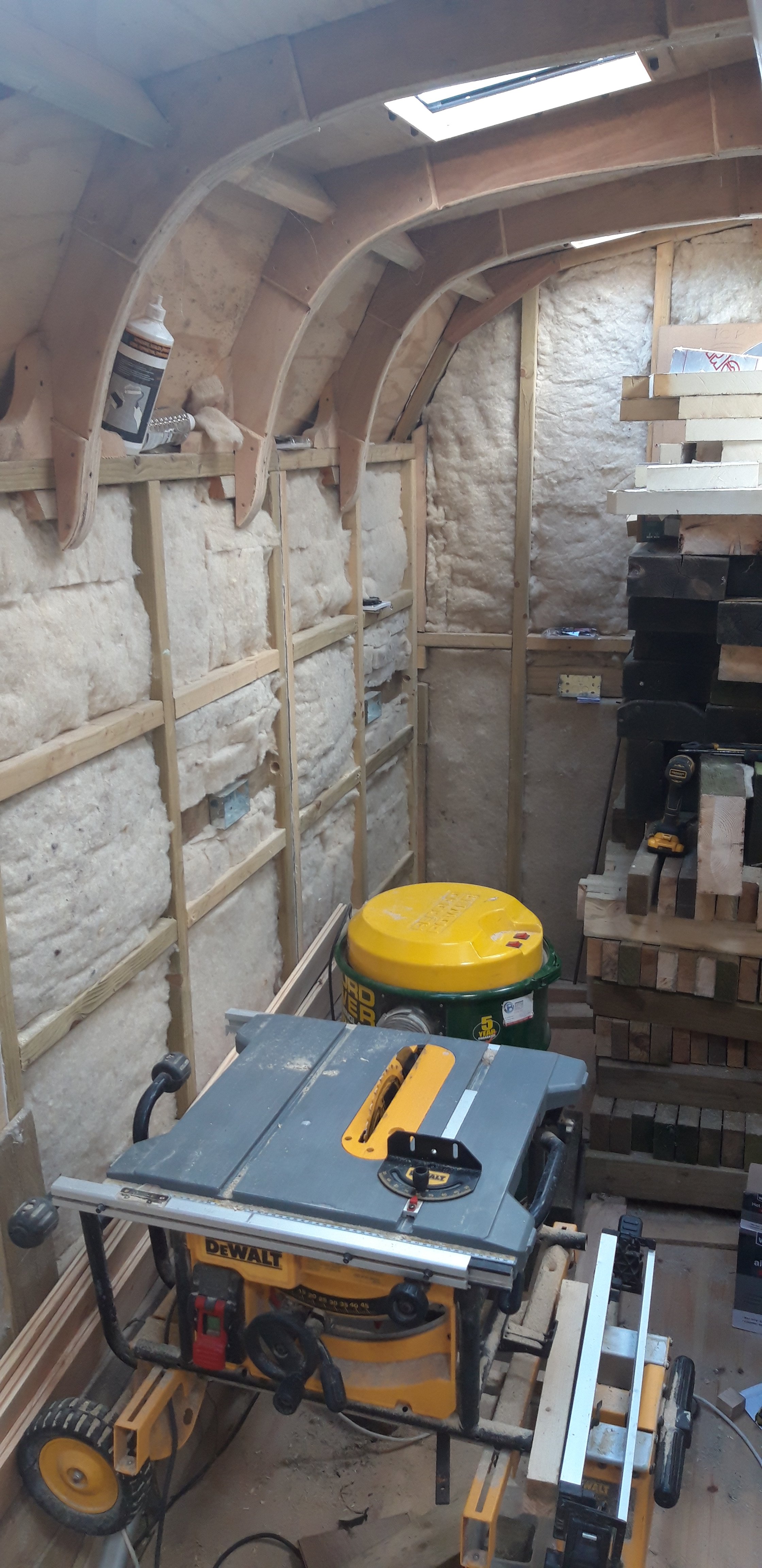
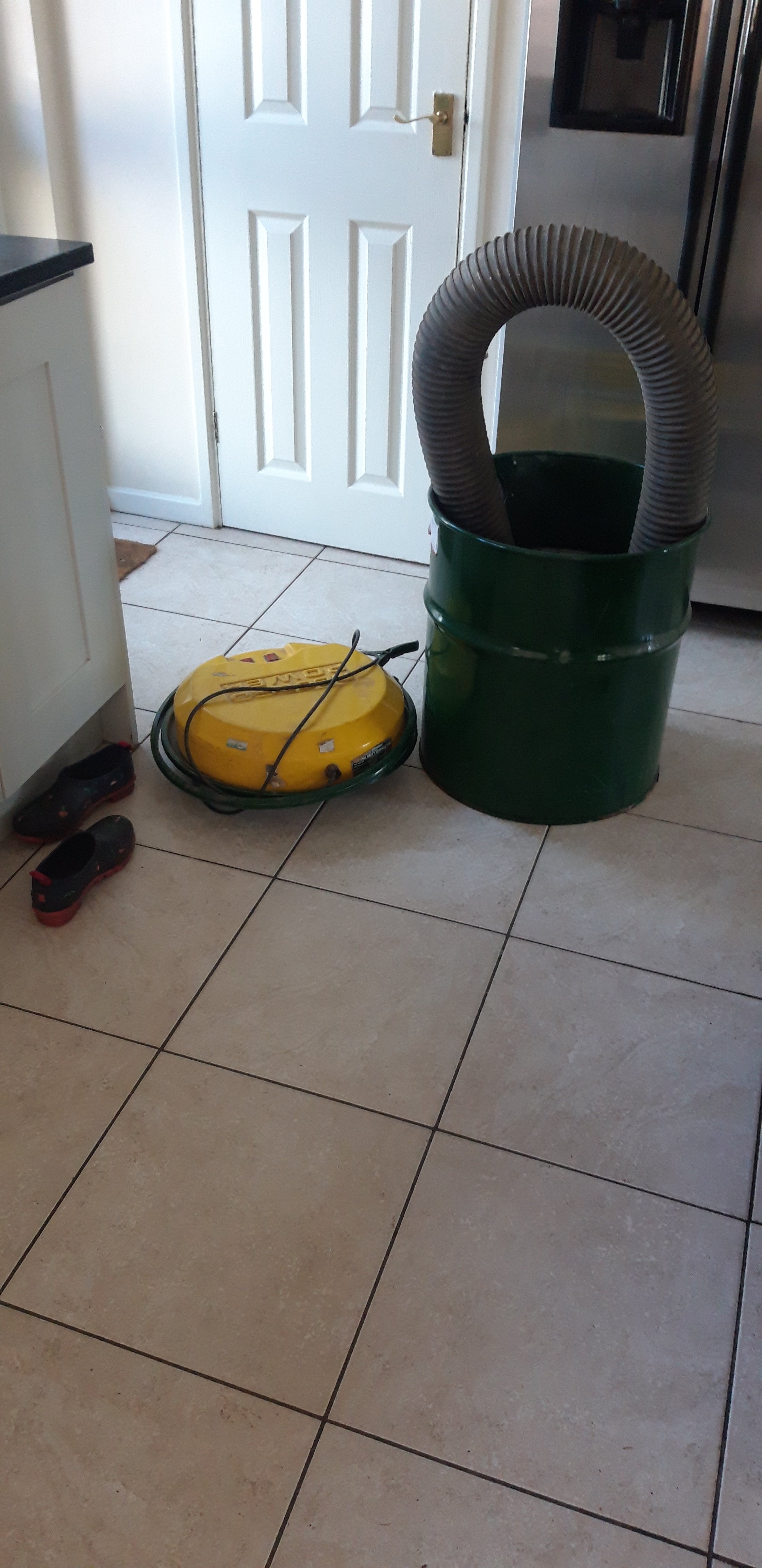
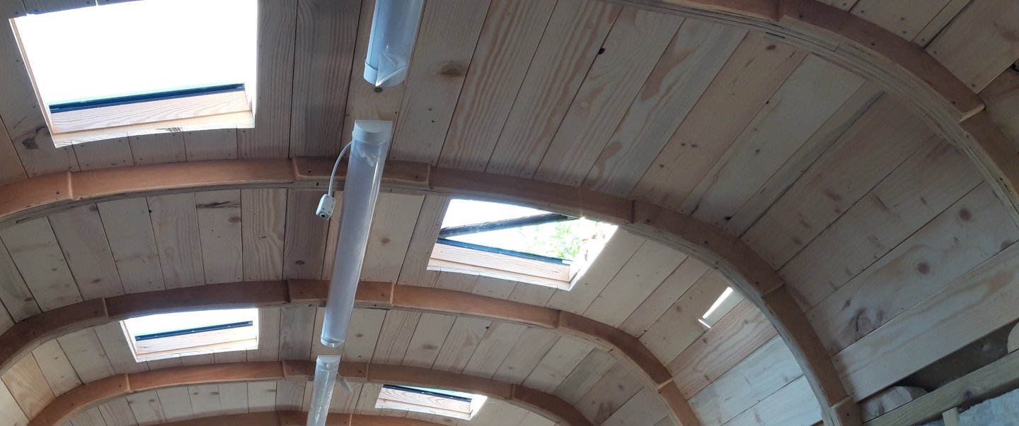
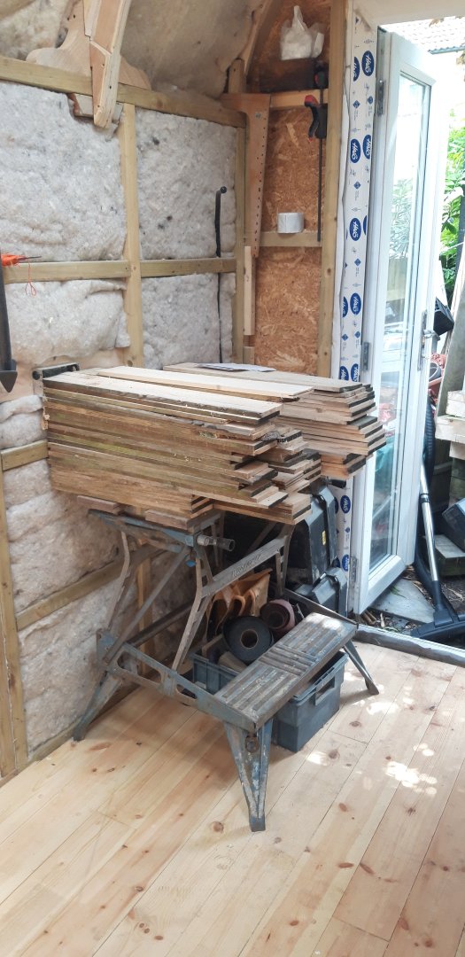
Thanks for that Bob. Some more progress. The salvaged scaffoldboards yielded enough usable cladding for about a third of the ceiling, and scavenged wood, including a section of heavy duty fencing, enabled the ceiling to be completed. Because of the unusual geometry of the workshop with its tapering width the shaping of each piece of cladding was not staight forward. The ends were never 'square', but at least the 2 - 3 degree angle was pretty consistent throughout. Added to this some pieces needed shaping around the ends to match the profile of the additional bracing on the corners of the roof beams. Defects from the sawing etc. were sanded away, and the side corners bevelled with a block plane. The pile of timber bottom left is now about to be converted to the cladding for the walls. Took the opportunity to overhaul the dust extractor with new filters and added the optional cloth filter. It's doing a sterling job. Wish I had a thicknesser.......it would certainly speed things up a bit! Cheers, Graham

- 89 replies
-
- 13
-

-

-
🤫 it has been known for the smallest layout possible, just over 90 cm long, to be connected to a Roco z21 control unit while the Admiral disappears to pilates on a Saturday morning......😉 Model trains are Grandson/Grandpa activity in this case, and for the younger member of the team a source of great fascination and focus. You're so fortunate to have that shop so close, Ron, but I can see the danger of tempation! My two closest stores have shut in the last year so purchases are usually made on-line, without the chance to look, handle and seek advice from the staff. I hope you will keep us updated with your layouts' development and evolution. Cheers, Graham.
-
Great work Ron. Your advice on the best sequence for adding the hammock cranes has been noted, thanks! It's all coming together nicely. Will you be adding the netting on the bow section where the knightheads are mounted? Like that other hobby too.... N gauge? An impressive layout and the work under those bridges is intriguing. I'm just starting to get involved in model railways as well. Early days, but a totally unexpected Christmas gift from the Admiral of an Accurascale OO gauge class 55 Deltic locomotive (one of my favourites) provided the spark, and I'm working on getting to grips with DCC controllers etc. The gift came with a proviso, however - no building a layout until Victory has been completed 😄.
-
Thanks Ron. Your mesh corresponds pretty much exactly with what I thought it needed to be, which is 2 mm across the corner to corner diagonal of each hole. The problem I found with a lot of the tulle fabric available is that it appears to be a hexagonal pattern, and often the pictures of samples in suppliers advertising material are taken so far away that the size and pattern is hard to see. Definitely need to see it first hand before buying! The hunt for mosquitoe netting in the UK begins..... Cheers, Graham.
-
A quick question Ron. What size is the mesh on the fabric you have used? It's something I've been looking into in preparation for these hammock nets. I've been researching tulle netting but struggled to find a square or diamond pattern that matched my calculations. Been away from the 'shipyard' for a couple of weeks but hope to get back to building in a couple of days 🤞. Cheers, Graham
-
Looking very good Ron! That mosquito netting really looks the part.
-
I decided to go ahead with my original plan and used the pieces of cladding I had already prepared to trial the idea on the far end wall. 'Loose tongues' keep the ends of the boards level where joints don't line up with the timber frames. The width of the cladding strips vary between runs, and the run that follows the line of the sockets is only temporarily tacked in place so that it can be removed to permit the installation of the ring main cable. I'm focusing on the ceiling next and am currently converting those scaffold boards used as shuttering for the concrete base. Thinking of possibly giving the internal cladding a 'limed' or whitewash effect finish that makes a feature of the wood grain. This will then be coated with satin or matt varnish. We'll see... Cheers, Graham.

- 89 replies
-
- 18
-
-
Lint free cloth will do the trick for application. Just a thought, might be an idea to just apply the oil to the the draw fronts, avoiding the carcasses. The oil should definitely bring out those warm tones you're after. Looking forward to seeing the results!
-
Hi, Great work with the desk! An oil finish should work well, but test on a piece of scrap first! Tung oil can be thinned with white spirit (or turpentine). Have you thought of trying Danish oil? It contains some tung oil, but I find that it drys more quickly. Some brands of tung oil I've used in the past seemed to take an age to get past the tacky stage.... Good luck! Graham
-
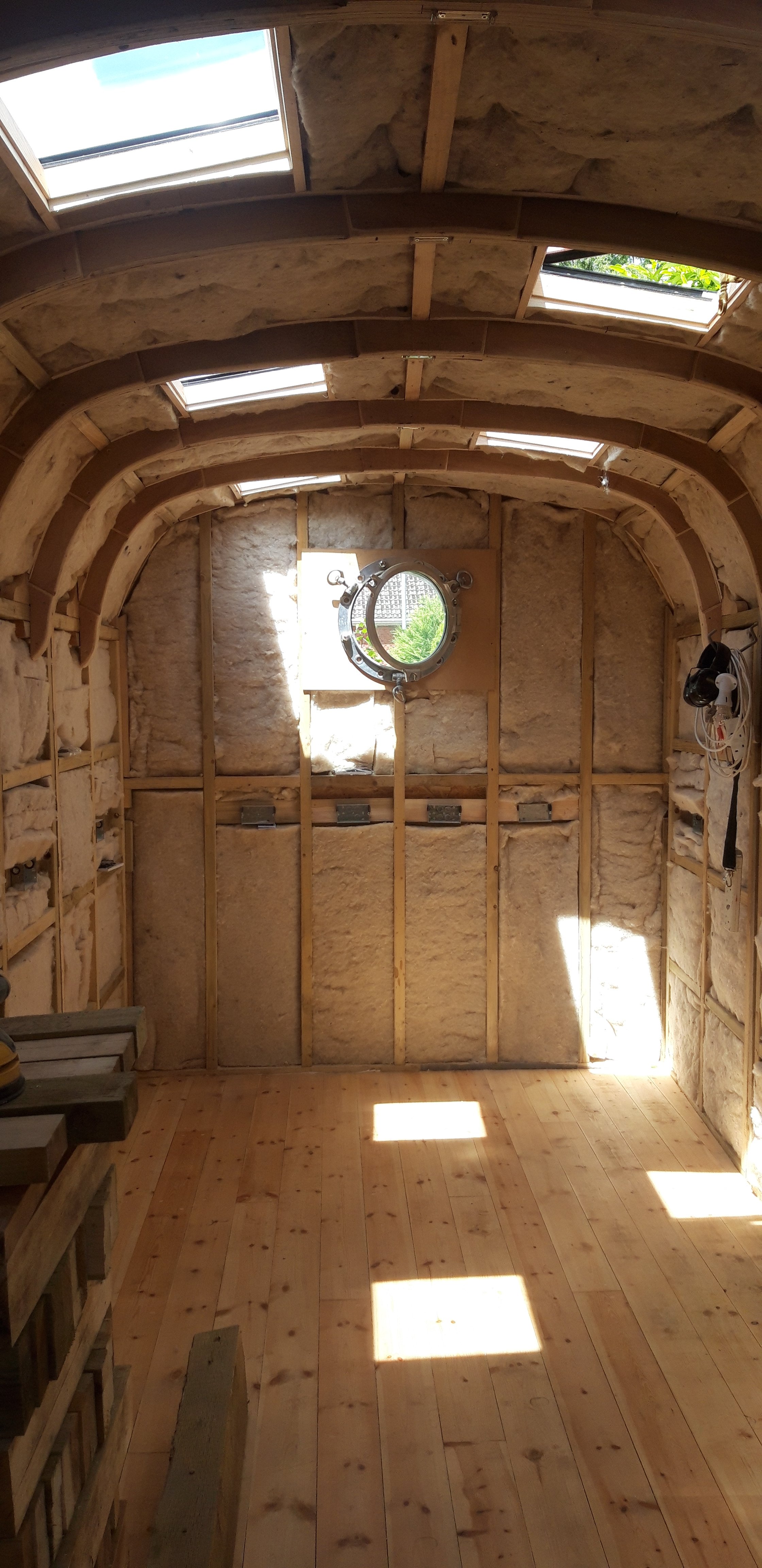
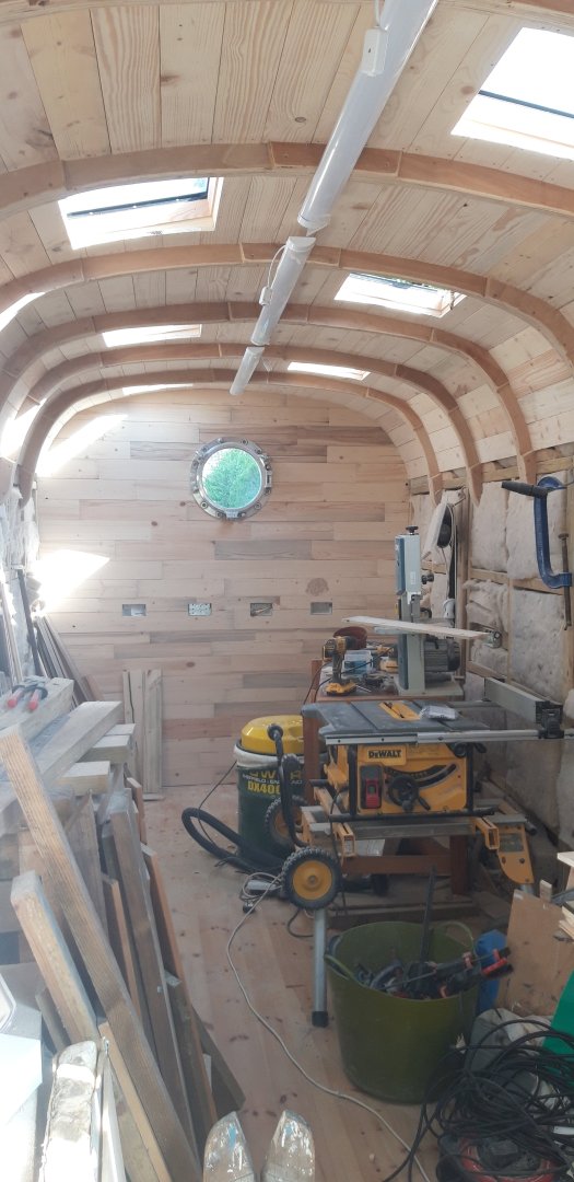
A big thank you for all the 'likes' and advice I've received. Summer has final arrived with the local weather producing temperatures in line with those expected in June. The opening porthole, together with the single opening roof light, and now with the insulation in place, have produced a very comfortable working environment. There's definitely a light and airy feel to the place, especially in the end that will be dedicated to model making. Getting there slowly..... the end is in sight now
- 89 replies
-
- 11
-
-
Thanks Ron. We also know it as plasterboard. Joints will need taping, and the walls given a skim coat of plaster. I have used this in the past. Still looking at the finances however......Decisions, decisions....🤔😁 Cheers, Graham
-
Thanks Javlin, I certainly look into this sheetrock. Cheers, Graham
-
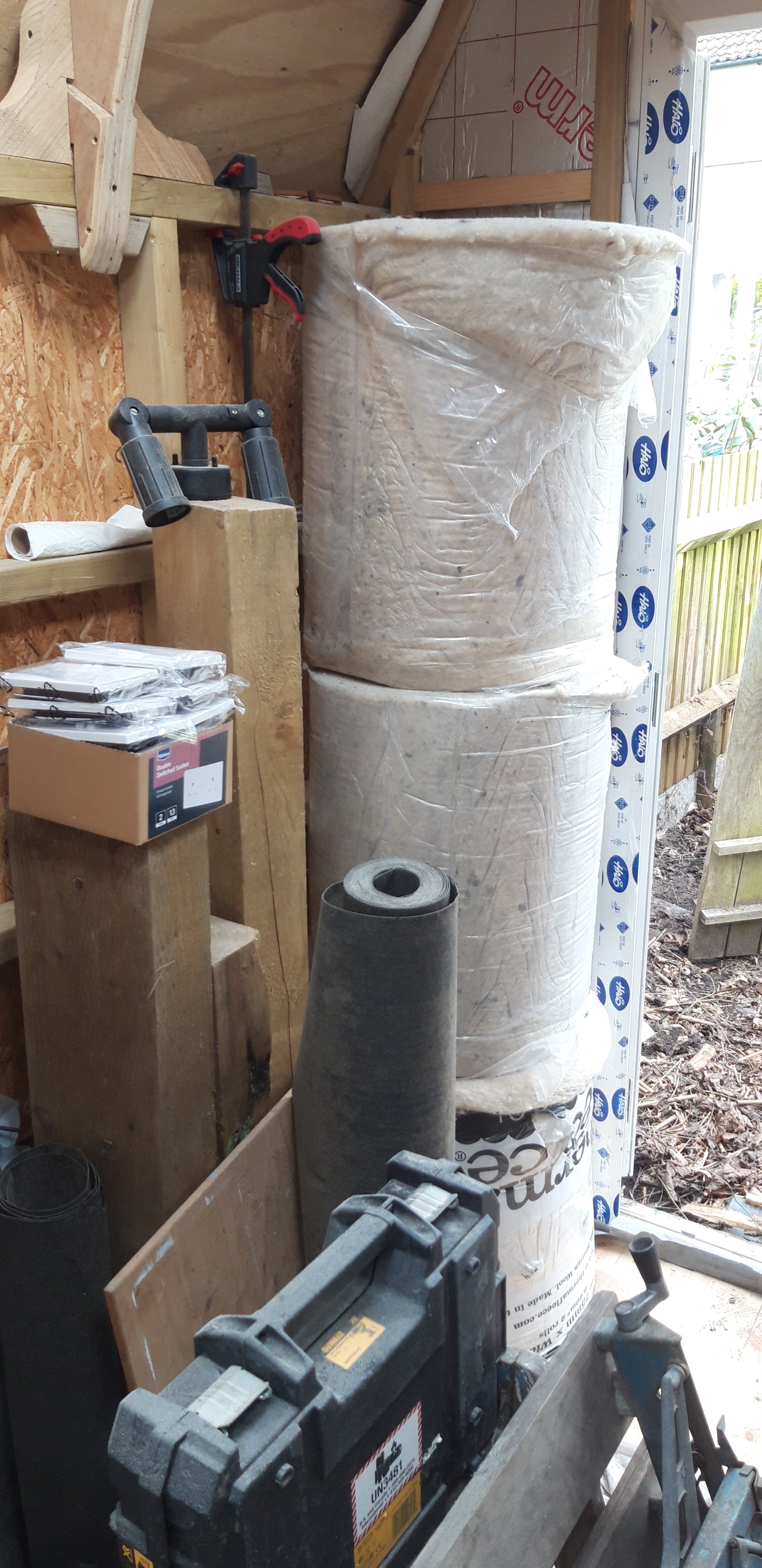
Now that was an idea that hadn't occurred to me Kauz! Good call... More progress... After the promise of foam board insulation sheets at a bargain price evaporated into the ether, I decided to opt for a sheep's wool based product that would more effectively address the issue of both temperature and sound insulation. I also managed to start sourcing the components for getting power into the workshop. I'm not qualified to do this aspect of the build myself, but fortunately my brother-in-law is! After a long career in this profession his knees are suffering even more than mine! As long as I get the donkey work for the first fix done, he'll come over and do the clever stuff. Under his guidance I have run, but not connected, the correct size cable from the fuse board to the back of the house, armored cable from there to the workshop, and all the patrice boxes fitted in place for the sockets and switches. The LED strip lights have also been fitted and await his professional touch. My original plan was to clad the walls with MDF, with routed grooves to look like T&G boards. Not able to fund this method now but I have a plan.... I have a stock of pine 200 x 100 sleeper off-cuts from a previous garden landscaping build plus the timber shuttering left over from pouring the concrete base. My aim is to convert this into suitable cladding material... There's a lot of sawing to do so my extraction system was recovered from storage to reduce the dust levels this work will produce Conversion has begun and I will shortly trial this on the far wall. I have added some additional framing to the roof beams to provide something to fix the cladding to which proved a bit of a challenge. I want to keep the laminated beams visible and just add cladding between them. The end result will hopefully be sort of modified barrel vaulted ceiling......we'll see 😁... Cheers, Graham


- 89 replies
-
- 12
-
-
Great to see your Victory finally completed and displayed Robert. That is a truly elegant display case that really does the model justice. Love those three supports, and as for the lights.....! Thanks for sharing so many tips and suggestions throughout your exemplary build log. I have found, and will continue to find, your detailed work an inspiration. Good luck with those cameras. I too am a Canon camera user, with my old SLR A1 tucked away safely together with the EOS 20D that replaced it - pretty humble compared to modern models, but it got me through the transition to digital😄! Cheers, Graham
-
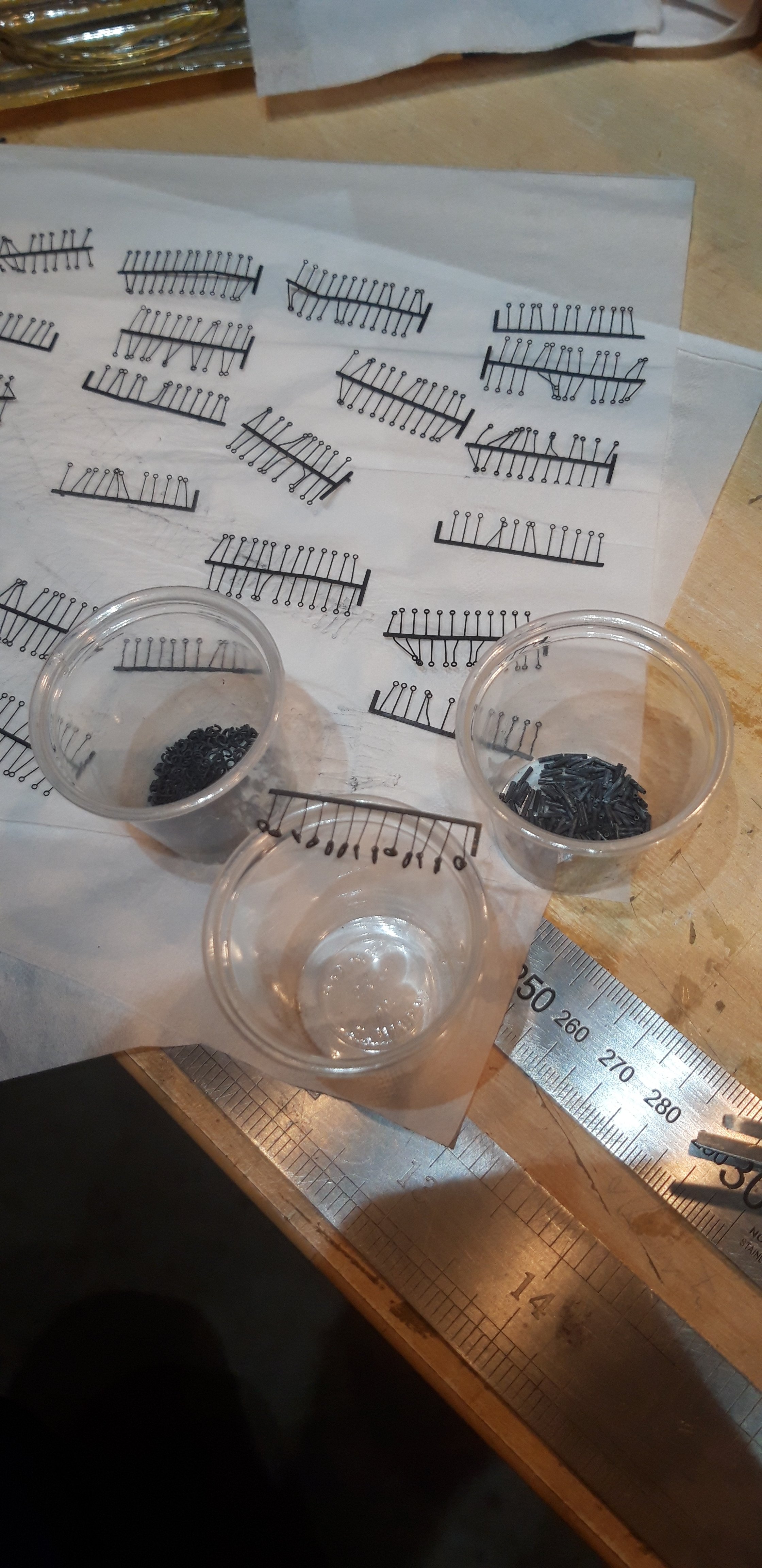
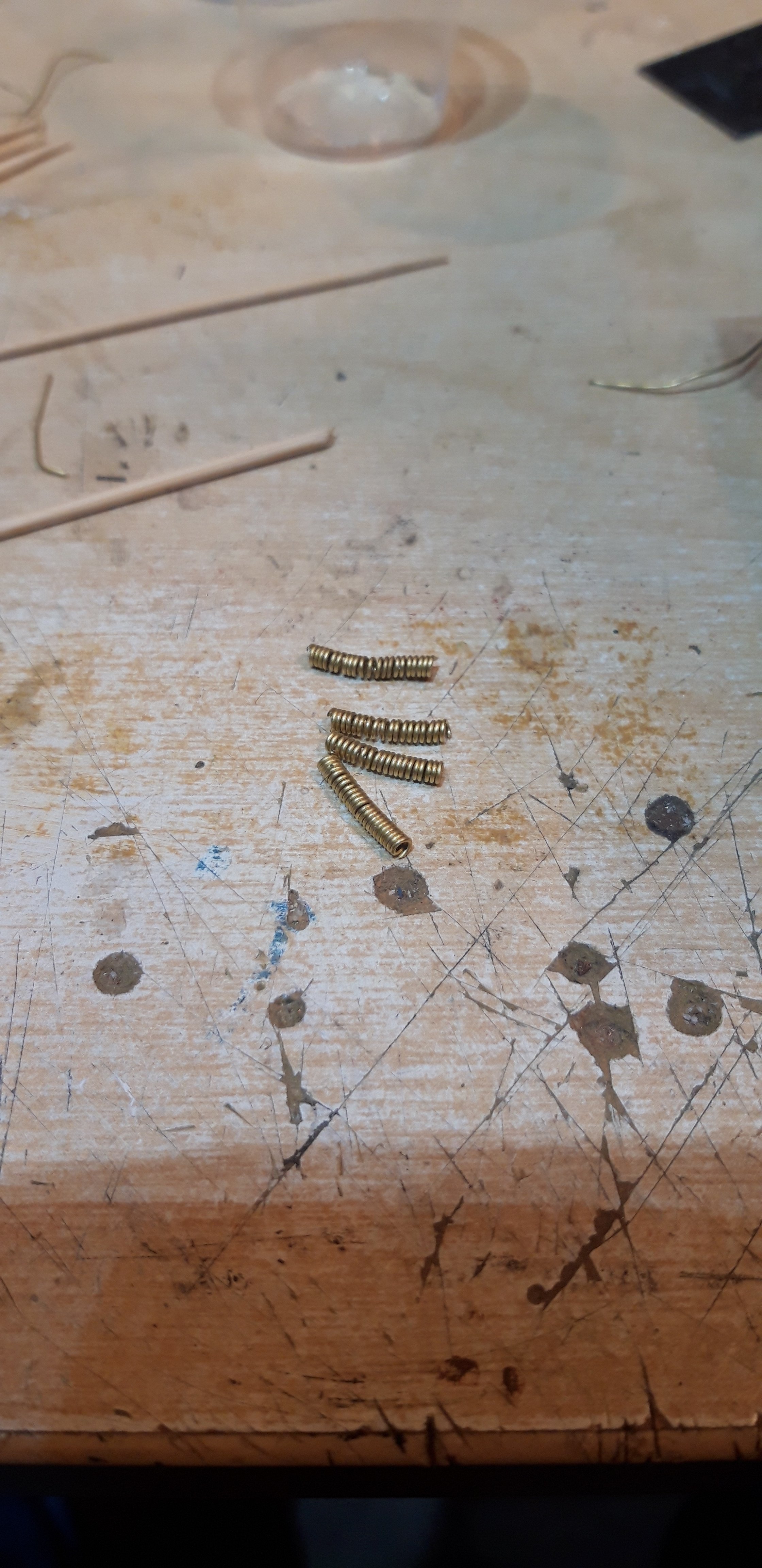
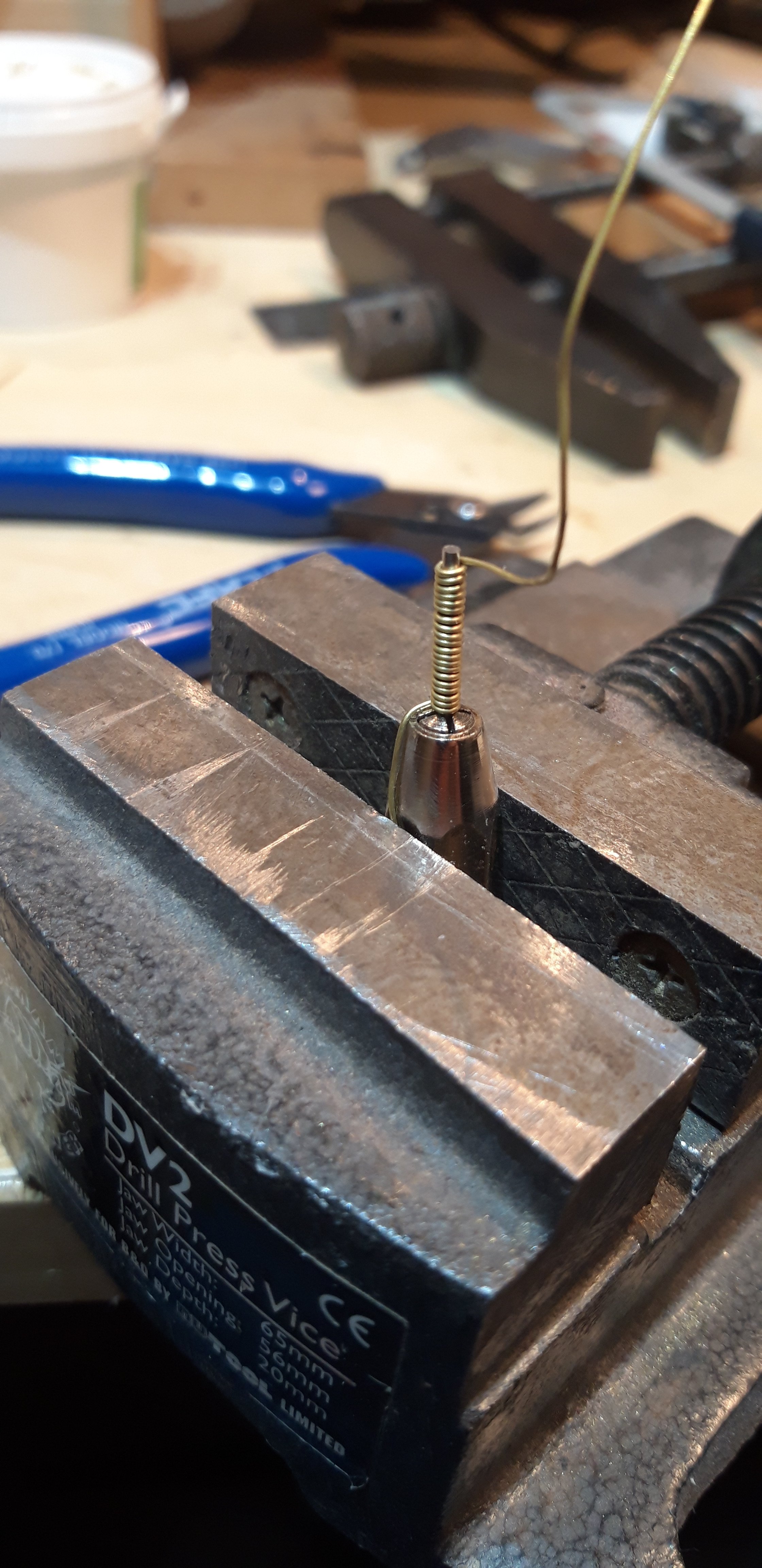
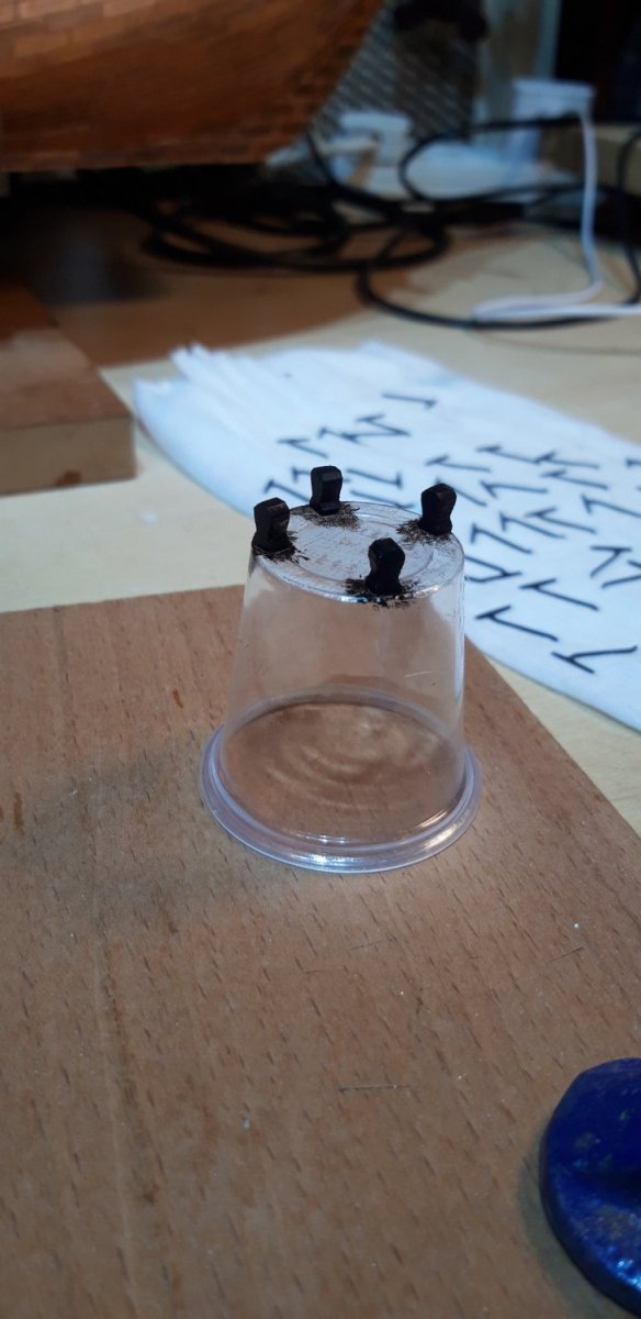
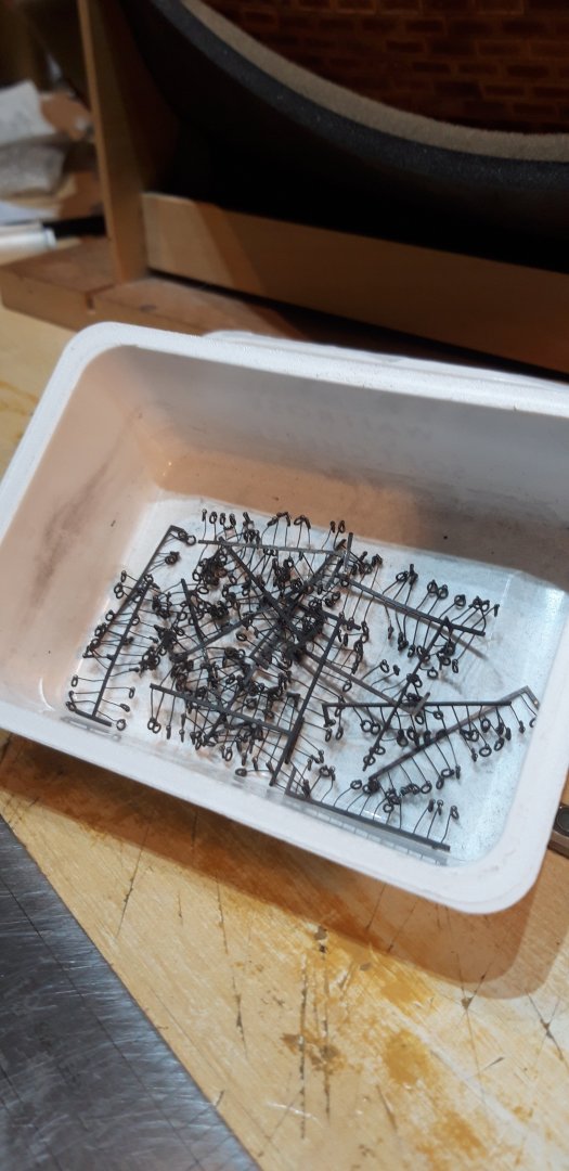
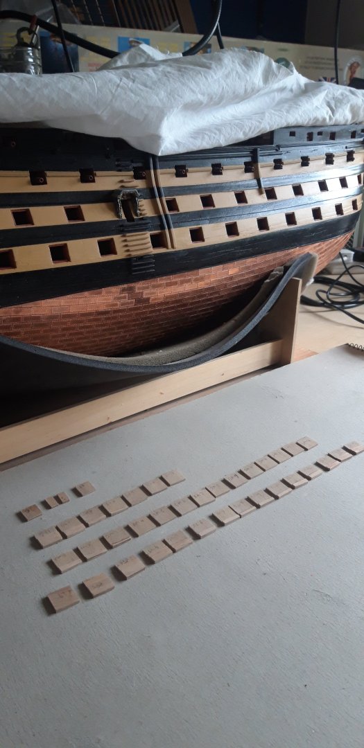
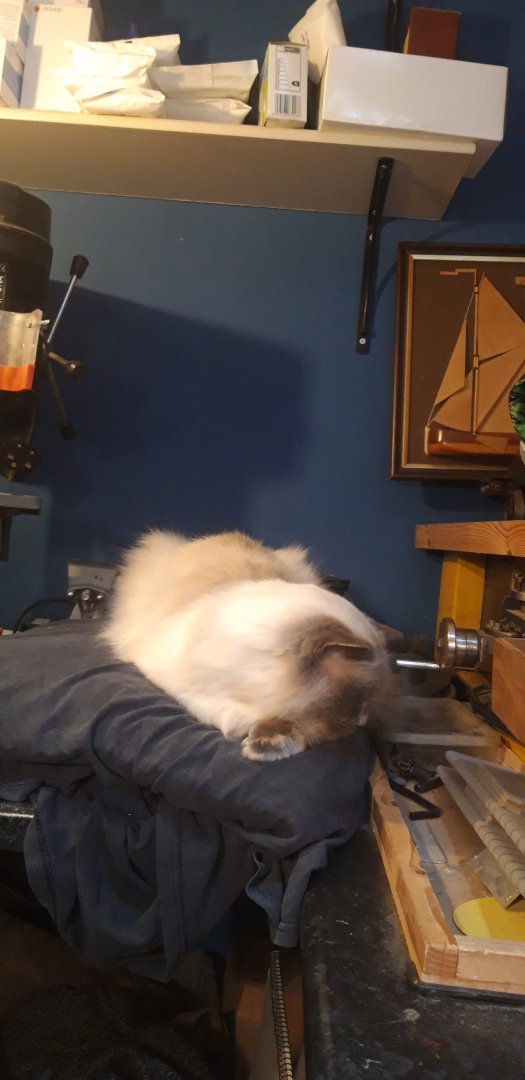
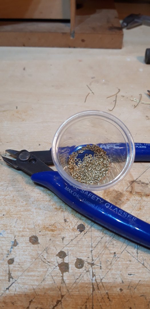
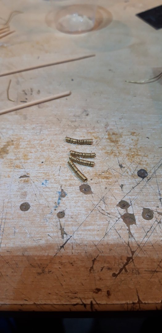
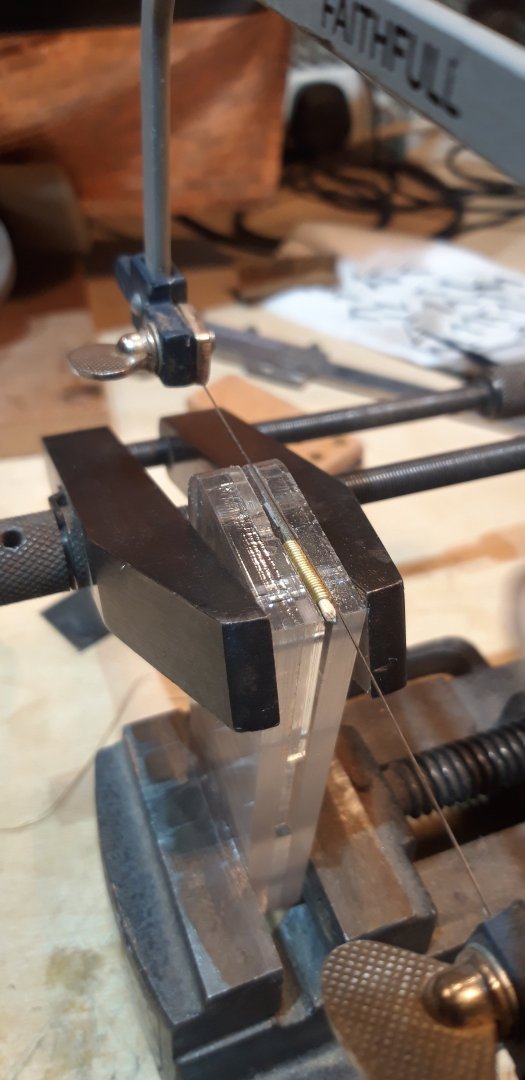
I've reached a stage in this build where several activities need to be prepared and organized before the primary task of fitting the channels and chainplates can be done. There are five gun ports on each side that I'm guessing would be best done first as they are below or very close to the channels. There are also the pairs of holes to drill above each gun port and the distance between these is determined from the hinges on the gun ports. Rather than just make and fit a few gun ports it seems that now would be a good time to make them all although most will be fitted after the main rigging has been done. To complicate things even more I want to follow Roberts excellent idea for adding the rings inside and outside of each port. First step then, making these rings. 0.5 mm brass wire was wound around the shank of a no.56 drill bit giving an internal diameter of about 1.2 mm. Cutting these into individual rings was initially tried with an acrylic clamp and a piercing saw Moderately successful, but I finally resorted to using a modified pair of cutters. These rings needed blacking as did the eyelets they need to be fitted to. As the work bench was set up to do this I also did the 1 mm diameter tubes that will guide the port ropes. Fitting the rings into the eyelets was straight forward, but a bit tedious so cleaning up the port lids and building up those that overlapped wales was done to break things up a bit. Approximately 350 rings, allowing for spares... and the starboard lids.. Hinges etc. will be added once the port side ones are done, and then they can be painted, and the distance between the guide tubes measured. I know these will be 6 mm above each port.... think it will be time for yet another jig to help with accuracy and consistency... Another slight modification. I decided to drop the height of the two foremost painted ports to give more room for the rigols And finally.... it seems I've been adopted... meet Bertie... He is not our cat, he lives in the next street, but he 'owns' the neighbourhood and is frequent visitor to our front garden with its better sunny steps and shady corners than available at his owner's property. He sometimes sneaks in and has recently taken to keeping me company. Seems we share the same taste in radio station and he fines the hum of the disc sander conducive to a quiet nap..... Cheers, Graham.


-
Impressive work Ron, and I too have had to make a few compromises along the way when trying to get things to line up and work out (approximately) as shown on the plans.....if only to preserve my sanity🤪. Sometimes you just have to accept things and move on. More often or not we, the builder, are the only ones who know....🤫😆
-
Impressive work Craig, especially the challenging task of marking, cutting and lining those gun ports! As you said in your first post, filler and sanding is definitely often your friend and has certainly helped me out on numerous occasions. Coming up with jigs and other aids to assist in achieving accuracy is an aspect of model making that I enjoy. I'm currently thinking through a way of drilling the two holes above each gun port for the supporting ropes. Unfortunately I no longer have any access to those well equipped workshops, and in particular the software and laser cutter that I used to make many of those simple tools.... but I have a plan..... I'm getting closer to finishing my home workshop at the bottom of the garden. The insulation arrived last week, the electrical supply has been planned and the fittings etc. are being sourced as funds become available. I have also successfully experimented with a way to clad the internal walls using recycled (and free!) wood. I'll be updating the build log for this in 'Shore leave' when a bit more progress has been made. In the meantime there's plenty of prep work to keep me busy on Victory. Looking forward to watching your build, you've clearly made excellent progress so far 👏😁
-
Hi Craig, Covid certainly changed things and its impact on you clearly brings its impact into perspective. Sorry to hear you lost your business! From a personal point of view it caused me to make the difficult decision to retire earlier than planned from the rewarding 44 year plus career I loved. With no proven medical solutions at the time, some students idea of meeting safety protocols being to rub their hands together to give the impression that they had sanitized on their way onto the school site as they bypassed the measures provided for their protection, and the stress of trying to deliver a genuinely high standard of education in my chosen field of Design Technology and Product Design remotely when classes were 'closed' and isolated due to infection, I relented and accepted the Admiral's advice to put my own health first for once and to hang up my workshop apron a year earlier than expected. Teaching a practical subject when the workshop facilities were unavailable, lessons were delivered in classrooms normally used from anything Science to Geography or Music definitely had an adverse impact on mental health. As for retirement, it's definitely not as expected and I still look forward to the time when I can fully enjoy it.... I can honestly say that I have never been so busy! Grandchildren, and the Admiral's house and garden projects make me long for those happy halcyon days when returning to work on Monday morning brought an illusionary opportunity to relax a bit! But we move on, the world has definitely changed. The photo in your post is impressive and intriguing and I look forward to hearing and seeing more with eager anticipation....... no pressure 😄 Cheers, Graham
-
Nice, very nice Ron. I found the bow and stern the two most satisfying stages so far.... Well done!
-
Well spotted Ron! The four timberheads, parts no.179, have now been cut out of 3 mm walnut sheet 1, cleaned up and painted ready for installation tomorrow together with the recently blackened channel brackets.... Cheers, Graham

-
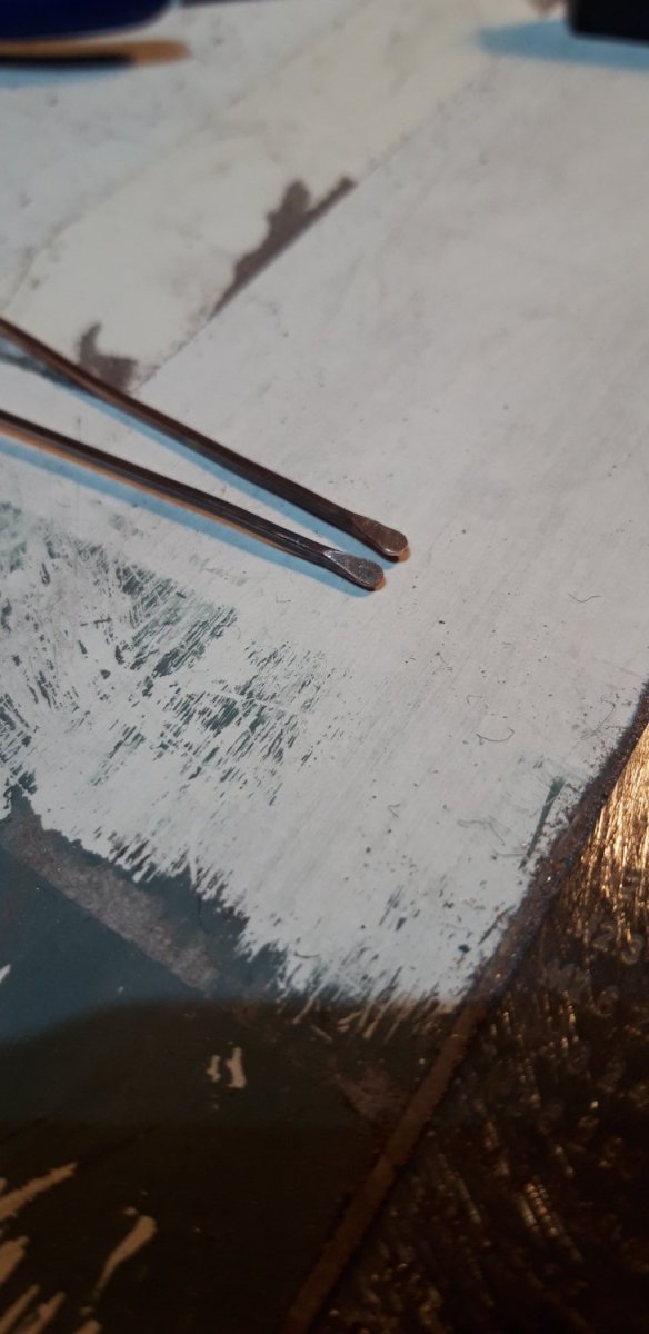
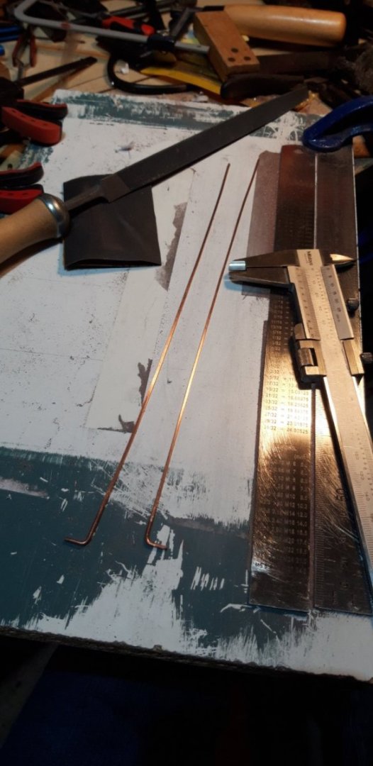
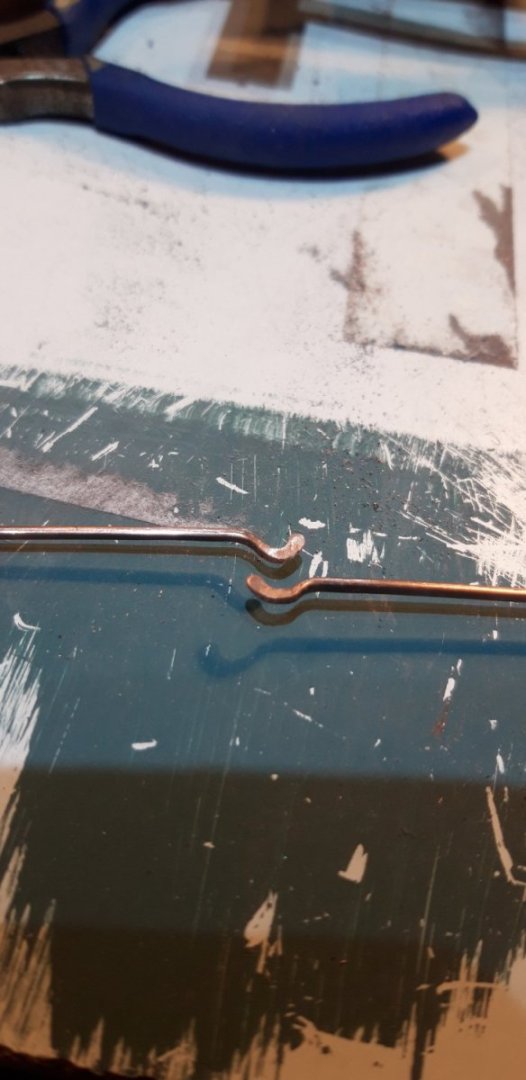
Thanks for following my contributions and giving them a 'thumbs up'..... Robert, it is a great motivation seeing the inspirational work of the master craftsmen on this site whose build logs have helped me through many of the challenges that have arisen. It certainly pushes me to try and improve my own skills. It is really important to study the plans Ron, those brackets aren't the only instance where the written instructions don't give the whole story. It just happens that it was the case with the next task I tackled. On the same plan sheet (5) there are details of the decorations on the outside of the bulwarks. I cannot see any reference to how these are constructed in the manual. The parts manual shows parts 412 and 413 listing them as Moulding 90 degree and Moulding termination foot respectively. They are on the second sheet of 1.5 mm walnut. There is no information on what to use to use with them. I assume it should be 1.5 x 1.5 walnut strip. When I added the inner bulwark decorations I used copper wire scavenged from a bit of twin and earth electrical cable (post #84), and I decided to go the same way here, discarding the wood for metal. This took me back to those lockdown days when I made the inner decorations. Travelling to a modelshop for materials at that time was impossible so a bit of improvisation was called for. First stage was to file the 1.7 mm dia. copper wire to profile, three flat sides and one, the outward facing surface, left curved. The final thickness is 1 mm. Next step, after annealing, was flaring and tapering the ends in preparation for making the termination feet followed by shaping Pieces were then cut, bent and soft soldered as required. After cleaning up these were glued in place. All this work needs to be painted next. Currently awaiting a delivery of Dull Black and Yellow Ochre from Cornwall Model Boats as my stock, purchased along with the kit many years ago, is showing its age.... In the meantime I'll get those support brackets cut from the PE frames and prepared for fitting. Cheers, Graham.

-
Hi David, Did you use an on-line photo hosting site for your pictures? I used to, it was free and allowed me to crop, rotate and manipulate the data size of images before uploading them into my build log. When they changed their conditions of use and required a subscription payment I stopped using them, and could no longer access the pictures I had saved with them. There were then problems with photos I'd previously added to my build log through that provider. Just a thought...... Cheers, Graham
- 439 replies
-
- 1
-
-
- victory
- caldercraft
- (and 1 more)
-
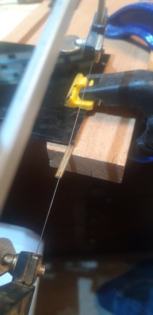
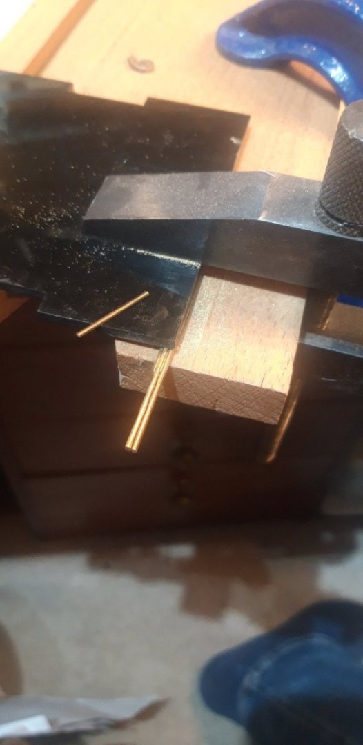
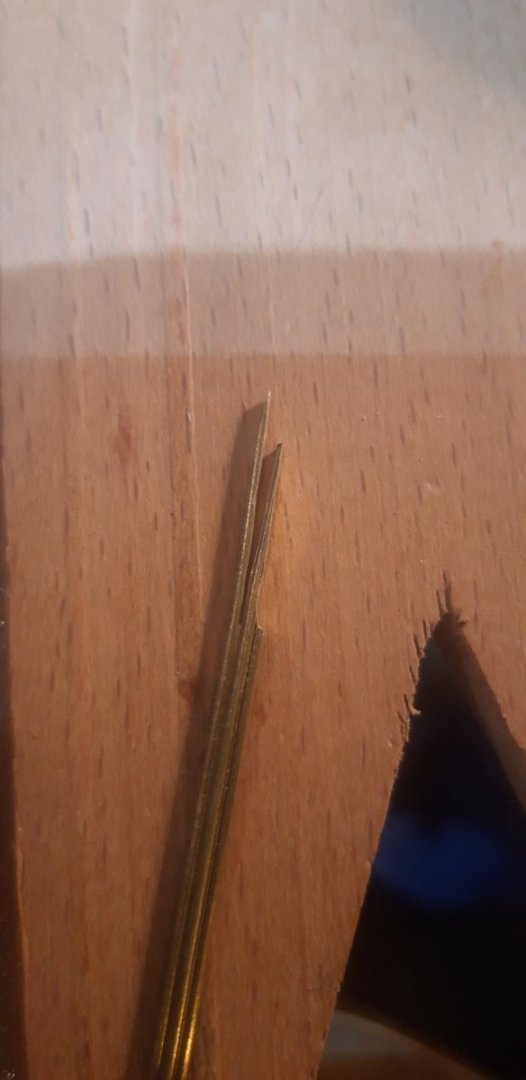
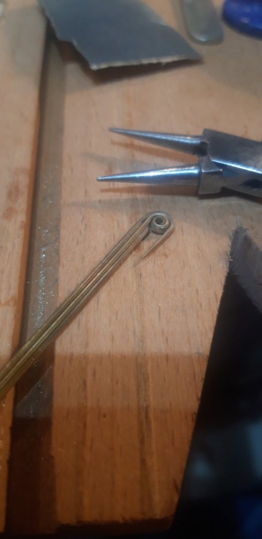
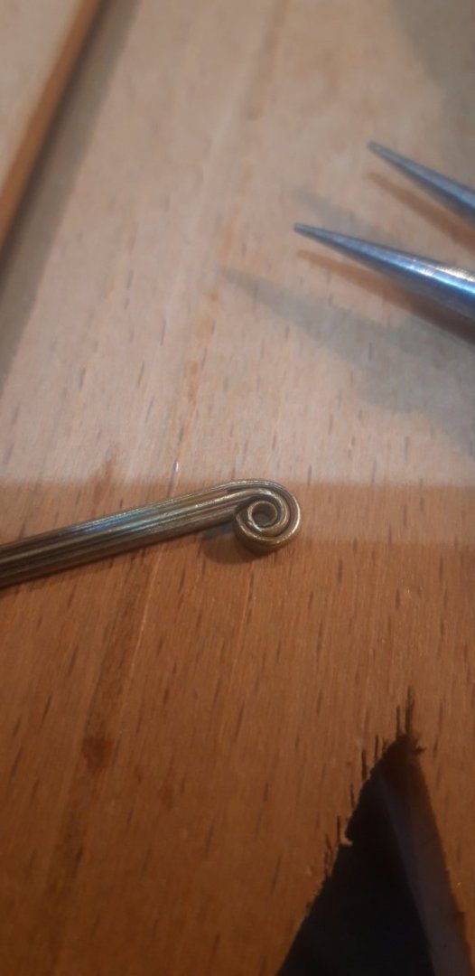
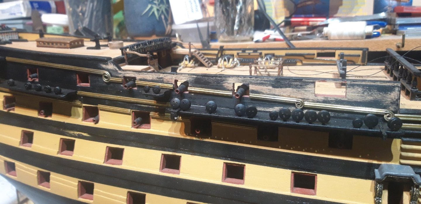
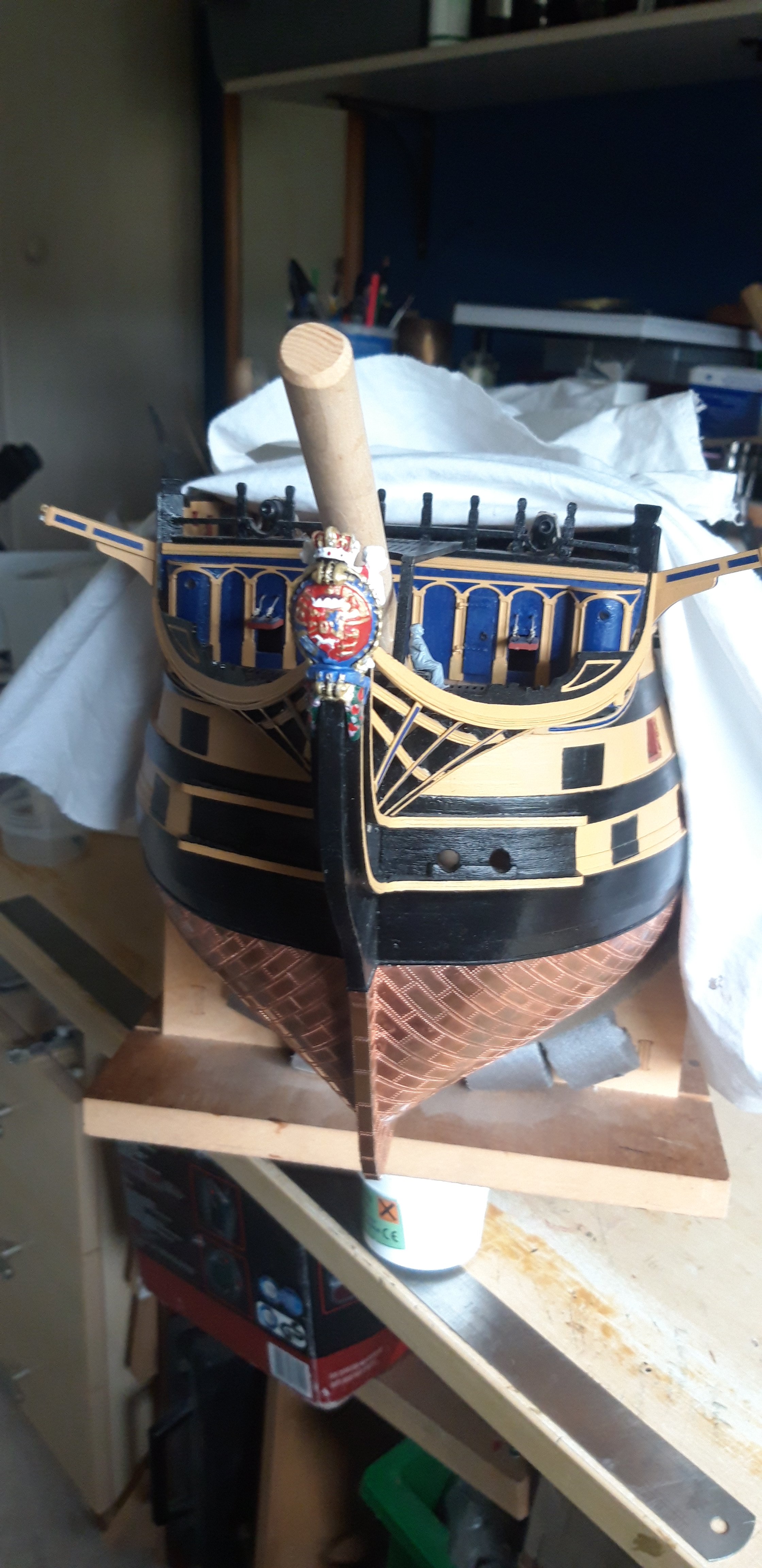
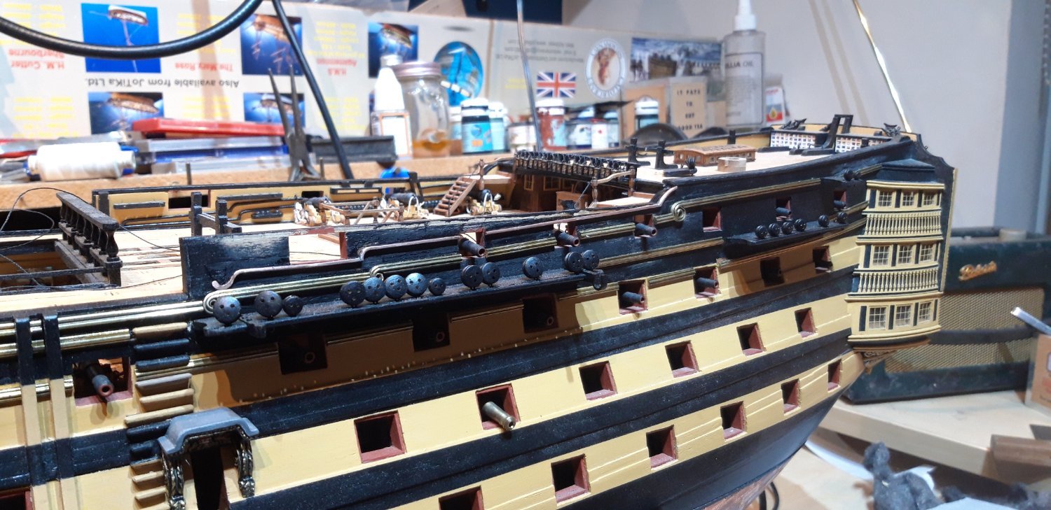
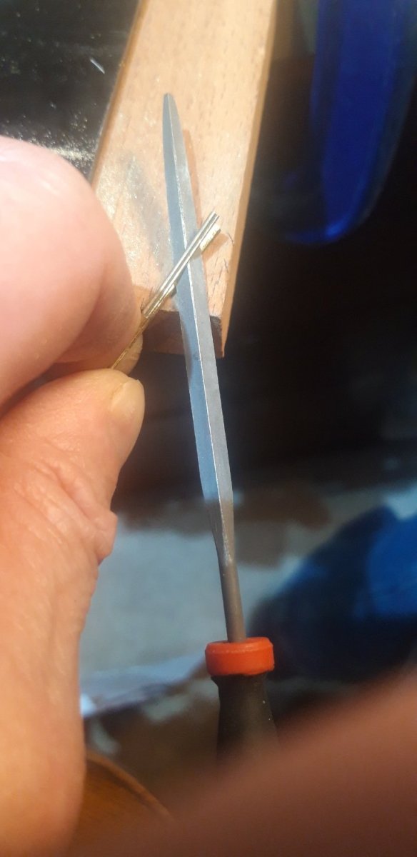
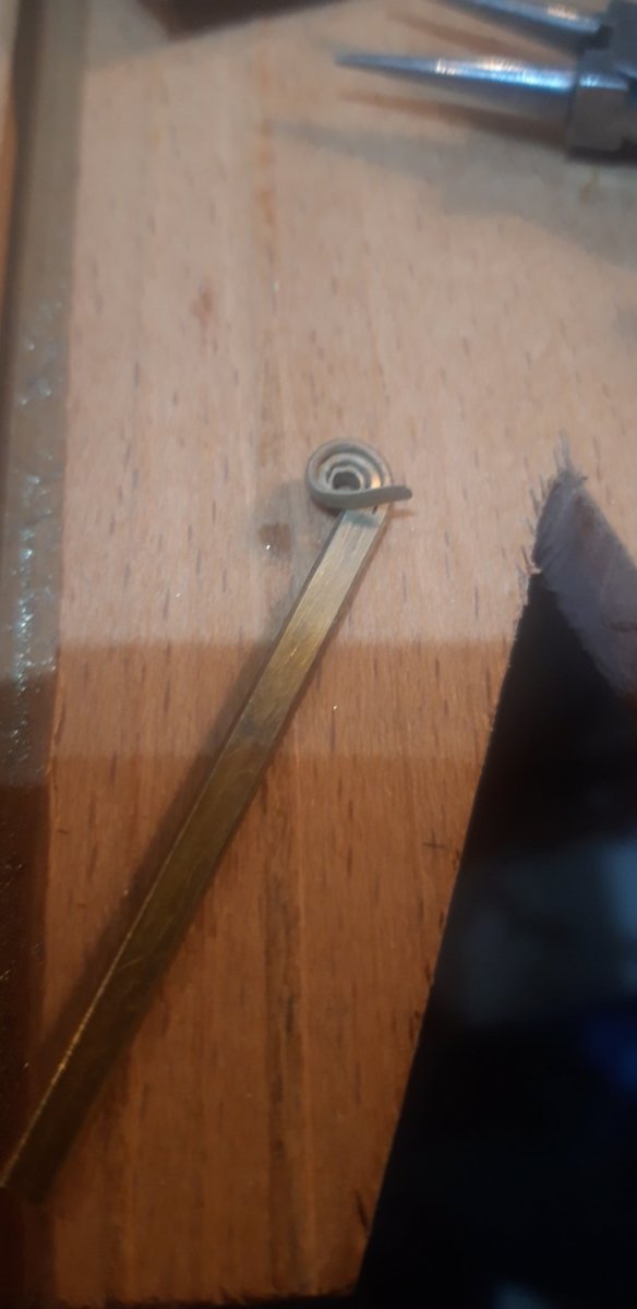
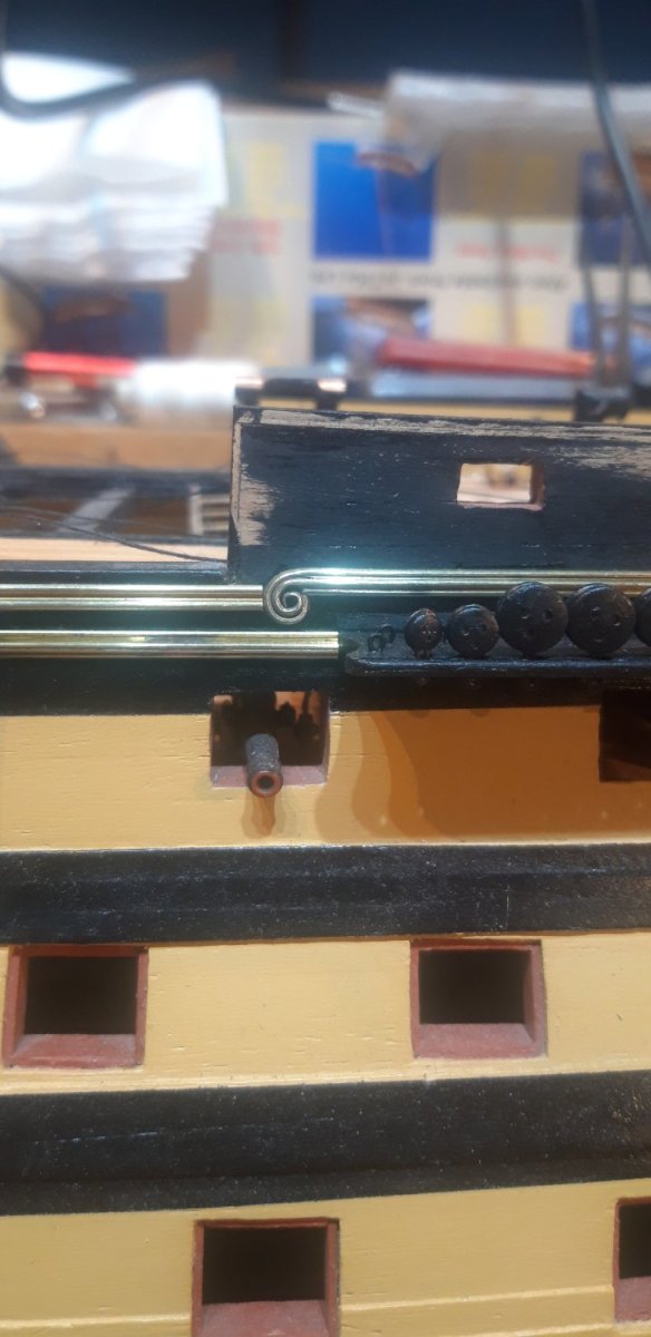
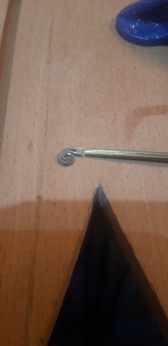
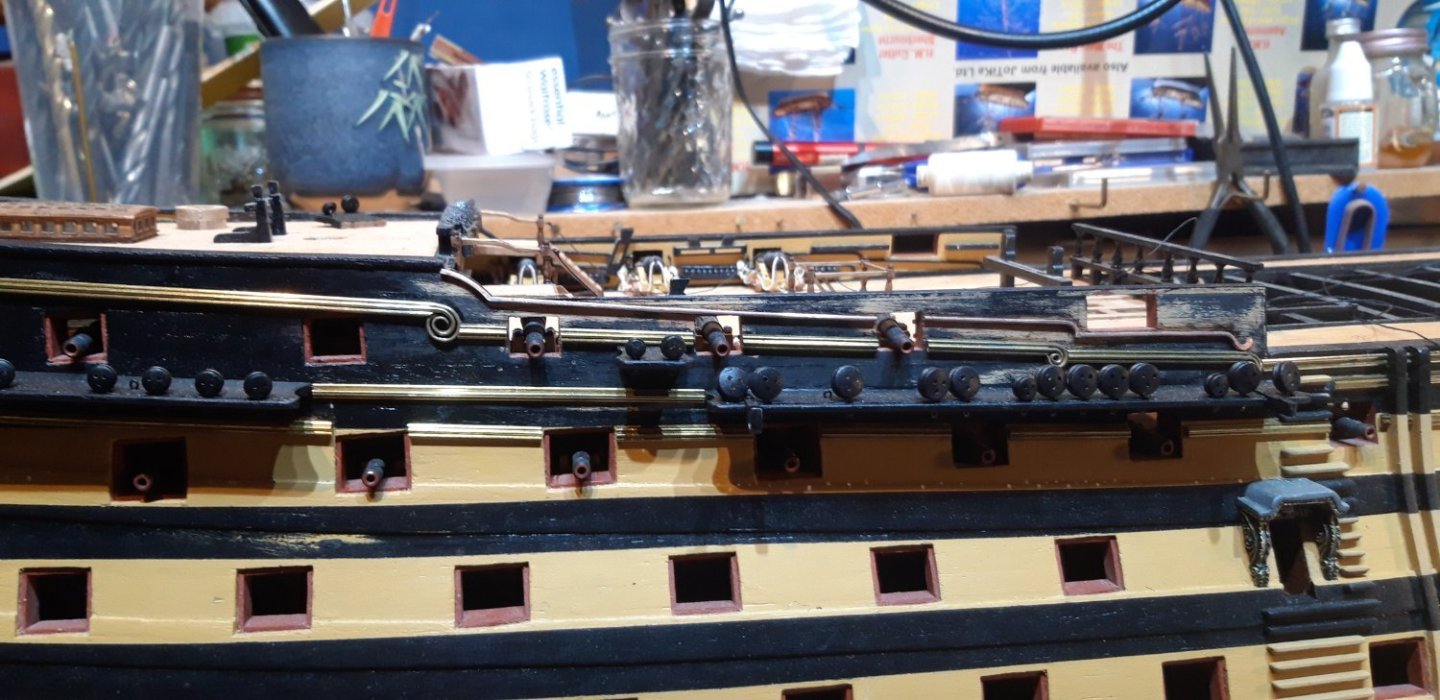
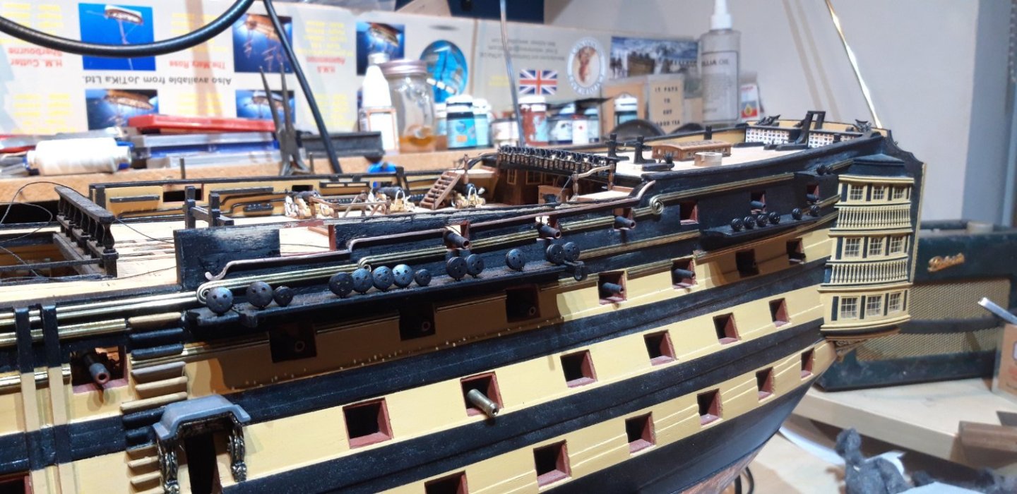
This picture shows my first attempt at the decorative scrolls, refered to as moulding swirls in the manual, that enhance the hull decorations. The method that the kit provides is a bit lacking and many builders have come up with alternative improvements. My plan was to try and replicate the way these scrolls flow from the straight sections of brass profile. This first attempt is very rough but in terms of developing the technique and proving the concept it taught me alot. The first step was to use a piercing saw fitted with a 0/4 blade to cut 20 mm up the brass strip following the two thinest sections The second cut then turned out to remove the bottom piece The two remaining pieces were carefully spread apart wide enough to allow a needle file to access the inner sufaces to smooth them off. 8 mm was then cut off the centre section and the outer sides filed to tapered points One lesson learned from the test piece was not to anneal the strip until all the cutting and filing was completed. Once these two 'fingers' were annealled round nosed pliers were used to roll the centre of the scroll The top section was then bent around the centre The excess length was cut off and this piece pushed into place These pictures shows the scrolls in place and includes the larger scroll at the stern. This one was made the same way, the only difference being those two saw cuts which were made 25 mm long, and the tightness of the scrolls. Having the channels still removable at this stage made adding these brass strips more manageable, I certainly wouldn't want to have had to work around them! A word of warning relating to the channels. Looking at plan sheet 5 there are vertical lines shown under the three main sections which turned out to be PE support brackets (Part 626). I've looked through the manual but cannot see any written reference to them. Glad I spotted this now before adding the chainplate assemblies. Just a few more sections of brass profile to add to this side, then I can tackle the port side of the hull. Cheers, Graham