Charter33
-
Posts
455 -
Joined
-
Last visited
Content Type
Profiles
Forums
Gallery
Events
Everything posted by Charter33
-
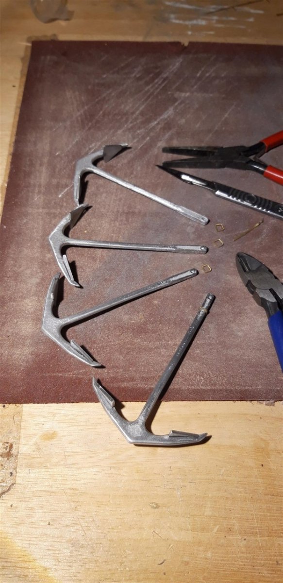
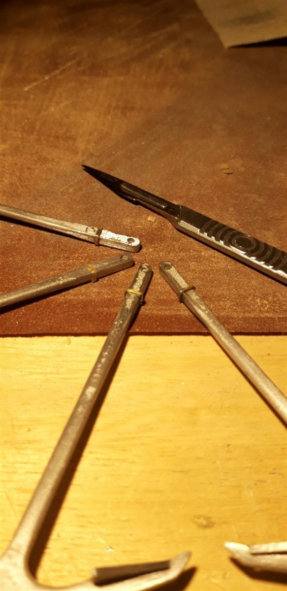
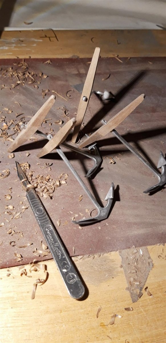
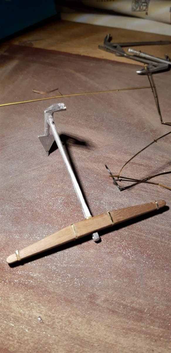
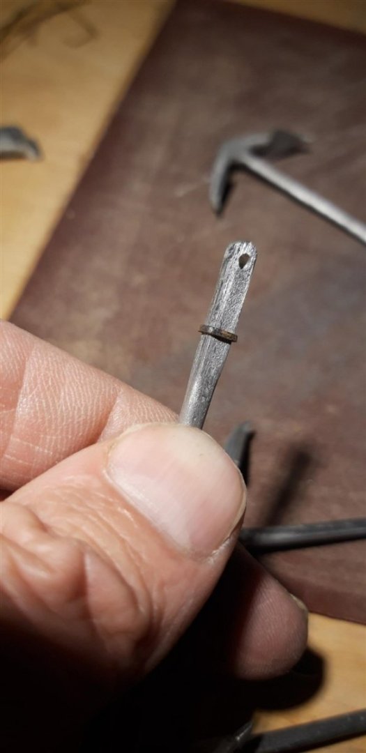
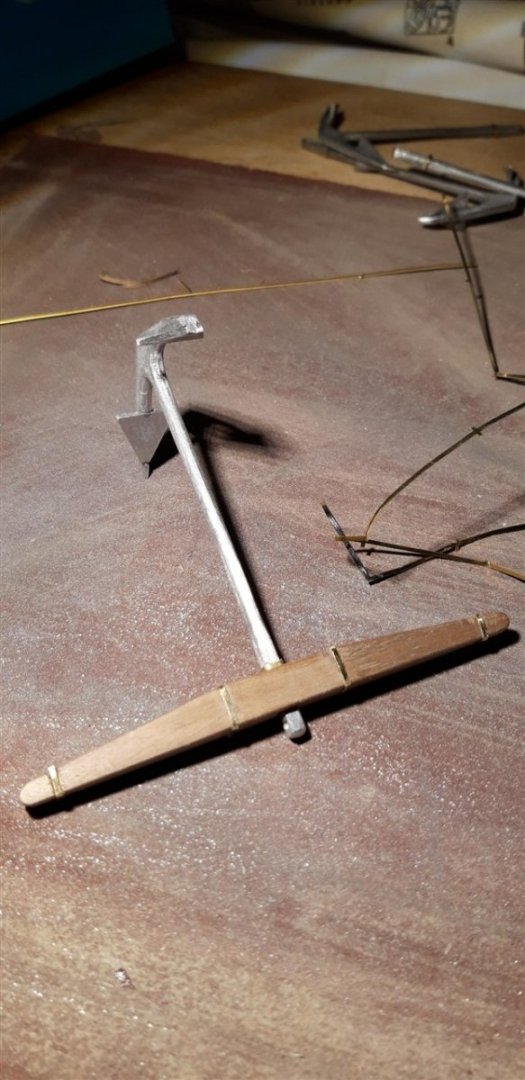
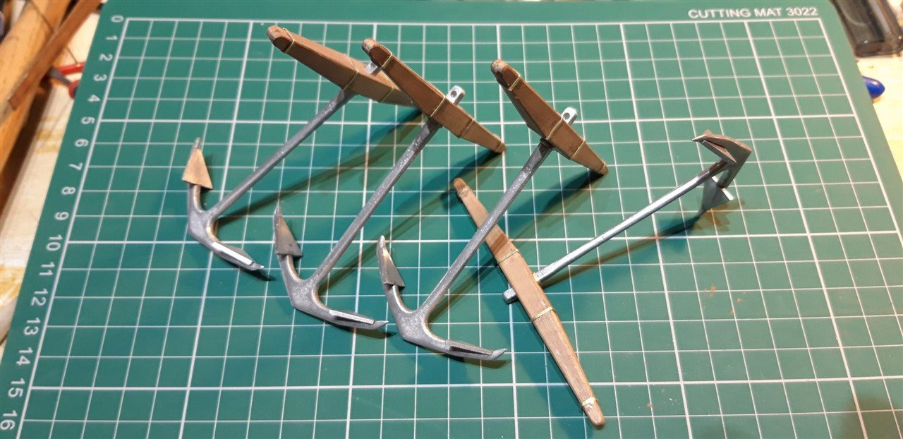
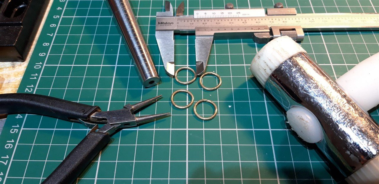
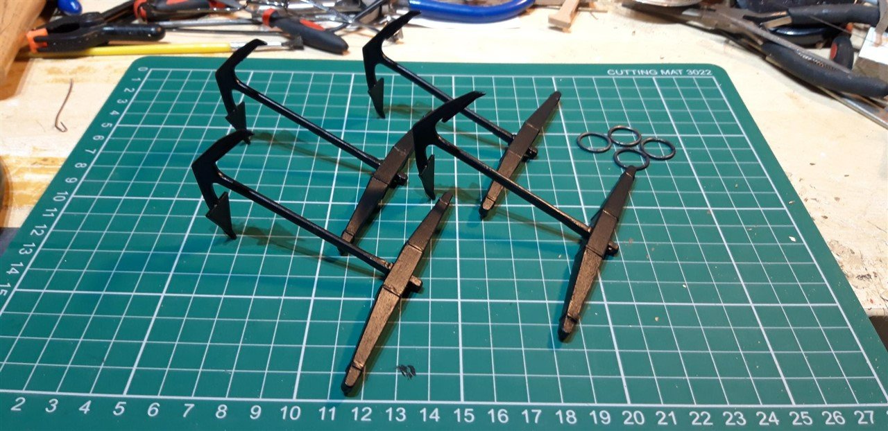
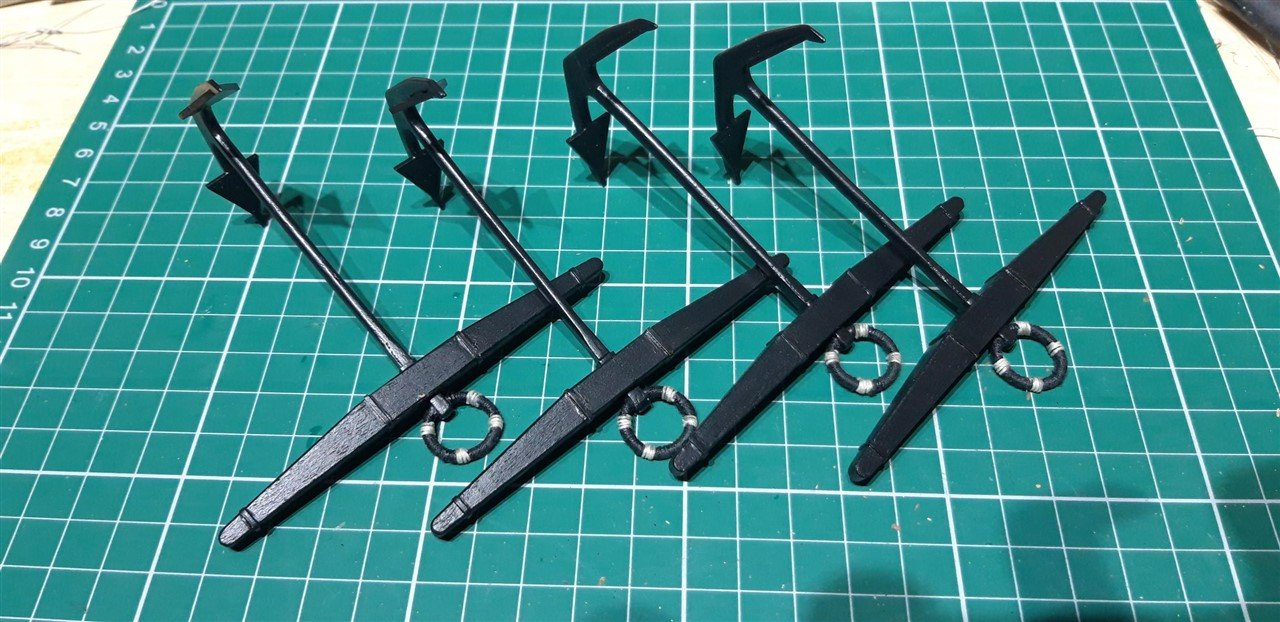
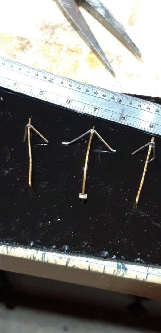
Construction of the anchors was well within the scope of the reduced 'building facilities' with my usual 'shipyard' temporarily little more than an A3 wooden drawing board on the dining room table illuminated by a clip-on flexible LED lamp. After cleaning up the castings and adding the anchor palms I made stops from some of the left-over photo-etched frame from the stern decorations, in this case from one of the thicker sheets. Once bent to shape they were soft soldered, cleaned up with a needle file and glued in place. Anchor stocks glued together and carved/sanded to achieve the tapers ...... ...... and after a light chamfer to the edges the iron bands were fitted, this time utilizing the fine brass strips recycled from the thinnest PE sheet frames. The rings were fabricated ..... and the anchors painted. After fitting the rings, darkened using 'brass black' solution, I looked on-line for advice on how to do the puddening. The search engine brought me straight back to MSW. Lesson learned - forget Google and just use this site's search tool! Cheers, Graham


-
Oh those Halcyon days - that picture takes me back ..... couldn't eat the contents quick enough....😅 Will be following your 'Pup' build with avid attention, Edward...
-
Hi Mike, and thank you. I just anneal profiles that need a significant degree of bending. A lot of the brass strips required are straight so are fine as supplied, just needing to be cut and finished to length. I put off doing the bow pieces that run from the Catsheads to the top bow rail until I'd had a bit of practise on the stern. These two need to curve through 90 degrees and also flow around the hull's curve. Should be fun! Cheers, Graham
-
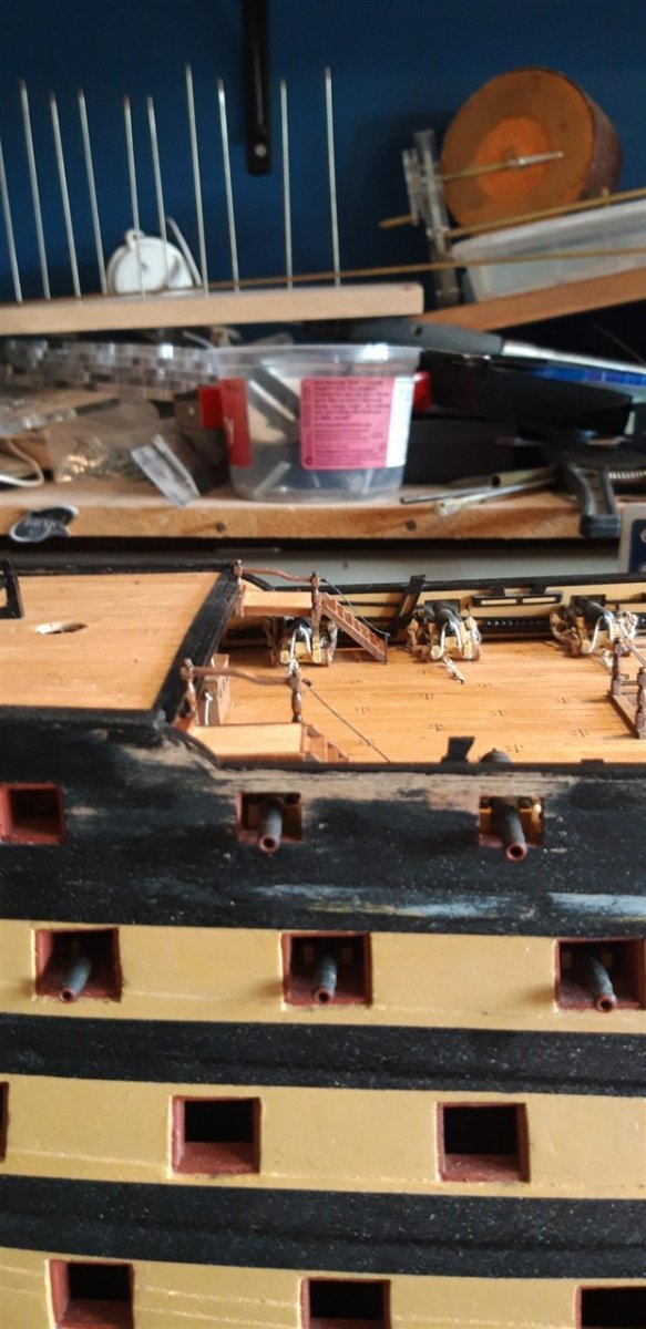
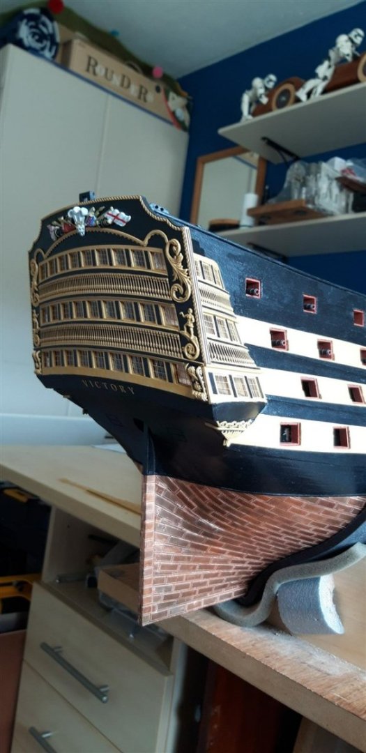
Well.... the brass profile decorations turned out to be more of a challenge than expected. It took a several evenings to achieve pieces that were of an acceptable standard and a couple of attempts that had to discarded, not just the compound curves but the bevelling of the ends to match the hull etc. Thankfully the manufacturer is generous in the amount of profile provided. Got there in the end and this stage of the stern is now just about completed. I'll attempt the two pieces to finish the the bow next. These look a little more tricky, but the brass profile is annealed and ready to go. Off to the West country for a break today so away from the shipyard for a little while - so 'anchors aweigh' ..... literally - the components for the bower and sheet anchors, plus basic range of tools, paints and brushes, oh, and the side entry port casting as well it seems, appear to have fallen into the bottom of the suitcase......... well, sometimes you need a mini project to keep you going ...... 😉

-
New workshop and tools setup.
Charter33 replied to John Murray's topic in Modeling tools and Workshop Equipment
With over 40 years of teaching Design Tech at Secondary level, plus running two Adult ed. courses a week for much of that time, I'd offer to drop by and show you ...... the distance is a bit of a problem unfortunately 😆 -
New workshop and tools setup.
Charter33 replied to John Murray's topic in Modeling tools and Workshop Equipment
That's a great range of kit you have there John - dead jealous! Looks like an amazing base for some pretty impressive future projects. Good luck..... -
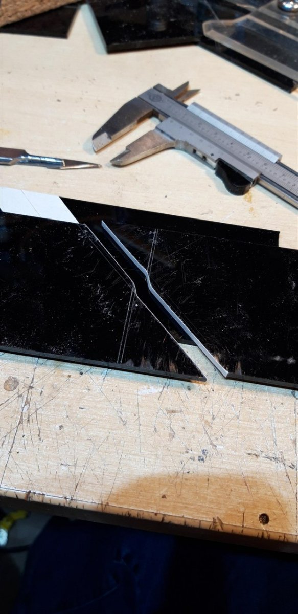
Hi Ron, When I had a parts problem I found that phoning Jotika directly was the best method of contact. That broken part you have looks like the lower curved rail for the bow. Once fixed in place it's not under any load and is supported all along the back. It also will need trimming in length to fit properly. You might find that it is still usable... Great progress with that second planking and squaring up the corners of those ports - keep up the great work!
-
Coming along very nicely!👍
-
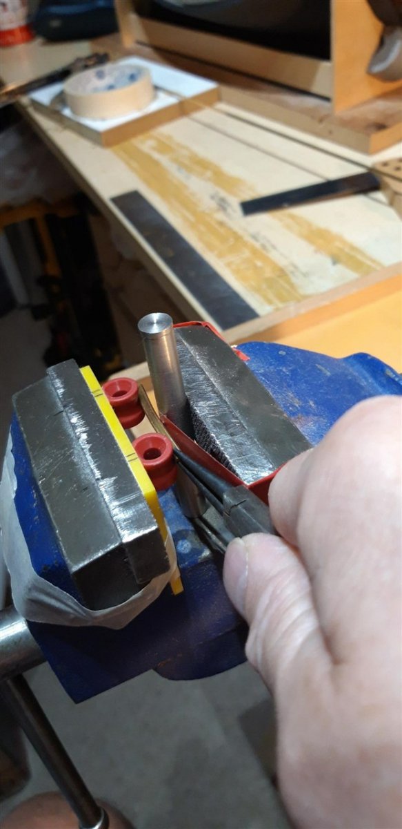
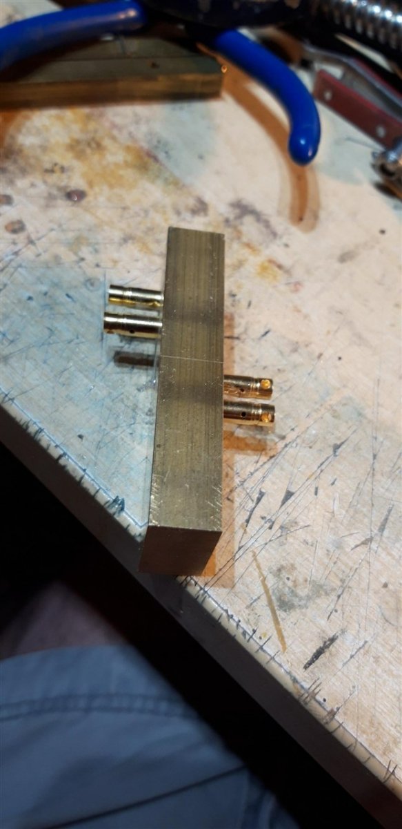
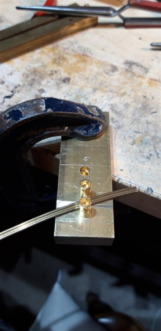
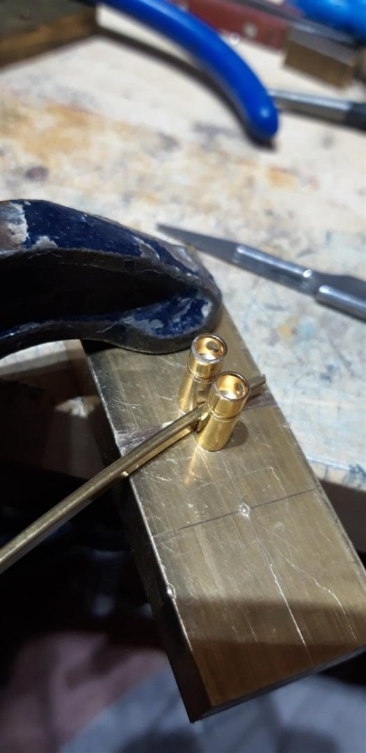
Well ....... turns out it's one of those instances where half a dozen lines of instructions in the manual proves to be deceptively vague and a bit more thought is needed ........ I managed to bend the brass profile to the correct shape to match the curve on the top part of the Quarter gallery but then found out that it was a compound bend and needed to also curve slightly upwards. Got a bit creative with some bits and pieces that were to hand and came up with this solution .... successful, but not very elegant..... There had to be a simpler way ...... time to go back to the drawing board. Rummaging through the 'odds and s*ds' box I came up with a random block of 'bound to be useful one day' brass and four 5 mm dia. brass connector pins. Four drilled holes and the light application of a hammer later I now have a double sided jig to to form the brass in both axis'. 2 mm gap between pins on one side, and 3mm on t'other. A long way still to go, but I'm a bit more confident that it's do-able...... Cheers, Graham


-
I'll join you down there, Andrew, for a pint of 'heavy' - it's been a stressful day....
-
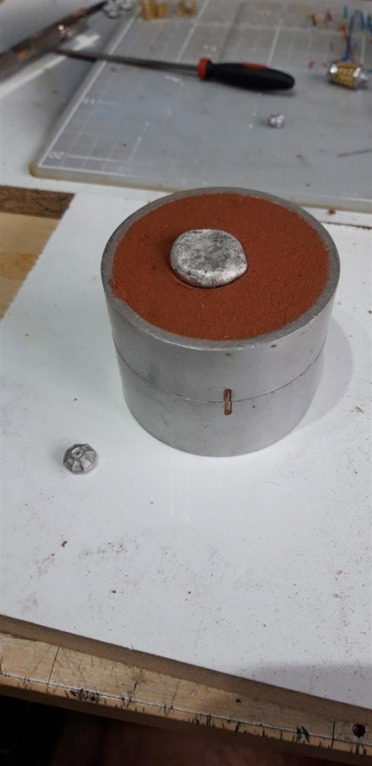
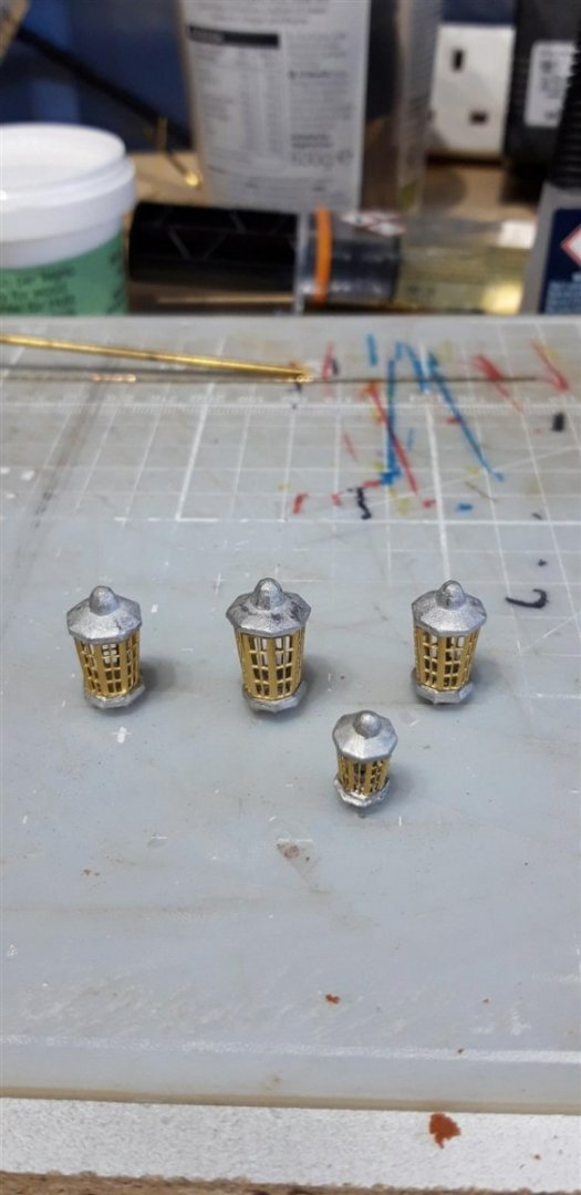
Thank you for all the positive responses, always a great motivator! Totally agree with you about the windows, Robert. I'm really pleased with how they came out. I also followed your example and added those two extra wooden mouldings under the false baluster pieces on the Quarter galleries using 1.5 mm pre-rounded strips cut from some unused first planking material. Another great suggestion - thanks again. Andrew - you're so right about the effect of adding extra detail. It not only improves the appearance, it also adds to the enjoyment of the build. Time well invested, as you showed with your superb 'Nisha' 👏 Working on the stern lamps I was tempted to add a new tag to this thread - 'misadventures in modelling' or 'a comedy of errors'........ Having successfully drilled three of the lamp base castings for their supporting frames, the 0.7 mm drill bit started to bind on the final one and before I could turn the Dremel off the casting had twisted out of the vice, bending the drill bit, and was projected across the room. I did see a couple of the rebounds it made off walls etc. before it finally disappeared into a parallel universe. Time spent looking for it proved unproductive. The only saving grace was that the lost base was from one of the two middle sized lamps and its twin could be used as a pattern. Having dug out the Delft clay and associated equipment the mould was created and some metal (pewter) melted and poured. Did it work? oh yes...... Not as crisp as the original, but serviceable after a little fettling...... Lamps assembled prior to gluing and painting, but first I fabricated the fames to support them based on images found on-line. Once painted it was time for a dry fit before removing them and adding them to the growing collection of parts being stored until closer to the end of the build for their own protection. Time to start work on shaping the brass profiles to finish the stern facia and Quarter galleries. Cheers, Graham


-
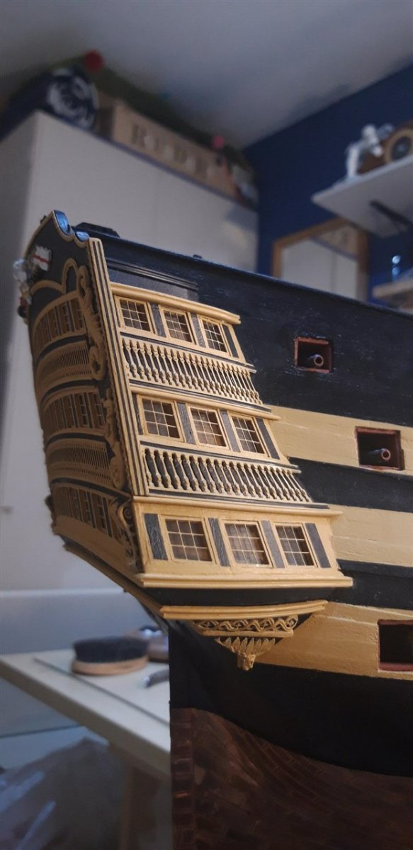
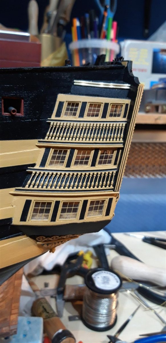
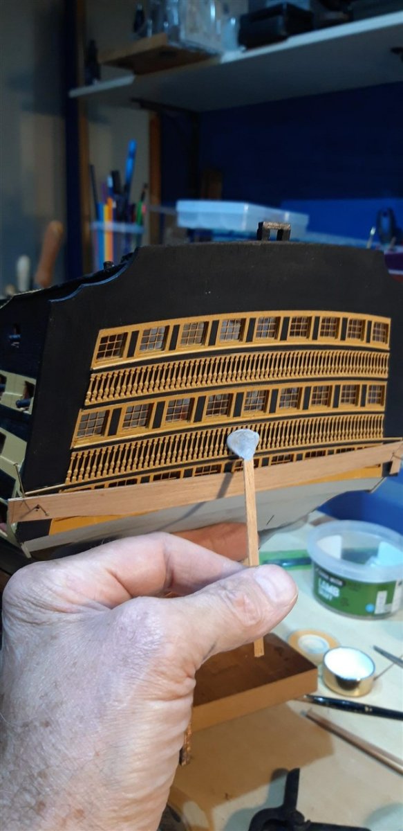
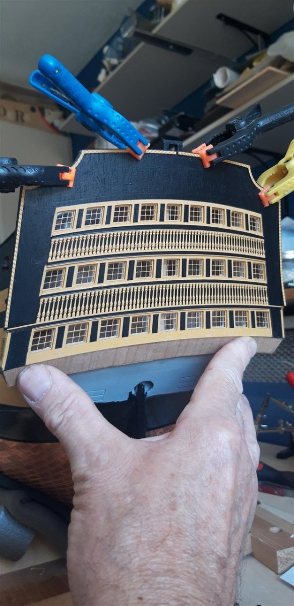
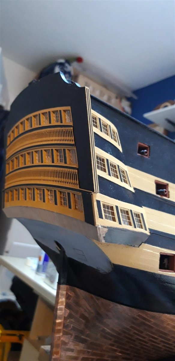
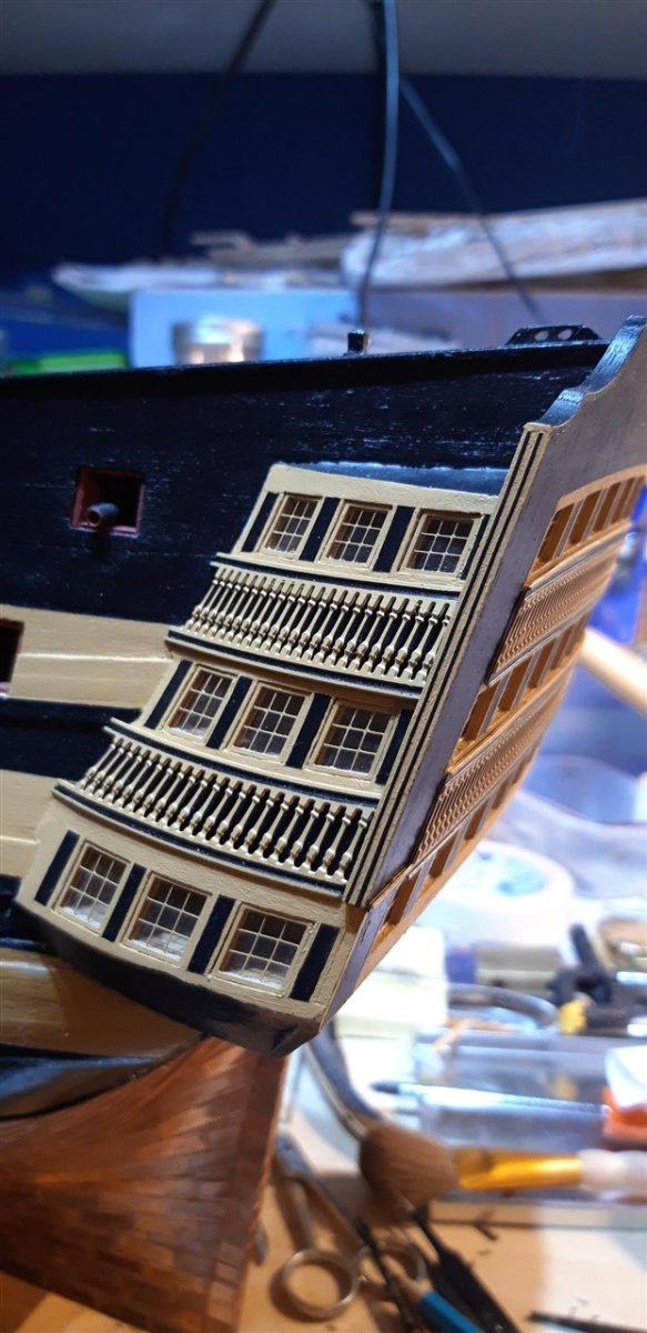
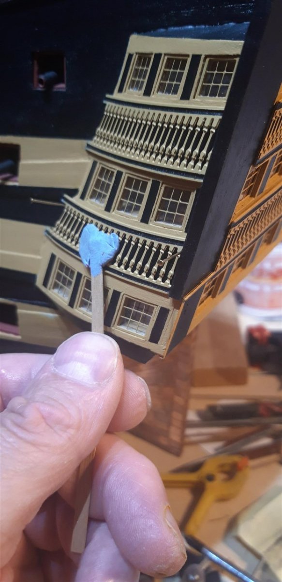
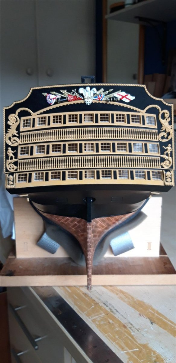
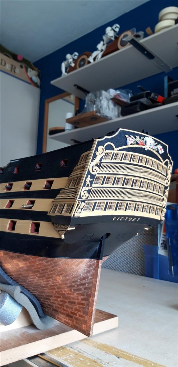
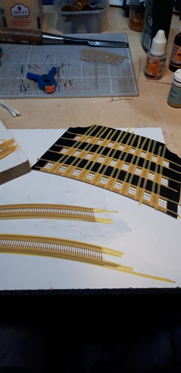
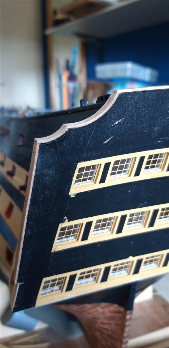
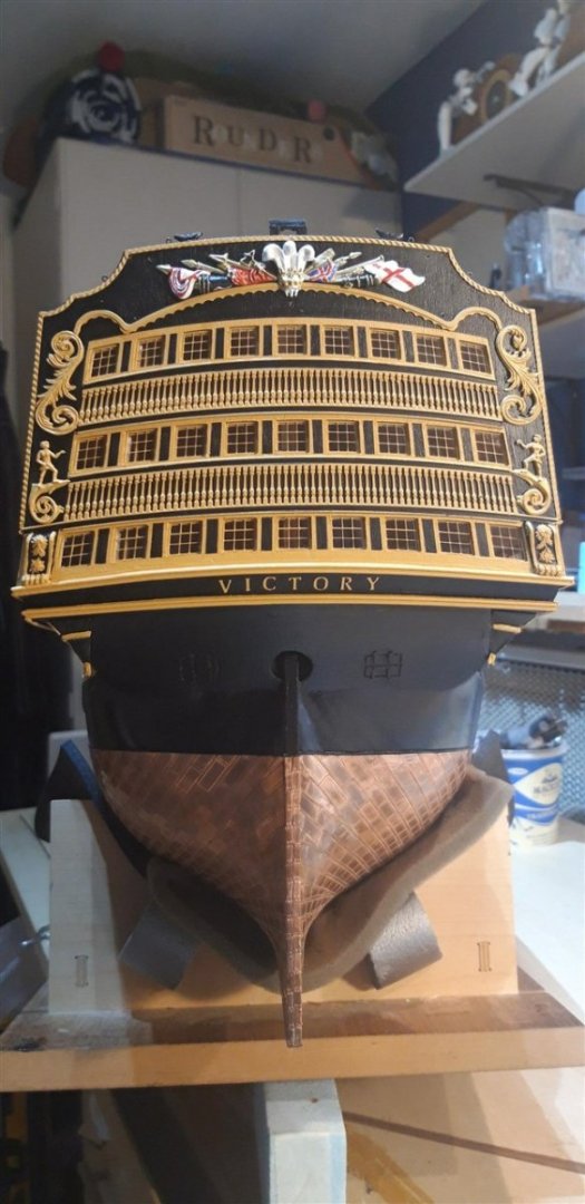
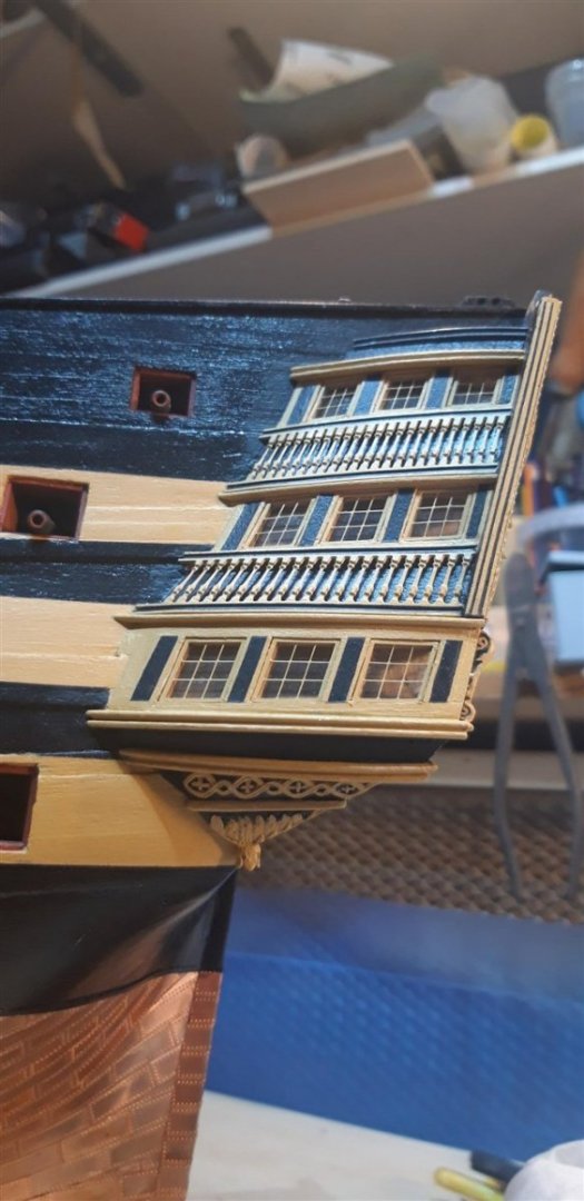
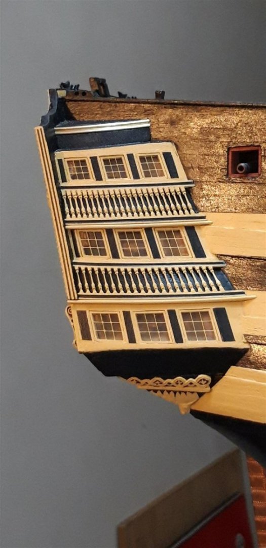
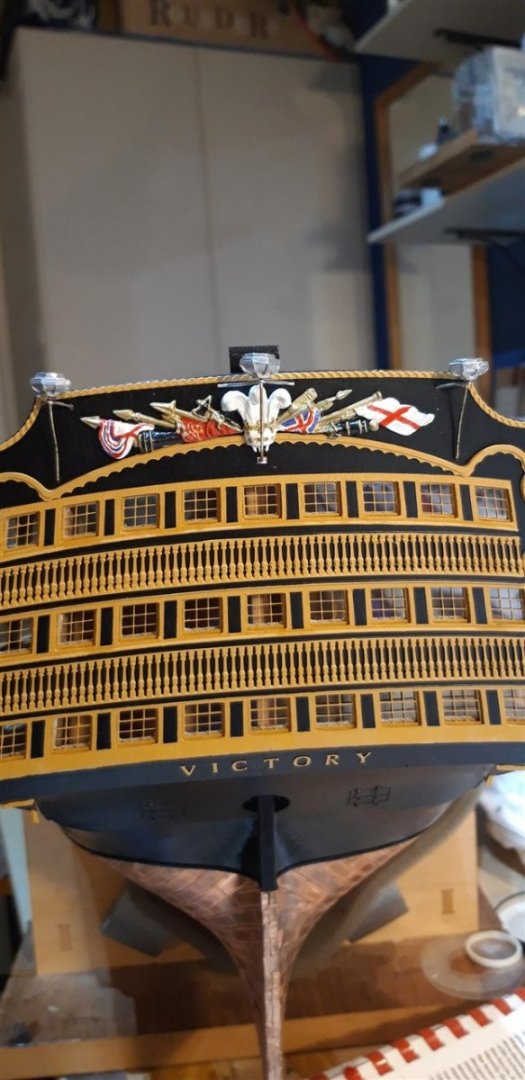
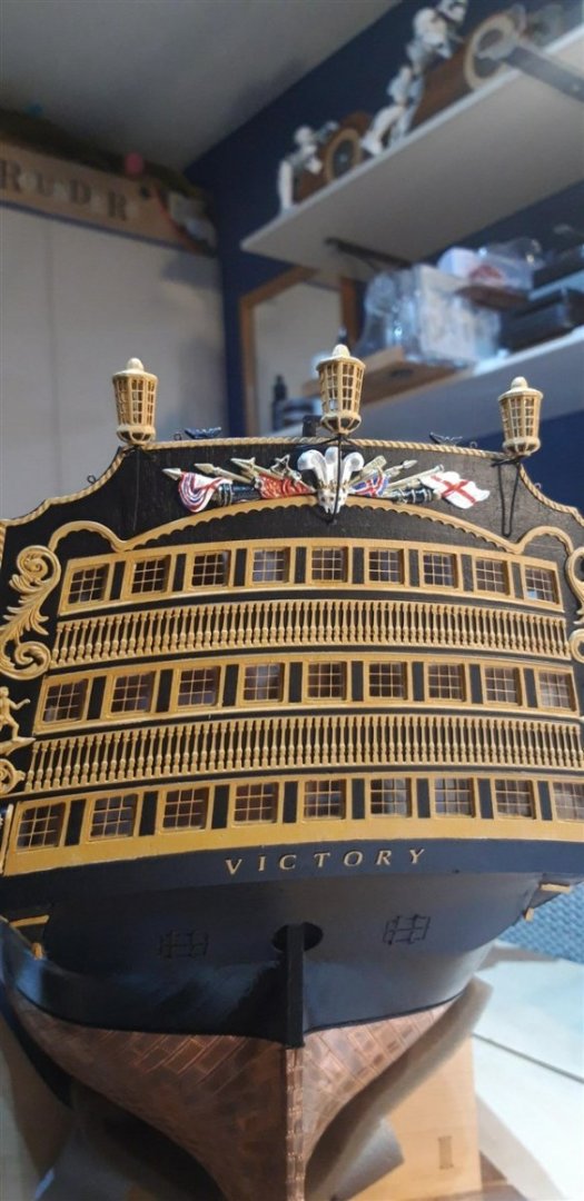
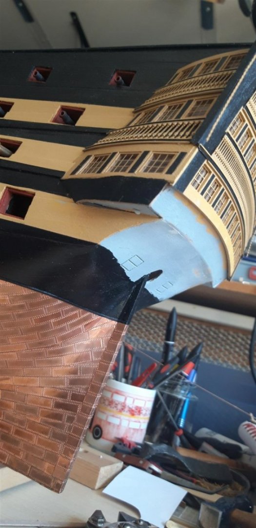
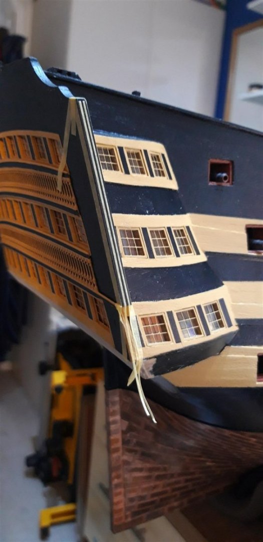
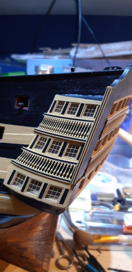
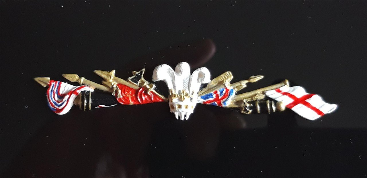
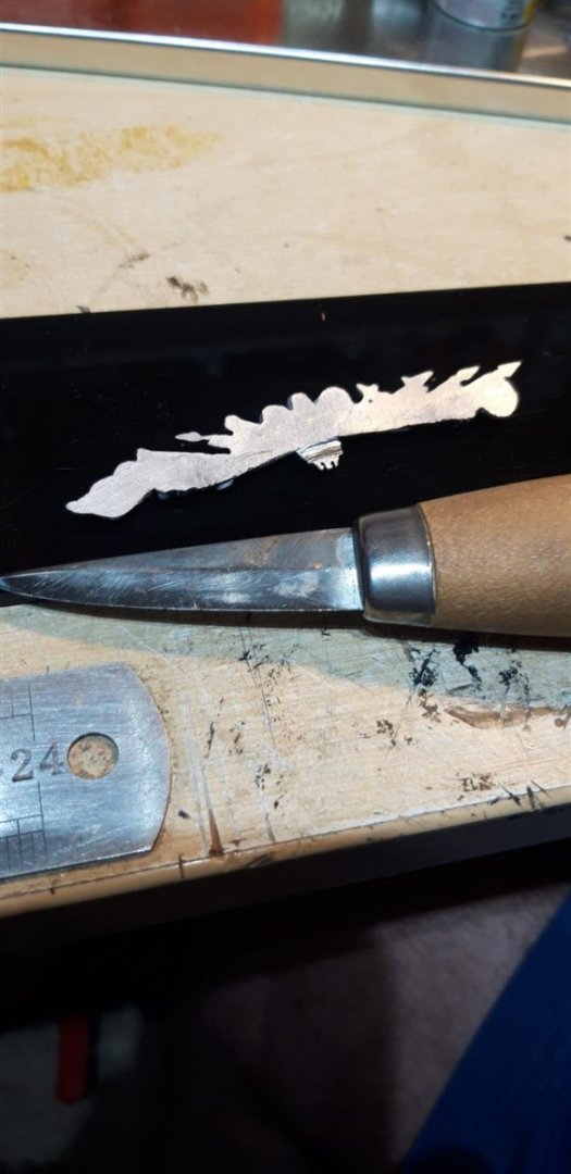
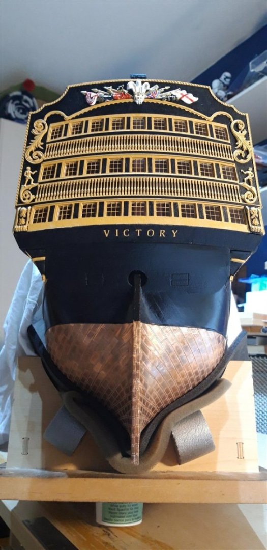
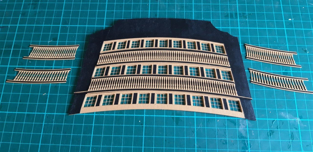
I've been focusing on the stern facia and quarter gallery decoration details. With the facia windows I have followed advice to mount the frames from the back of the outer stern facia to give the windows more depth. To achieve a similar effect on the Quarter Galleries I used Robert's innovation of adding an additional 0.5 mm layer to the three window skins. The two false baluster patterns were fixed with C.A. adhesive. With very limited time to align them I opted to temporarily pin a scrap strip across the facia to help. The simple 'tacky stick' gripped the pattern as it was placed in position. The gap between the facia's surface and the transom seemed a bit excessive, putting it mildly.... .... so I made an additional piece to improve things. I never throw away any off-cuts and found a piece of the 2 mm walnut ply big enough for the job. The hole in the remnant of the original transom ply made a perfect template. Edges bevelled as required ....... ...... and the new piece glued in place. The lower edge was then blended in with carving knife, file and sandpaper. To create the black panels between the Quarter gallery windows it was back to careful masking I wanted to add additional detail to the vertical edges of the facia so, after cutting strips of tape down to about 0.7 mm wide, these were put in place together with masking on the front and back surfaces, and the unmasked areas over painted yellow. To get the Quarter gallery false baluster patterns in place I used rapid epoxy to provide more adjustment time. Brass pins were pushed into the skins as an alignment aid. At this point I began work on the Trophy of Arms, carving the groove where it intersects the top stern facia moulding This was then primed together with the other white metal components - and all the associated tales of woe explained earlier in the 'What have you done in the garden today' thread 😖. Once painted yellow these castings were glued in place, once again using epoxy adhesive. ...the errant scroll was the one bottom left! The Trophy of Arms was painted up using images found on line. The left hand draped flag was re-worked a couple of times, and I'm still not completely happy with it. I'll probably go back to it in the future Ship's name added, A couple of daylight pictures with the drop decorations in place. and finally I made a start on the lanterns..... Cheers, Graham.


-
Magnificent work Robert. The detail you're achieving is truly inspirational.
-
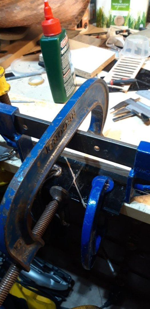
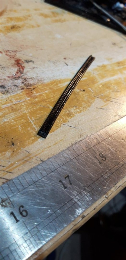
A beautiful, well executed and unusual project - thank you for taking me through it. I have a feeling that the black and brittle wood in post #6 is probably ebony... Graham
-
The secret lies in using a good quality filler, careful sanding, then you only need light coats of paint😀. Have you seen the treatment Robert did to the Quarter Galleries, Ron? Adding an extra layer of 0.5 mm thick strip around the windows makes a much better job of giving a slight recess to the frames when fitted. I've just finished this on my build - will be posting pictures soon. Keep up the good work! Graham.
-
That's a really impressive amount of detail on such a small model, as is the detail in the water base and diorama back drop. Fantastic work - well done!
-
Great news that you have managed to resolve the problem Alva -I'm really looking forward to following your progress with the junk...... and you definitely deserve a medal for your perseverance! Cheers, Graham.
-
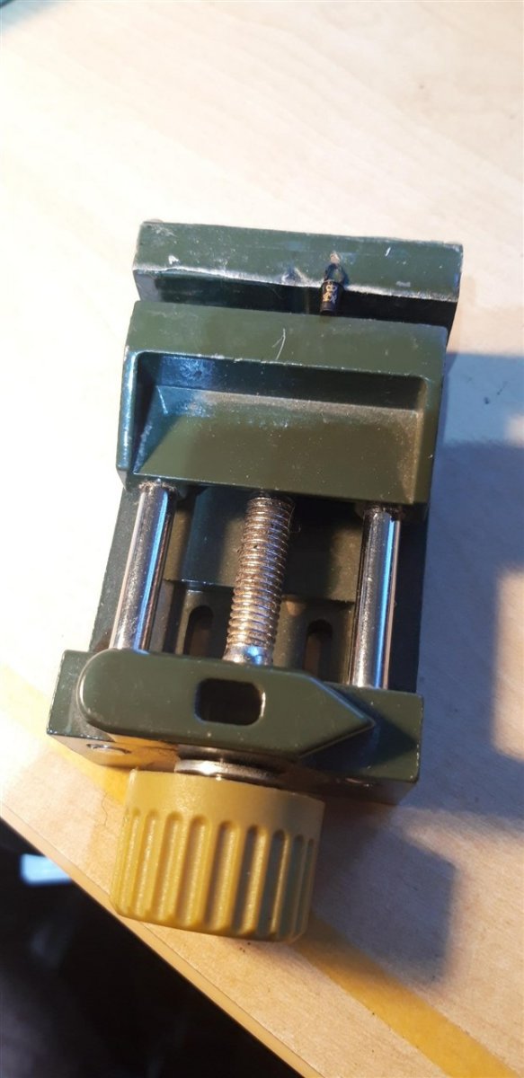
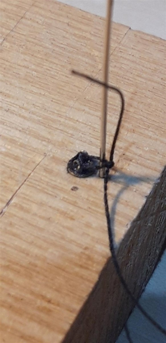
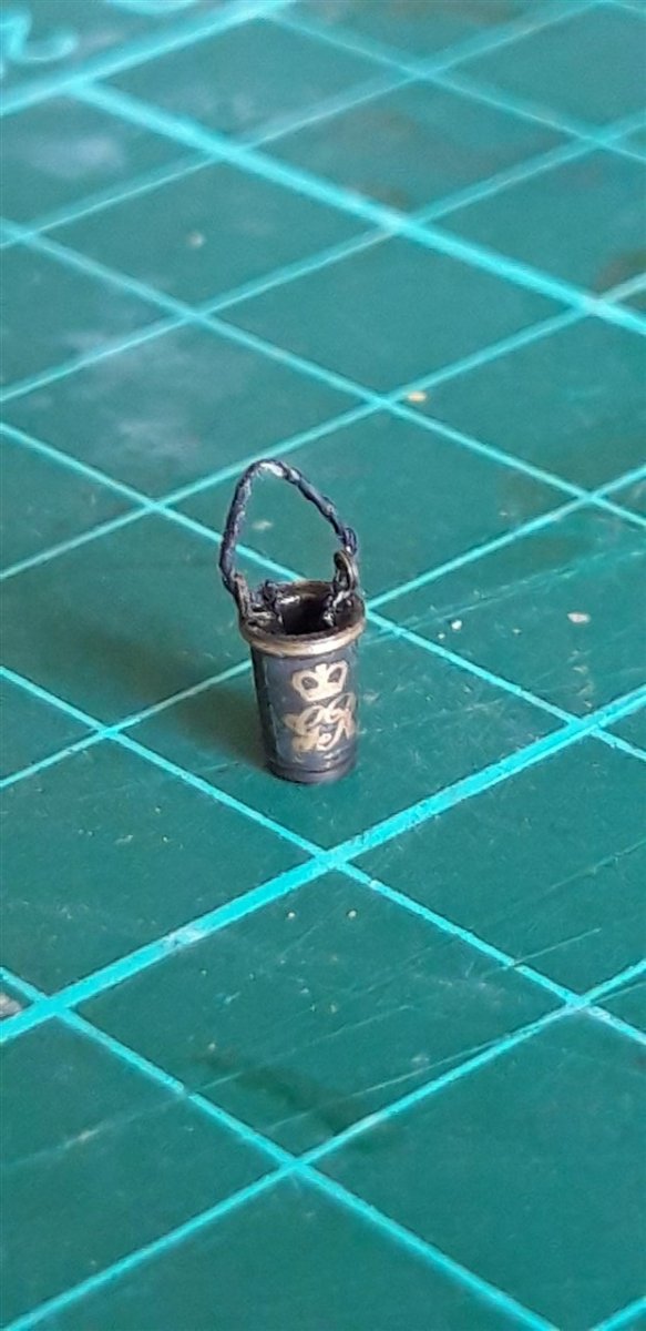
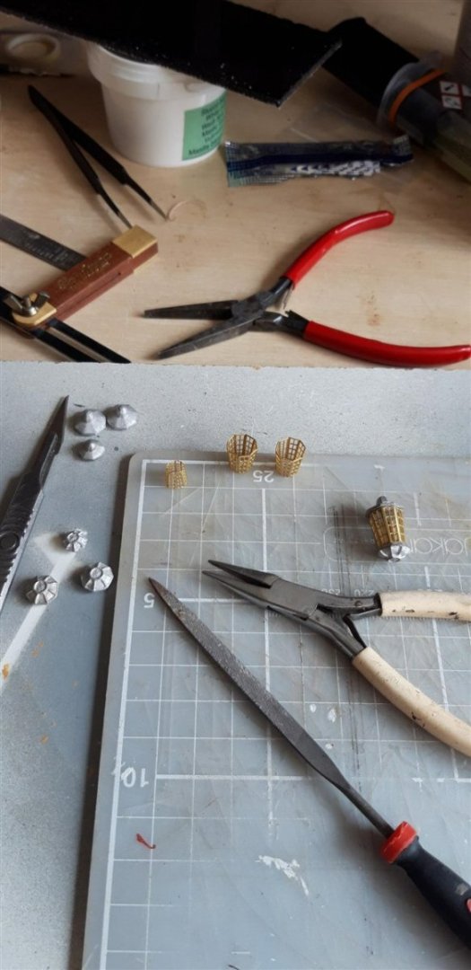
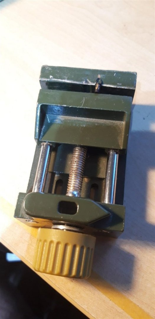
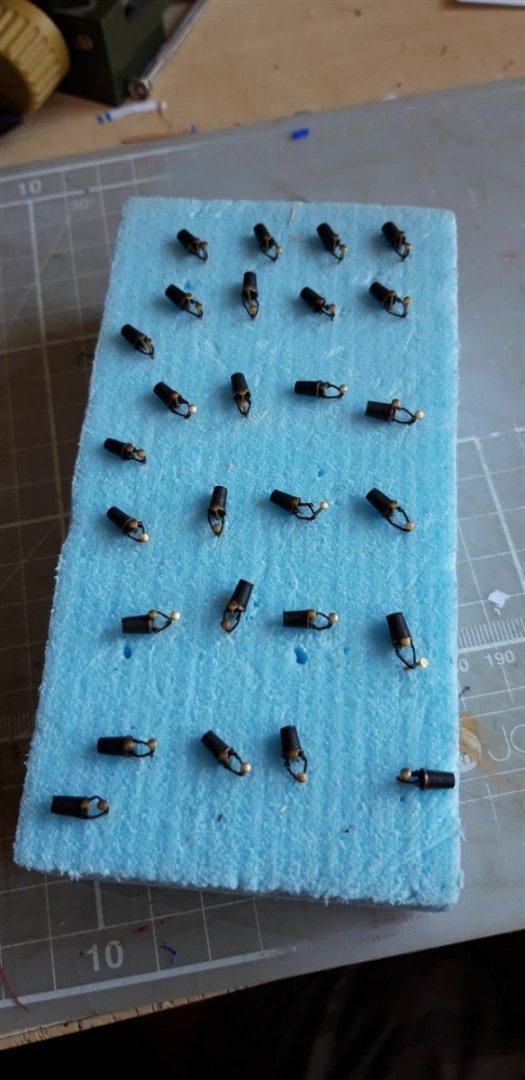
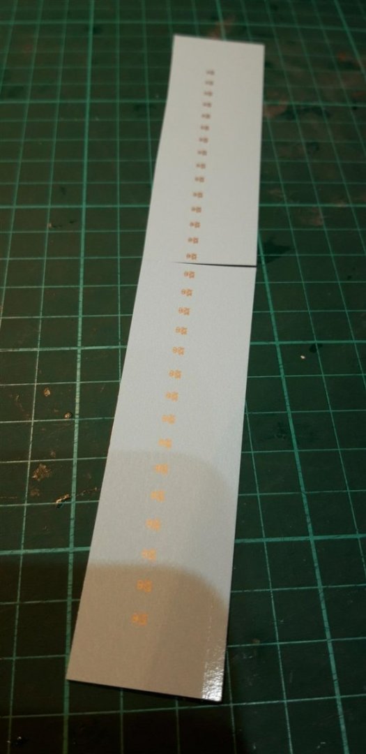
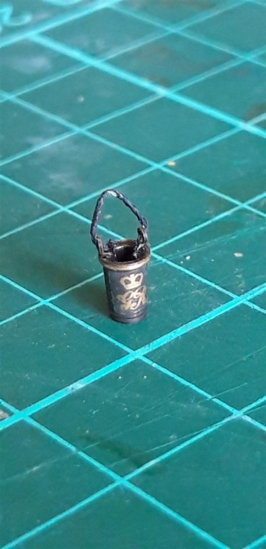
Those decals are fiddly little devils with minds of their own! I resorted to clamping each bucket in my Proxxon mini vice There's a strip of double sided tape across the fixed jaw to help set the front surface of the bucket on top, and yes, that tiny gold spot just about the handle is just one of the decals that got away 😒. I needed 21 decals, ordered 30 and have 4 left......... at 2.8 mm high and about 2 mm wide juggling the monogram into the correct position with a wet paint brush kept me gainfully employed for a long evening. I no longer have access to the CAD and CAM software and hardware I taught with unfortunately, so producing my own art work and using a good quality printer myself were no longer an option. (Never thought I'd miss the smell of freshly laser cut MDF, but I do....) Can't fault the product I received and the customer service was brilliant. A couple of pictures of that simple jig for making the bucket handles. A 4 mm hole for the bucket body, and a 0.5 mm hole, 5 mm from the bucket's centre, for a needle. Tying reef knots with two pairs of tweezers gets easier with practise, a skill that will no doubt become useful sometime in the future.😏 Cheers, Graham


-
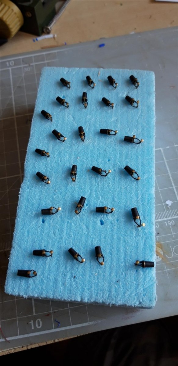
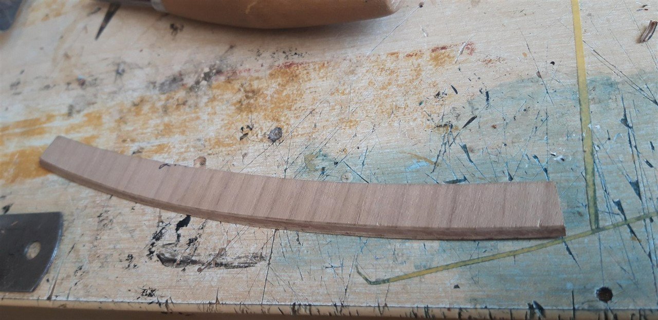
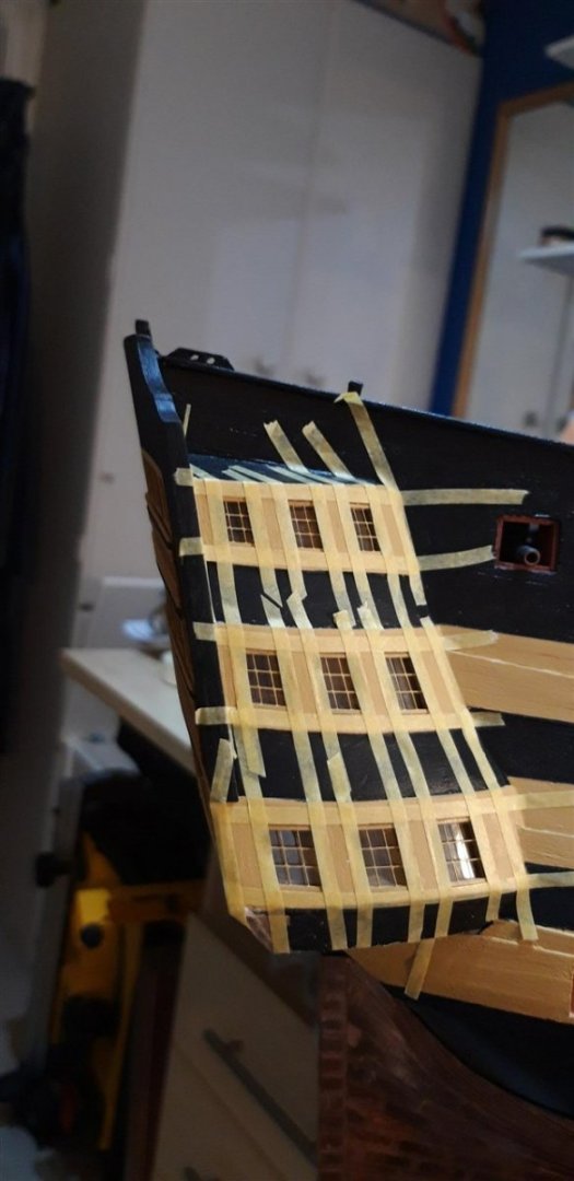
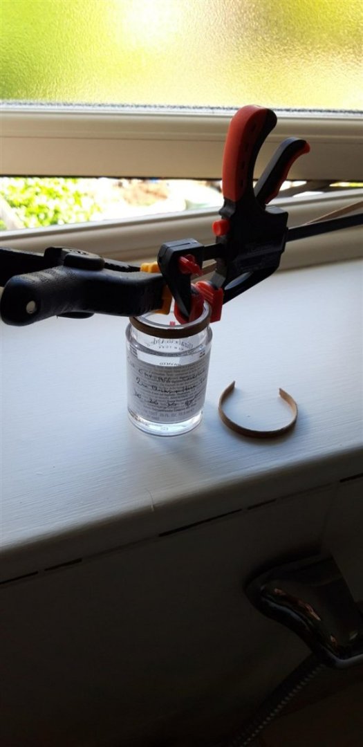
Thanks Andrew - and 2005 was the year that I embarked on this build too Mort. 😁 A slight delay in progress. Before tackling the stern facia I decided that it was time to re-organise the work area as it was getting a bit too cluttered. Space is a little tight, in fact I managed to knock off the starboard cathead when turning the model to access the other side one evening. Heard something snap, couldn't see any obvious damage so ignored it. Next day, with that awful sinking feeling, I spotted the problem. Couldn't see the assembly anywhere. The carpet has consumed many tiny components in the past, but a whole cathead? Eventually found it. It had pinged down the back of the workbench and then bounced under a set of draws - panic over...... and easily re-fitted. Then the pandemic finally caught up with me, fairly mild fortunately, but it still knocked me for six. All good now. When I trial fitted the fire buckets a couple of posts ago it was clear that there was an issue with the copper wire handles I had given them. They were too short and it was difficult to get the buckets to hang correctly. Only solution was to remove these handles and replace them with the recommended black .25 mm thread. Not easy.... First attempts with the thread tied to each eyelet was disappointing with the knots looking a bit 'tufty'. Solution was to tie the thread in a complete loop, a simple jig to ensure consistent size, and the knot in the loop being pushed down into the bucket to hide it. Buckets were then pinned to a piece of foam to pre-shape the handles which were given a light coat of matt lacquer to set them. Next job was to source the GR and crown monogram decals to enhance the buckets. With international postage rates so high I wanted to find a UK based supplier. On the advice of a good friend, a dedicated and highly accomplished model railway enthusiast, I contacted John Peck who operates the on-line company www.precisionlabels.com His usual range of products is railway based but he also does 'custom' work. Working from an image I found and sent him he produced the artwork and came up with these little beauties in just under a week, and at a great price too..... First bucket... Brilliant! A light coat of Decalfix made the clear carrier layer less obvious. All buckets now in place. Time to start the stern facia. After an initial painting of the black and yellow areas the window frames were fitted. To create the black panels between the windows I used Tamiya masking tape. At the same time I masked the P E baluster pieces, after painting them yellow, in preparation for the black lines. Preparing these with the VMS metal prep certainly improved the adhesion of the paint to the brass - thanks Robert! P E panels laid in place but not yet glued.... Once the facia was fitted it was time to add the capping. The instructions say to use 3 x 1 walnut strip, but this seemed too narrow. Instead I went for 4 x 1, and glued two lengths of this together to get a piece wide enough for the top piece which curved more than I could get the strip to bend sideways to match. This double width piece was cut to the required shape with a scalpel and sanded to final shape after gluing in place. To bend the curved sections on the top corners strip was soaked for 5 minutes in boiling water and then clamped to a suitable former, in this instance an acrylic cosmetic jar donated by the admiral as a storage container for small ship components..... Left to dry overnight the resulting shaped wood was cut to length and glued in place. Last picture shows the capping after it's first coat of paint. Added some more detail to the flag locker - signal flags made from the backing sheet from self adhesive labels, coloured with alcohol based permanent marker pens and folded to fit. Time to start preparing the stern decorations..... Cheers, Graham.


-
Looking good - I found these one of the more challenging stages of the build, just didn't seem to have enough hands....🤔
-
Just a thought - how about using layers of micro ply? Available in thicknesses from less than 1 mm, up to a couple of mm, strips could be cut, glued to achieve the required final thickness and clamped to the bulkheads to form a laminated curve, and no need to make those shallow cuts...
-
I'm hoping that this is the right place for this comment, and I have no idea who is responsible, but to whoever came up with the idea of including thumb nail pictures as part of the display that shows new site content - brilliant idea! Thank you......
-
- 7
-

-
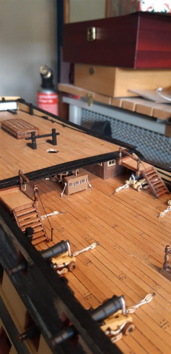
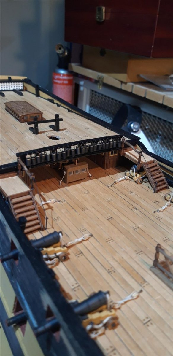
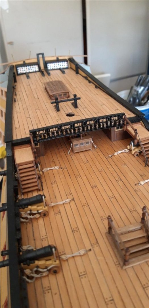
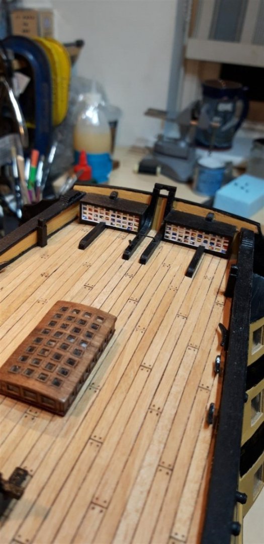
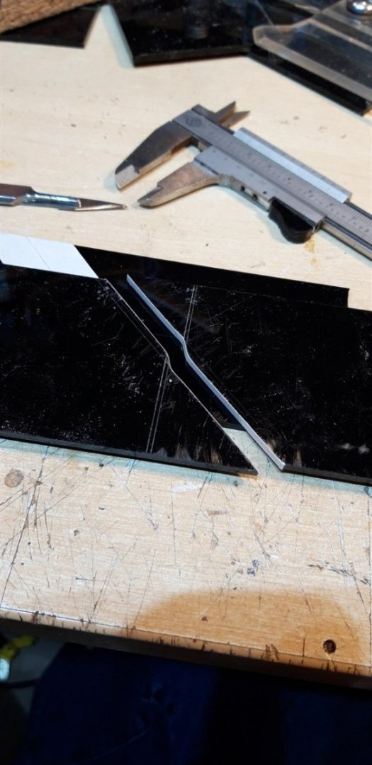
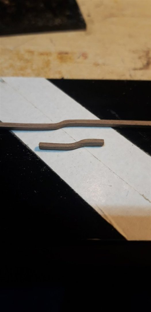
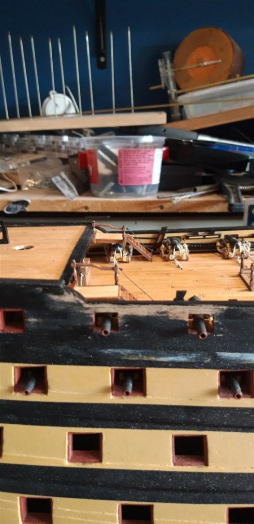
More progress...... Mort - good to know it wasn't just me! I couldn't work out if maybe I'd done something wrong. Possibly it was an issue with earlier kits that has been subsequently resolved (my build has been underway for quite some time!) Going back to the flag locker, I found that there were some different versions of how many sections were blanked off adjacent to the outer transom knees. I changed these from the photographic evidence of a contemporary version, four sections, that I originally included, to that shown in Longbridge's book - just two on the bottom row. Moving on to the Poop ladder assembly I decided to try to improve the handrail. Rather than fabricating it from 1.5 mm sq. walnut I hoped to be able to achieve the elegant curves in a different way. Option one was to try and steam bend the stock material. It seemed unlikely that this would work so I went for an alternative method that involved laminating the profile using three lengths of 3 x 0.5 mm walnut strip. The press forming tool was made from a piece of acrylic - the forming surfaces lined with double sided Sellotape with one side retaining the protective (PTFE coated?) cover to reduce the chance of the component sticking to them. This is probably one of the most 'Heath Robinson' forming solutions on this site!......... but it worked...... After a light sanding and trimming they were attached to the rest of the assembly which went as described in the instructions. These pictures also show the fitted poop deck termination rail. As commented on by other builders this part seems very plain compared to the the original. Using some of the copper profiles left over from additional enhancements I made to the quarterdeck plus some pieces of soft solder I tried to remedy this - Additional bullnose mouldings made from the 1.5 mm sq. walnut were also added to the top step. With the barricade assembly attached I did a trial fitting of the fire buckets.... There will need to be a bit of fine tuning to the handles to get them to hang properly before gluing in place, but I also want to add the GR emblem to each one first, just need to work out how........ The stern facia is next, but first I need to buy some more Dull Black paint as I'm almost out of it, and I have taken Robert's advice concerning VMS metal prep fluid, solvents and flexy ca for all that PE brass. CMB and Scale Model Shop deliveries expected shortly...... Happy days... Graham


-
Happy to help out - mistakes are there to be learned from, and it's even better when it's someone else's error! I'm in Bracknell, about 12 miles from Reading. Lived here for 60 years. My eldest son and his wife now live in the west of Reading in the Tilehurst area. Cheers, Graham
-
Hi Martin, Yes - definitely trim off the excess! I made the mistake of not doing so, assuming that because the lateral alignment was fine all was okay. Wrong! Overcame the problem but it wasn't easy, as you will see in my build log, posts #15 and #16. Good luck... Graham