Charter33
-
Posts
455 -
Joined
-
Last visited
Content Type
Profiles
Forums
Gallery
Events
Everything posted by Charter33
-
Hi Robert, and welcome to MSW from another Thames Valley based member. You've come to the right place for advice and plenty of others will chip in with their thoughts. You can use the search function on here to research this model too. You'll find an excellent kit review by esteemed member James H. Good luck with your project. Starting a build log is a great way to get advice, feedback and support! Cheers, Graham
-
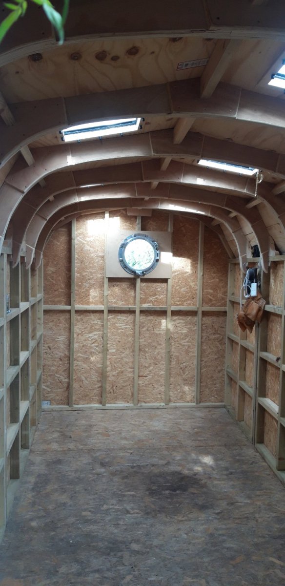
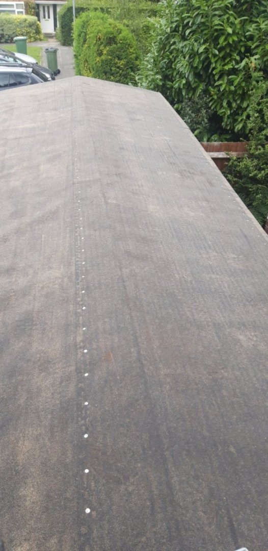
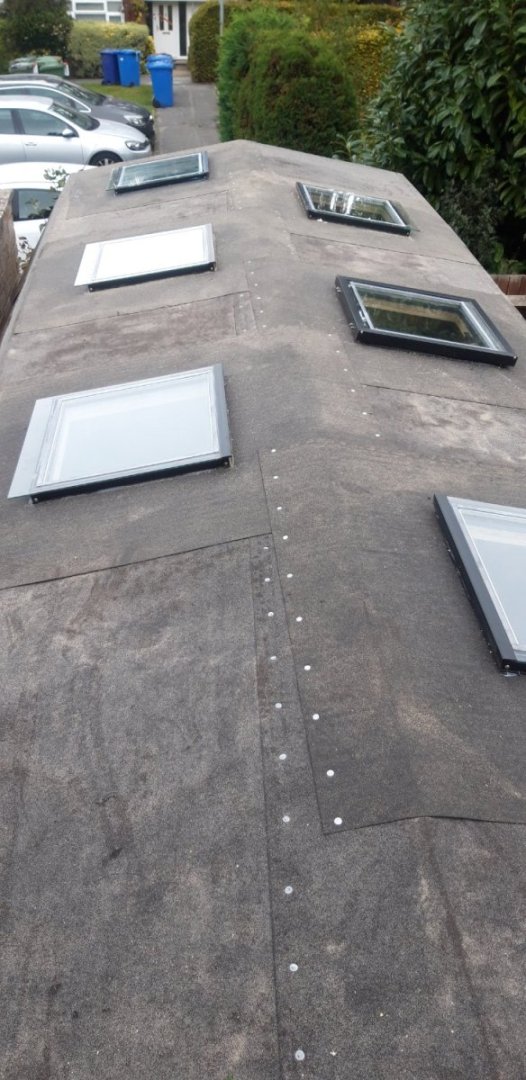
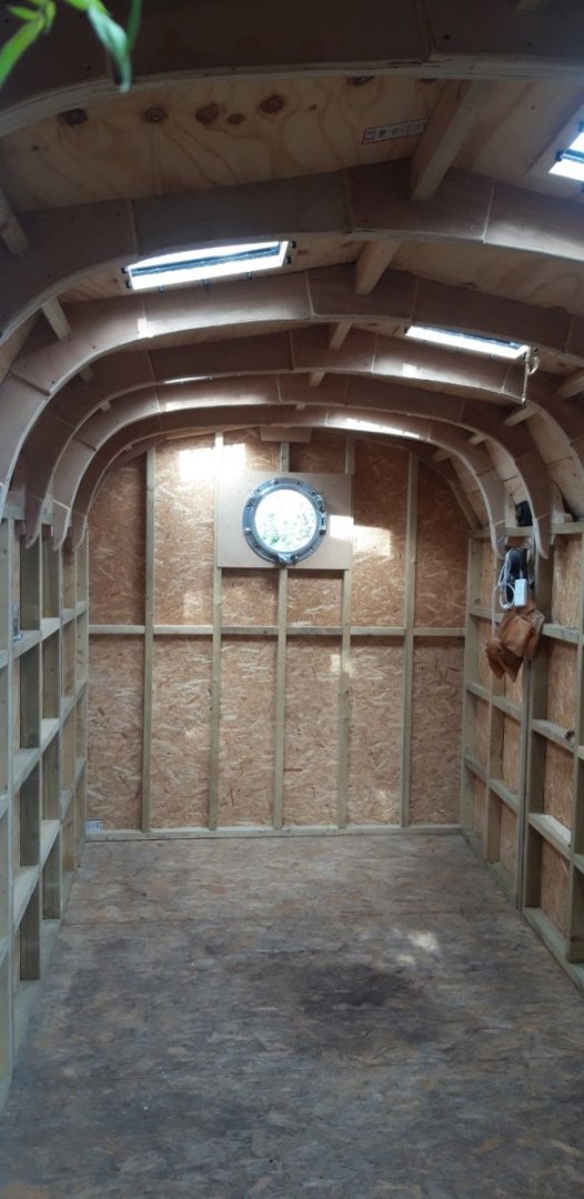
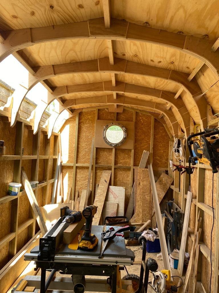
Having achieved a water-tight roof covering it's time to start cutting holes through it! Took the best part of the day, but the six roof lights are now in place.... Here are a couple of 'before' pictures..... The camera has compensated in the second image and lightened it. In reality it was as dark as the previous picture. And 'after'..... All units are double glazed with the right-hand middle one opening for additional ventilation. Time now to complete the roof by adding the bitumen shingles. Progress 🙂

- 89 replies
-
- 19
-

-

-
Replacement for 2.6x16mm screw
Charter33 replied to DMM's topic in Modeling tools and Workshop Equipment
......contacting the kit's manufacturer is another option of course..... Cheers, Graham -
Replacement for 2.6x16mm screw
Charter33 replied to DMM's topic in Modeling tools and Workshop Equipment
Hi, Not sure where you're based but in the UK there's a company called accu.co.uk who list this size screw in a variety of finishes and head types. A quick search online could be a good place to start. Good luck! -
An absolute masterclass Robert...... Congratulations on completing your truly inspirational model.
- 527 replies
-
- 3
-
-
-
- caldercraft
- victory
- (and 1 more)
-
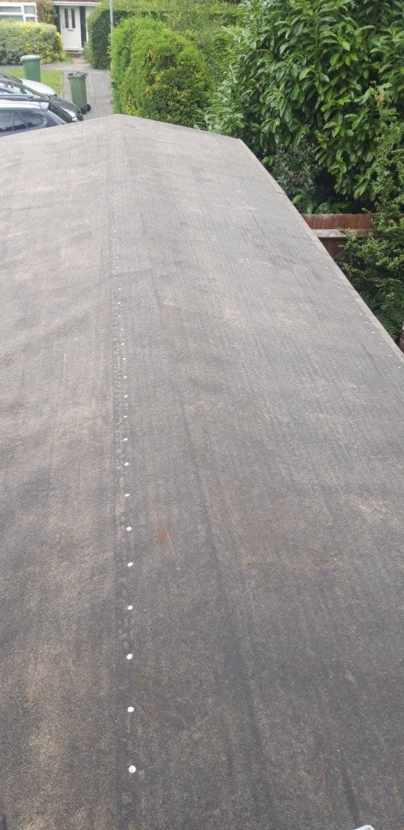
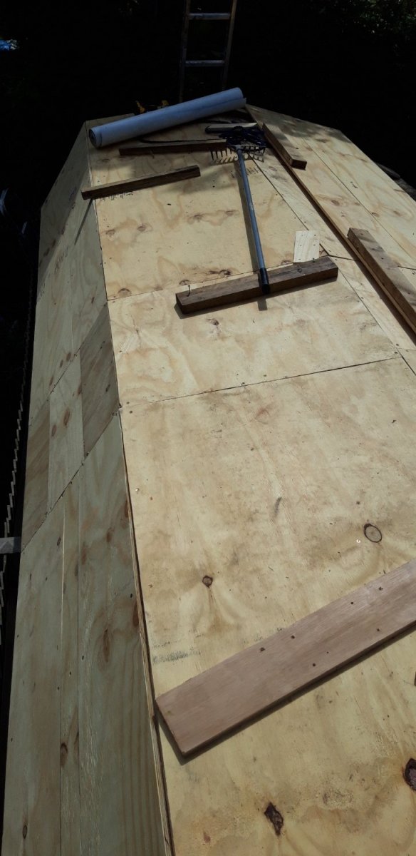
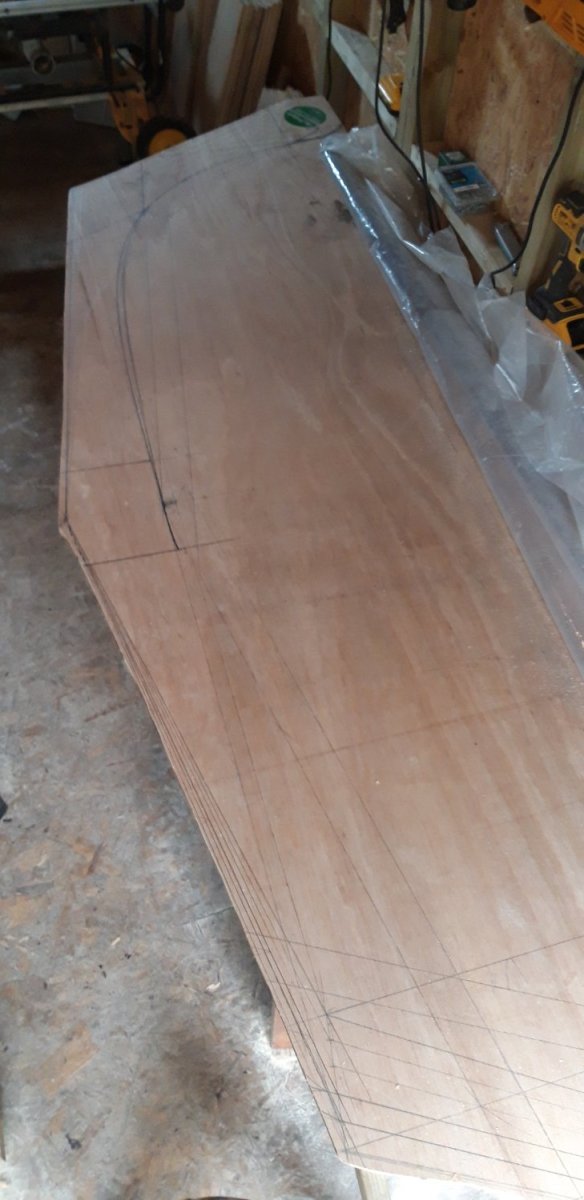
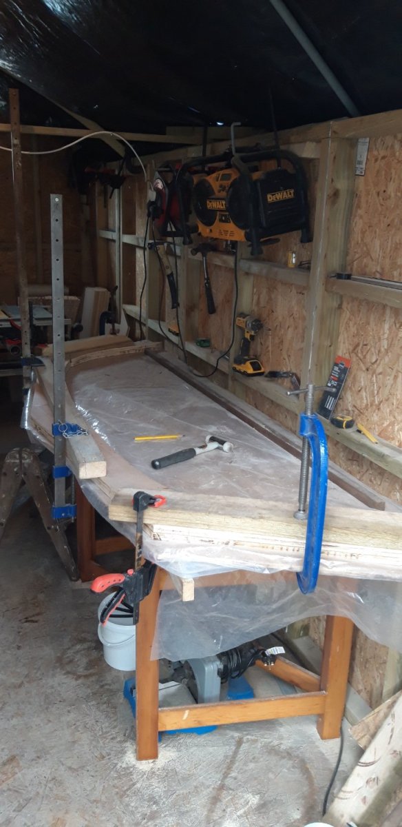
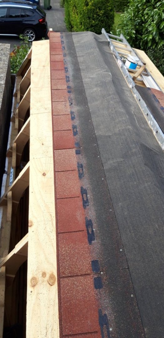
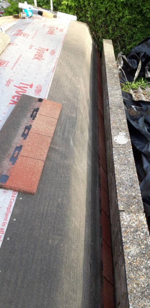
At last the weather has changed and the forcast is for a several consecutive dry days. I can finally remove the tarpaulin and polythene sheets, which have often appeared more like sagging water balloons recently, and work on making the roof waterproof. I reversed my original plan and worked on the more straightforward sections first before attempting the more challenging one adjacent to the garage wall. A bit of advanced planning to find the optimum way to cut the six 8' x 4' 18mm to minimize waste resulted in less than half a square metre of ofcuts. Not pretty but it does the job. Now for the fun part.... Relying heavily on the three 'Ls', leverage, lateral thinking and luck, the the final panel was constructed on the roof and dropped into place. I took steps to ensure the whole assembly couldn't fall down the narrow gap between garage and workshop wall. At about 16' long and a couple of feet wide it was quite weighty! After marking the end profiles it was pulled back out and trimmed ready for covering. First a layer of breathable membrane, then one of bitumen felt underlay. Next the detail trim was tacked into place followed by one course of bitumen shingles. I could have added a second but found that they would be accessible for nailing when the section was in place so dropped the idea as the already weighty panel was even heavier now. With much care and trepidation the section was eased across to its balance point and then nudged over while being supported by a loop of rope. The plan worked! Next I had the Admiral maning a 4' length of 2" x 4" on the inside to lever the panel up to fine tune the fit while I screwed it to the top of the roof frames. Membrane and underlay sheets that had been left unattached were now fixed down. Job done. The plan for tomorrow is to complete these two layers across the whole roof making it watertight. The shingles won't be added until the six roof lights are in place. These will be the next challenge 😉 Cheers, Graham.


- 89 replies
-
- 18
-
-
-
Well done on this epic build Mort. The 'cut ways' and the addition of crew make for a model I'm sure you must be rightly proud of. Your attention to the extra level of detail is inspiring! Cheers, Graham
- 60 replies
-
- 2
-
-
- victory
- caldercraft
- (and 1 more)
-
Congratulations on a fine build David. I've enjoyed following your work. Impressive result for sure!
- 218 replies
-
- 2
-
-
- Victory
- Caldercraft
- (and 1 more)
-
Looking for card model of a Thames River Barge
Charter33 replied to John Ratzenberger's topic in Card and Paper Models
Hi John, Not sure if this will meet your needs as it's not card, but Sarikhobbies in the UK produce 00 scale sailing barge kit. It's the only model of this type of craft that I have found that's not 1:48 or 1:67 scale. They also have several plan sets for sailing barges that you might be able to use. The Thames Sailing Barge Trust is another source for scale drawings. Here is a link (hopefully!) to Sariks .... https://www.sarikhobbies.com/product/thames-sailing-barge-oo-gauge/ They do sell through their ebay shop I believe, but I've always gone through their .com site. I too have spent some time researching this topic, sailing barges being a favourite of mine. I was hoping to find something scaled at 1.64 but have had to resort to draughting my own. Cheers, Graham -
Know that feeling!🤣 She's coming along nicely Ron...
-
Three phrases that bring stress onto your life: 'When you've got a minute...' 'While you're out there...' 'Could you just...' 🤣🤣🤣
- 89 replies
-
- 11
-

-
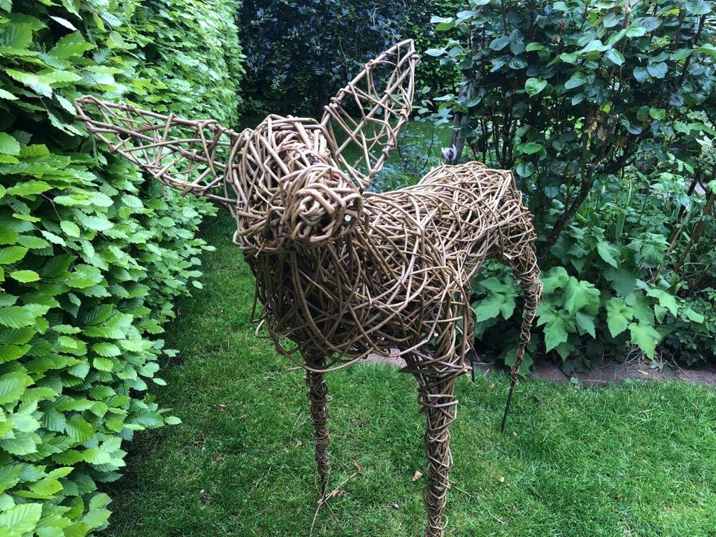
Slightly less, Javlin, the internal floor area is around 136 sq/ft, close to the size of your room. This is significantly bigger than my current modelling space.🙂 As for the eternal battle for exclusive ownership with the Admiral I know where you're coming from and share the pain. Work on my Victory build has been severely affected by the current shipyard in the smallest bedroom in the house having been seconded since last October as the storage area for decorating supplies for the Boss's interior design aspirations. This includes the redecorating of the whole of the top floor of the house including the bathroom. Victory has been stored safely under dust sheets while surrounded by paint tins, shower unit, screen and base etc. ceramic floor and wall tiles, adhesives, grout, new window blinds..... the list is endless..... All these projects, that had apparently been saved up for my retirement, are now happily completed and the only items causing loss of space are the six roof lights for the new workshop roof. When I move into the new model making area, she will take over the vacated space for her hobbies. She is also a very keen gardener so I've built her a store in the garden for horticultural tools and consumables to keep these out of 'my' space. I've been polite but firm, the ground rules have been set and agreed..... there is no negotiation..... which is why the unfinished workshop is currently home to this... ...a life size deer, woven from willow by the Admiral on a recent weekend course. The soaked sticks need to dry out thoroughly before the scuplture can be weatherproofed. But then.... it's off to adorn the garden, never to return....honest!
- 89 replies
-
- 12
-
-
-
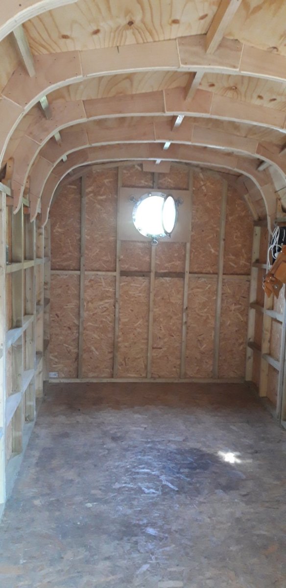
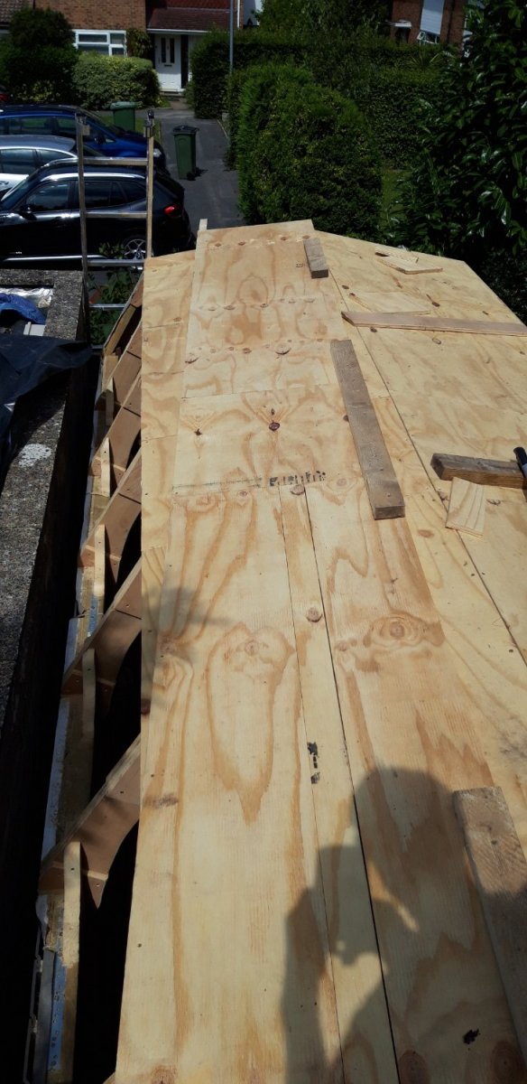
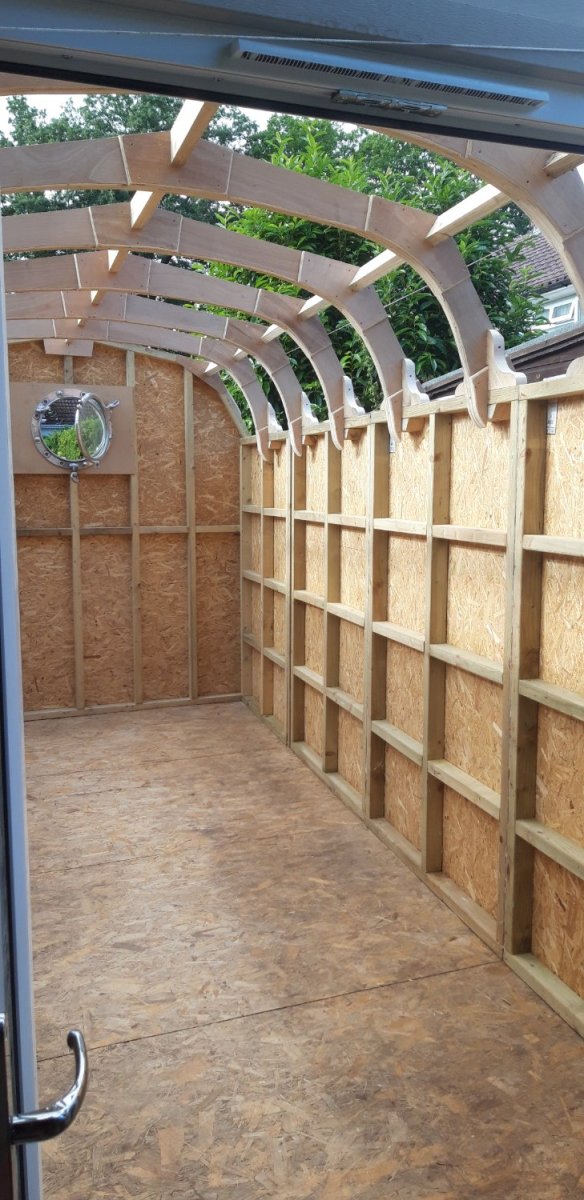
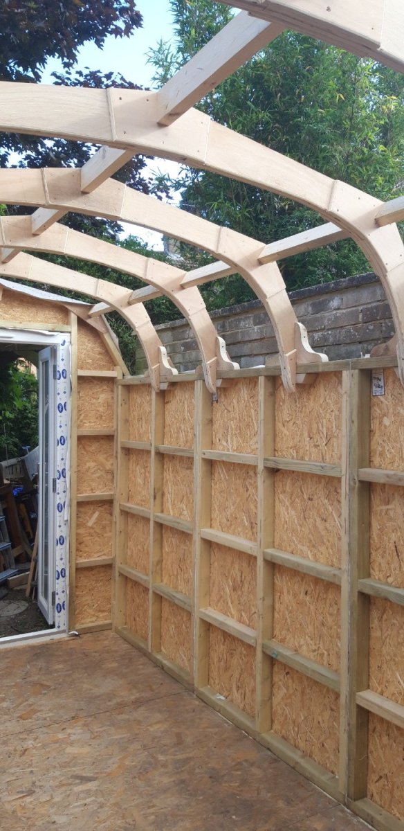
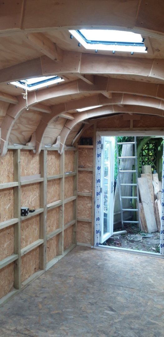
Thank you for your comments Egilman and Javlin, and for all those 'likes'... I must admit that I'm pleased with the way the roof framing came out. I'm planning to have as much of the 'ribs' as visible as the insulation and ceiling boarding permit. The next challenge will be the lower section of the roof on the left hand side. As can be seen in the last photo of my previous post, it's very close to my neighbor's garage wall making it difficult to add the covering to the ply once in postion. My current plan is to cut the ply for this section to size, partially cover it with vapour barrier, felt underlay and the first couple of rows of bitumen shingles, and then slide it down into position. I'll get this section sorted first and then, hopefully, the rest of the roof should be straight forward. Should be fun...😉
-
As impressive as ever Robert! Looking forward to seeing it mounted on that unique display base of yours.....
- 527 replies
-
- 1
-
-
- caldercraft
- victory
- (and 1 more)
-
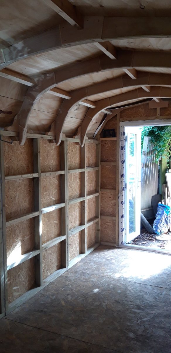
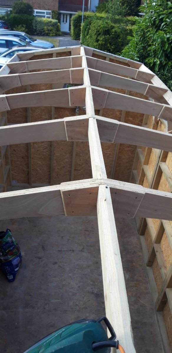
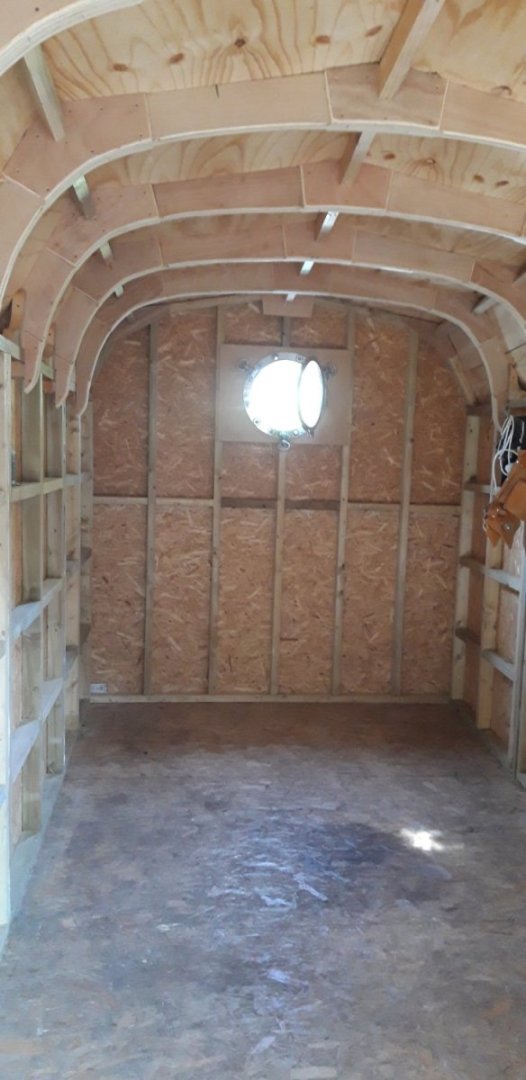
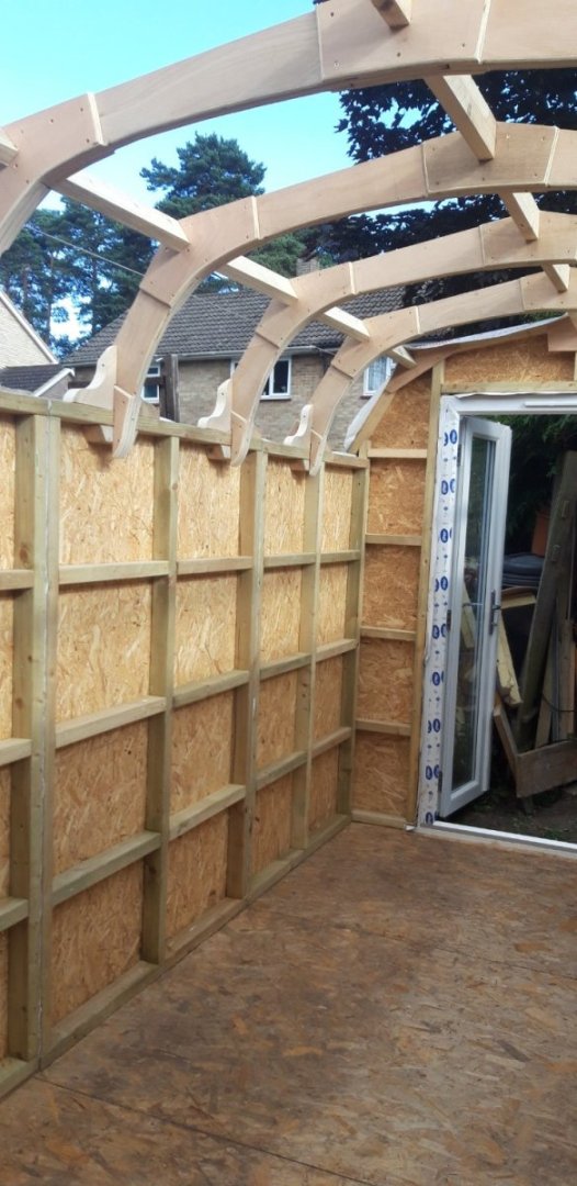
Well.... I could say that everything went as planned ..... but I'd be lying... The widths of each frame were spot on, but a couple of them needed a bit of tweeking, trimming or packing to to get them aligned to an acceptable standard. Took a full day to get them set up and to cut and install the top ridge. Today the side ridge spacers were slotted into place and finally the knees were fitted to brace frames and secure them to the side walls. All is now nice and rigid. Bit like making the tackles for every middle deck gun, the knees will all be hidden eventually, but we know they're there.... Next task will be to add the ply sheets. In the mean time the plastic sheeting and tarpaulin are back in place in anticipation of the heavy rain and thunder storms that have been forecast. Cheers, Graham.


- 89 replies
-
- 10
-
-
New blade arrived and I also took the opportunity to carry out some maintenance on the blade guides, the thrust bearing behind the blade in particular had seen better days. Spent the afternoon making the knees that will help fix the roof frames in place using some of the pine boards that were previously shuttering for the concrete base. Big day tomorrow ... weather promises to be dry, frames all sanded, other commitments cleared, so it's finally time to erect the roof structure ..... fingers crossed!
-
It's all coming together very nicely David. Impressive to put it mildly!
- 218 replies
-
- 1
-
-
- Victory
- Caldercraft
- (and 1 more)
-
Looking good Ron. I found this stage very satisfying as progress was quite quick through all the fore deck fittings. Lots of interesting little challenges..... have fun!😄
-
Beautifully executed. One of my favourite jets. Congratulations - all that effort certainly paid off!
-
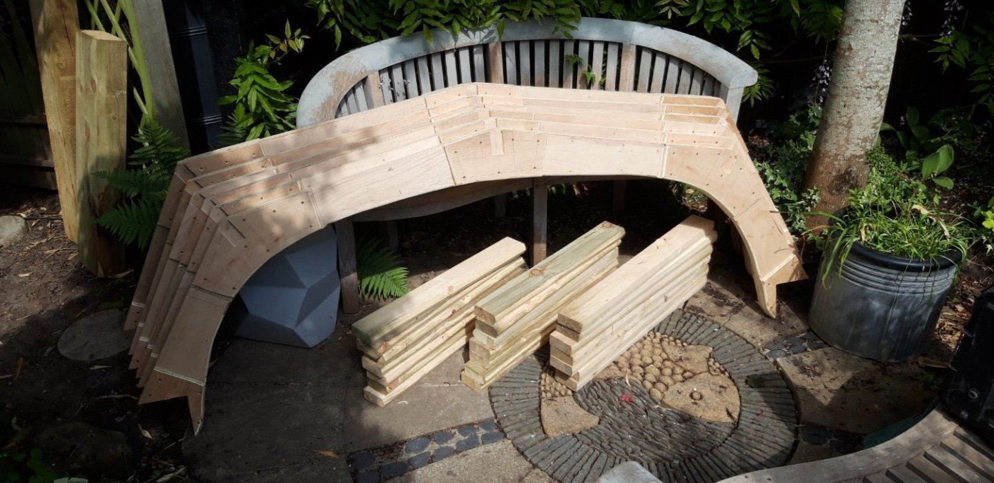
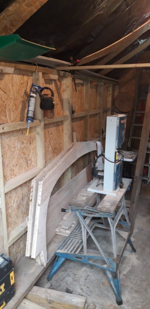
After a break to clear the Admiral's extensive project list, which apparently take precedent over a humble work space, the six roof frames are now complete apart from a final sanding. The ply reenforcing pieces glued and screwed to the corners have been modified to take the spacing beams. These beams have been machined to profile and are made from treated pine off-cuts from a flight of sleeper based garden steps built last year. The ends have been widened and extended following Ron's suggestions. I was hoping to cut pairs of knees to go either side of each end to fix the frames to the top of the wall panels but was scuppered by the bandsaw blade snapping. New blade due to arrive at the end of the week...... Cheers, Graham.
- 89 replies
-
- 10
-
-
Birchwood Casey solution can be a bit tricky at times! Over doing the soaking time was an issue I struggled with initially. A couple of strategies I found helped: - a short dunk agitating the components in the solution, rinse, repeat if necessary. - slightly dilute the solution. With those particular eyes I strung batches of them on a loop of cotton thread and treated them. Good luck! 🤞
-
Looking very good, Ron. 👏 Have you thought about using a brass blacking solution on those copper eyes?
-
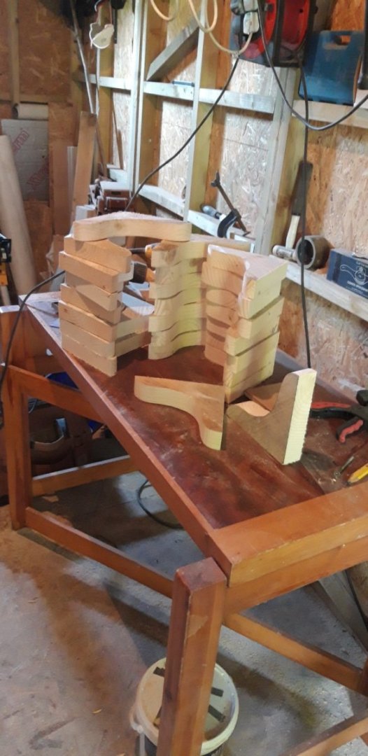
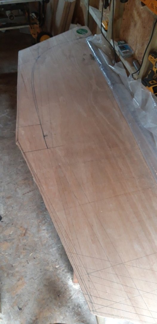
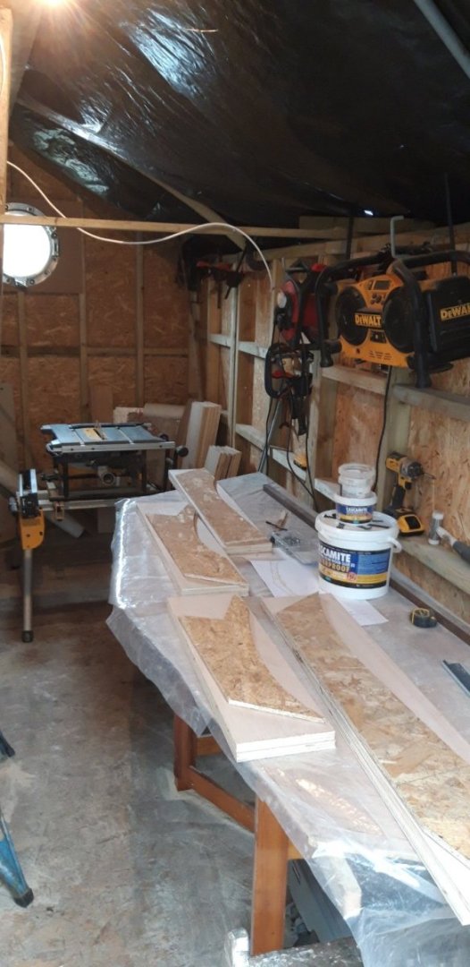
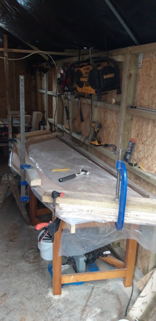
Please excuse the mess, but I've been busy! The roof truss building board, complete with all six variants laid out in preparation, has been set up as a workbench. The addition of a temporary light over it helped...... I've made a set of templates to mark out the four main parts for each truss Once roughly cut to shape these are adjusted to suit one of the profiles. and then the assembly is glued, nailed and clamped. Three down, three to go..... When all have been completed the building board will be cut up to make the plates that reenforce the corners and ends. Cheers, Graham
- 89 replies
-
- 11
-
-
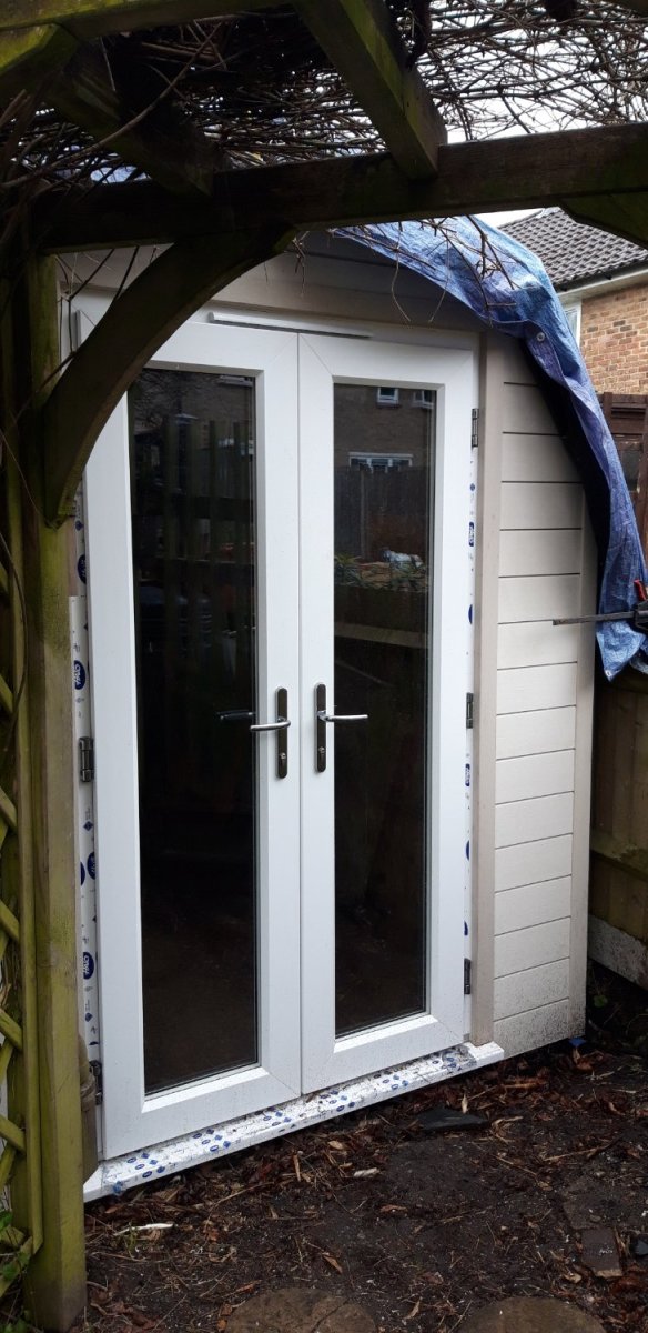
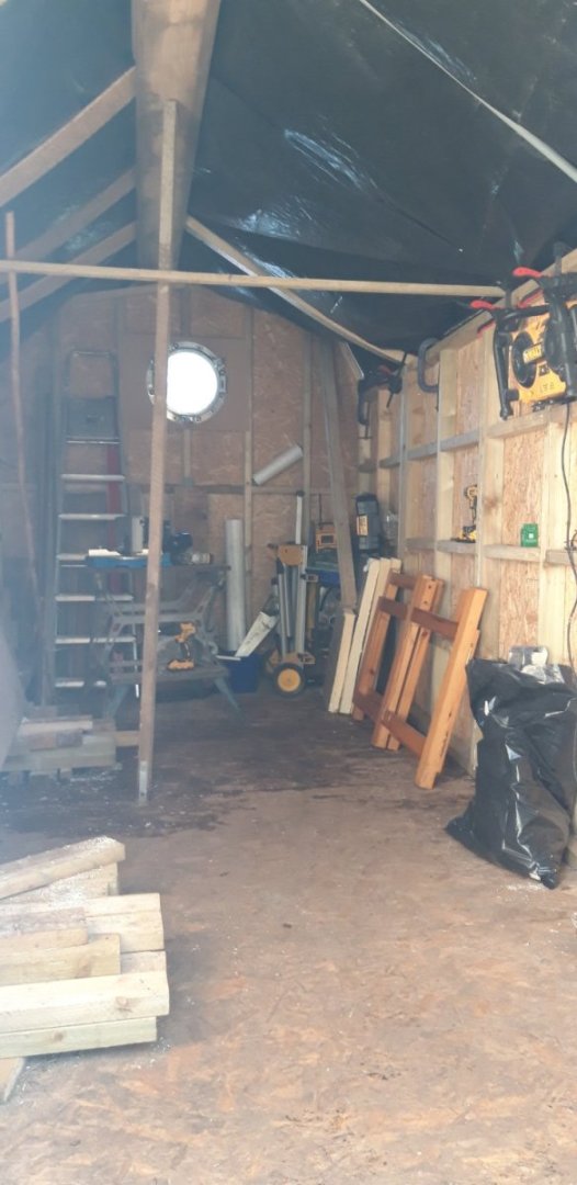
At last the door unit has been installed so the final wall could have its cladding added... The weather has held things up a bit - its been very wet recently. 'Catch 22' - to construct the roof trusses it helps to have a workshop, to use a workshop it helps to have a roof...... To protect the work completed so far weather proofing has taken the form of plastic sheeting and tarpaulins. A moderately successful solution, but not ideal, and high wind really tests its integrity. It's a bit dark inside, but usable. Measurements have been taken at the six positions where the frames will be fitted, for each of the four main elements that will form each truss. This has now been drawn out full size on a building board. The structural ply has arrived and my next task is preparing this for assembly. There are 18 parts for each truss frame, and each frame is slightly different to deal with the taper the workshop has in order to make the best of the available space. I have also received the six roof lights, bought earlier than needed to take advantage of a bulk purchase offer and to also beat a planned product price rise. These are currently stored in an already very cramped model making room...... but it will be worth it - eventually! Cheers, Graham.

- 89 replies
-
- 10
-