Charter33
-
Posts
455 -
Joined
-
Last visited
Content Type
Profiles
Forums
Gallery
Events
Everything posted by Charter33
-
Stunning work Greg. The detail and accuracy is very impressive. I'm really enjoying following your progress......
-
A stunning display of the model maker's art and attention to detail..... Brilliant. 👏👏👏 Well done!
- 206 replies
-
- 4
-

-

-
- Vanguard Models
- Brixham trawler
- (and 2 more)
-
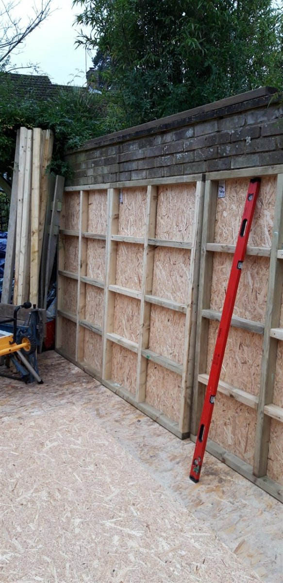
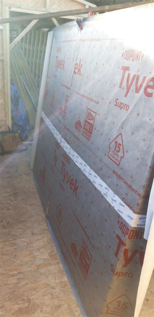
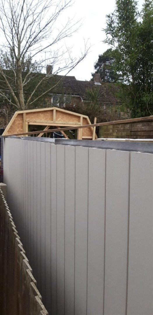
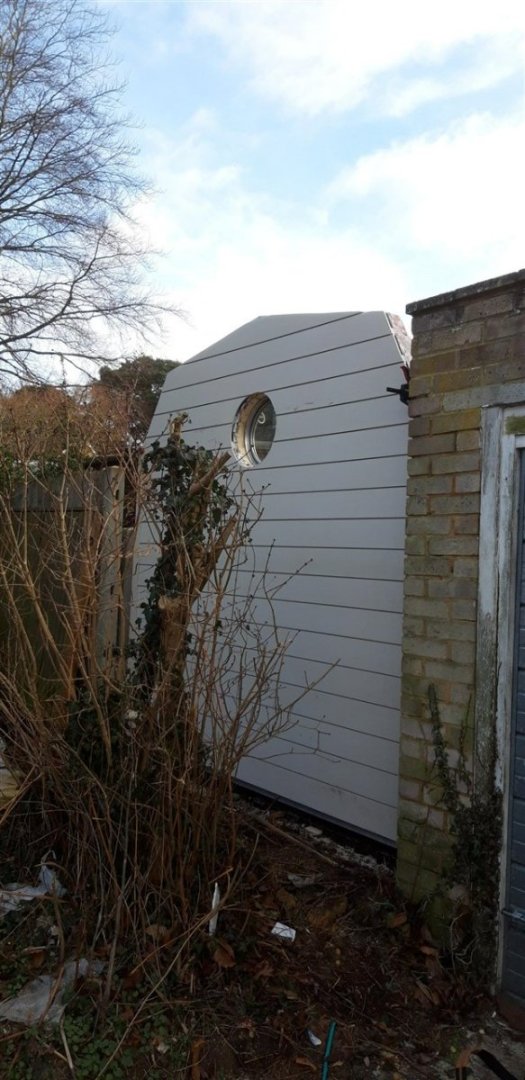
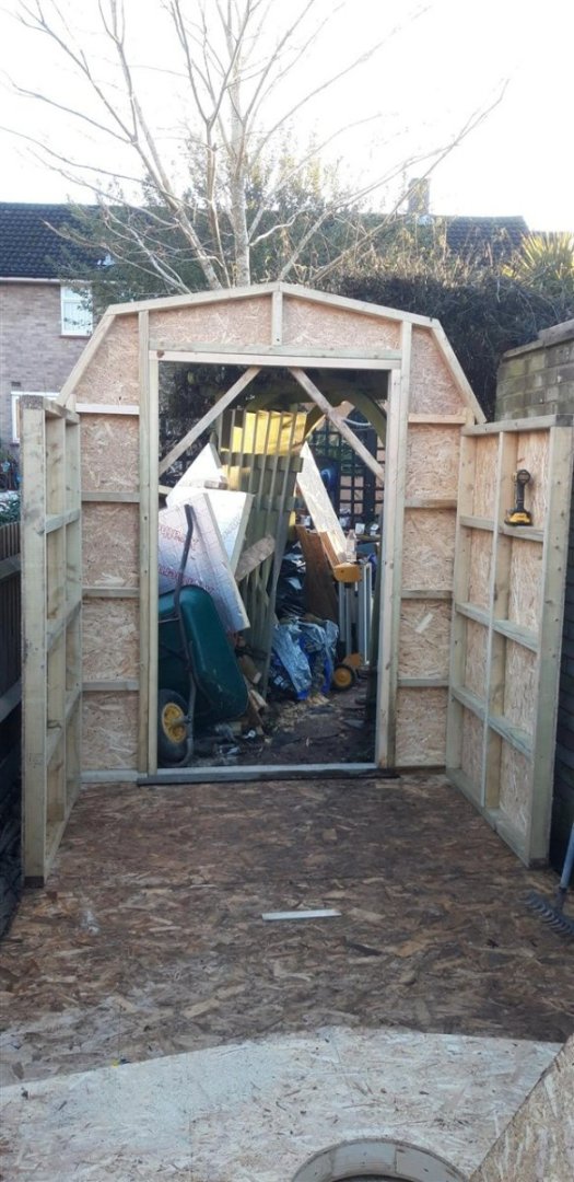
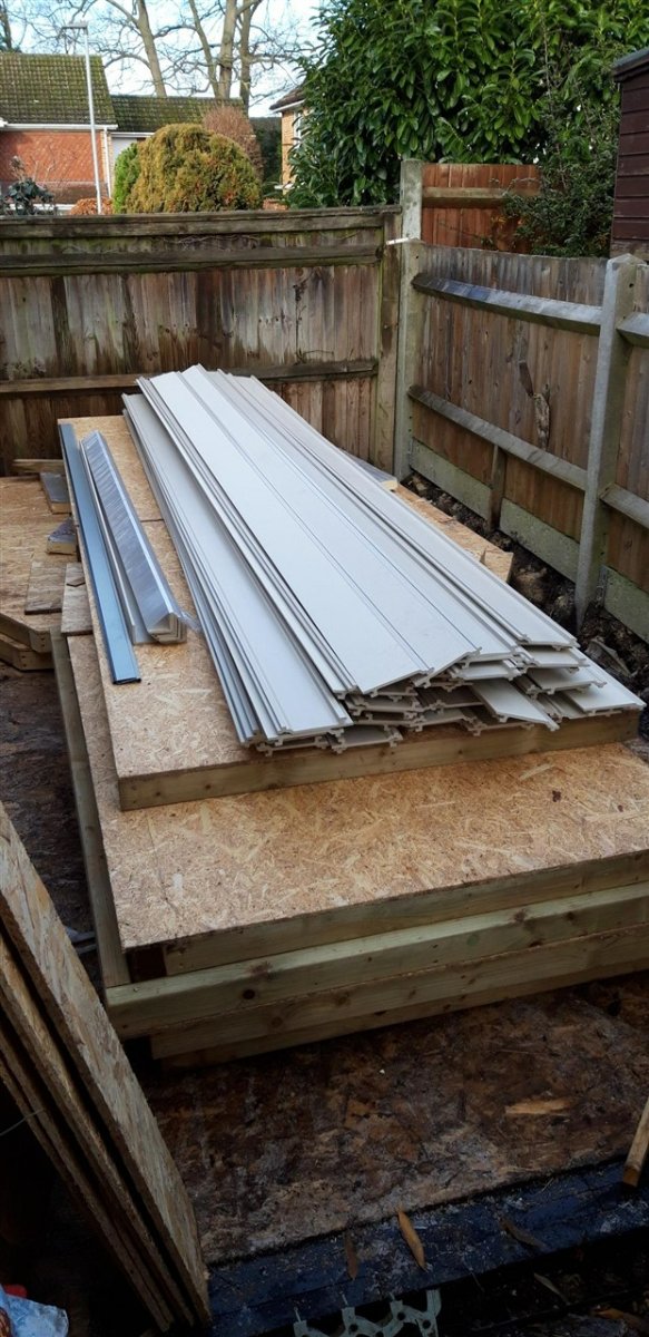
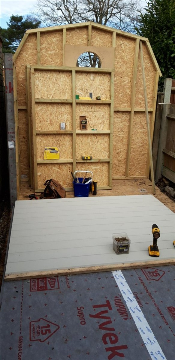
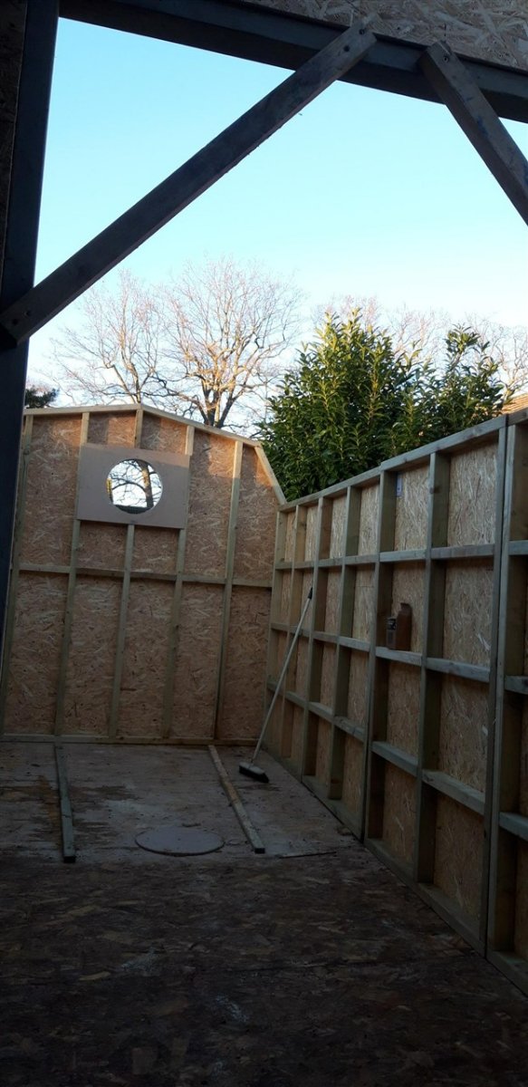
With the arrival of the cladding at last it's time to assemble this large 'flat pack' kit...... The height of the side walls was determined from the standard length of the cladding - 3.6 M. Cut in half and fitted vertically there was no waste. Two panels were clamped together and the run of cladding strips screwed on until the first two lengths were fixed to the second panel. At this point the panels were separated and the finished section lifted and screwed in position. Confession time.... my original plan was to clad each panel flat on the floor and then lift it and slide it into position. Maybe 30 years ago I could have succeeded ...... managed the first one, just! So a rethink led to the panels being covered in a more vertical position. The plan worked and each section snapped nicely into place Galvanized 3 x 30 mm straps set into recesses routed into the top of the sections bridging the joints stiffened the structure further. The cladding on the end panels runs horizontally. On the far end the four 20 dia. x 100 mm coach bolts that secure the porthole had to be added first. This meant temporarily fitting the porthole. Careful trimming with a jigsaw followed by a large drum sander completed the shaping of this feature. After this picture was taken the fence panel was dragged back into place and secured for the final time. Cladding the near end panel will wait until the door has been fitted. This is due to arrive at the middle of next month. For now this end has been left with the vapour barrier for protection. Spent the afternoon clearing up the site and a quick trip to the local recycling centre to dispose of a car full of offcuts etc. that were to small to be of any further use. Also needed to clear the part of the garden I've been using to store materials as the Admiral's spring bulbs are pushing themselves up in the adjacent flower beds! Time to start working on the roof...... Cheers, Graham.


- 89 replies
-
- 12
-
-
Impressive work with those sails Andrew. The detail on the deck is a whole new level too. Looking forward to seeing that mainsail!
- 206 replies
-
- 4
-
-
-
- Vanguard Models
- Brixham trawler
- (and 2 more)
-
Might it be referring to having the copper sheathing hammered or beaten to final shape to match the timbers ie. fine tuning or 'dressing' the sheet for a good fit?
-
Incredible wood carving. Reminds me of the work of Grinling Gibbons, in miniature. Regarded as one of the finest wood carvers, he died 28 years prior to the launch of Royal Caroline..... Such stunning detail!
-
Good to see you're back in the shipyard Dave, and your Mayflower is looking great. I will be continuing to follow your progress with eager anticipation! Cheers, Graham
-
A beautifully engineered and creative solution to displaying your exceptional Victory build, Robert. Pure genius! 👍
- 527 replies
-
- 3
-
-
- caldercraft
- victory
- (and 1 more)
-
Good idea to extend the trusses down further and widening them where they rest on the walls, Ron. The metal straps I'm thinking of using are 30 mm wide and will screw to the top horizontal CLS timber. I could add them to the sides as well - they will all be hidden once the wall insulation and interior facing boards are in place. I'm also planning to add some additional bracing between the trusses too. I've dropped the number of trusses from seven to six to increase the width between them for the roof lights and one other advantage of this is it moves them away from being directly in line with the vertical wall panel joints. As for snow loads - this far south we rarely get more than a couple of inches, 4"- 6" is regarded as extreme. Unfortunately in the UK anything above 1/2" is enough to bring traffic chaos and bring the railways to a halt....😂
-
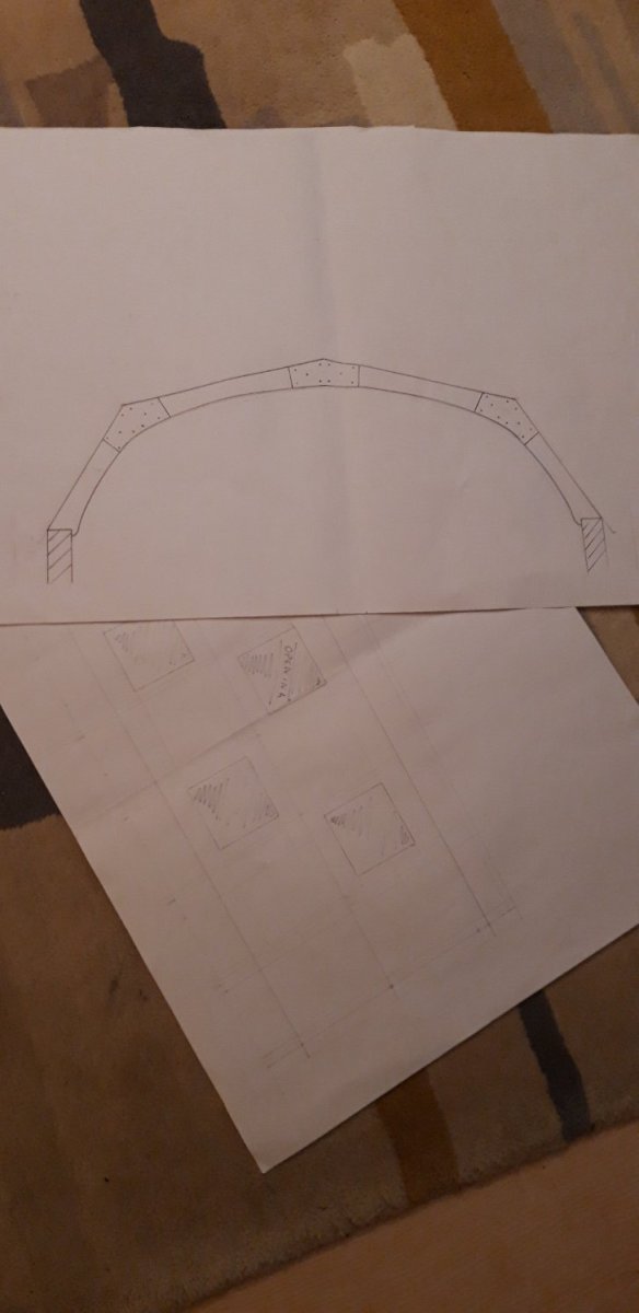
The plan is to build the intermediate trusses using structural ply, Ron. Something like this: The angles are constant, just the lengths of each member need adjusting, and I can get these measurements once the walls are erected. Fitting six of these trusses will give me room to comfortably fit the 500 mm square roof lights. I'm also planning to re-enforce the joints where the side wall panels meet with galvanized metal straps on their top edge to hopefully minimise any tendency for them to distort under load. Might add some collar ties as well, doubling as storage supports for longer lengths of timber. Cheers, Graham.

- 89 replies
-
- 10
-
-
Hi, Thanks Andrew, it all seems to be coming together at last. Looking forward to completing the weather proof shell so I can work on the interior ..... just the small matter of the roof to overcome, but I'll deal with that hurdle once the walls are finally erected - working out the dimensions of the roof trusses will keep me busy with each one differing in size due to the taper. Thanks for the advice Jaager. The condensation issue has been given a lot of thought. The Tyvek is already here and ready. This vapour barrier will go over the outside of the OSB and under the composite cladding. The profile of the system I'm using (Claddo) leaves a good air gap behind it. Wall and roof insulation might end up Rockwool, or possibly a natural wool fleece product. As I hope to spend a lot of time using this building it will need to have some form of heating to make it comfortable in the colder months and also to protect the equipment that will be in it. The French doors have also had the trickle vent option for ventilation too. Earlier in the design process a curved corrugated roof was a strong contender - sort of like a Shepard's hut without the wheels. The difficulty of adding affordable roof lights put a halt to that idea. Not wanting to have a flat roof or a normal pitched roof the 'gambrel' style seemed a workable alternative, the inspirational spark for this actually came from Knocklouder's pictures of his vegetable and herb garden! The products Kalwall produce are very impressive but unfortunately my budget is definitely limited! I have found a small company in West Sussex called Activent who specialise in roof windows, fixed or opening, single or double glazed, specifically for wooden garden buildings. These seem ideal for my purposes and I'll probably go for the fixed double glazed version with an opening one for those times when a bit of extra air flow is need. Grotty weather back in force today, but the cladding order has now been placed and it's arrival eagerly awaited! Cheers, Graham.
-
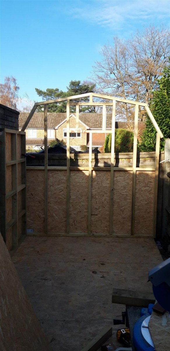
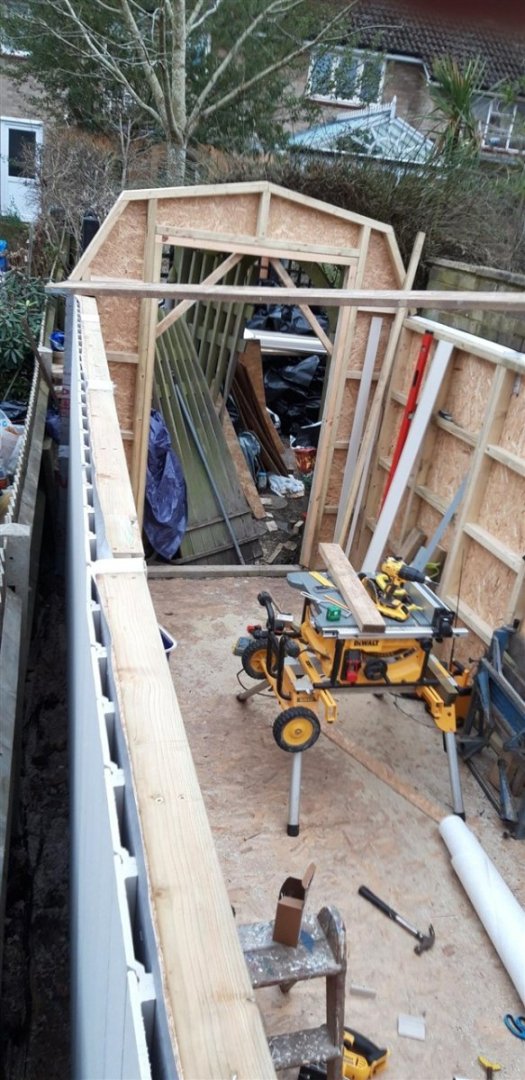
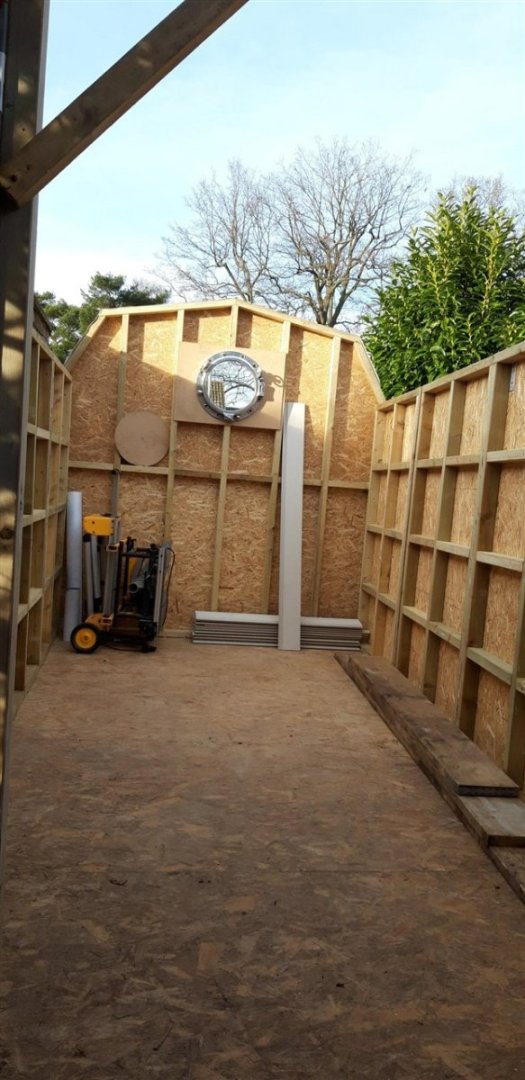
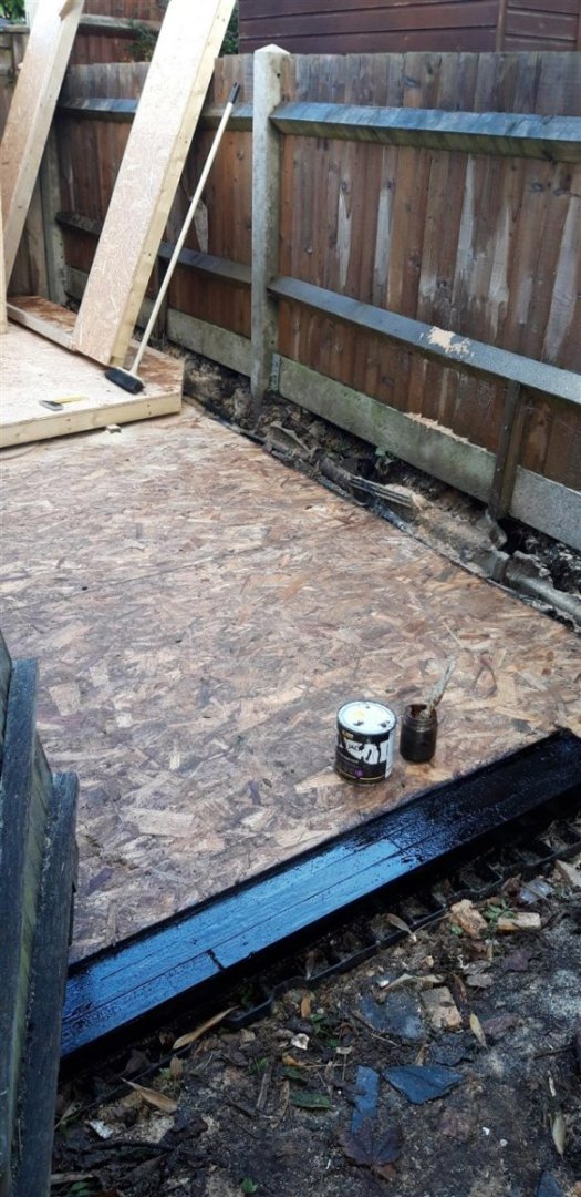
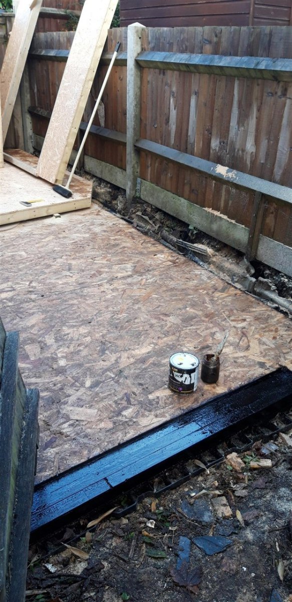
The weather, plus seasonal events have slowed progress down but today, the first in a while with no rain forecast, enough work has been done to warrant an up-date. Christmas Eve: I made a MDF routing jig for the porthole which includes the position of the mounting holes. The plan is to use four 20 mm x 100 mm coach bolts with dome head nuts for the main fixing but with the remaining holes covered with the same nuts but on dummy wooden pegs to save a bit on the expense. The position of the porthole has also been lowered a touch. A profile cutter in the router shaped the additional timber framing. After roughing out the hole in the OSB board with a jigsaw the opening was worked from the other side with the router. Today, after machining the recess for the door cill, all external edge timbers of the base were given a couple of coats of bitumen paint to seal and improve water resistance. The final wall panel, the near gable end with the French doors, was framed up on top of the far wall to ensure the roof angles were maintained. It was built around a temporary timber door frame made to the exact size for the unit on order. Couldn't resist the temptation to slot it all together........ just to check.... With the sun beginning to set it was time to return it all to it's flat pack form and under tarpaulins to await the arrival of the composite wall cladding. Happy New Year
_1280.thumb.jpg.d9e4ecbf9e6a57d6cea9d1c3d2b9c486.jpg)

- 89 replies
-
- 12
-
-
Hi Bruce, Not to sure if this technique would be appropriate as I don't know if it would work for your particular application, but one trick I use when wood turning is to glue wood together with standard PVA, but with a piece of paper in the joint. It holds things together well enough for quite aggressive shaping but can be split apart once the job is done. A sharp chisel usually does the trick. The paper/glue left on the joint surface can then be sanded or scraped off..... Another possibility might be to use a hot melt glue and then heat the wood after shaping. Seen this done but to be honest I haven't tried it myself. Good luck! Cheers, Graham.
-
Excellent work there Ron.... looking good...👏
-
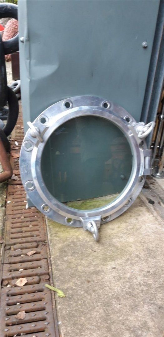
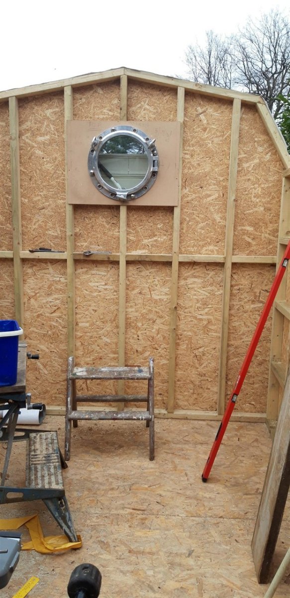
Well.... what a day! This could just as well been posted in the 'What have you received today' thread 🙂 I wanted a window in the far gable end that would increase the amount of natural light to the 'clean/dust free' model making section of the workshop (the Captain's day cabin?). I thought it would be appropriate to have some sort of nautical theme as a nod to the workshop's primary use and have a few ideas about how to do this. Then the Admiral asked for ideas for a Christmas present. "A porthole would be nice...." Today we drove over to Trinity Marine near Exeter. Remember when you were a child and were taken to the most amazing toy shop and you felt like all your Christmases had come at once? This marine reclamation/salvage company has some jaw dropping stuff. Their website is impressive, but really does not do justice to the stunning stock they have - for example the very detailed model paddle steamer that currently has pride of place in one of the two display showrooms -it must be at least 8' long, or the model of a French frigate, or the gear reclaimed from HMS Hermes....... To call the place an Aladdin's cave is an understatement and I recommend a visit if you are ever in the area. trinitymarine.co.uk if you want to browse their website. So, I am now the proud owner of a 19" diameter, aluminium opening porthole reclaimed from the MV Orient Well. and one of my next tasks is to adapt the timber framework to accept it. Christmas has come a bit early this year 😁 Ho ho ho Cheers, Graham.
- 89 replies
-
- 19
-
-

-
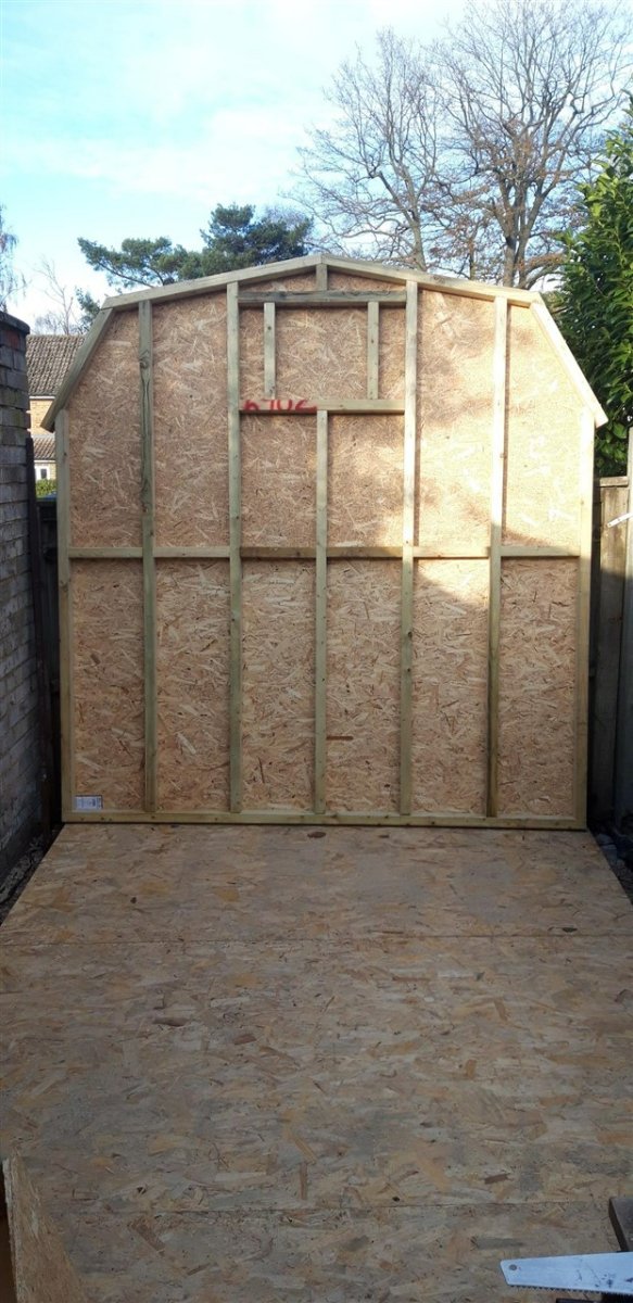
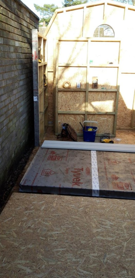
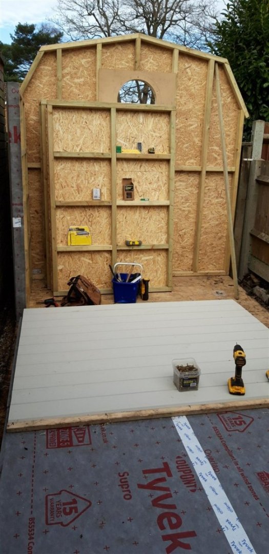
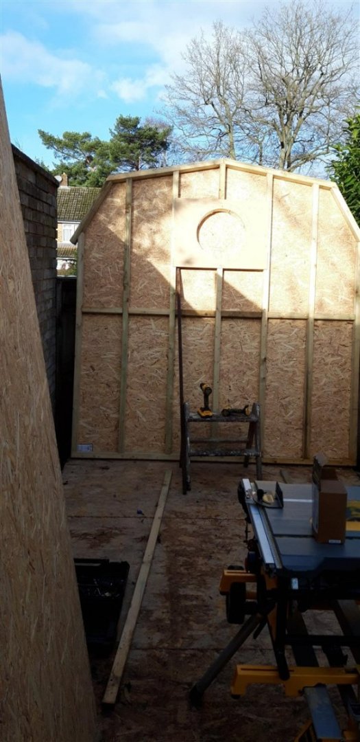
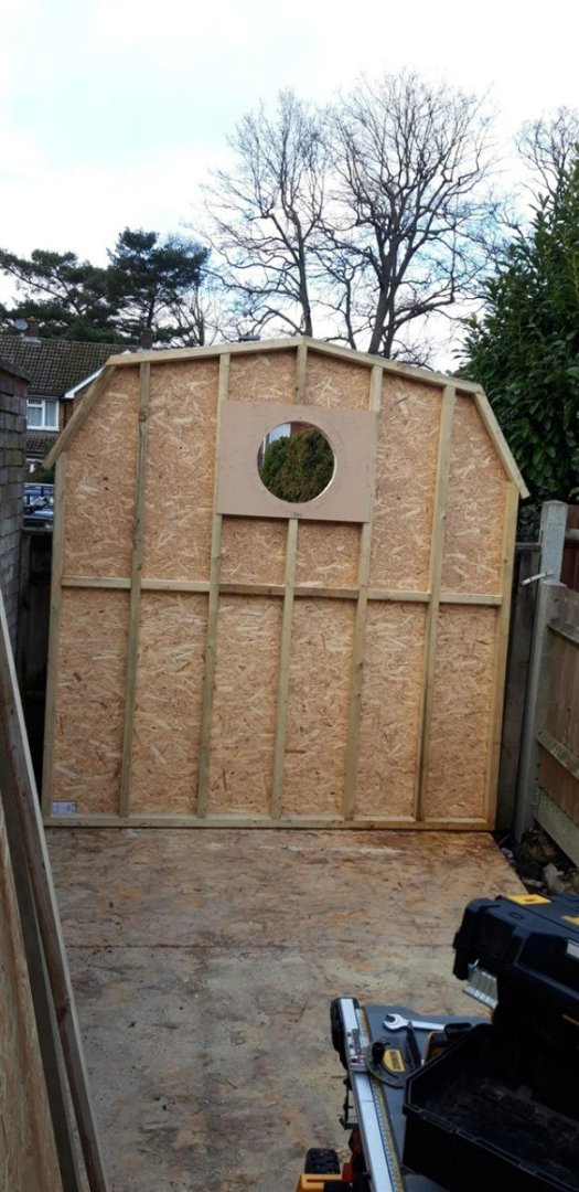
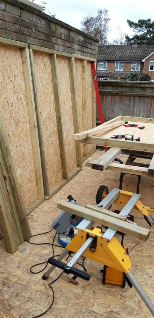
Thanks for the 'likes'! Moving on to the walls...... Side walls comprise of four 4' wide x 6' high treated softwood frames faced with OSB board each. A modular design with each section to be covered in breathable membrane and composite cladding. Completed sections will then be bolted together and secured to the floor......... Far gable end next. Framed and faced the same way but it will be covered in membrane and clad once all the elements are finally assembled - I can just about manage to lift this panel on my own..... no chance if it's clad! The bottom fence panel will be temporarily removed to do this. First test assembly........ ....... all good and now fully faced. A meeting with the surveyor from the company who are making the French doors ironed out the finer details of the nearer gable end, and this will be the next stage. Making progress! Cheers, Graham.
_1280.thumb.jpg.467af2dff173071e2c52a641fbfb9122.jpg)


- 89 replies
-
- 17
-
-
Green over brown or brown over green? The answer is 'Yes, either way.' Which ever the way, you're displaying it brilliantly... keep up the excellent work! Really enjoying this build!
-
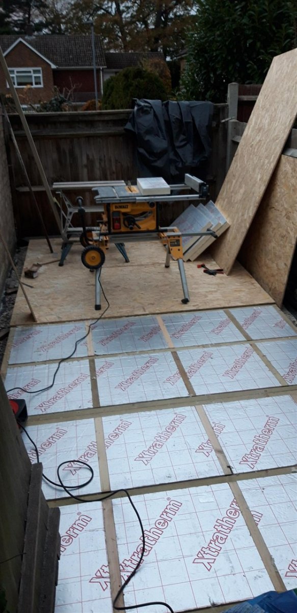
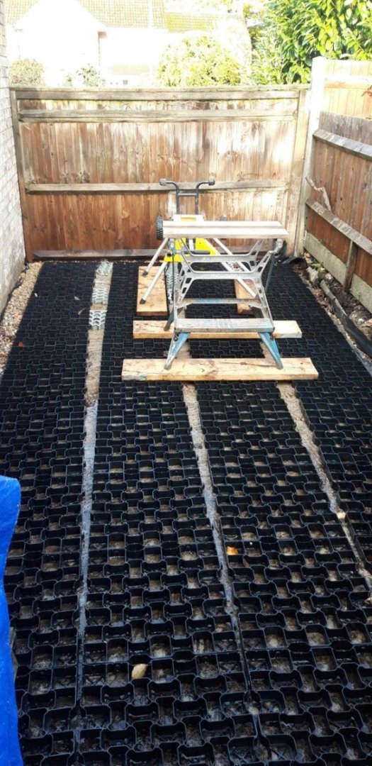
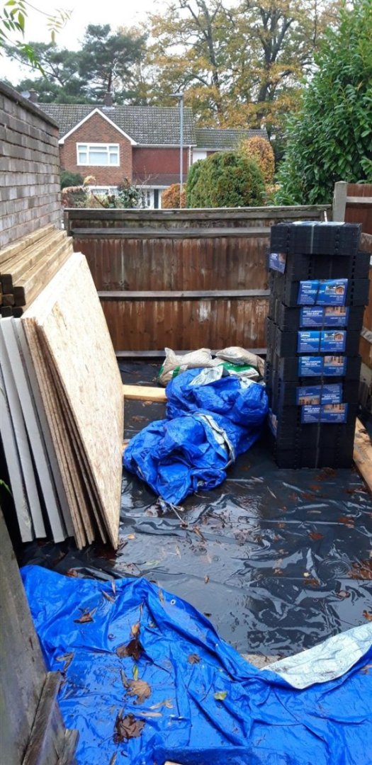
Air gap forming base roughly in place and showing the issue of the tapering plot. The gravel/weed control matting drainage channel around the slab works well as proved by a morning of torrential rain. Construction of the wooden floor went as planned. First two panels completed, the other two internally braced and with the insulation panels in place. Twilight coming on....... ..... but all finished by the end of the day - thanks to the built in LED lights on the cordless screwdriver. Had to clear up and cover things with tarpaulins by the light of the streetlamp behind the fence, but all is now weather protected, and this week target has been met. Walls next...... Cheers, Graham.

- 89 replies
-
- 10
-
-
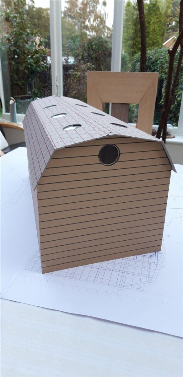
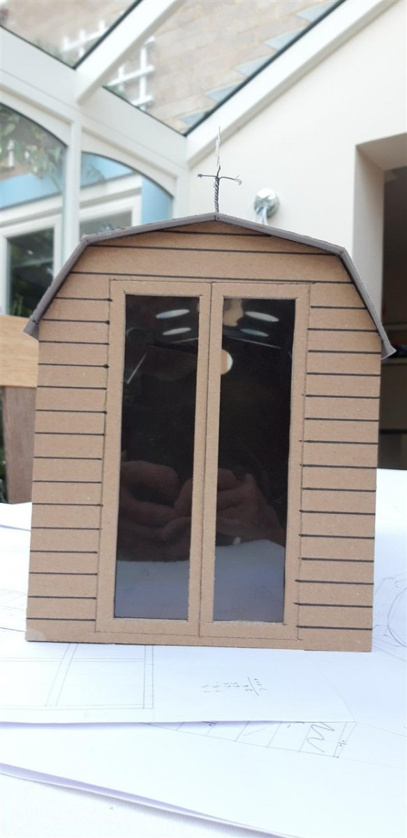
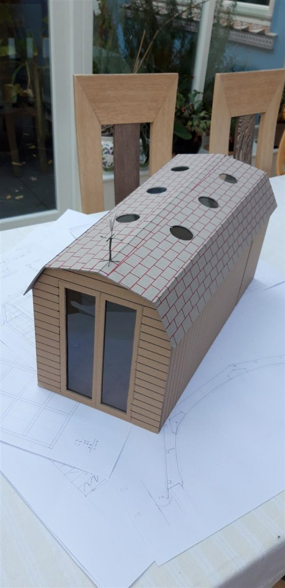
The appropriate dimensions are: 5 M (16') long, 2.5 M (8') to the top roof ridge, the far end, with the round window, is 2.4 M wide, and the width tapers to 2 M (6' 6") wide at the end with the doors. These sizes will maximize the area available while still conforming to planning regs. The rain that had been forcast held off long enough for me to sort out gravel drainage channels around the concrete slab and to lay the plastic air gap forming base. It was dark by the time I'd finished for the day, so no pictures today.
-
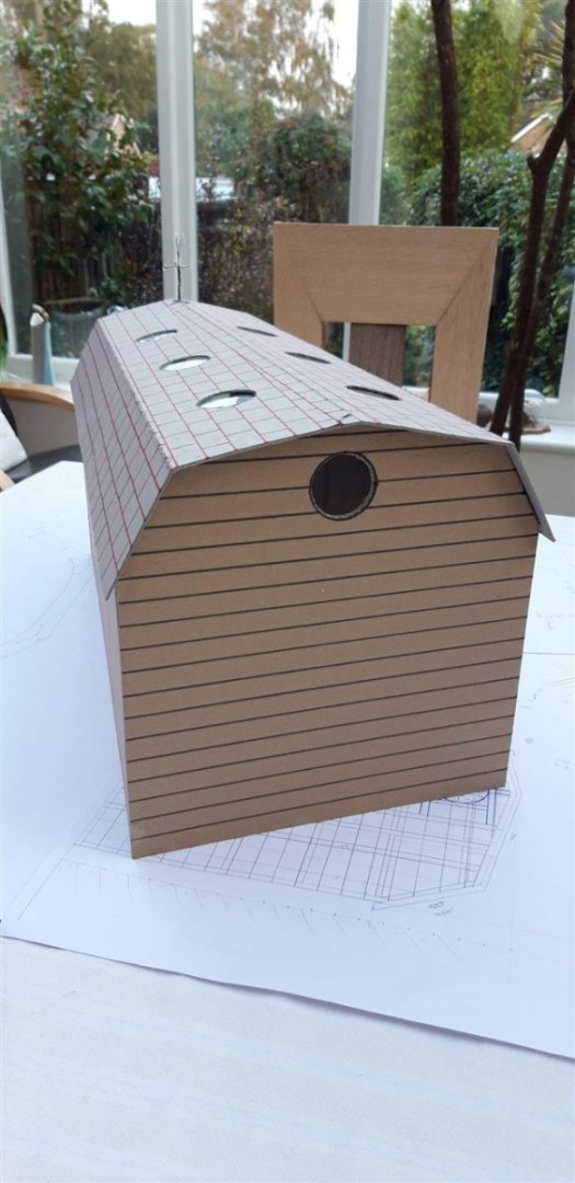
With the groundwork and the concrete slab base now done, as described in the 'What have you done in the garden' thread, it seems about time to branch out into a build log of its own. Initial design thoughts have evolved, and evenings have been spent researching materials, techniques and costs and these were used to draught out some plans. A quick 1/10th card model helped with visualizing the concept. I no longer have access to the CAD packages I used to work with, so it was back to earlier tech ie. Tee square, drawing board, set squares and sharp pencils - happy days! A few finer details still need to be resolved. These include things like the position and types of roof lights. With the structure enclosed on three sides the roof is the only practical source of natural light. At the moment I'm leaning towards using sun tunnels, but this may change. Another modification to the outline 'aspirations' explained before is the move from a half glazed stable door to a pair of fully glazed French doors to also improve the amount of usable daylight and to provide wider access. Limitations in terms of access to the site, limited storage and construction space will need to be carefully managed but my plan seems viable and I'm now in a position to start building. So today the first batch of materials arrived - enough to construct the floor. This insulated OSB box, complete with an air gap between it and the concrete, will eventually be clad with T&G floorboards once the shell is complete and weather tight. Now...... if the rain would only stop falling, I could get started...... Cheers, Graham.


- 89 replies
-
- 11
-
-
Turn a scalpel blade into a saw
Charter33 replied to bruce d's topic in Modeling tools and Workshop Equipment
Another vote of thanks for posting the link to the scalpel/saw modification, I will be giving this a try for certain. I also watched the rest of this episode - love watching a craftsman who clearly enjoys his work and takes the trouble to share his skills. I too was intrigued by the heat treatment alluded to for the jewellers graver tools using beeswax. This was the first time I've come across 'hardening and tempering' being carried out together at the same time. I was always under the impression that high carbon steel had to be heated and then quenched to harden it ( the carbon going into solution and being trapped within the structure resulting in an extremely hard but very brittle material) followed by a separate re-heating (tempering) to a lower temperature that enabled some of the carbon to come out of solution - a lower temperature for tempering giving a harder material suitable for a tool such as a scriber, a slightly higher temperature for tools that are subjected to impact and therefore needed a degree of flexibility such as a cold chisel. Annealing is heat treating a metal to make it as soft as possible so that it can be more easily worked. Metallurgy is one heck of a science with so many variables. The specific carbon content, and the presence of other alloying metals in some cases, results in a vast range of possible physical properties that can be fine tuned to meet a requirement. All this is achieved using different temperatures, holding at this temperature for different periods, and the rate of cooling. I can only assume that the process described in the video has been found to produce the properties needed for a graver tool, ie. the ability to retain a hard and sharp edge to enable it to remove metal skilfully and accurately in the hands of a talented artisan. I'll be giving this method a go too! Cheers, Graham. -
Really enjoying following this excellent project, including all the additional information that has been posted recently on pulleys. Bandsaws also use the principle of a slightly radiused crown to the pulleys to ensure the blade tracks to the centre. Looking forward to seeing the lathe hooked up to the engine and running! Cheers, Graham.
-
Can't speak specifically about the 1.5 mm sq. walnut as I bought extra from a local model shop to do that particular additional feature, but so far I have found that Jotika/Caldercraft have been generous in the quality of various materials, both wood and metal, that they provide. Even having had to re-do some of my build due to inexperience/incompetence there hasn't (yet!) been the problem of running out of stock. Cheers, Graham
-
I had a quick look and there are plenty of really good video tutorials out there on the cuttlefish bone casting technique. Its a very old traditional method but one word of caution - the pouring of the molten metal is best done outside or in a very well ventilated area - the smell of the charred bone is quite strong! Graham.
-
Impressive work there Ras. Another material that you could use for a mould when casting is cuttlefish bone. Inexpensive and available from pet shops jewellers often use it for a 'one off' item. You can get a smoother finish to the casting if you shape the cavity by pressing into it rather than carving. I'm sure that there will be tutorials on-line out there to help you. Good luck! Graham


_1280.jpg.d33180424abd8a9617587193b3566d2a.jpg)


_1280.jpg.431085d67309829d7baedfeef9fc1b61.jpg)