


Charter33
-
Posts
422 -
Joined
-
Last visited
Reputation Activity
-

 Charter33 got a reaction from CraigVT in HMS Victory by Charter33 - Caldercraft - Scale 1:72
Hi,
Tackling the wales proved to be fairly straight forward.
After taking measurements from the plan and transferring them onto the hull, a strip of wood was pinned on these marks and, after a little ‘fine adjustment’, the curved lines were marked on.
The majority of the prepared pieces fitted straight on and CA glue was used for bonding. At the bow and stern some additional shaping was required together with gentle bending with plank ‘nippers’.
These photographs show the work in progress and the final results.
Drifting randomly through the wide ranging posts on this site the other evening I came across many superb examples of the model makers art that reminded me of a time, back in the mid-1960s, when the ‘Birthday treat’ of choice was a trip across London to visit the Cutty Sark followed by the model ship galleries at the National Maritime Museum, Greenwich. It was these amazing models, mostly ‘plank on frame’, that sparked a lifetime’s interest. Sadly these wonderfully detailed models are no longer on display although they can be examined to some extent on-line.
Why am I rambling on about this? Well – one of the sections I was exploring that started this reminiscing was the HMS Triton project. WOW! My head is telling me to keep focused, the ‘Victory’ journey has a long way still to go, my heart is saying – what a challenge! The build logs, both completed models and works in progress, are very impressive. It costs nothing to start planning… the keel plans are easily down loaded,…. and there just happens to be a very helpful and friendly print shop less than a mile away ……mmmm
Meanwhile, it time to start lining the gun ports.
-
Charter33 reacted to dj.bobo in RNLB Ruby & Arthur Reed 2 by dj.bobo - FINISHED
Good evening to everyone, work continues with deks lamps .
Have a nice evening.
Adrian .
-
.thumb.jpeg.fc5d633a7b34428fcf19419a73d56d55.jpeg) Charter33 got a reaction from EricWilliamMarshall in HMS Victory by Charter33 - Caldercraft - Scale 1:72
Charter33 got a reaction from EricWilliamMarshall in HMS Victory by Charter33 - Caldercraft - Scale 1:72
Hi Folks,
The last of the three ’Victory material’ challenges is the construction of three ‘pedestals’ on which the finished model will be mounted. Final completion of the model is still a considerable way off – but retirement is probably going to strike before this and it makes sense to tackle the task while access to the workshop equipment is still possible. (well, that’s my excuse and I’m sticking to it…)
There are a number of unknown factors that could affect this mini project: Will it be possible to turn the metal in the first place? – I’ve come across some metals in the past that have a skin so hard it knackers the cutting tool in seconds, and what kind of finish will it be possible to achieve? Only one way to find out.
The rod as supplied…..pretty uninspiring, about four inches long and a little less than an inch in diameter.
First job is to face off the ends of the bar.
…..then skim the bar to remove the corrosion. First question answered – oh yes, it will machine. It cuts in a similar way to mild steel and is relatively soft ….
The finished billet is then cut into three blanks…
I’ve made the decision to turn the base of each column down and thread them M10 x 1.5 initially to enable each piece to be mounted on a mandrel for further machining, meaning I won’t have to hold the blank directly in the lathe’s chuck, and eventually to fix the pedestals to the wooden base.
Mounted between the mandrel and a revolving centre, each blank is machined to profile with a round nosed tool. The final finish is achieved using emery cloth followed by 600 grade ‘wet and dry’, and finally the same grade of abrasive paper lubricated with a light oil.
Just like turning legs for Windsor chairs, the first one is quite straight forward – its’ getting the others to match that provides the challenge!
Last task is machining the slot for the keel to fit into, using a universal milling machine fitted with a 4mm slotting bit. The final slot was 6mm wide. The pedestals have been previously been drilled on the lathe to take the 1/8th” silver steel rods that will extend up into the tubes set into the hull structure (see my first ‘post’).
Done and dusted….
Cheers for now,
Graham
-

 Charter33 got a reaction from CaptnBirdseye in HMS Victory by Charter33 - Caldercraft - Scale 1:72
Thanks for dropping by Marc, here is yet another jig!
Decision made – I’m going to stick with the approach given in the manual and work up from the keel – thanks Steve for the ‘nudge’ that finally swayed me.
After several sessions I have now fitted about 10% of the copper plates. It was always going to be a long haul, but so far it’s been fairly straight forward and surprisingly therapeutic!
One aspect that has been giving me food for thought was how to deal with the keel. I wanted to cover the bottom of it with plates folded evenly over the edges. With the keel 5 mm thick and the plates 6 mm wide this means a ‘return’ of 0.5 mm on the side of each plate. Early attempts with flat pliers and then brass soft jaws in a bench vice failed miserably ……
With approximately 60 plates needing to be shaped some kind of simple former was going to be required. This is what I came up with:
The main body consists of two 60 mm lengths of 5 mm square mild steel bar. The lower part has a shallow recess equal to the length of a copper plate filed into it while the upper bar has two grooves filed in with a ‘three square’ needle file to provide clearance for the raised rivet heads that run across the ends of the plates. I couldn’t find any small diameter socket headed machine screws to apply the clamping pressure in the workshop so resorted to cutting M3 x .5 threads on the pins of a couple of plated brass ‘push buttons’ from old 1970’s telephones that were rattling around at the back of a cupboard – knew they’d come in useful one day ….. Clearance holes in the top bar and suitably threaded holes in the lower bar finish the former.
The plate is put in place, but first checked to ensure that the rows of ‘rivets’ on the side are equally spaced from the edges – this sometimes varies considerably.
After clamping the protruding edges are pushed by thumb in the right direction and then a piece of softwood dowel is rolled along the edge to complete the bend.
... and the job's a goodun...
I hope this will be of some use to other builders.
Cheers,
Graham.
-
 Charter33 got a reaction from Tallshiptragic in HMS Victory by Charter33 - Caldercraft - Scale 1:72
Thanks for your kind comments guys.
Robert - your Victory build log is one I often refer to when I need guidance. I wish I’d found your tip on using filler blocks between the bow and stern bulkheads before I’d moved well into the first planking …..
Michael – after a day at the front of a classroom copper plating is a great way to ‘chill’! But you’re right, I do need to break away at times and am working on various jigs to help with adapting and constructing the cannons at the moment. For a really mind numbing task try making the copper plates themselves. I’m currently making half a dozen from copper reclaimed from the scale 1:1 example residing in Portsmouth. Each plate has 40 simulated rivets, each punched individually – I have managed to do two consecutively before having to resist the need to scream or hit the Scotch. …oh, and the Admiral is also adept at interrupting the work flow with numerous little diversionary tasks ….. bless her!
Cheers for now,
Graham.
-
 Charter33 got a reaction from maddog33 in HMS Victory by Charter33 - Caldercraft - Scale 1:72
Thanks for dropping by Marc, here is yet another jig!
Decision made – I’m going to stick with the approach given in the manual and work up from the keel – thanks Steve for the ‘nudge’ that finally swayed me.
After several sessions I have now fitted about 10% of the copper plates. It was always going to be a long haul, but so far it’s been fairly straight forward and surprisingly therapeutic!
One aspect that has been giving me food for thought was how to deal with the keel. I wanted to cover the bottom of it with plates folded evenly over the edges. With the keel 5 mm thick and the plates 6 mm wide this means a ‘return’ of 0.5 mm on the side of each plate. Early attempts with flat pliers and then brass soft jaws in a bench vice failed miserably ……
With approximately 60 plates needing to be shaped some kind of simple former was going to be required. This is what I came up with:
The main body consists of two 60 mm lengths of 5 mm square mild steel bar. The lower part has a shallow recess equal to the length of a copper plate filed into it while the upper bar has two grooves filed in with a ‘three square’ needle file to provide clearance for the raised rivet heads that run across the ends of the plates. I couldn’t find any small diameter socket headed machine screws to apply the clamping pressure in the workshop so resorted to cutting M3 x .5 threads on the pins of a couple of plated brass ‘push buttons’ from old 1970’s telephones that were rattling around at the back of a cupboard – knew they’d come in useful one day ….. Clearance holes in the top bar and suitably threaded holes in the lower bar finish the former.
The plate is put in place, but first checked to ensure that the rows of ‘rivets’ on the side are equally spaced from the edges – this sometimes varies considerably.
After clamping the protruding edges are pushed by thumb in the right direction and then a piece of softwood dowel is rolled along the edge to complete the bend.
... and the job's a goodun...
I hope this will be of some use to other builders.
Cheers,
Graham.
-
 Charter33 got a reaction from leginseel in HMS Victory by Charter33 - Caldercraft - Scale 1:72
Thanks for dropping by Marc, here is yet another jig!
Decision made – I’m going to stick with the approach given in the manual and work up from the keel – thanks Steve for the ‘nudge’ that finally swayed me.
After several sessions I have now fitted about 10% of the copper plates. It was always going to be a long haul, but so far it’s been fairly straight forward and surprisingly therapeutic!
One aspect that has been giving me food for thought was how to deal with the keel. I wanted to cover the bottom of it with plates folded evenly over the edges. With the keel 5 mm thick and the plates 6 mm wide this means a ‘return’ of 0.5 mm on the side of each plate. Early attempts with flat pliers and then brass soft jaws in a bench vice failed miserably ……
With approximately 60 plates needing to be shaped some kind of simple former was going to be required. This is what I came up with:
The main body consists of two 60 mm lengths of 5 mm square mild steel bar. The lower part has a shallow recess equal to the length of a copper plate filed into it while the upper bar has two grooves filed in with a ‘three square’ needle file to provide clearance for the raised rivet heads that run across the ends of the plates. I couldn’t find any small diameter socket headed machine screws to apply the clamping pressure in the workshop so resorted to cutting M3 x .5 threads on the pins of a couple of plated brass ‘push buttons’ from old 1970’s telephones that were rattling around at the back of a cupboard – knew they’d come in useful one day ….. Clearance holes in the top bar and suitably threaded holes in the lower bar finish the former.
The plate is put in place, but first checked to ensure that the rows of ‘rivets’ on the side are equally spaced from the edges – this sometimes varies considerably.
After clamping the protruding edges are pushed by thumb in the right direction and then a piece of softwood dowel is rolled along the edge to complete the bend.
... and the job's a goodun...
I hope this will be of some use to other builders.
Cheers,
Graham.
-
Charter33 reacted to keelhauled in HMS Victory by Charter33 - Caldercraft - Scale 1:72
Very nice jig! more milling and lathe magic! the plates are really coming along.
-
 Charter33 got a reaction from Ryland Craze in HMS Victory by Charter33 - Caldercraft - Scale 1:72
Thanks for dropping by Marc, here is yet another jig!
Decision made – I’m going to stick with the approach given in the manual and work up from the keel – thanks Steve for the ‘nudge’ that finally swayed me.
After several sessions I have now fitted about 10% of the copper plates. It was always going to be a long haul, but so far it’s been fairly straight forward and surprisingly therapeutic!
One aspect that has been giving me food for thought was how to deal with the keel. I wanted to cover the bottom of it with plates folded evenly over the edges. With the keel 5 mm thick and the plates 6 mm wide this means a ‘return’ of 0.5 mm on the side of each plate. Early attempts with flat pliers and then brass soft jaws in a bench vice failed miserably ……
With approximately 60 plates needing to be shaped some kind of simple former was going to be required. This is what I came up with:
The main body consists of two 60 mm lengths of 5 mm square mild steel bar. The lower part has a shallow recess equal to the length of a copper plate filed into it while the upper bar has two grooves filed in with a ‘three square’ needle file to provide clearance for the raised rivet heads that run across the ends of the plates. I couldn’t find any small diameter socket headed machine screws to apply the clamping pressure in the workshop so resorted to cutting M3 x .5 threads on the pins of a couple of plated brass ‘push buttons’ from old 1970’s telephones that were rattling around at the back of a cupboard – knew they’d come in useful one day ….. Clearance holes in the top bar and suitably threaded holes in the lower bar finish the former.
The plate is put in place, but first checked to ensure that the rows of ‘rivets’ on the side are equally spaced from the edges – this sometimes varies considerably.
After clamping the protruding edges are pushed by thumb in the right direction and then a piece of softwood dowel is rolled along the edge to complete the bend.
... and the job's a goodun...
I hope this will be of some use to other builders.
Cheers,
Graham.
-
Charter33 got a reaction from CraigVT in HMS Victory by Charter33 - Caldercraft - Scale 1:72
Hi,
It’s been a little while since my last post – life can get a bit complicated at times!
Thanks’ for all the ‘likes’, they are much appreciated and a source of motivation when tackling those more challenging tasks.
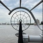
Before starting to apply the paint I did a bit of improvising with the tools to hand and marked on the waterline.
Two coats of yellow ocher where brushed on and once dry, after several attempts to get the lines right, the edges of the black strips were masked off using Tamiya’s fine masking tape.
Two coats of black paint later the tape was removed and the gun port linings were then neatened up with red ocher and a very fine brush. My concerns that I might lose the definition of the different plank patterns on the wales proved unfounded.
Finally I masked along the waterline and applied some copper paint.
Next task is to mark out the additional gun ports on the bow and come up with some kind of drilling guide for the dummy guns on the lower and middle decks.
Cheers,
Graham.
-
Charter33 got a reaction from Ryland Craze in HMS Victory by Charter33 - Caldercraft - Scale 1:72
Hi Folks,
The last of the three ’Victory material’ challenges is the construction of three ‘pedestals’ on which the finished model will be mounted. Final completion of the model is still a considerable way off – but retirement is probably going to strike before this and it makes sense to tackle the task while access to the workshop equipment is still possible. (well, that’s my excuse and I’m sticking to it…)
There are a number of unknown factors that could affect this mini project: Will it be possible to turn the metal in the first place? – I’ve come across some metals in the past that have a skin so hard it knackers the cutting tool in seconds, and what kind of finish will it be possible to achieve? Only one way to find out.
The rod as supplied…..pretty uninspiring, about four inches long and a little less than an inch in diameter.
First job is to face off the ends of the bar.
…..then skim the bar to remove the corrosion. First question answered – oh yes, it will machine. It cuts in a similar way to mild steel and is relatively soft ….
The finished billet is then cut into three blanks…
I’ve made the decision to turn the base of each column down and thread them M10 x 1.5 initially to enable each piece to be mounted on a mandrel for further machining, meaning I won’t have to hold the blank directly in the lathe’s chuck, and eventually to fix the pedestals to the wooden base.
Mounted between the mandrel and a revolving centre, each blank is machined to profile with a round nosed tool. The final finish is achieved using emery cloth followed by 600 grade ‘wet and dry’, and finally the same grade of abrasive paper lubricated with a light oil.
Just like turning legs for Windsor chairs, the first one is quite straight forward – its’ getting the others to match that provides the challenge!
Last task is machining the slot for the keel to fit into, using a universal milling machine fitted with a 4mm slotting bit. The final slot was 6mm wide. The pedestals have been previously been drilled on the lathe to take the 1/8th” silver steel rods that will extend up into the tubes set into the hull structure (see my first ‘post’).
Done and dusted….
Cheers for now,
Graham
-
 Charter33 got a reaction from etubino in HMS Victory by Charter33 - Caldercraft - Scale 1:72
Hi,
Construction of the Quarter Galleries went as per the instructions, which proved to be very accurate:
‘Time and care will be required…..’
Oh yes, and as many arms as an octopus wouldn’t go amiss! However, the effort was rewarded by the results and I must admit that that there’s much satisfaction, and a sense of relief, once the juggling of components is finished.
The upper stern counter pattern fitted easily, and to achieve the slight concave curve on the lower stern counter pattern I decided to increase its pliability by wetting it and then zapping it briefly in the microwave. I then left it, suitably supported, under a cylindrical weight to cool down and fully dry out. The photos show the result.
The next task was the middle gun deck planking. I wanted to simulate the treenails and the caulking between the planks. I’ve followed the various debates relating to how appropriate it is to have them on model of this scale but I like them and feel they are worth the effort. Little of this work will be visible once the hull is finished but it seemed like an ideal opportunity to try out different techniques in preparation for later in the build. For the caulking I went down the black thread route, running a line down each edge of the plank runs and also gluing a short length of thread to one end of each plank where it would butt up to the next.
One minor problem was the side edges of the planks which were often slightly beveled, a bit rough or marginally wider than 4mm. Fine ‘wet and dry’ glued to a piece of MDF and a sanding aid sorted this out.
The most successful method of simulating the treenails started with the marking of their positions on the ends of each plank. Another jig and a small watchmaker’s screwdriver ground to a point enabled the positions to be impressed, and these marks acted as the equivalent of centre punch marks on a piece of metal – enabling a 0.5mm PCB drill bit in a mini-drill to line up and make the hole without slipping. This drilling was done after all the planks had been glued down.
The treenails themselves were made from slithers of teak veneer. These were dipped into PVA glue, then pushed into place and cut almost flush with a pair of side cutters. The adjacent photo shows the last one going in.
Once the glue had had a chance to fully set any remaining protruding material was sliced off with a sharp chisel.
Sanding the decking risked catching the caulking thread so a smooth surface was achieved by careful use of some scrappers. After any dust had been brushed or vacuumed the surface was sealed with a coat of matt varnish after which it proved safe enough to resort to fine glass paper between each of the subsequent two coats of varnish.
The mast sleeve was fitted after the varnishing was done to make sanding the deck easier. To get the sleeve to bond to the varnished surface I resorted to rapid drying epoxy resin.
These photos show the lining of the entry ports.
The next stage, and one I’ve been looking forward to, is the second planking. Following the advice of other builds on this site (thanks to all!) I’m going to replicate the 30’ plank lengths. If my maths is right this makes a full plank 127mm long, with an overlap that works out at 2 inches. (apologies for mixing units of measurement – that’s just how my old brain works these days!)
Cheers for now,
Graham.
-
Charter33 got a reaction from CraigVT in HMS Victory by Charter33 - Caldercraft - Scale 1:72
First Planking
With the bulkheads set and the ply gunport patterns all glued in place the chamfering of the bulkheads were given a final ‘tweak’ prior to starting the planking. To help with this, and with the earlier shaping of the bulkheads, I put together a jig that held the model securely on its side. I found this helped with resisting the forces exerted when pushing the temporary pins in and could be used for the majority of the hull.
Following the advice given on this site concerning tools I invested in a pair of plank nippers. A bit of practice quickly proved what a useful piece of equipment these are, although I wouldn’t use them on the ships boats as the inside of the first planking of these is visible and the small groves the nippers leave would show. I have to date finished the first planking of the launch and some of the second planking.
The first couple of planks are laid without any need for tapering but to avoid forcing the initial planks into place I started by putting ‘stealers’ at both the bow and stern.
For the most of the planking the procedure was:
• Trim the plank end to match the stem
• Taper the top edges (with a slight undercut as well) for the first and last four or so bulkheads by anything from 1/3rd to 2/3rds of the plank’s width as determined by offering the plank up to its position. Leave plenty of overlap at the stern for later trimming
• Holding the plank in place pre-drill or bradawl (I used a map pin for this) pin holes through the plank and into a manageable number of bulkheads. (4 – 5 usually)
• Apply glue to four or five bulkheads at a time where there will be contact with the plank
• Apply glue to the matching length of the edge of plank
• Pin plank to bulkheads, and use clips between bulkheads to ensure good edge to edge contact.
Off-cuts of planking make great glue applicators!
Keep telling yourself – it’ll be fine when its sanded……..it’ll be fine when it’s sanded….
A few ‘stealers’ where required, especially at the stern, but these were no problem to cut to fit the gaps.
Sanding the hull to shape turned out to be more straight-forward than I anticipated but as it is a messy job the hull had to be transported to work for the task – you get some funny looks walking across the car park with one of these tucked under your arm! My only regret was filling blemishes with filler that was a bit darker than it could have been which tended to emphasize defects but as the whole lot gets covered with the second planking and subsequent painting it does not matter too much.
Next installment - juggling the components that make the Quarter Galleries.
Cheers for now,
Graham
-
Charter33 got a reaction from CaptnBirdseye in HMS Victory by Charter33 - Caldercraft - Scale 1:72
Hi Folks,
Yet another Victory model under way. My kit was an anniversary present (25 years!) from ‘the Boss’. I first became aware of this model through the pre-issue information in a popular monthly magazine but had to dismiss the idea due to its cost. When it was suggested as a possible gift I didn’t need asking twice.
The early stages of this build were originally shown on another website that unfortunately had to close down. I think it only fair to point this out as the rate of progress this build log will initially show will not be truly representative. Progress has been sporadic in the least. To be honest it’s taken me the best part of six years to get to where I am now (planking the upper gun deck) – life, work, other projects etc. all conspire to hold up progress.
Initial construction was fairly trouble free, with the exception of an asymmetrical bulkhead 15. Dry assembly showed where the problem was so a new one was fashioned from some scrap ply I had lying around the workshop.
The next challenge was drilling the holes in the keel for mounting the model later. I decided to insert 1/8th diameter brass tubes, with ply re-enforcement where needed, and to use steel pins to locate it onto a display base (one day!) To do this accurately it made a drilling jig based on a traditional design I use at work.
Chamfering the bulkheads was one task I was not looking forward to, and it was at this point I discovered the value of websites such as this. Black felt pen lines on the back edge of the bulkheads that needed shaping ensured that I did not go beyond the profile.
Concerned about how the lower ply gunport patterns would bend around the bow I cut a block of timber to fabricate a press forming tool. A card template was cut to match the shape of the bow and this was then transferred to the top of the block and band-sawed.
The double cut design allowed both sides to be shaped at once. The ply was soaked for an hour, sandwiched between the blocks and left clamped for a day. The photo shows the result of a test run using waste from the gunport ply sheets.
The strips were still slightly damp and pliable when removed from the former 24 hours later. With hind sight this was definitely ‘over kill’ and I probably wouldn’t resort to this method again, but it did the job!
Details of my experiences with the first planking will follow……..
Cheers for now,
Charter33.
-
 Charter33 got a reaction from goetzi73 in HMS Victory by Charter33 - Caldercraft - Scale 1:72
Thanks for dropping by Marc, here is yet another jig!
Decision made – I’m going to stick with the approach given in the manual and work up from the keel – thanks Steve for the ‘nudge’ that finally swayed me.
After several sessions I have now fitted about 10% of the copper plates. It was always going to be a long haul, but so far it’s been fairly straight forward and surprisingly therapeutic!
One aspect that has been giving me food for thought was how to deal with the keel. I wanted to cover the bottom of it with plates folded evenly over the edges. With the keel 5 mm thick and the plates 6 mm wide this means a ‘return’ of 0.5 mm on the side of each plate. Early attempts with flat pliers and then brass soft jaws in a bench vice failed miserably ……
With approximately 60 plates needing to be shaped some kind of simple former was going to be required. This is what I came up with:
The main body consists of two 60 mm lengths of 5 mm square mild steel bar. The lower part has a shallow recess equal to the length of a copper plate filed into it while the upper bar has two grooves filed in with a ‘three square’ needle file to provide clearance for the raised rivet heads that run across the ends of the plates. I couldn’t find any small diameter socket headed machine screws to apply the clamping pressure in the workshop so resorted to cutting M3 x .5 threads on the pins of a couple of plated brass ‘push buttons’ from old 1970’s telephones that were rattling around at the back of a cupboard – knew they’d come in useful one day ….. Clearance holes in the top bar and suitably threaded holes in the lower bar finish the former.
The plate is put in place, but first checked to ensure that the rows of ‘rivets’ on the side are equally spaced from the edges – this sometimes varies considerably.
After clamping the protruding edges are pushed by thumb in the right direction and then a piece of softwood dowel is rolled along the edge to complete the bend.
... and the job's a goodun...
I hope this will be of some use to other builders.
Cheers,
Graham.
-
Charter33 reacted to Torbogdan in Fokker DR 1 by Torbogdan - FINISHED
Firewall in place and dry fitting engine. I have more pictures but have trouble uploading them. Anyway the engine is done with all washing and drybrushing and "aging". Turned out nice. In this picture it is not done, I finished it after dry fitting it here. I have also started to paint all the little instruments that goes into the cockpit area. I do deviate a bit from the instructions but I´m waiting for the book I´ve ordered. The instructions are ok in the kit but I sometimes a bit fuzzy so to speak. I hope the book will give some nice pictures or drawings where all the wires go and how all the "little things and instruments" are mounted and where. So while waiting I´m doing all the small stuff.
I hade to improvise the cables running from the engine, it was not enough wire in the kit so I used some scrounged up copper wire, it will be painted of course. I´ll do that towards the end when it is in its correct position.
I have also started on the propeller. I have sanded it to its general shape so to speak. But same here, waiting for the book and hope for some nice pictures on its final shape. I feel it is much easier to remove wood from the prop than replacing it, so I´m careful and only want to do the final sanding when I´m sure about its shape.
-
Charter33 reacted to dj.bobo in RNLB Ruby & Arthur Reed 2 by dj.bobo - FINISHED
Good evening for everyone. Things go slower due to small pieces.
For now turnbaker tensioner.
A beautiful evening still I want you.
Adrian
-
Charter33 reacted to michel saunier in SOLEIL ROYAL 1669 by michel saunier
In fact I wanted, challenged by my MMB forum friends, to create a quet that approximates that of the SR. These parquet floors are called "Versailles". So I created a block of alternate wood slats and then grinded into the milling machine, in several layers to get what you see. Then sawing of lamellae of this block, finishing each one (thickness 5 / 0th of mm), assembly and gluing on a thick paper to the dimensions of the piece, finally the assembly glued on the bridge.
I am quite satisfied with the result that, alas, we will not see any more because the aft fellow comes to hide everything.
-
Charter33 reacted to Steve 12345 in HMS Bounty by Steve 12345 - FINISHED - Billing Boats - 1:50
Hello gentlemen and Derek
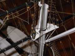
with the mast fighting tops and crosstrees fitted I have applied paint and now started work on the yard arms ,both the masts and yards will be rigged with as many blocks and fittings as possible before I can place them and commence standing rigging.
with the masts set in I can take sizes for a display cabinet and work on it at the same time when I fancy a break and some workshop time.
I also took the opportunity to take out the Victory and show the two in comparison ,the victory is 1/78 scale and the Bounty 1/50
-
Charter33 reacted to michel saunier in SOLEIL ROYAL 1669 by michel saunier
I present here the latest photos of my Royal Sun. It is not finished and if it interests you I would put you following as work progresses.
Excuse me but not speaking English I use the Google translator
-
Charter33 reacted to ken3335 in Royal William by ken3335 - FINISHED - Euromodel - Scale 1:72
Hello again. Thanks for your likes and comments on my last post.
Nothing to report on R.W. today, just getting my mind around preparations for the second planking.
My modelling experience is mainly building and flying model aircraft. For numerous reasons I gave up just over fifteen years ago when I was probably on top of my game. When I started to build boats about five years ago I found that the skills required were quite different, aircraft being more technical and boats being much finer detailed but both require a certain dedication, ingenuity and quite a bit of patience. Just a thought!
This is not a boat post but as everyone loves looking at pictures here's a few of my models from that time. They were scratch built were 1/4 scale and flew very successfully, even at air shows.
Ken
-
Charter33 got a reaction from CaptnBirdseye in HMS Victory by Charter33 - Caldercraft - Scale 1:72
Hi,
Thanks once again for the generous comments and ‘likes’ – much appreciated as always. Michael - the Gloucester Javelin has a special significance. My dad worked on their electronic systems when he was in the RAF and I have clear memories of being taken to watch pilots practicing circuits and landings in them - this is probably responsible in no small way for sparking a lifetimes interest in aviation.
Meanwhile back in the marine world ,,,,, I need to start this post with an apology! Throughout my career in teaching I have always been an advocate and proponent of the old adages ‘measure twice, cut once’ and ‘never assume …’ In my previous post I referred to the spigots on the dummy cannons being under size. I have since found that this applied only to the 32 pdr cannons. Spigots on the 24 pdr cannons were bang on 2 mm. Consequently the holes in their deck have had to be re-drilled (No. series 44). At least they were under and not oversize.
Progress with my Victory has been a bit slow over the last couple of weeks. I have just returned to work after an absence of over a year, all be it now on a part time basis, and to be frank I have returned home most days well and truly knackered. It’s been a long and at times difficult journey but the end is at last in sight. Modelling activity recently has inevitably been a case of quietly browsing this site (always time well spent).
I have now started to add the copper plates to the hull. A strip of micro-ply as wide as the plates and marked with divisions equal to their length was pinned to the hull to help gauge the fall of the ‘part’ plates at the ends of the initial runs and to mark the width of the first line.
The plates are being attached with a couple of drops of c.a. glue applied before being pressed into place. I am still thinking about whether to follow the method described in the manual ie. working up from the keel, or to plate some straight runs from the water line down as well.
Thirty one plates now in place, so just 2569 to go …..
Onward and upwards!
Cheers for now,
Graham.
-
Charter33 got a reaction from leginseel in HMS Victory by Charter33 - Caldercraft - Scale 1:72
Hi,
Thanks once again for the generous comments and ‘likes’ – much appreciated as always. Michael - the Gloucester Javelin has a special significance. My dad worked on their electronic systems when he was in the RAF and I have clear memories of being taken to watch pilots practicing circuits and landings in them - this is probably responsible in no small way for sparking a lifetimes interest in aviation.
Meanwhile back in the marine world ,,,,, I need to start this post with an apology! Throughout my career in teaching I have always been an advocate and proponent of the old adages ‘measure twice, cut once’ and ‘never assume …’ In my previous post I referred to the spigots on the dummy cannons being under size. I have since found that this applied only to the 32 pdr cannons. Spigots on the 24 pdr cannons were bang on 2 mm. Consequently the holes in their deck have had to be re-drilled (No. series 44). At least they were under and not oversize.
Progress with my Victory has been a bit slow over the last couple of weeks. I have just returned to work after an absence of over a year, all be it now on a part time basis, and to be frank I have returned home most days well and truly knackered. It’s been a long and at times difficult journey but the end is at last in sight. Modelling activity recently has inevitably been a case of quietly browsing this site (always time well spent).
I have now started to add the copper plates to the hull. A strip of micro-ply as wide as the plates and marked with divisions equal to their length was pinned to the hull to help gauge the fall of the ‘part’ plates at the ends of the initial runs and to mark the width of the first line.
The plates are being attached with a couple of drops of c.a. glue applied before being pressed into place. I am still thinking about whether to follow the method described in the manual ie. working up from the keel, or to plate some straight runs from the water line down as well.
Thirty one plates now in place, so just 2569 to go …..
Onward and upwards!
Cheers for now,
Graham.
-
Charter33 reacted to Ainars Apalais in H.M.S. Triton Cross Section by Ainars Apalais - 1:48
Hi.
I add a little progress from my model.
I glued the first top plank to hold together all frames. And cuts off all frames in the right-size.
And only then start sanding inside of hull.
Step by step I stars planking.
First planks I made a slightly curved. To keep straight part in bottom of inside hull. As well pre drill holes in keelson for hold pillar.
Next I made a couple of clams for planking. To make future work easier.
It works pretty well.
Cut out limber board in right shape. And cut it by small parts.
Then folded again all together and drill holes between.
By individual pieces I glued it In place. I leave only place for pump room.
It's all for the moment.
I hope so will have more free time to keep going.:)
Ainars
-
Charter33 reacted to Shipyard sid in HMS Victory by michael101 - Caldercraft - Scale 1:72
Hello Michael
It's me again !! You have four gunport patterns to fit before you start any strip planking. You should find the fairing for those pretty easy, but be careful at the tight bend of the bow, the pattern will need to be soaked for a while at the bow end. When you look at the bulkheads that then need fairing it's only the first five that need a lot of attention, and the fairing should be really well done, so take your time. You must make sure the strip you are using to test your fairing lays flat on all the faired faces of the curvature, across all the bulkheads. The curve around the bow is very tight, and if the strips do not lay flat on the faired face of the bulkhead, the strips will buckle or even break. The fairing of all the other bulkheads is not hard at all. Once you get the four gunport patterns fitted you are off and running with fitting of the strips. No twisting of the strips !!!!!!!!!!! Let them run naturally and infil the gaps with strakes. I am sure you will have no problem. Off you go then !!! Good luck 🌝🌝 we are all rooting for you.
best regards. DAVID