Some Idea
-
Posts
1,152 -
Joined
-
Last visited
Content Type
Profiles
Forums
Gallery
Events
Everything posted by Some Idea
-
 If you want a nice polished finish close grained hard wood is probably the best for this. Personally if I want a really polished finish I work my way down the sand paper grades to 400 and then finish with a grey scotch pad. It's the scotch pad that gives the polished finish but is not a good surface to glue onto. If you want a mega polished finish Foredom sell pink coloured sanding discs which are 1600 grit. They really make wood shine but can only do small areas
 -
Good to see you back - those little Veritas squares are great I use mine all of the time
-
L'Amarante by marsalv - 1:36 - POF
Some Idea replied to marsalv's topic in - Build logs for subjects built 1501 - 1750
Precise woodwork and lovely brass work; what's not to like! here It will be nice to see the stove sat on the area you have prepared too. -
I think you're right I can just imagine them smashing holes through for a quick build! Hi mate - yes it does rotate within its stocks. Hi Chris the actual hinging part is 3mm wide - 1mm per part. The hinge pin is 1mm.
-
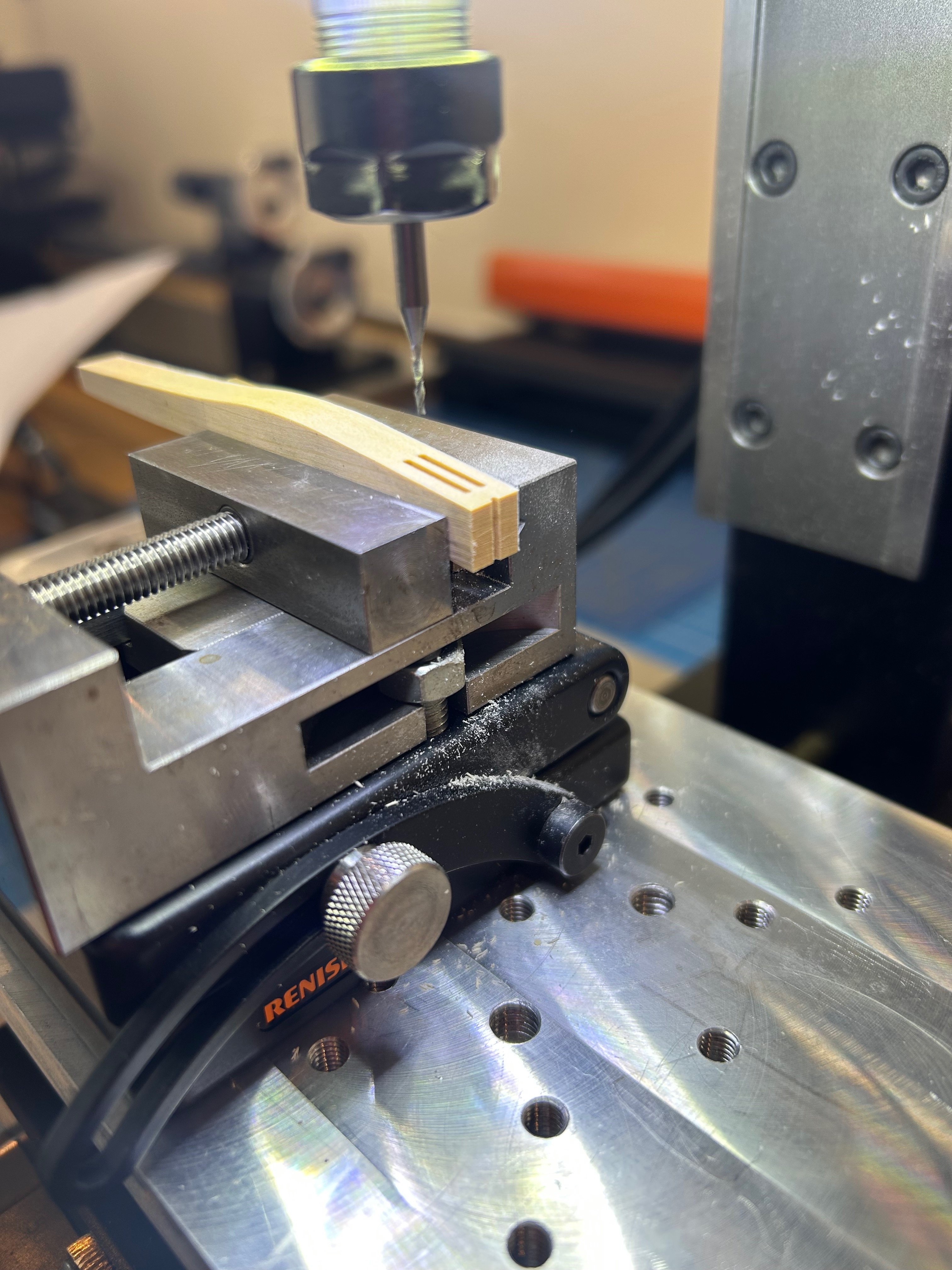
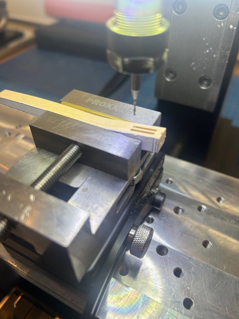
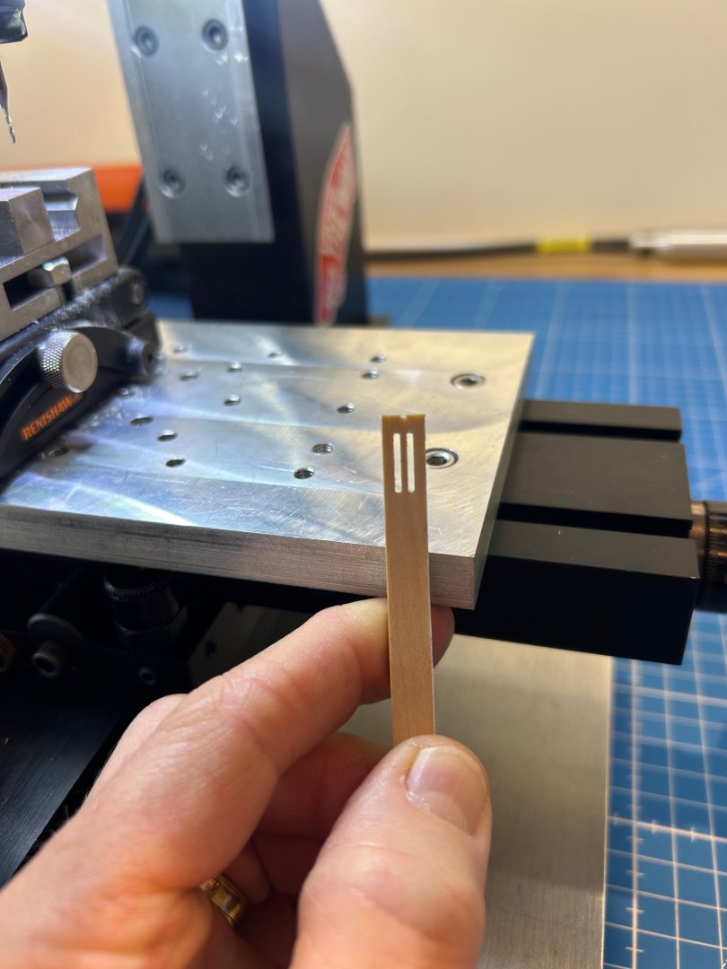
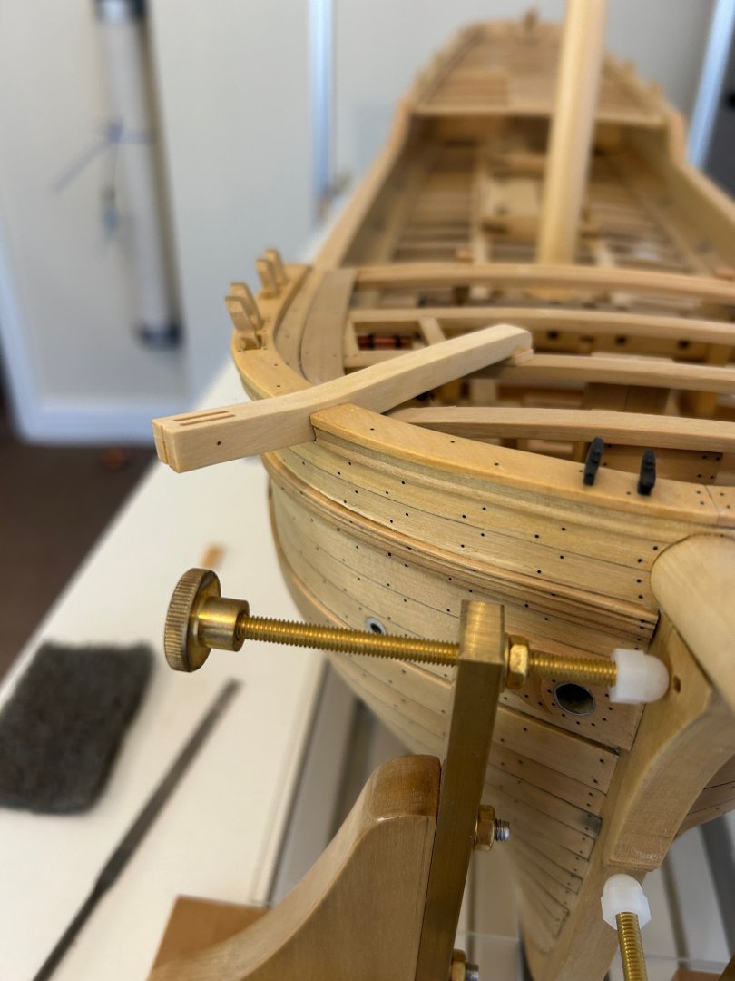
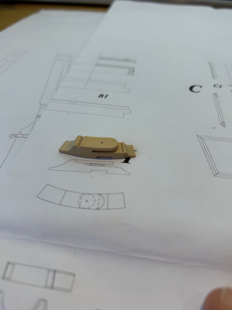
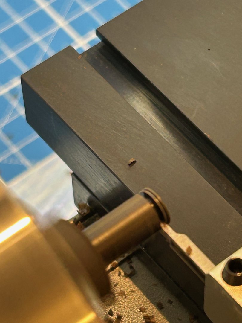
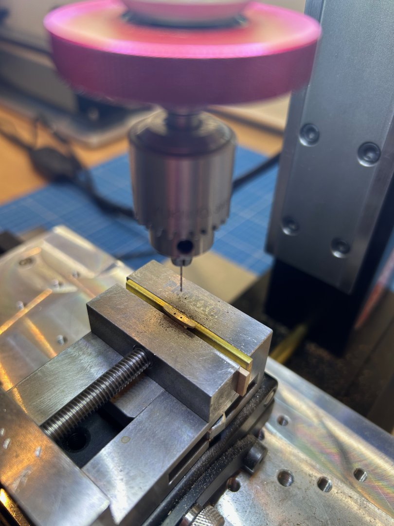
Some more work done and this time it's the windlass pawl which is a very simple mechanism on this ship. Firstly I made the hinge out of brass but I forgot to take any photos of the actual process. It was quite simple really as all I did was to silver solder some 2mm tube onto some 1mm plate and then put it in the milling machine. The only issue I could foresee was that the holding point in the vice was very small so only light cuts could be taken. I also had the machine running at 10k rpm which lessoned the vibration during cutting. Why is it I always drill one hole out of line? I wouldn't mind but I centre punched it too........ The pawl has a wooden piece that it is recessed into - its this wooden part which locks into the windlass. Finally the completed installation and I'm glad to say that it did fit into the windlass My next job will be the hatch surround on the forecastle deck and then the pin rail. Thanks for all of the comments, likes and help Mark


-
Andreas that really is such precise lovely work - congratulations so far.
-
What lovely carpentry and all by hand too - you certainly have skills with hand tools.
- 32 replies
-
- 4
-

-

-
- NRG Capstan
- NRG
- (and 1 more)
-
Gregory and druxey - thanks both for the information. Your ideas should definitely improve my efforts so I'll give them a go.
-
Thanks very much Keith
-
Hi Everyone I have a confession - I struggle making decent ring bolts 😒 I was given great advice by druxey on how to make the actual ring or triangle and I can do this part. Making these shapes is ok for me now and I silver solder them together and end up with very nice rings and triangles. However it's the part the ring or triangle is attached to that goes into the deck that I am struggling with. Currently I'm making eye bolts to fit them too but they never seem to look that good when assembled. They always come out in different sizes and it's so fiddly trying to fit the parts together. So help me out and let me know your techniques as I really need to improve this part of my modelling. As a general rule I am currently using 0.5mm and 0.8mm brass to make these fittings if this helps. Looking forward to hearing from the forum - Mark
-
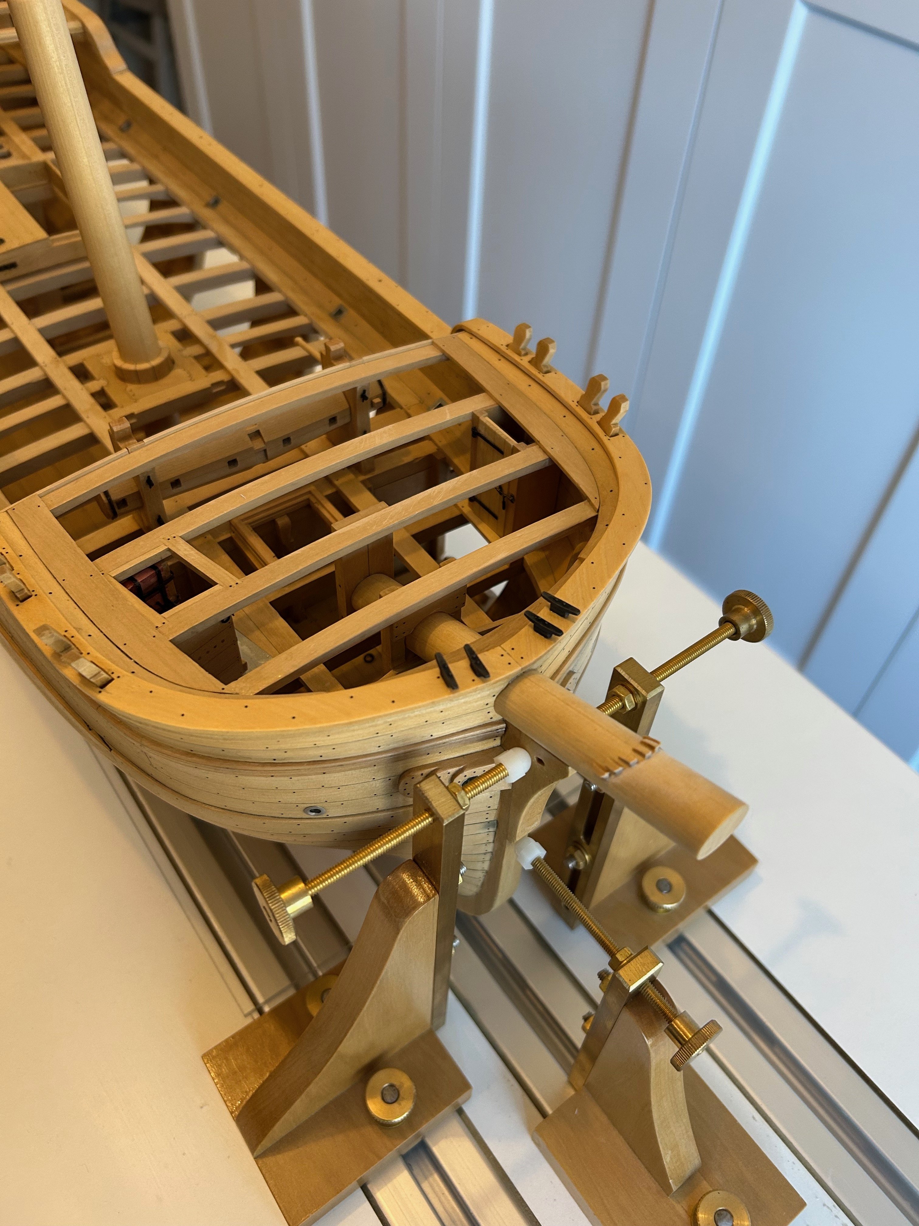
Thanks Steve - you are right about emotional preparing yourself. Honestly I went to make the first cuts twice and didn't before I finally just got on with the job. I just kept on thinking that if I didn't make the cuts square and tight it would ruin the look of the bow. Next time will be easier though as I now know that I can do it. Thanks Brad I actually really enjoy documenting this build and I'll probably do the same with my next build too. Hi Greg thanks very much and yes you are correct; part of my apprenticeship was tool making at a time when most parts had to be made rather than bought. My "operating table" as my family call it is fantastic. I'm really looking forward to my next build when I can raise frames on it which is when I can start making additional helpful attachments. I've got quite a few ideas in my mind which hopefully will work. Thanks so much thats a very nice thing to say
-
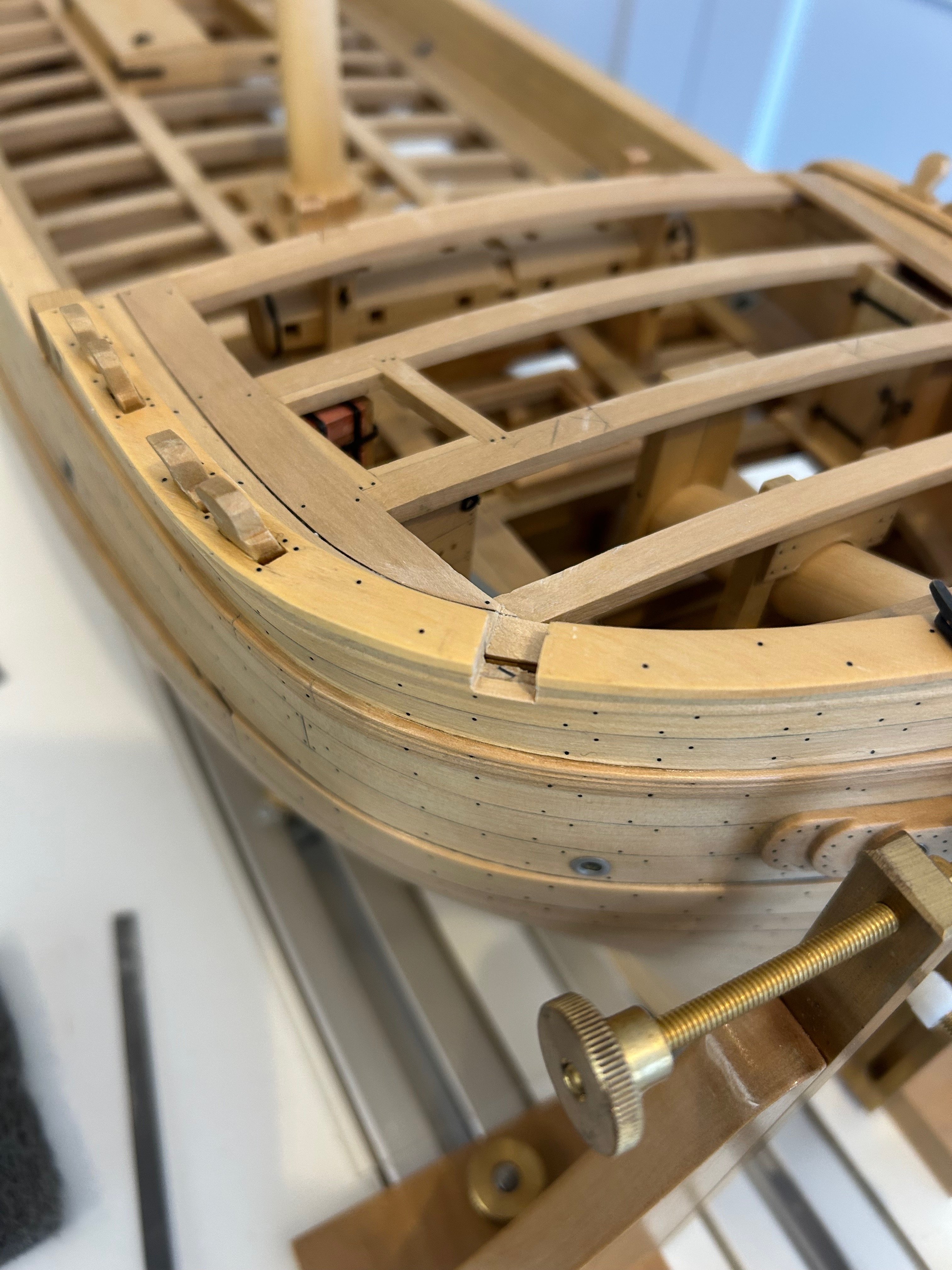
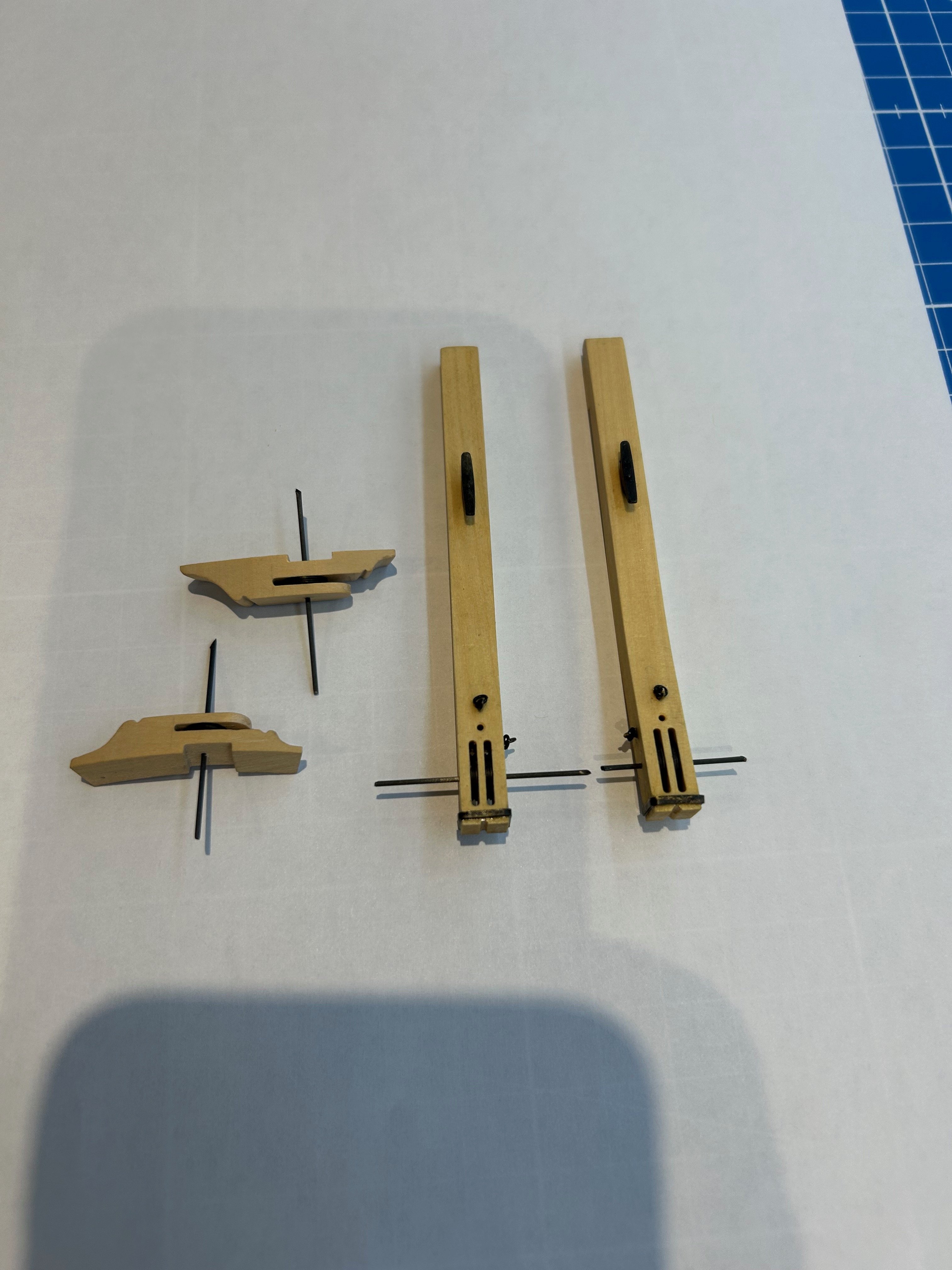
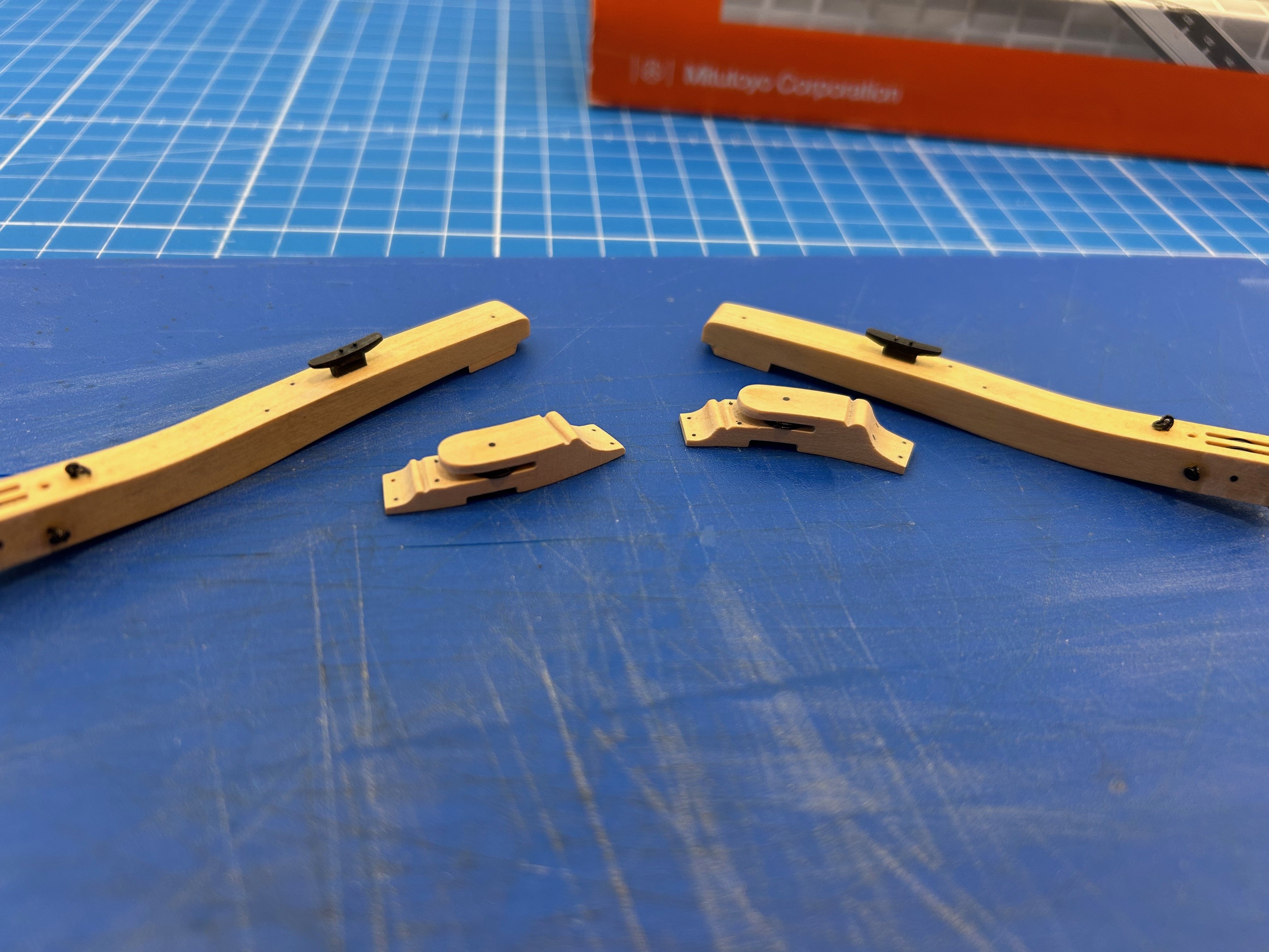
Another update on Le Rochefort and this time it's the catheads and snatch sheave blocks. Making the catheads I found to be relatively straightforward; the only issue I had was that my end mill was too short to complete the sheave slots from one side. It was just one of those times when you have to trust your datums and turn the piece over to complete the cuts. Now fitting the catheads is not easy at all. You need a bit of bottle to cut through your newly made gunwale, moulding and waterway. I just took my time and removed little pieces at a time. Next I made the snatch sheave blocks - these are really nice to make as they really make you plan the cutting order to still be able to hang onto them. Next were the sheaves and I have had this piece of ebony wood knocking around in my drawer for ages. So I thought it would be very nice to make them out of that. To finish all of the pieces off I made the ring bolts, iron ring and fitted the sheaves in place. And finally I fitted all of the parts to the ship Next up I'm going to finish off the windlass by making the locking pawl. Cheers Mark


-
You're not wrong I think you're looking at about 6 hours work for 8 cleats! But a challenge is a challenge
-
Funnily enough I wasn't sure about whether I would make all of the parts or not as some parts are so readily available on line. I didn't make the bricks in the stove but the more I build the more important it is that I do make as many parts as possible. I'm sure that many other builders feel the same as the satisfaction is just so nice when the part you make just fits the ship.
-
kit review 1:48 La Renommée 1744 - CAF Model
Some Idea replied to James H's topic in REVIEWS: Model kits
I really like CAF models - there must be so many builders who do not have the space or cash to buy all of the tools for a scratch build. But they would love to make one so this must be the very next best thing. Some of the finished ships I've seen look incredible and I like the way they can be bought in chapters too- 20 replies
-
- 3
-
-
- cafmodel
- la renommee
- (and 1 more)
-
Hi Kevin Its so great to see you back building buddy - looking forward to your updates and I also hope that you are ok Mark
- 322 replies
-
- 4
-
-
- enterprise
- caf
- (and 1 more)
-
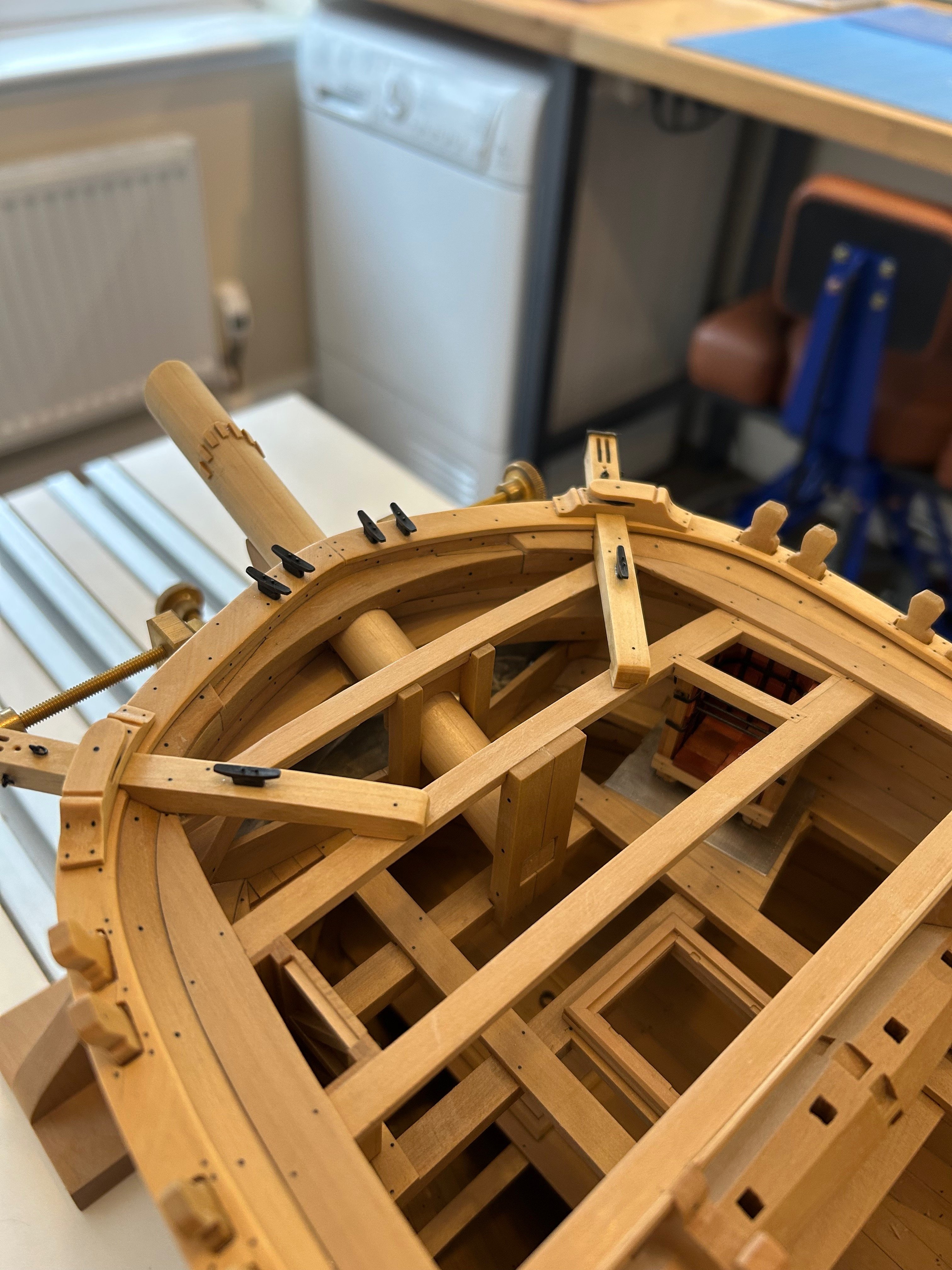
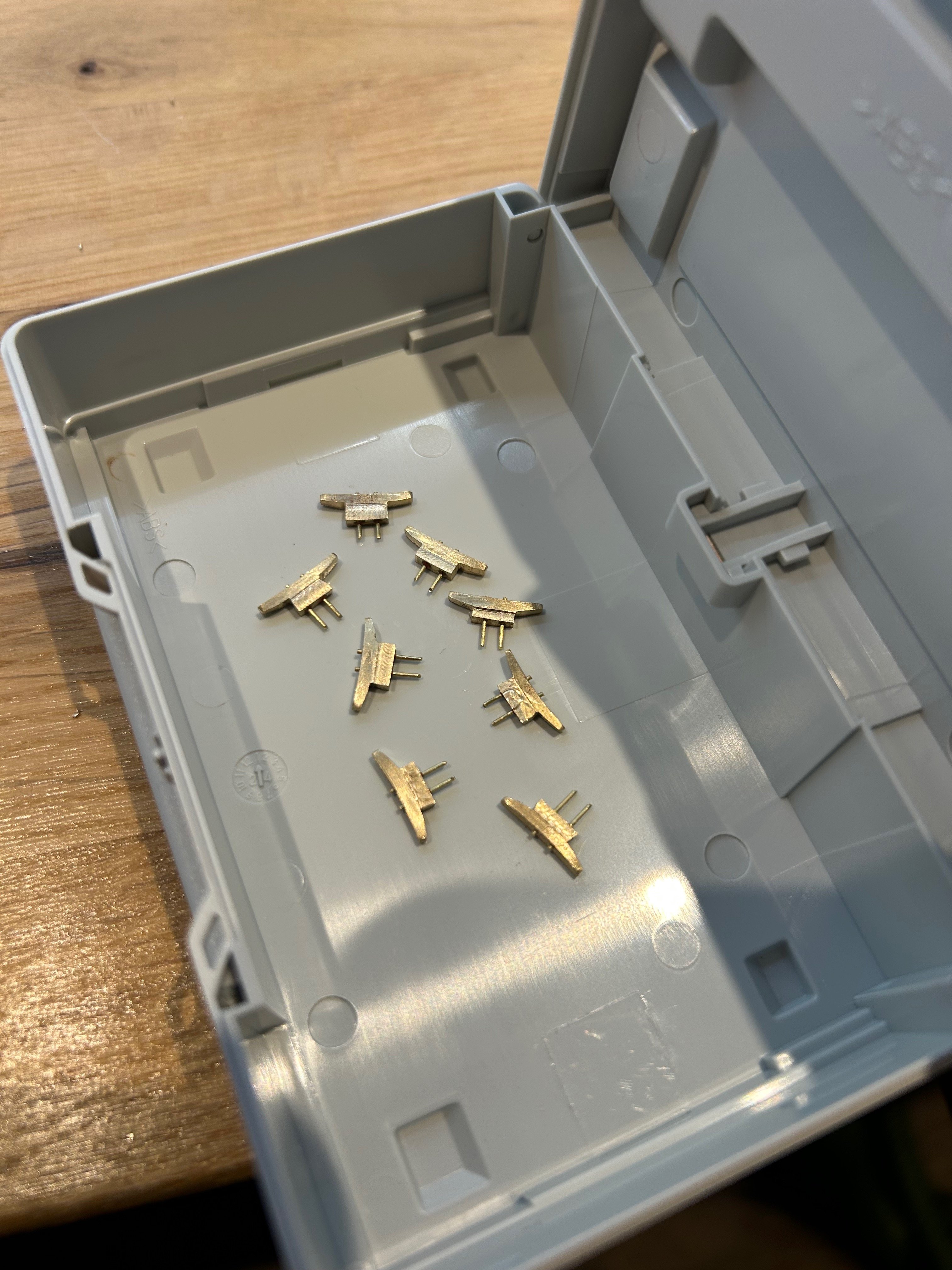
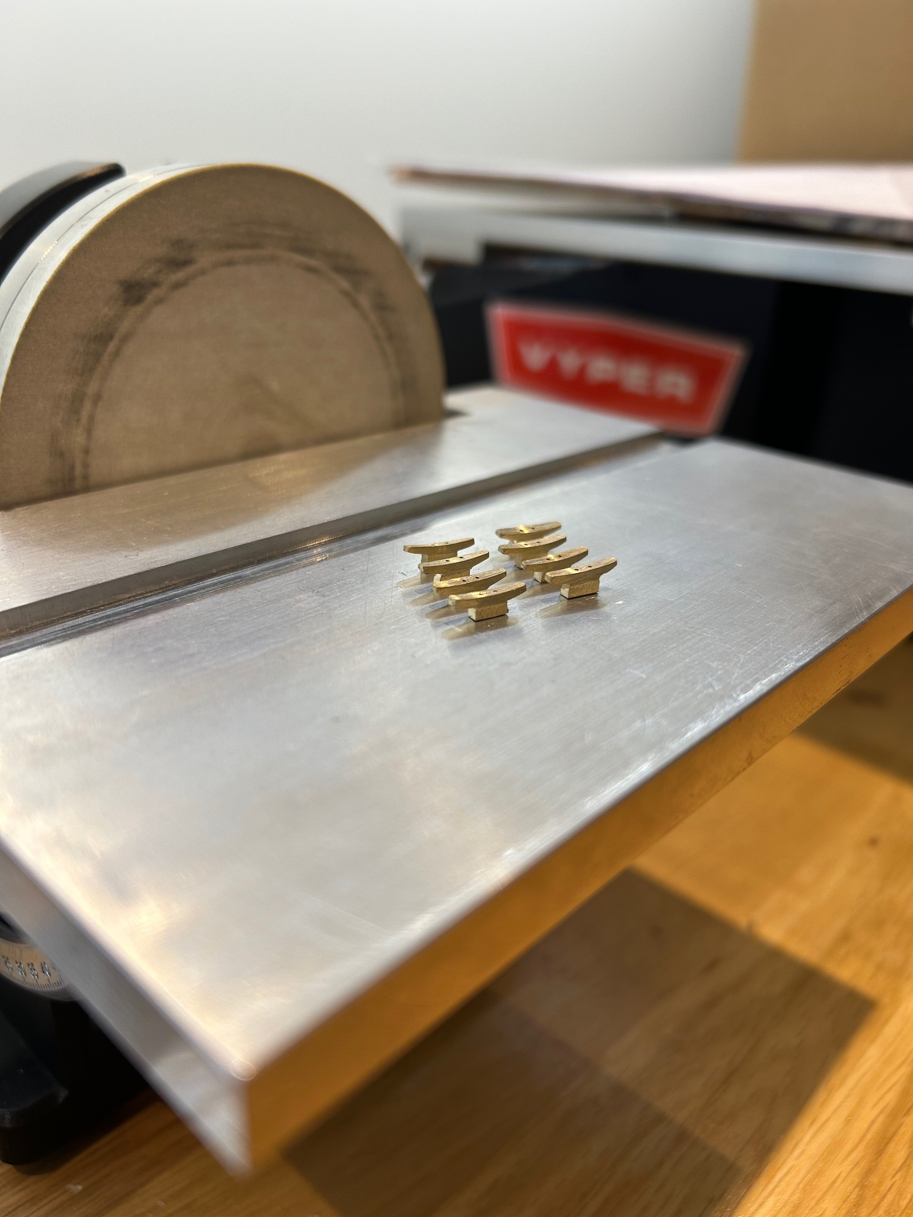
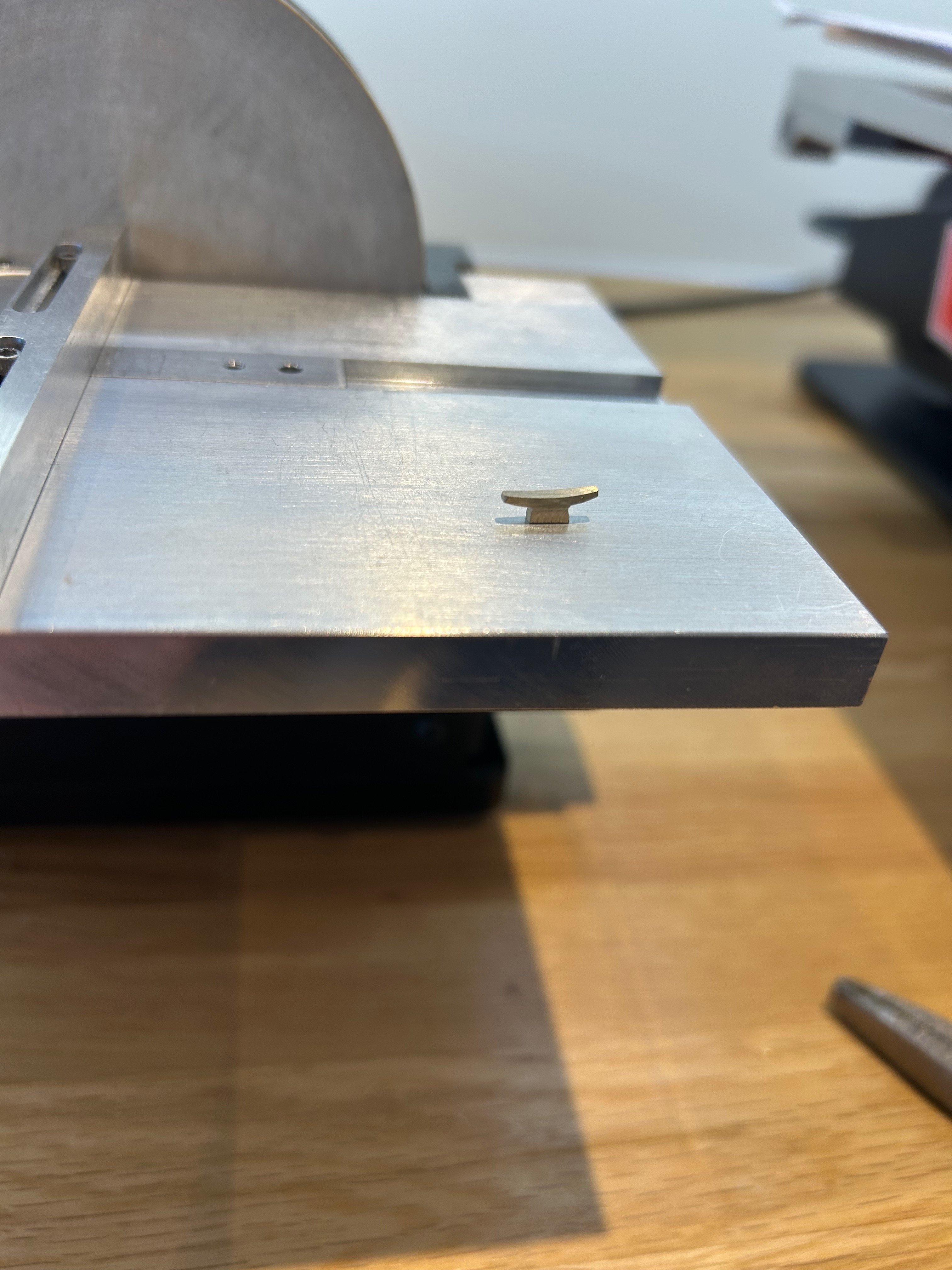
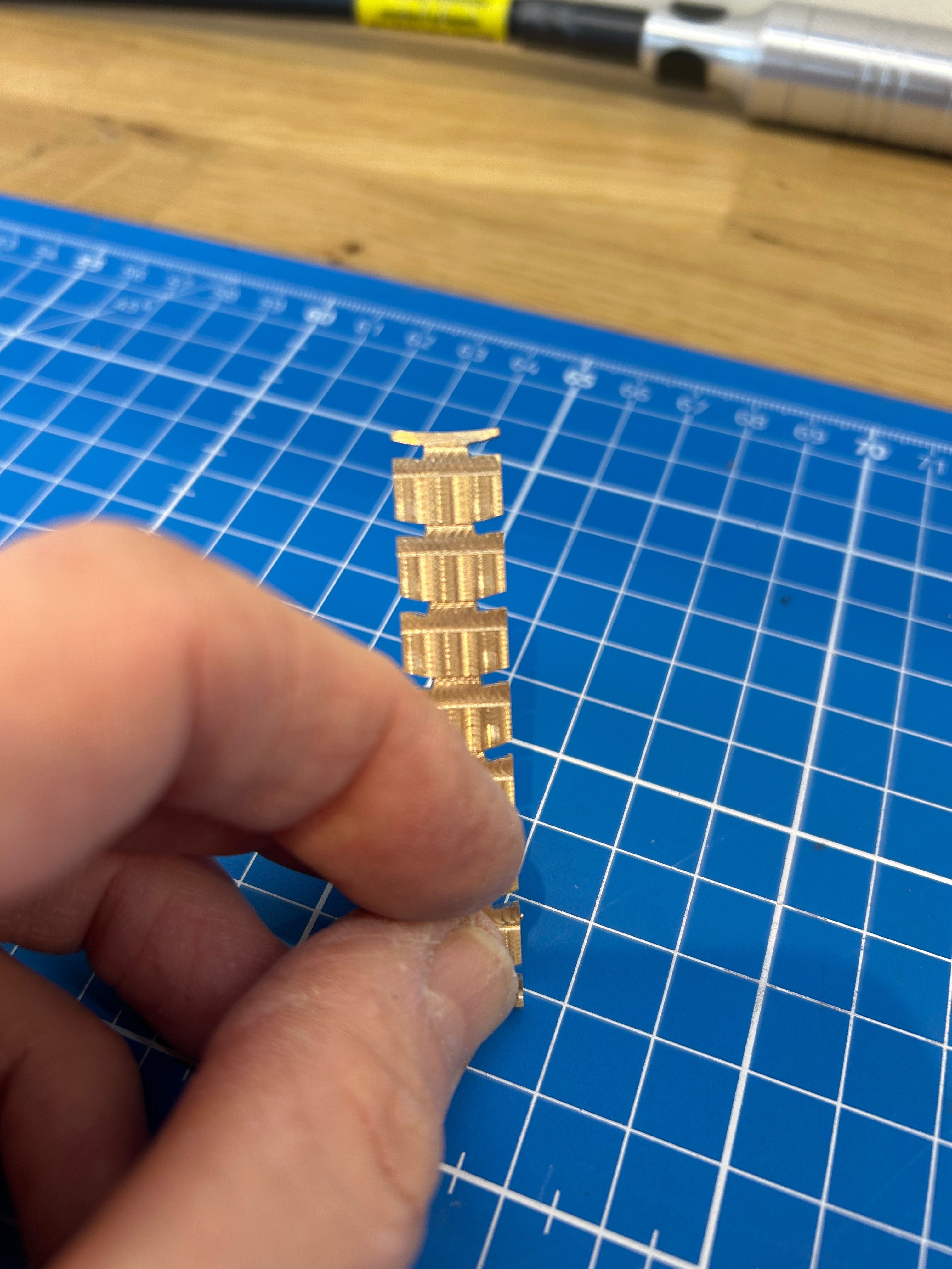
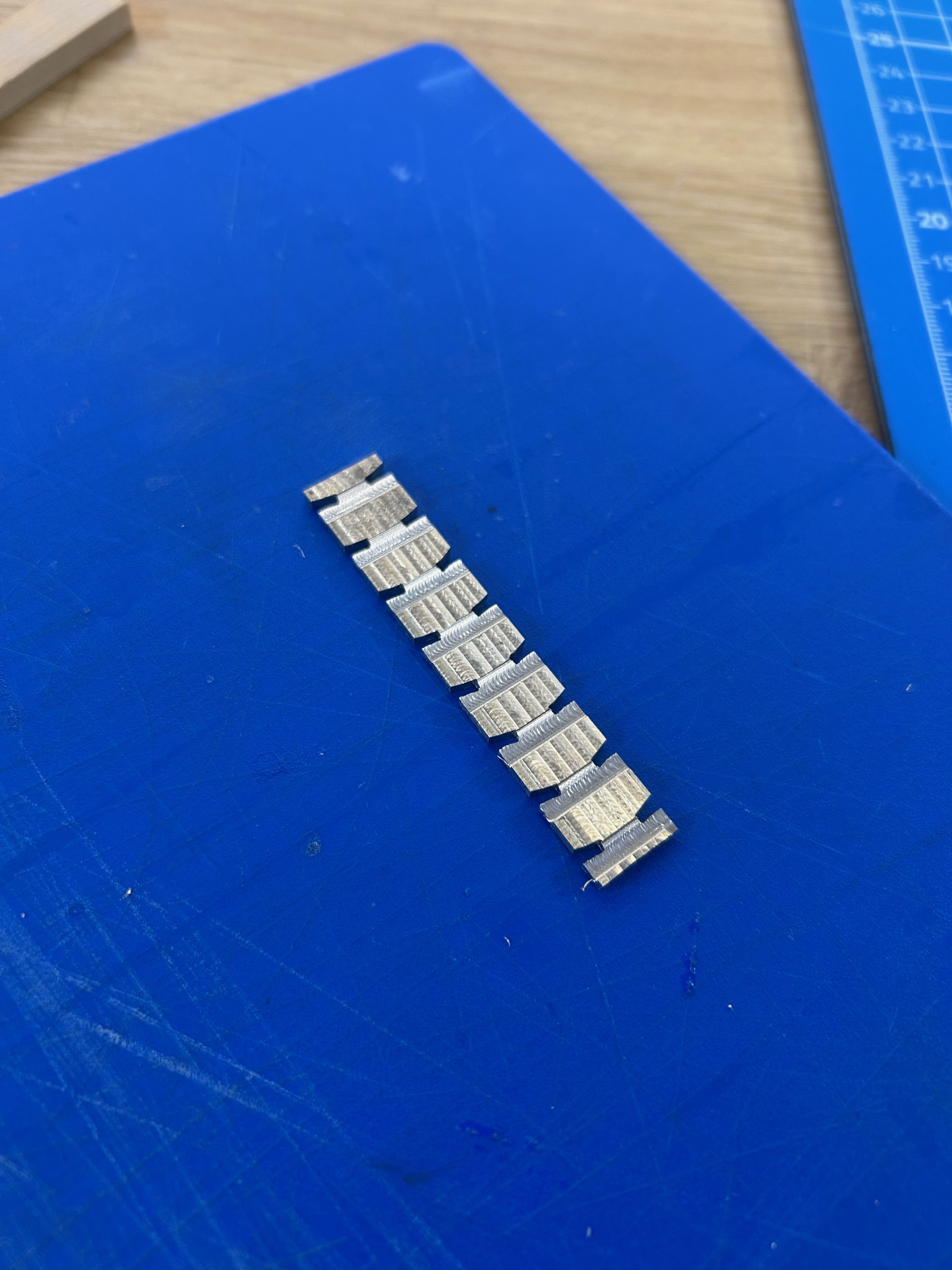
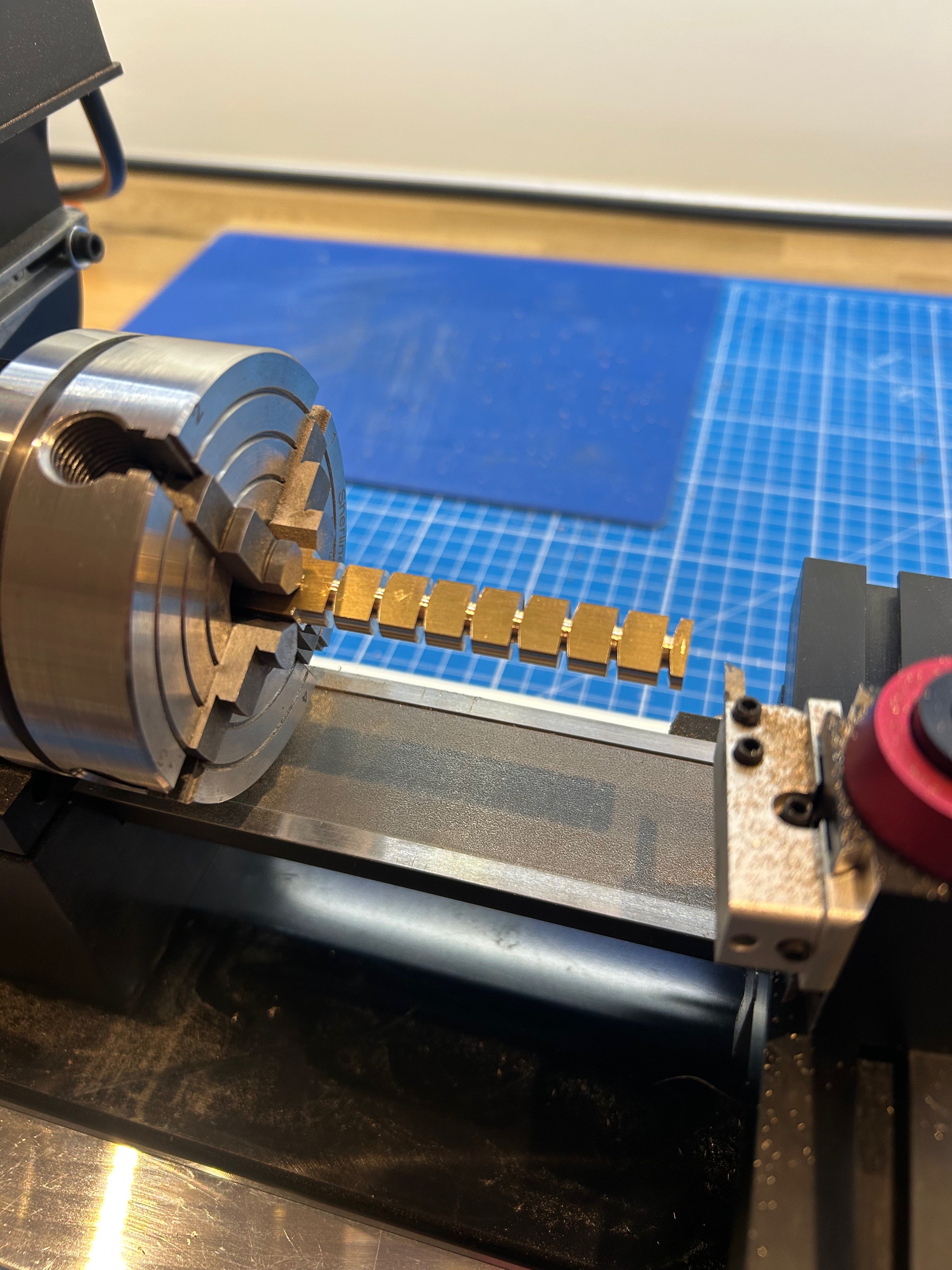
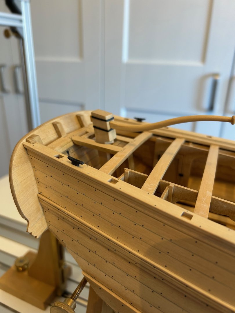
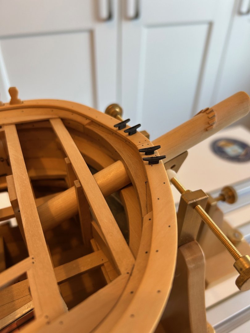
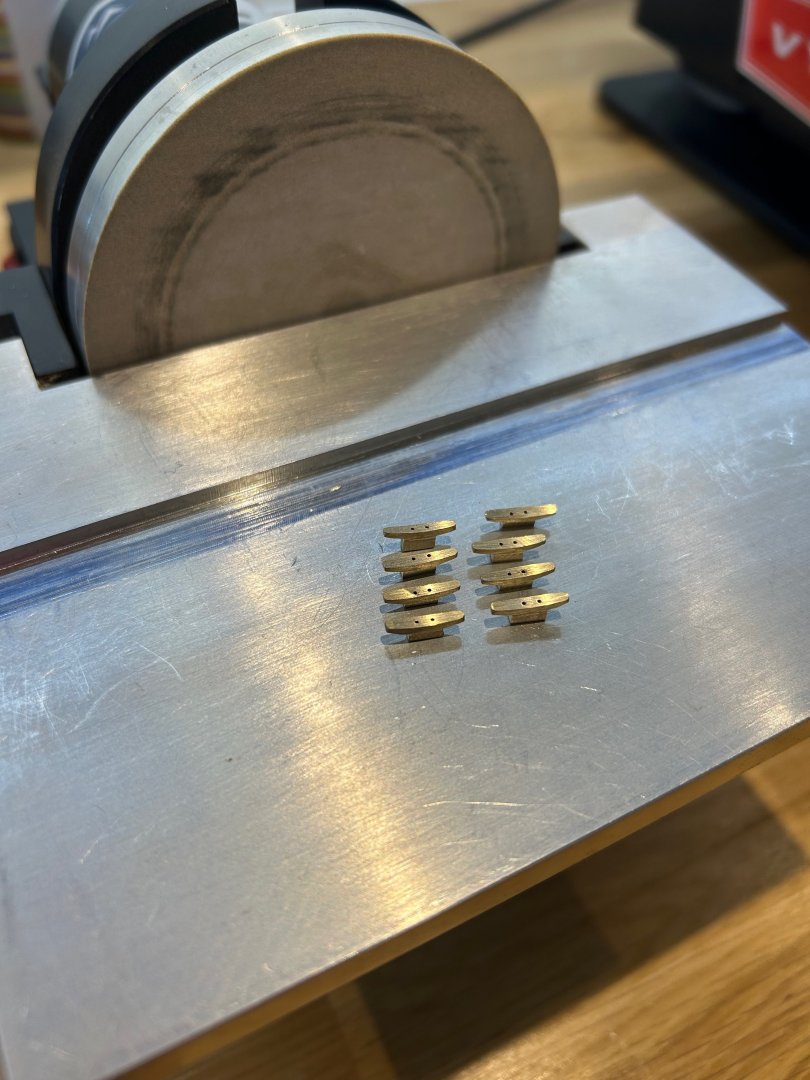
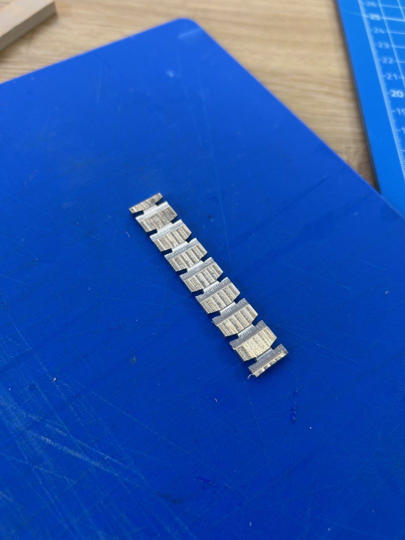
Starting on the catheads I could see that they both have a cleat on the top of them and there are 6 others across the gunwale. So I thought let's start with them as I've never made cleats before and I can make them all in one go. For some reason I thought it would be good to make them out of brass and blacken them as in my mind they will make a nice contrast to the wood. So without knowing what I'm doing I started with a piece of flat brass bar which was 3 times thicker than required at 6mm. I used this piece simply because I'm still waiting on a chuck for the tail stock so I couldn't centre drill a hole for the live centre. I needed some strength in the material due to the amount of metal sticking out of the chuck. So once again I used an independent 4 jaw chuck to hold the brass and using the drawings I roughed out 8 cleats leaving plenty of material between each one. I then placed this on the mill and cut the piece down to its correct width of 2mm. The rough finish is because I held it down on the tooling plate with double sided tape. I also thinned the bottom of each cleat to make the separation from their tops. Next was to cut the familiar curved top edge and then cut the cleat off using a hacksaw. Then I could finish the basic shape by hand using a file. After that was done I drilled 2 - 0.5mm holes in each cleat and put some 0.5mm brass rod through. This acts as both the fixing heads and location dowels onto the ship. The rods were fixed in place using a small drop of Loctite 271 rather than soldering. Finally I rounded everything off as best I could and chemically blackened them. I fitted the 4 cleats onto the bow gunwale and 2 onto the stern as per the drawings. This leaves me 2 left for the catheads. All in all I'm pretty pleased the way these have turned out as I made up the cutting sequences on the go. I would like to thank everyone for the advice, corrections, encouragement and the downright lovely comments. Catheads next Cheers Mark


-
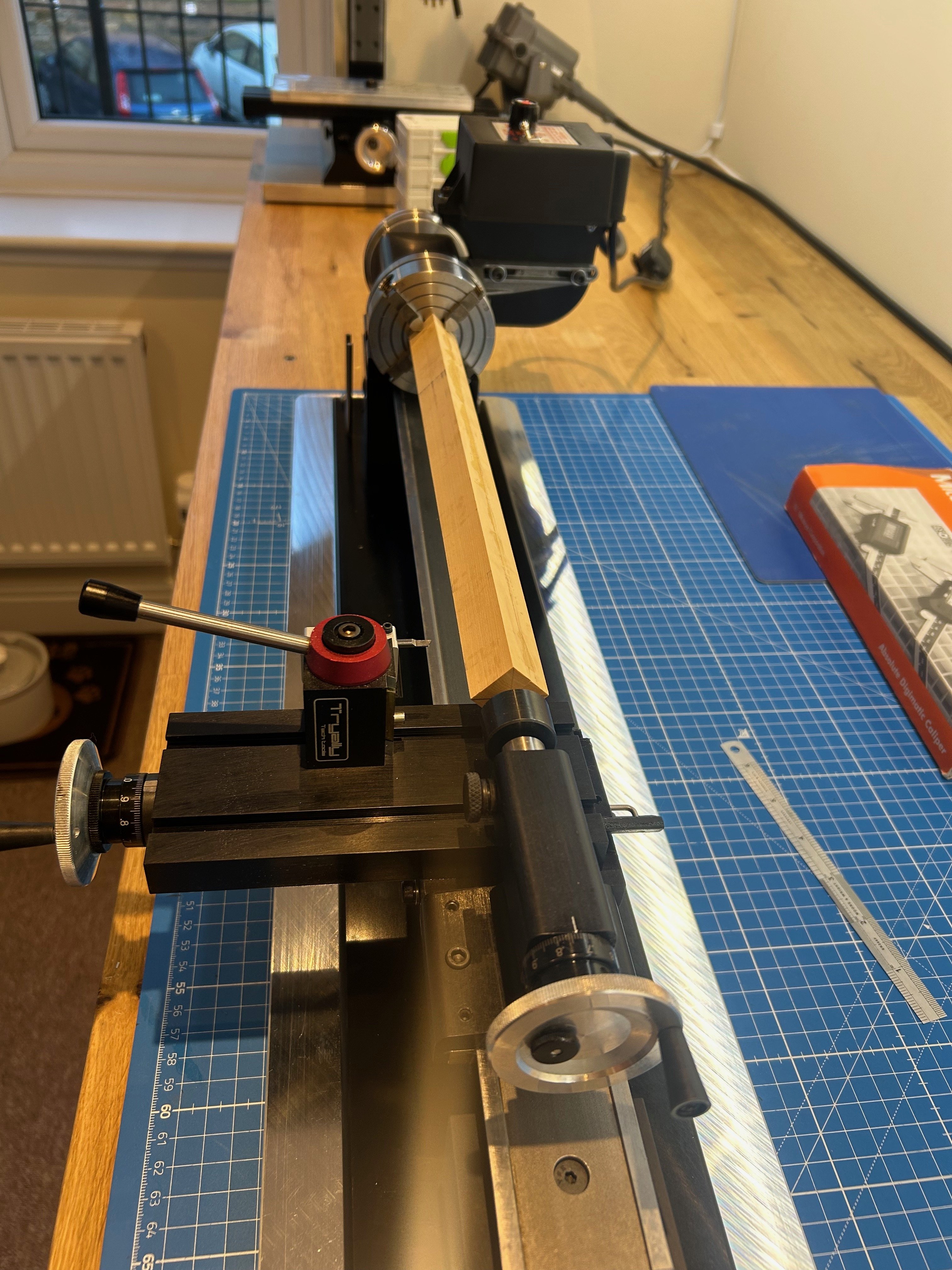
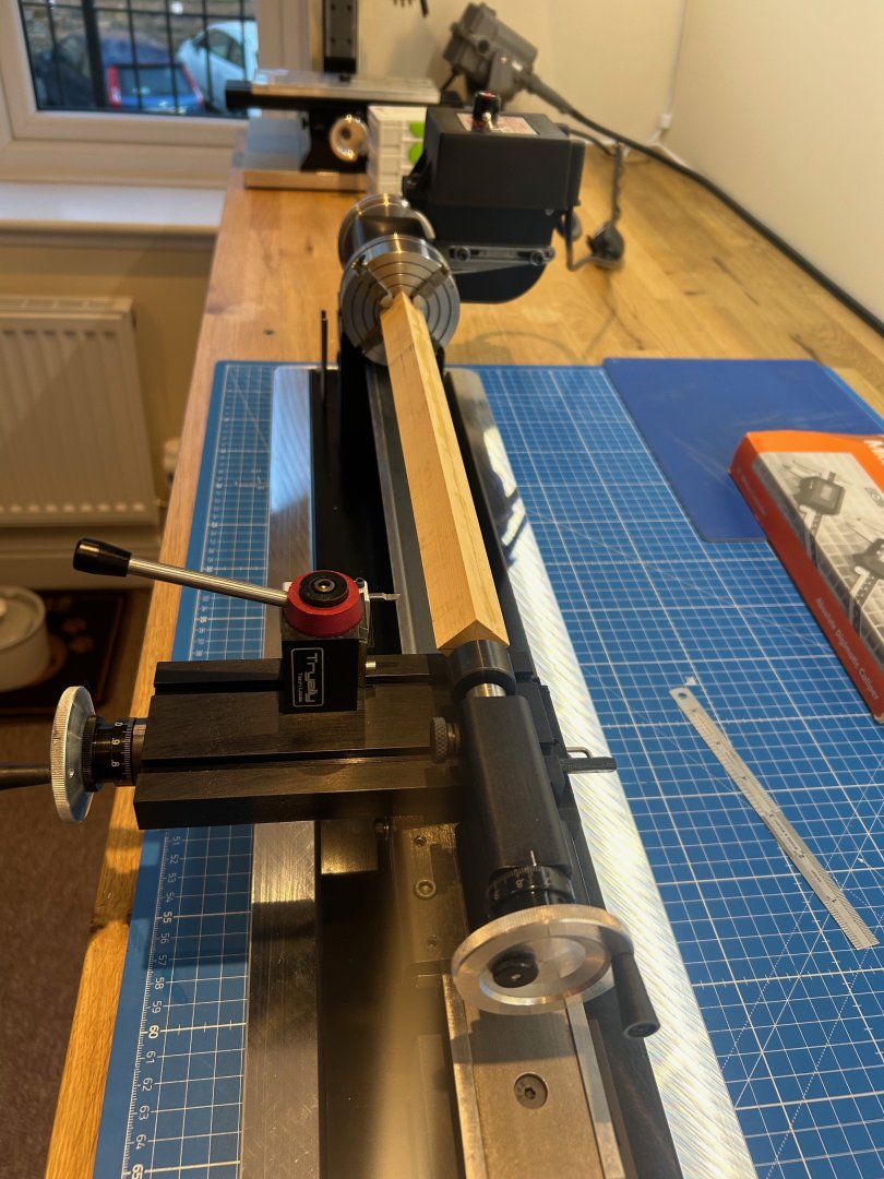
Thanks very much Greg - I did consider reducing the square down to an octagon with a plane you mention but it just gives off different chips. I used a carbide cutter and just went straight for a clean cut rather than taking on the edges. This is pretty much how we did in the tool room when I was an apprentice but it's just such a nice thing to do with hard wood. Mind you the mess pretty much filled the rest of the bag in my extraction vacuum and the chatter is something to behold! The quick change tool post is made by Tryally tools based in Brazil and is made for the Sherline lathe. I cannot recommend this tool post enough as you can adjust the cutter height whist the machine is turning. Once set thats it and it comes with 4 holders for 3mm bits - 4 holders for 1/4 shank bits - 1 holder for a 3/8th boring tool and 1 holder for a 1/4 parting tool.
-
Welcome to MSW Giovi 😊
-
Thanks so much Albert
-
Thanks mate much appreciated Thanks Keith and a very happy new year to you Thanks Brad but remember this is my first POF build so I'm a beginner too. I do get lots of help especially here at MSW.
-
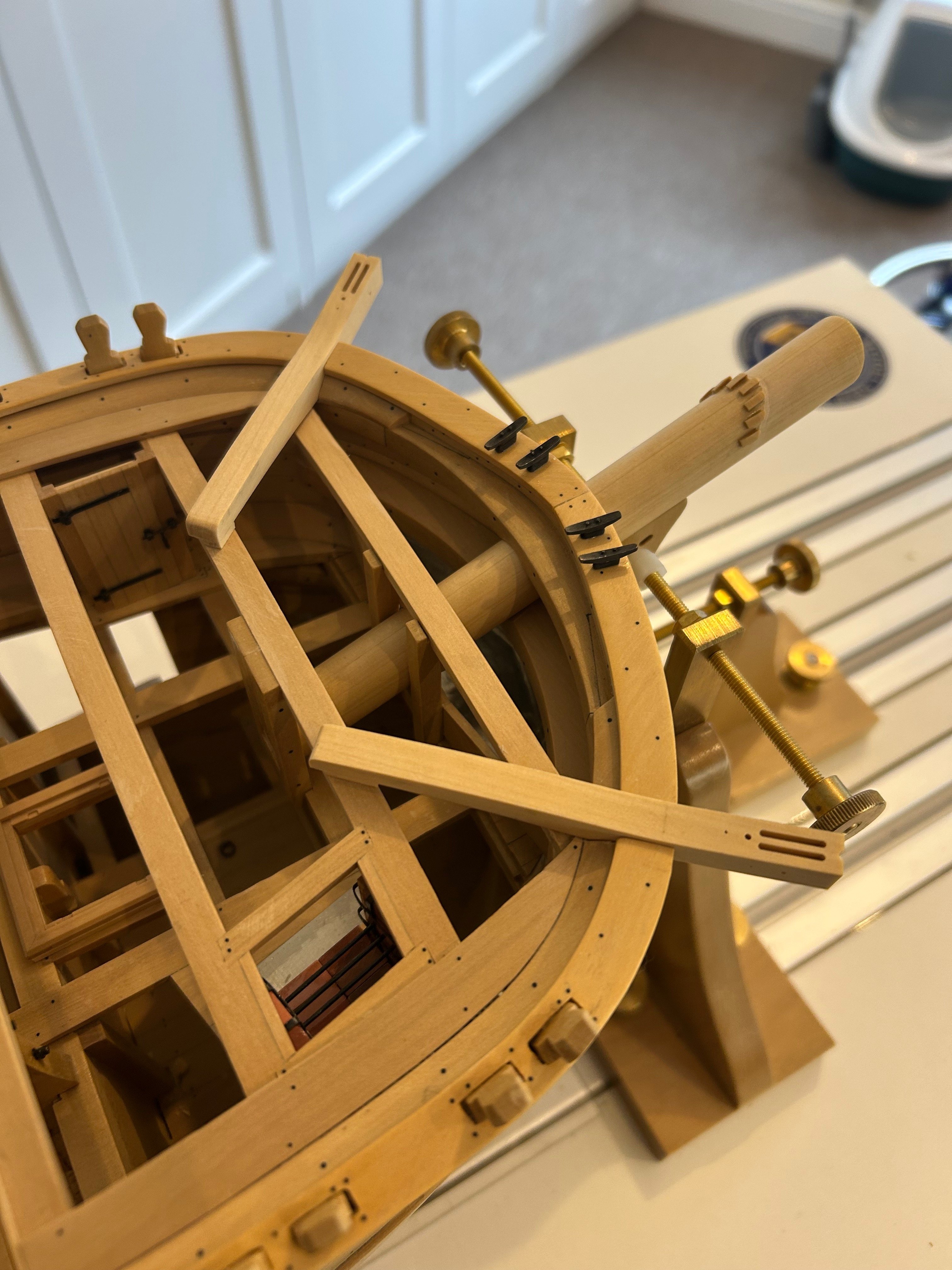
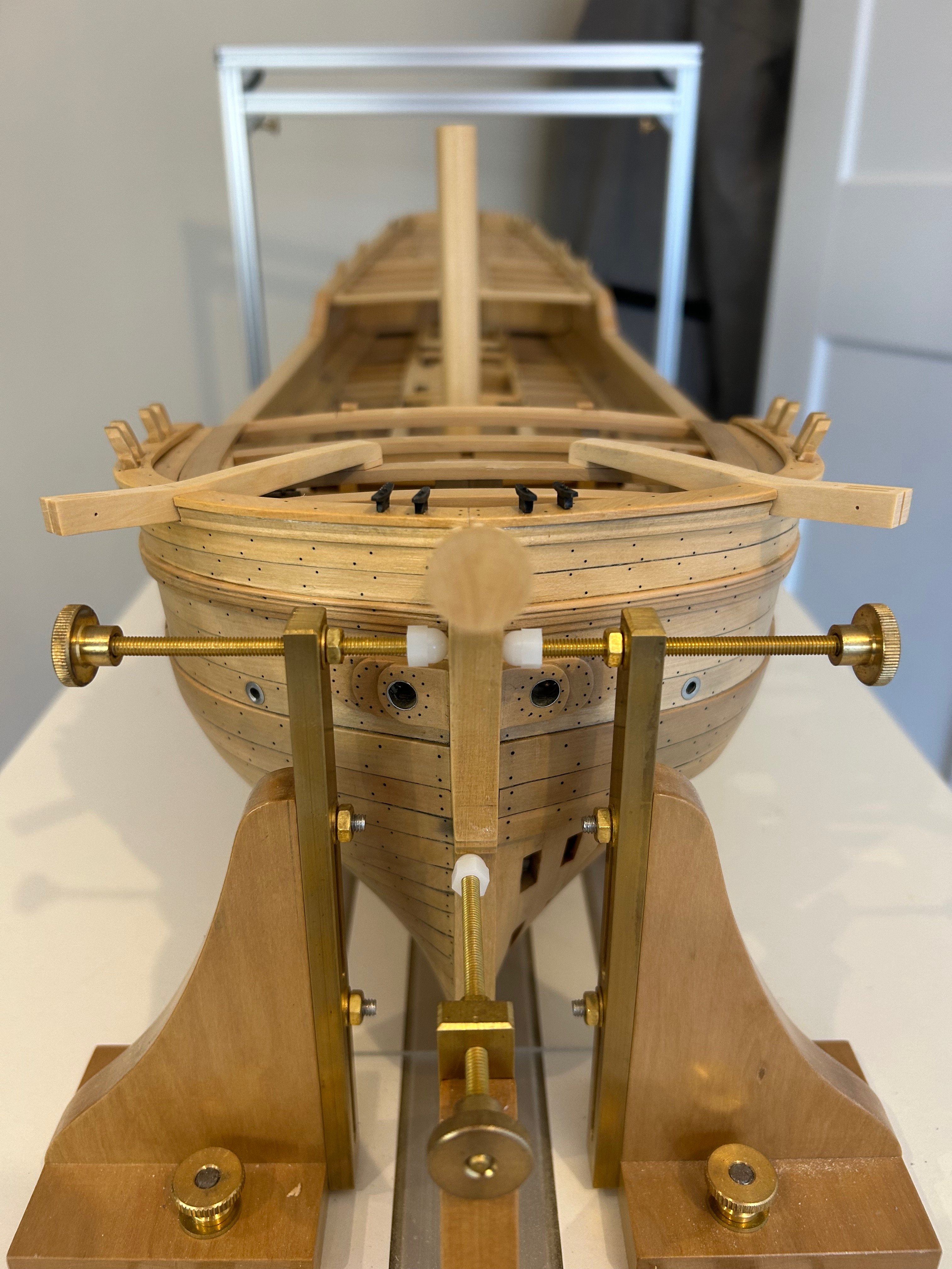
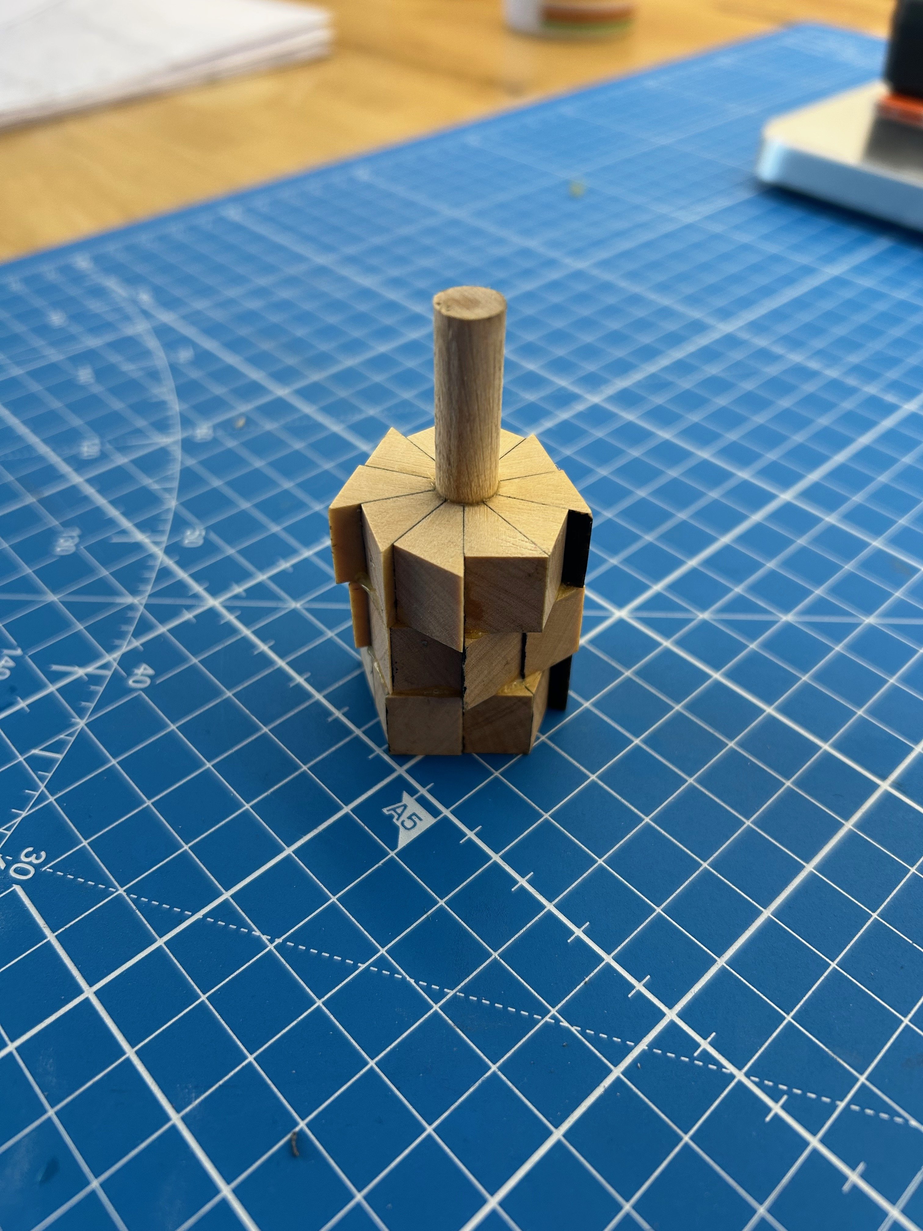
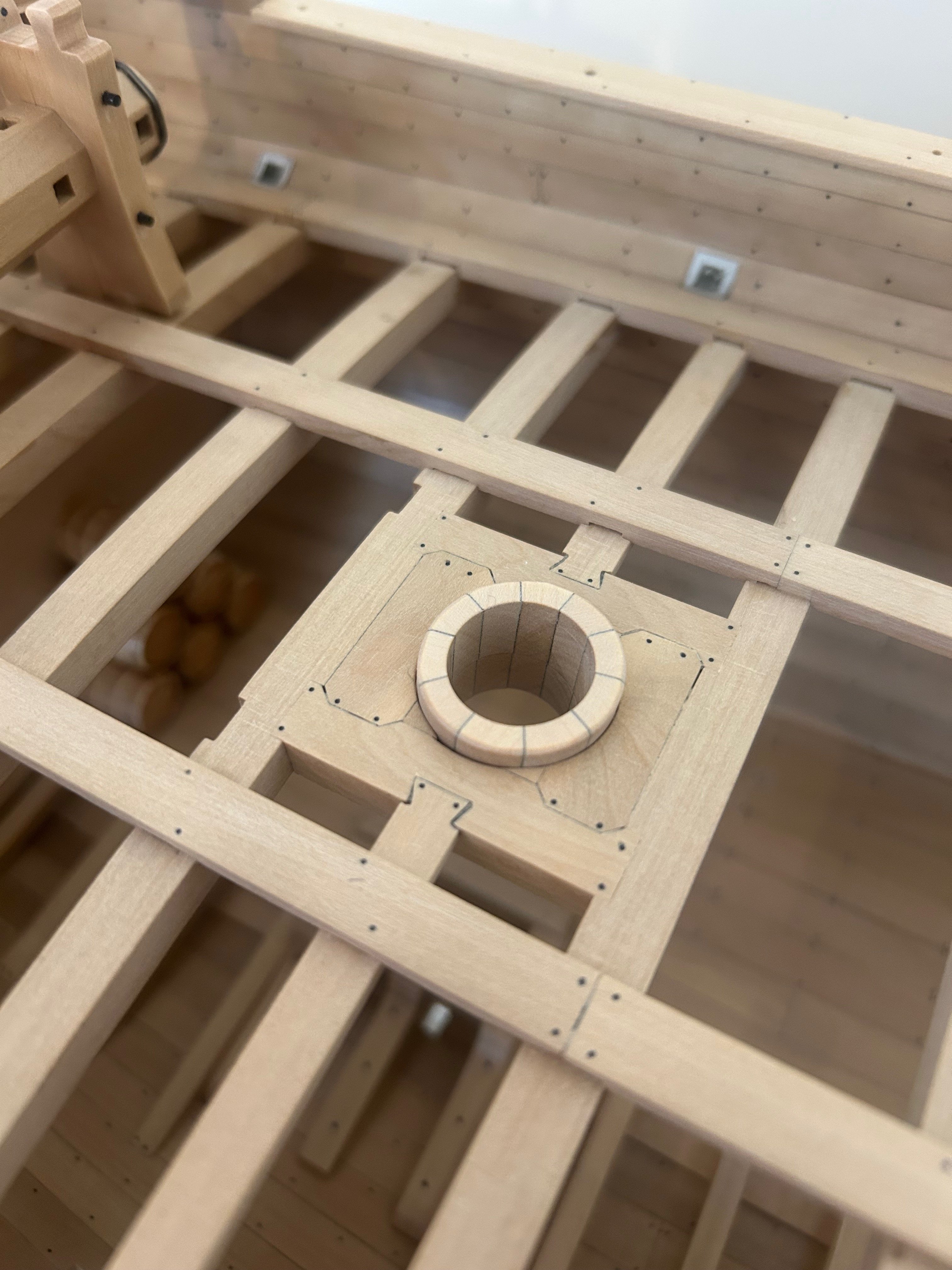
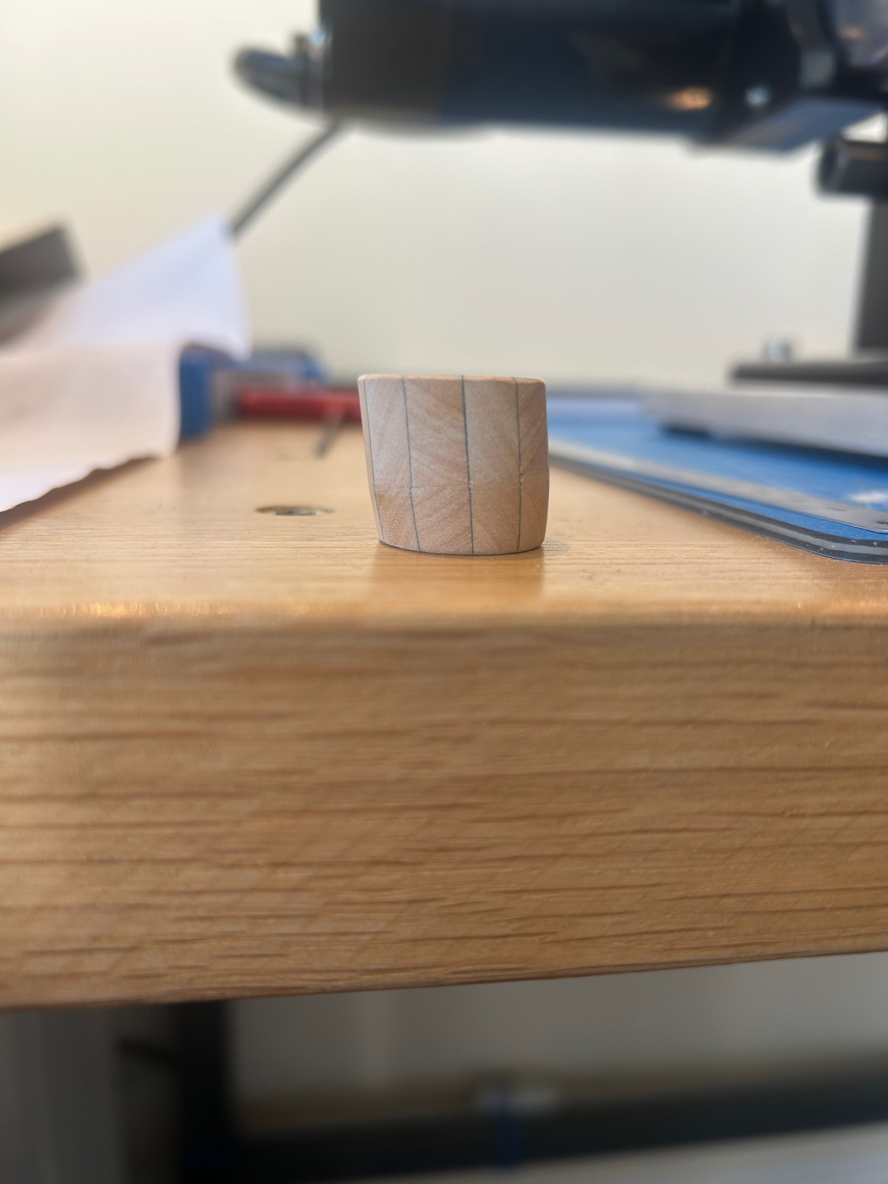
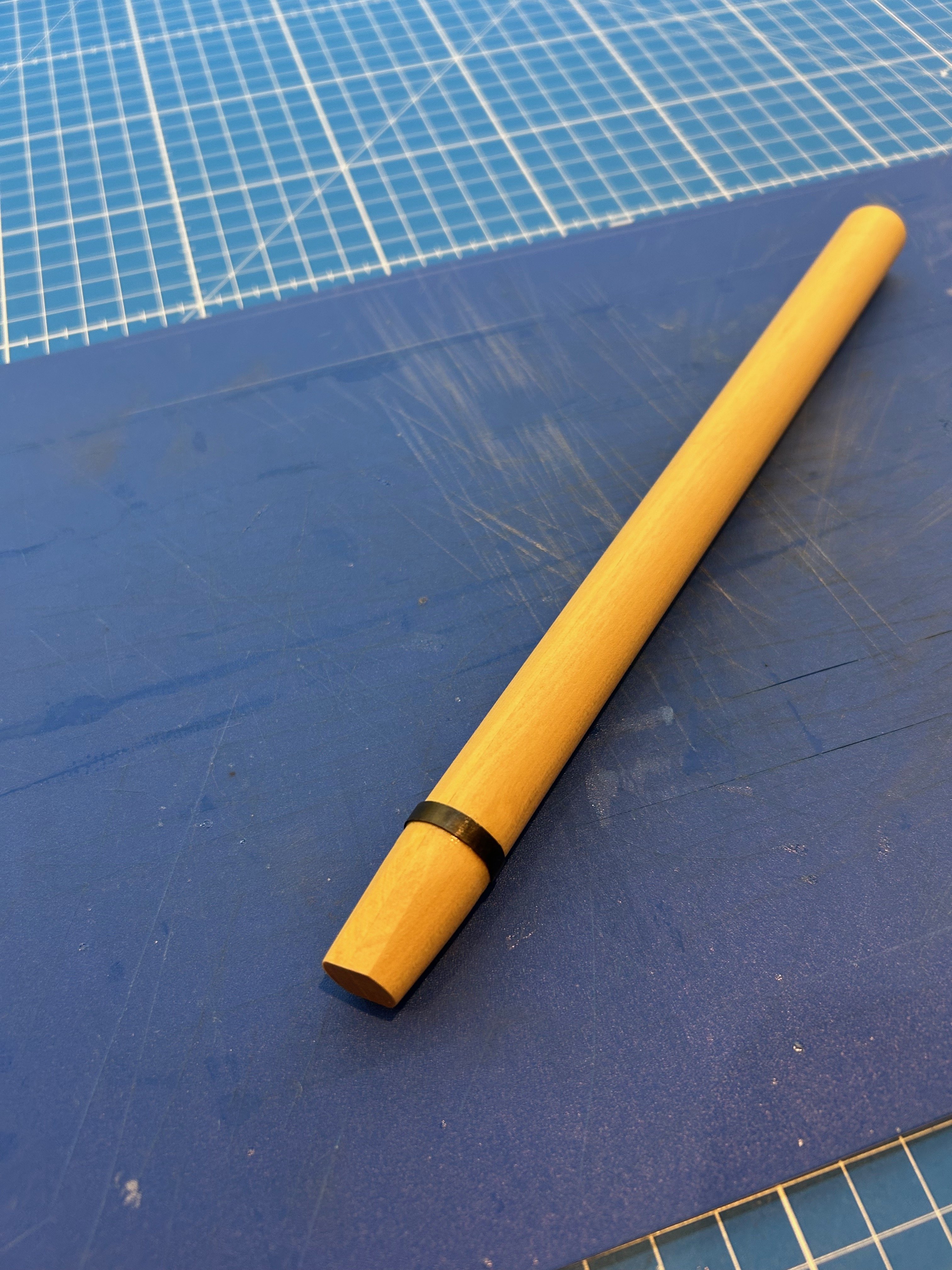
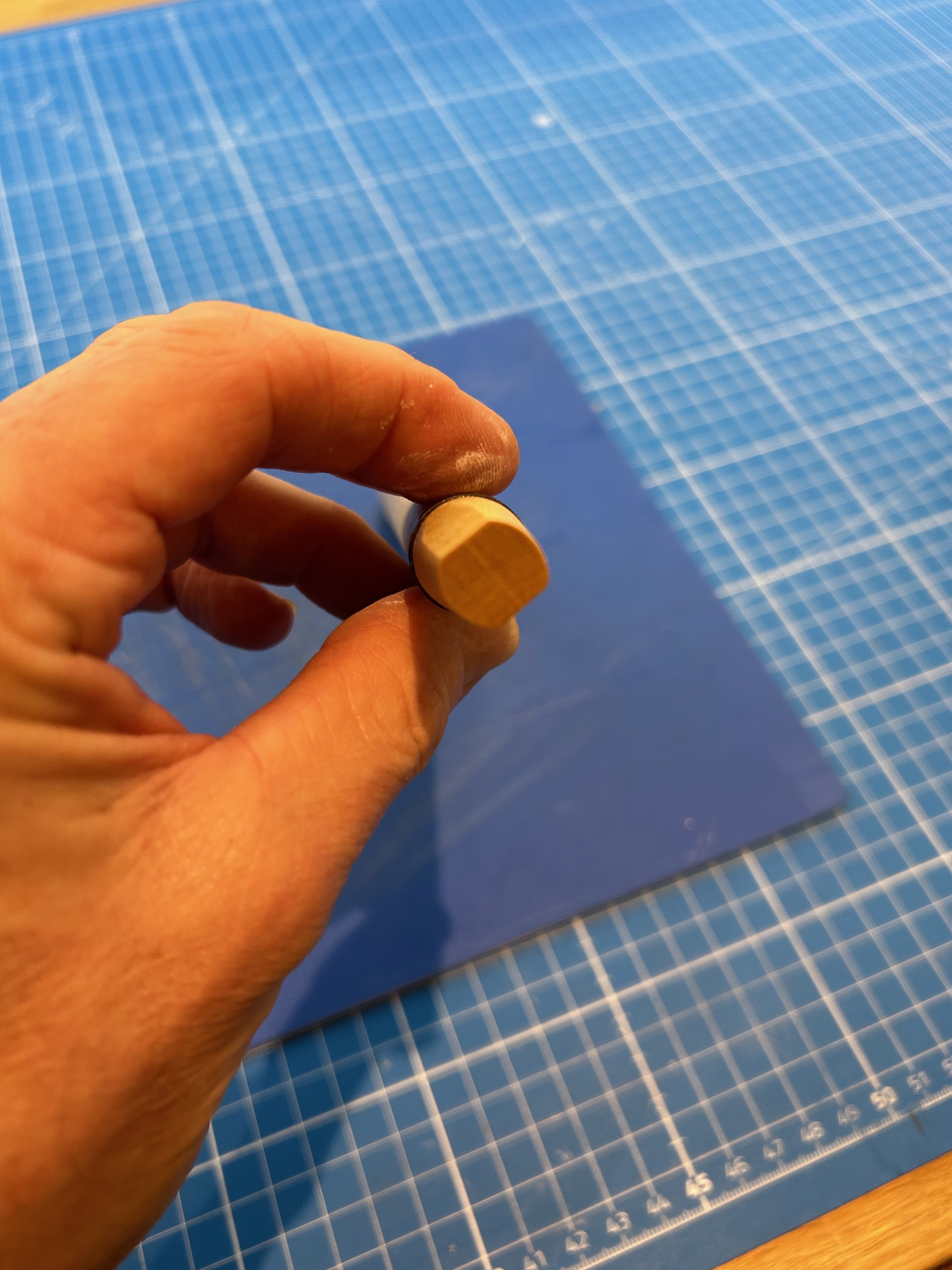
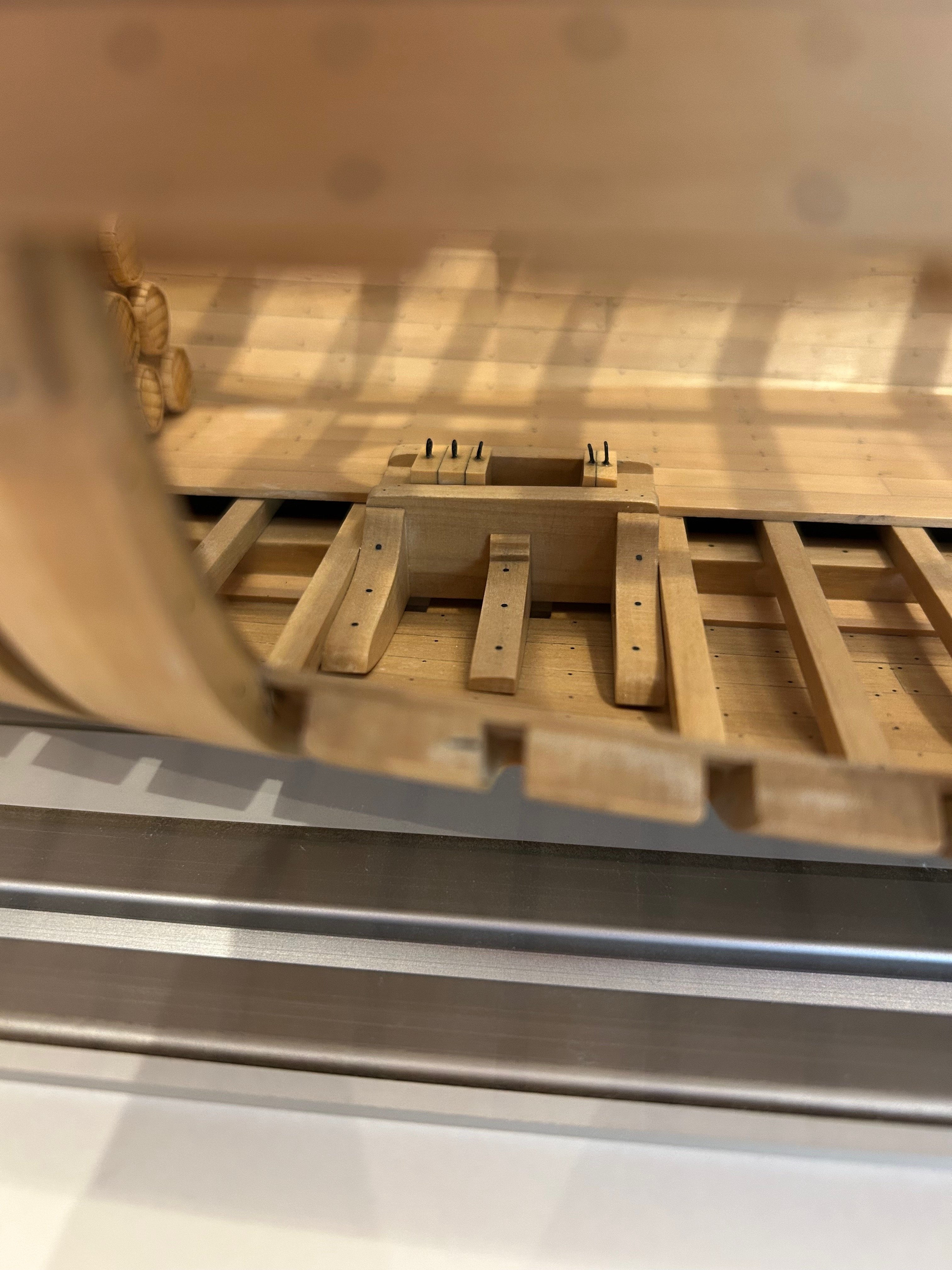
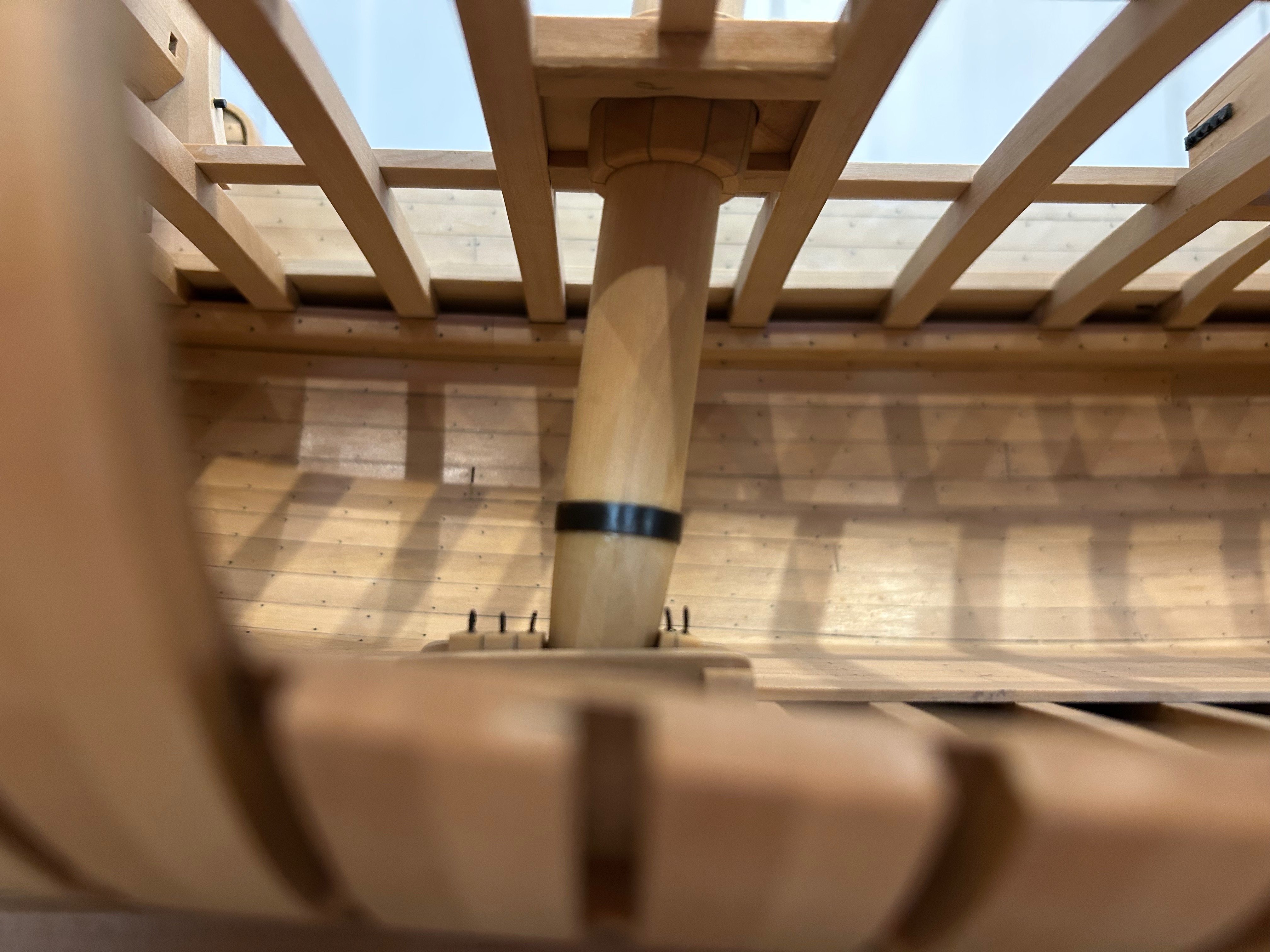
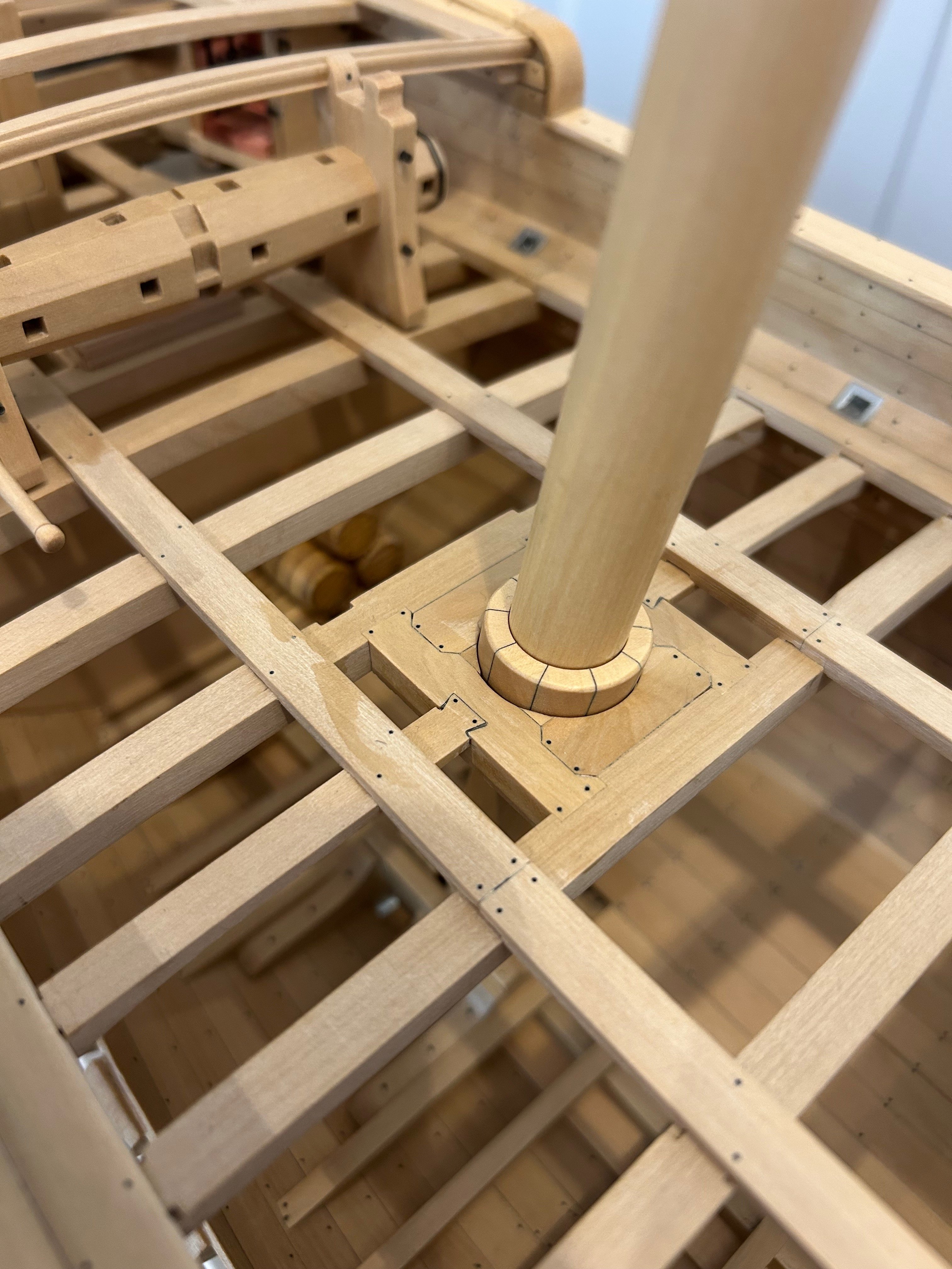
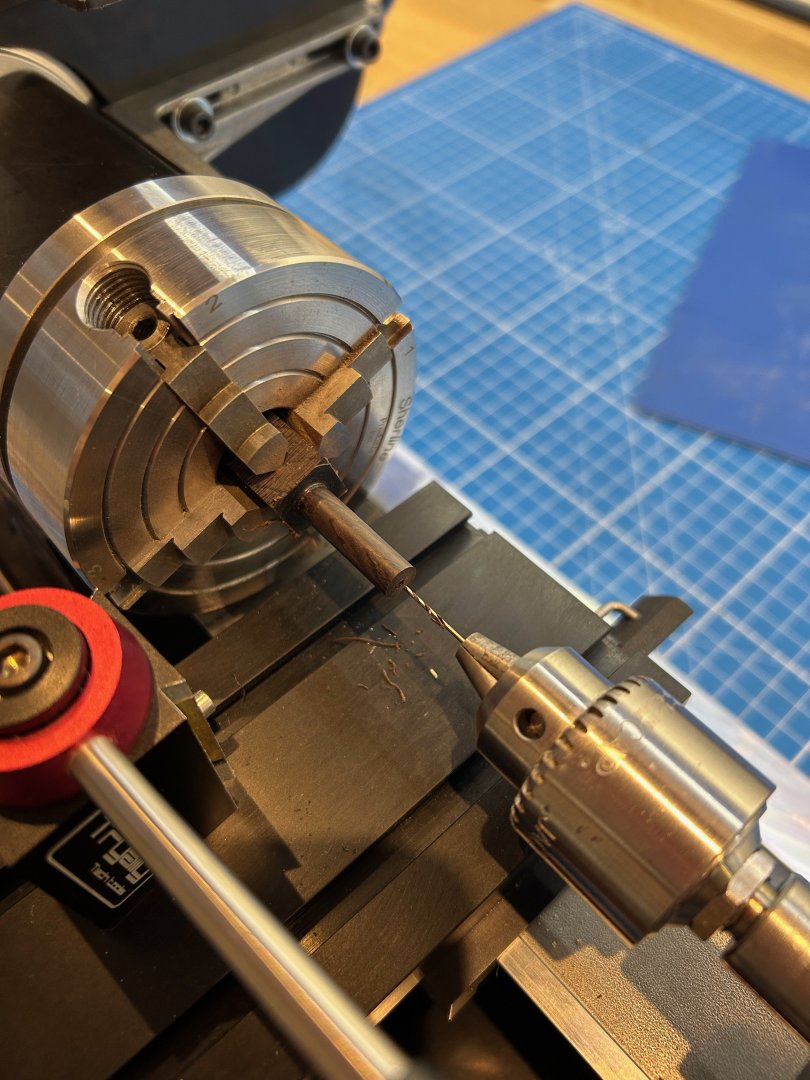
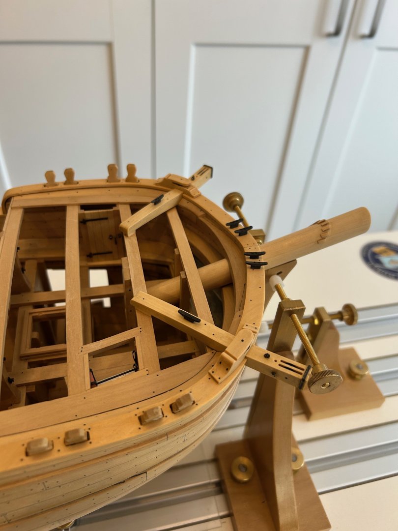
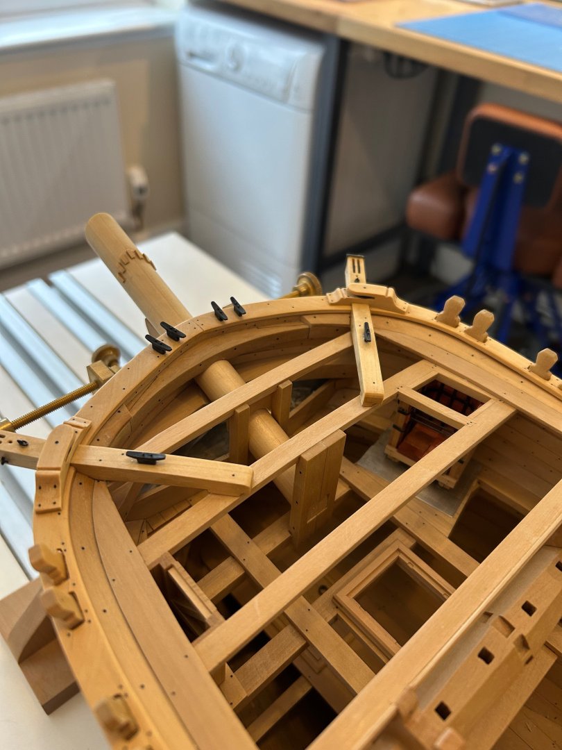
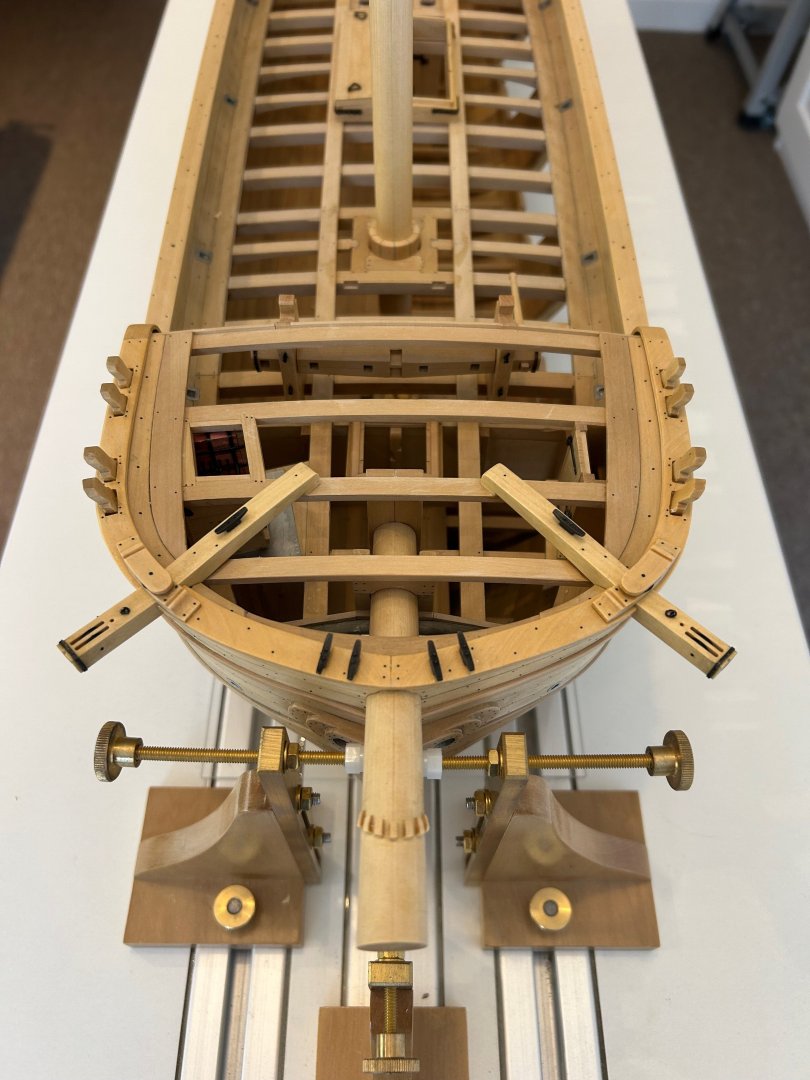
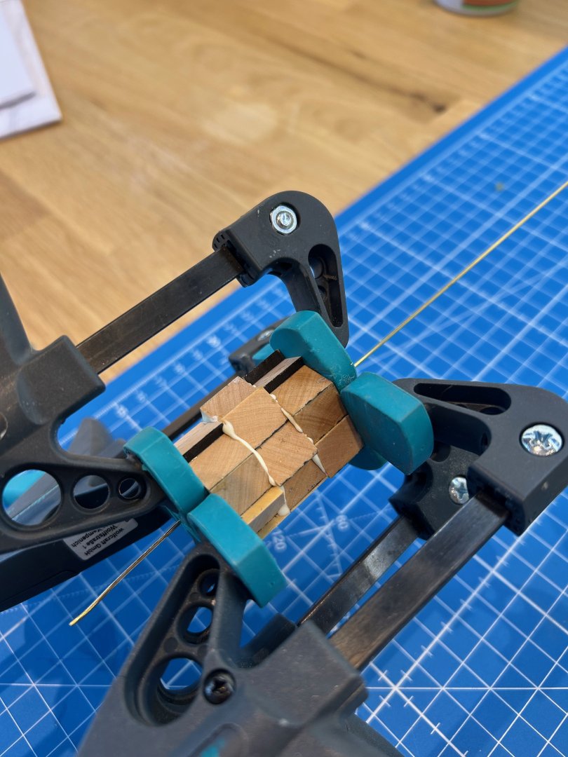
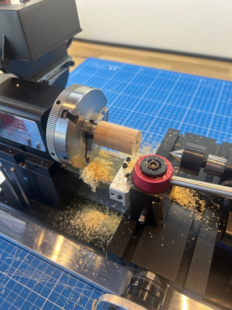
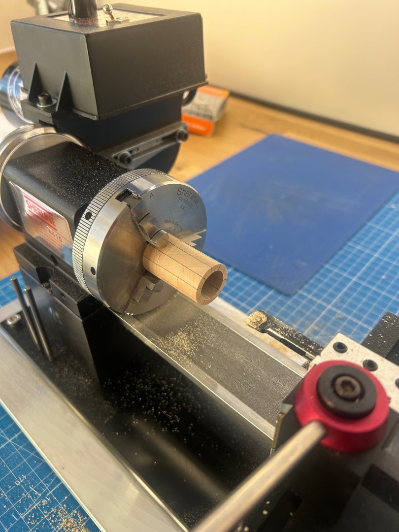
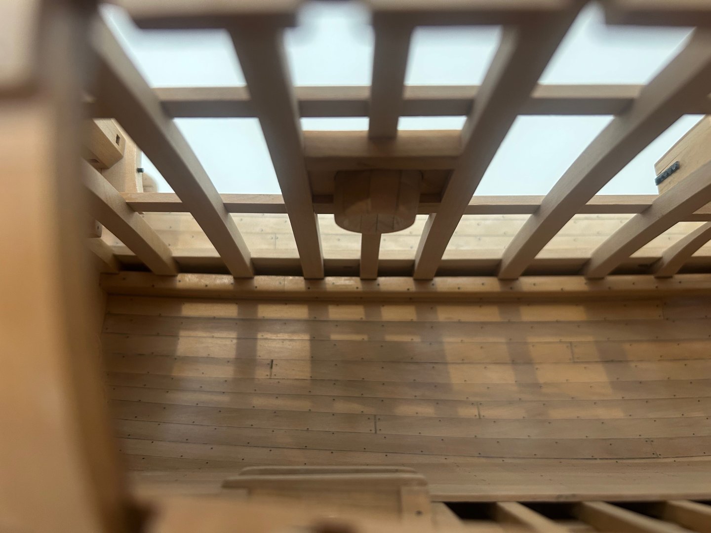
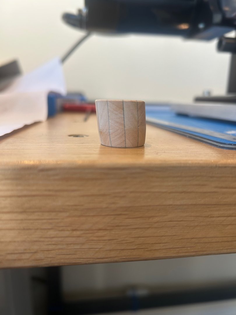
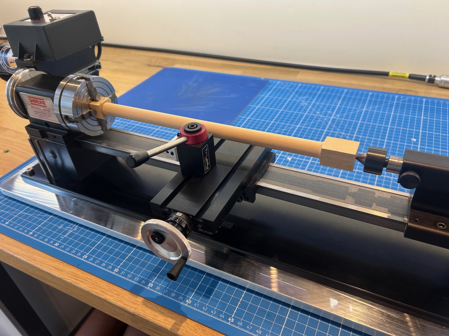
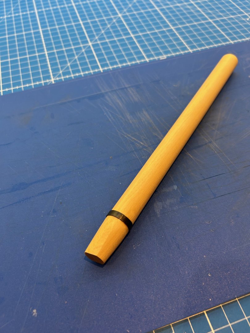
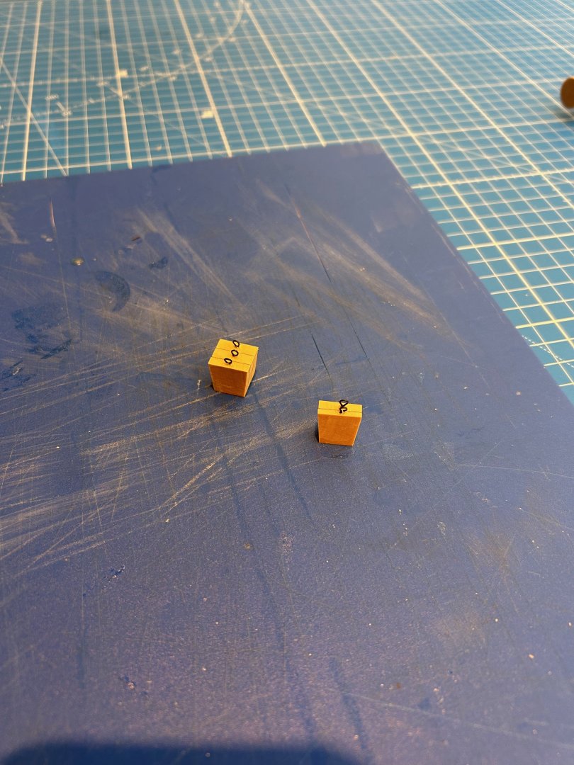
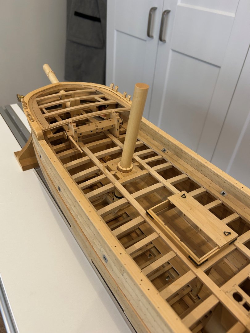
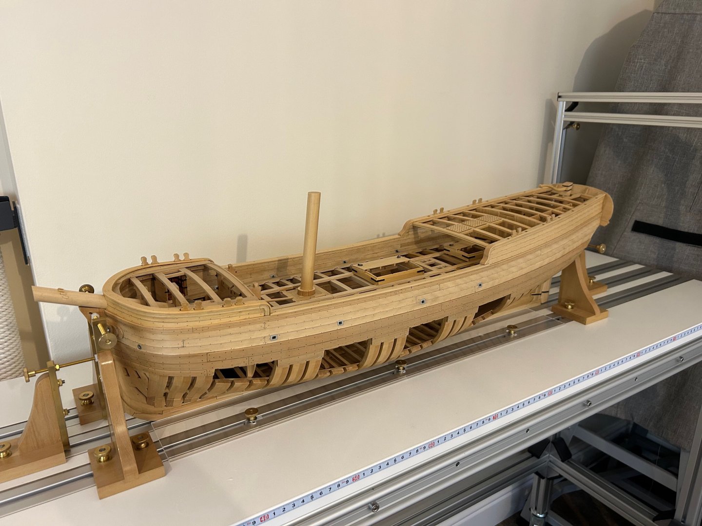
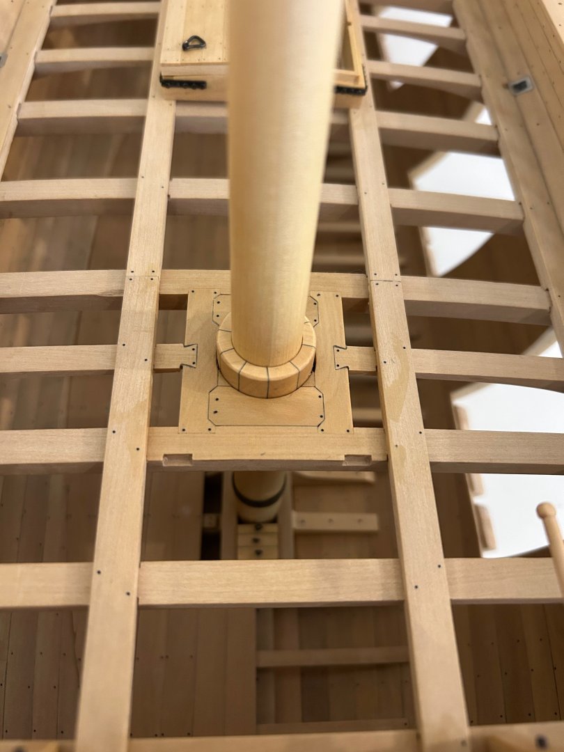
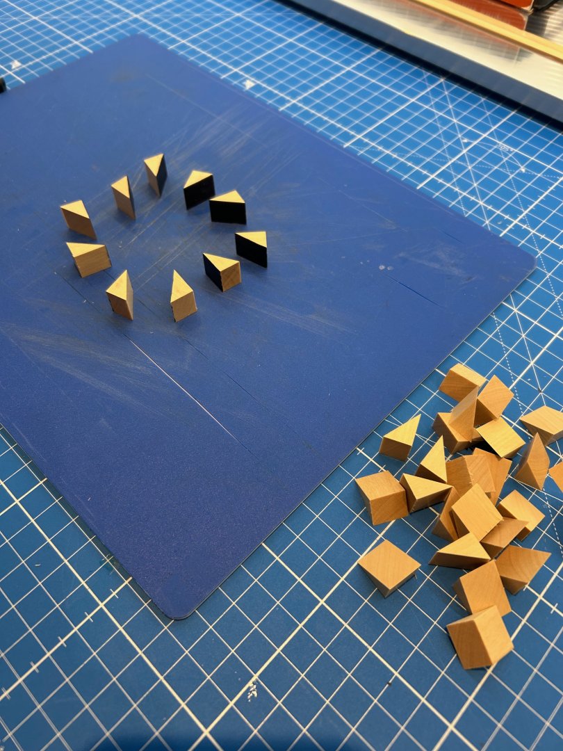
Some more work done and this time it's the main mast and chocks. I'm not rigging this ship so the mast is just going to be a stubby. Sorry this post is going to be a bit picture heavy so firstly the main mast. I didn't have timber with a big enough dimension to make the 16mm diameter mast. So I glued 4 equal pieces together which I ran through a thickness sander to get a good flat gluing surface. This piece was then placed in an independent 4 jaw chuck and supported by a live centre. This was then turned to the required diameter - this was easy with wood but I don't think I'd try a length of metal like this without support. Next was to cut it to length; make the iron band to prevent the base of the mast from splitting and also shape the base to sit in the mast step. The mast partner also required finishing and I wanted to make a nice feature of this. I had the problem of cutting 10 pieces at exactly 36 degrees and I just don't have the equipment to cut such long pieces accurately. So I decided to make it out of 30 individually cut pieces all glued together and then use a glued in dowel to be able to mount it in a chuck. Next I turned the inner and outer dimensions and once this was done sanded the end faces to 7 degrees to match the final angle of the mast. The piece in place on the main deck Then I made the mast step chocks - the one on the left is also cut at an angle to match the mast. Finally all of the pieces are assembled and fixed into the hull. I think my next job is going to be the catheads but I'm not sure yet Cheers Mark


-
Ah ha now I understand 🙂. Thanks druxey I can see exactly what you mean now and why. This is an easy fix too - much appreciated
-
Welcome aboard!
-
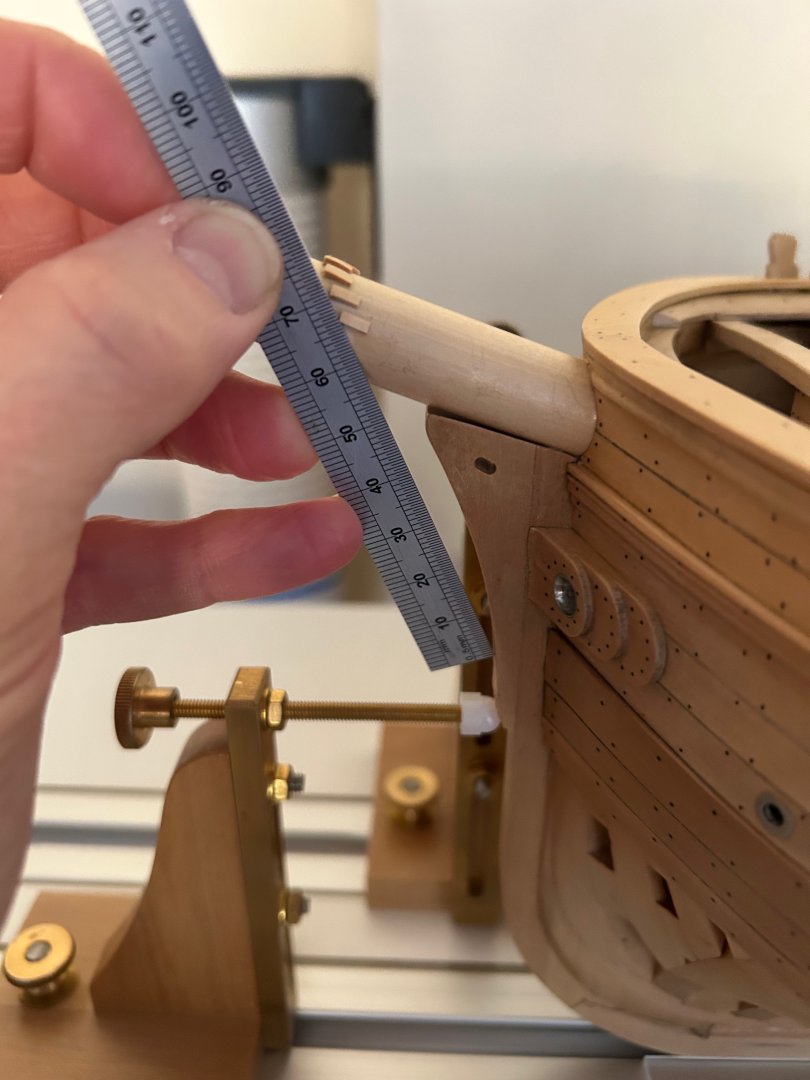
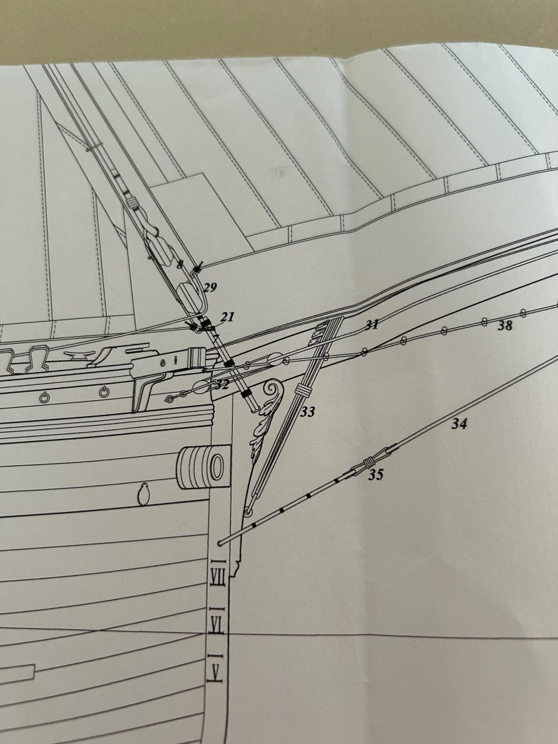
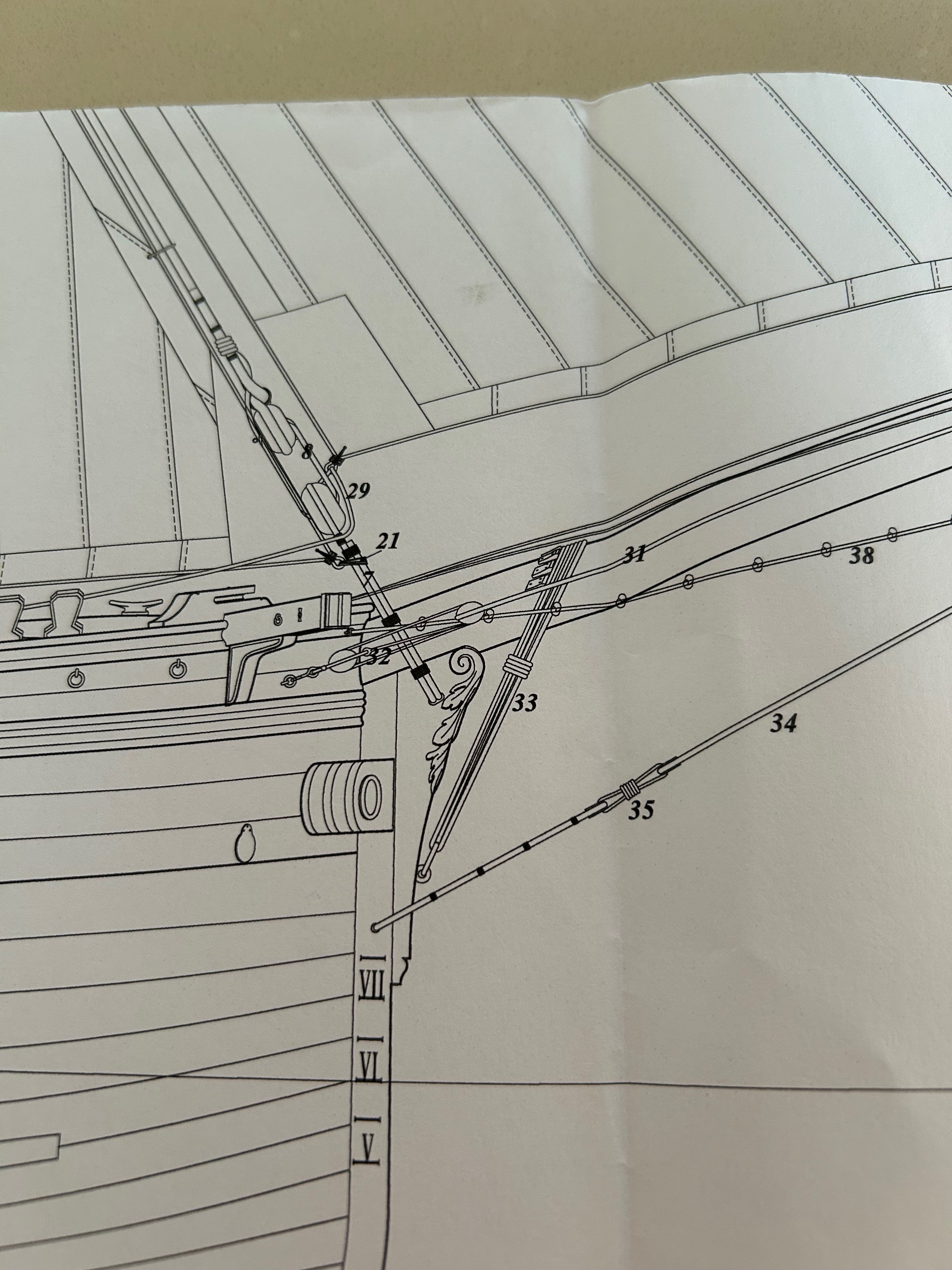
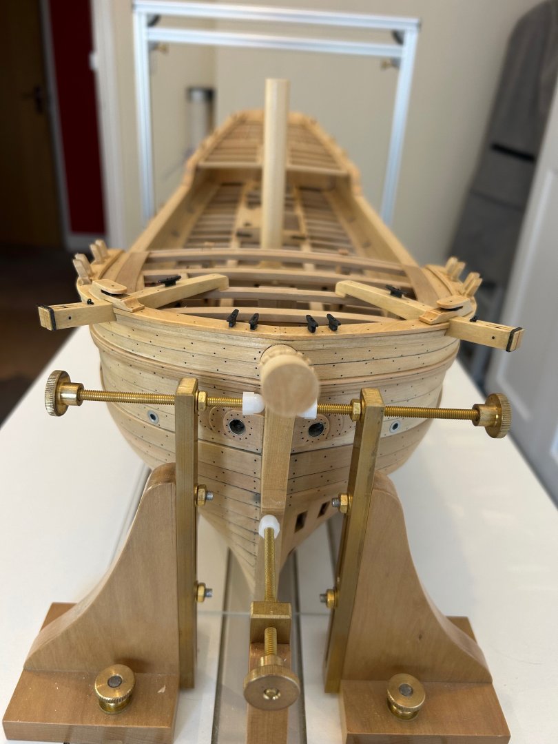
Cheers druxey - I think I know what you mean about the faces of the cleats and I think I have got them just about spot on. The rope is tied to an iron ring further down the stem. Here's a couple of pictures - fortunately I can easily change them if they are in fact not correct. Let me know if you think they need moving.