


druxey
-
Posts
13,086 -
Joined
-
Last visited
Reputation Activity
-

 druxey reacted to ClipperFan in Staghound 1850 by rwiederrich - 1/96 - Extreme Clipper
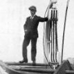
@Snug Harbor Johnny your words and insight are great encouragement. I may be incorrect but it's my estimation that our small group's recent three year reconstruction of Donald McKay's clipper Glory of the Seas involved the most in-depth and exhaustive investigation into a McKay clipper ship in history. I was inspired by Rob's desire to accurately create a model which merged with my wish to finally see McKay's magnificent vessel be given her true appearance. Our efforts eventually drew attention of author Michael Mjelde who's unquestionably the world's foremost authority on McKay's final clipper. It was his knowledge, guidance, and input involving numerous documents and amazingly clear photos which proved invaluable in our efforts. This discipline led me to re-evaluate other McKay related vessel descriptions by McLean with specific focus on construction dimensions. While studying McKay's premier clipper Stag Hound I read that her forecastle had accommodations for her crew, described as being lofty, well lit and ventilated. Yet forecastle deck height was set at the 5' main rail. That doesn't match with a description of lofty. Further to provide crew accommodations the aft section of the forecastle would have to be enclosed. Windows would be necessary to provide light. Later in the description, stern quarters are 3' below. Rob and I concluded a similar arrangement was set up at the forecastle. Now there's sufficient room for crew. The same quarters were also provided for on the Flying Cloud & Flying Fish. Which means the windlass on these vessels would have been mounted below along with water closets. This makes for a much cleaner working space forward. Another misinterpreted aspect is on the rear coach house on clipper Sovereign of the Seas. Models show a small house yet McLean's description says plainly that the coach house was large with working space on both sides and sufficient space at the stern for steering. Meanwhile, here's a picture of the bow of the Great Admiral which shows that she had an impressive cutwater with carved embellishments but no substantive navel hood as seen on McKay clippers. (Arthur D Edwarde's photographic collection in the State Library of South Australia. They have hundreds of historic images of dozens of clipper ships).
-
druxey reacted to Snug Harbor Johnny in Staghound 1850 by rwiederrich - 1/96 - Extreme Clipper
New discoveries are often resisted when presented. Examples: Sea fossil evidence found in the 19th century on mountain tops indicated that the Earth is vastly older than the approximately 4,000 years suggested by the Bible; Darwin & Wallace described Natural Selection as the mechanism of Speciation (still stubbornly rejected by some even today - there is a 'full size' Noah's Ark in Kentucky where humans cohabitate with dinosaurs); Hubble's discovery in the 1920s that there were other distant galaxies - and not 'spiral nebulae' close to us in a 'small' universe; Continental drift due to plate tectonics; that a meteor triggered a mass extinction 60 million years ago that finished-off the dinosaurs ... So it has been throughout history (ever read Carl Sagan's 'The Demon Haunted World'?). Don't be surprised or disheartened, mate - for your research is appreciated by more than a few among us.
-
druxey reacted to rwiederrich in Staghound 1850 by rwiederrich - 1/96 - Extreme Clipper
Personally, I find it quite disheartening to find such opposition to our discovery. Modelers who profess to seek the highest level of accuracy...shy away from clear evidence. I'm amazed, I was expecting more enthusiasm. I've been researching and building scratch clippers for over 50 years and nothing so evident and clear would ever be dismissed because of, *I Just couldn't see it*. If you've studied Mckay's practices and his attentions...it is clear he was onto something, no other builder partook of.
As far as I'm concerned, my Staghound, (as it has been replicated on Glory of the Seas), representation will include this *navel Hood*, as we have discovered. And I will continue to gracefully point out this omission/error misrepresented on, so many models. I'm that passionate about it. Smooth sailing friends.
Rob
-
druxey reacted to ClipperFan in Staghound 1850 by rwiederrich - 1/96 - Extreme Clipper
@Kenchington probably the best evidence we have been able to reliably evaluate is a treasure trove of Glory of the Seas historic images. Author Michael Mjelde quite generously shared many rare and in some cases never seen before images of her. Included were multiple views of her complex bow structure. Elements Rob and I interpret to be navel (not naval) hoods are very tight configured devices which are literally an extension of the upper hull. They gracefully twist from a "V" configuration to gradually arrive at a vertical curving point. Contrary to more decorative moldings on other clipper bowed ships and barques, these are three times as big and offer a substantial perch for the large bowsprit-jibboom spars installed just above. Both @rwiederrich and @Vladimir_Wairoa build logs feature many of these crystal clear images. In fact, true to Duncan McLean's evaluation of the unique toughness of these structures, clipper Glory of the Seas survived a collision when a steam ship accidentally backed into her bow. The only damage she sustained was a cracked upper starboard rail and loss of some cutwater carvings. In his description of the bow construct on Flying Cloud McLean stated that the ship would remain seaworthy even with loss of her cutwater.
-
druxey reacted to Kenchington in Staghound 1850 by rwiederrich - 1/96 - Extreme Clipper
You have studied the primary evidence concerning McKay's ships and, from what I can discern here, you have studied the material closely. I'm interested in the conclusions you have reached but not interested enough to drop other research and delve into the evidence myself. So I can comment (hopefully helpfully!) on what you say but I'm limited and, in the end, can only defer to your judgement.
As to why a draughtsman leaves something blank: There are probably too reasons. Either he thinks it very important and does not what to reveal his secrets (and I could point to examples of that) or else the thing left out had no interest for him, at least in the particular drawing (and lots of examples of that too!). The image you posted last evening, labelled "original plans", shows the lines plans. Maybe McKay simply didn't want to engage with purely decorative detail when drawing the lines of his creation.
I do agree that any figurehead must be firmly fastened to the hull, or it would swiftly be lost. (Attached to the hull and not, I strongly suspect, to the bowsprit -- though if someone produces evidence to the contrary, I would not be shocked.) 2D imagery can fudge the details of the connection but 3D models should have some realistic structural link. If you find that past models lack that (maybe have only an angel's feet resting on solid timber), then they are clearly deficient. I applaud your efforts to do better!
A thought: Some figures, once moved to museums and examined off their ships, prove to be sort of 3-sided, with a deep slot running where a human spine should be. If one of the various pieces that make up the upper stem (the stem itself, gammon knee, cutwater etc.) was extended forwards, it would be possible to insert that piece into the slot in the figure, bolt all together and have the figure well attached without a casual viewer noticing how the attachment was achieved.
-
 druxey got a reaction from BANYAN in Syren Ship Model Company News, Updates and Info.....(part 2)
You absolutely should keep your process proprietary, Chuck. The time as well as cost you've invested should produce a return for you. You didn't invest in all that to produce a dozen 'me too' knock-off merchants.
-
 druxey got a reaction from uscharin in Norwegian sailing pram by Kenchington – Model Shipways – 1:12
But we do! See SeaWatchBooks:
https://seawatchbooks.com/products/swan-iv-sail-making-supplement-from-the-revised-and-expanded-edition-by-david-antscherl
-
druxey reacted to catopower in HMS Wolf 1754 by catopower - FINISHED - Shipyard - 1/72 Admiralty Style - CARD
Still working on finishing up my "inherited" Yacht Mary build. It's actually been nice working on wooden ship models for a bit. I'm now waiting for an order I place with Syren Ship Model Company, so I thought I'd pick up a little side task that's related to this HMS Wolf build.
Specifically, I've been playing around with my AnyCubic Photon Ultra. This is a dip resin printer, for those that know about these things. I got mine a couple years ago. I don't use it a lot, particularly since I don't really know much in the way of 3D CAD work, but I've acquired some 3D print files for some figures that should go well with HMS Wolf.
I printed them out prior to the weekend, and I've been trying to modify them a little and paint some of them. HMS Wolf, being a brig should be commanded by a Lieutenant with a midshipman as an assistant. So, below, I painted what I believe is the correct uniform for a lieutenant, shown on the right side of the photo below. To his left is his midshipman, then petty officer and sailor.
Not too happy showing photos of the figures, as they look much better to me by my unaided eyes. It's been a long time since I've done much miniature figure painting, and I did a LOT back in the 80's. So, these are 1/72 scale. Hopefully, these uniforms are right. I'll be painting a handful of sailors as well. Haven't decided how many figures I would put on the model, but I think it will be nice to have a few for scale reference.
-
druxey reacted to Oliver1973 in La Belle 1684 by Oliver1973 - 1/36
The cleats correspond geometrically to the small cleats on the wreck. As I don't trust glued cleats, I will also secure them with a bolt.
The 3mm rollers will be installed in the crane beams, mast cradles and the fixed snatch blocks on the railing. According to the wreck, La Belle only had wooden sheaves and axles. Before installation, the parts are cleaned again, the cleats rounded, etc.
-
 druxey got a reaction from SeaWatch Books in Ships in Scale Magazine Sails Again!
Best wishes as you plan the relaunch of a valuable resource in contemporary form.
-
druxey reacted to Chuck in Syren Ship Model Company News, Updates and Info.....(part 2)
Placeholder for the kit instructions of the Speedwell Battle station. The kit will be given away at the Joint Clubs show this Saturday. But I will be heading up a group build at out local club in New Jersey. The goal for our small club was to create a teaching mini kit to help describe one method for doing three things. I will also be distributing a bunch of these small kits here on MSW.
-Building a cannon carriage with a jig
-Rigging a cannon with a simplified approach
-Painting small figures for your ship models.
The last tech group tech session will require a separate set of instructions for the group to be made later.
Mono
SpeedBattleStationInstructions.pdf
Plan sheet
joint clubs.pdf
Material list
list materials.pdf
I have been asked by so many people to NOT make this a limited edition kit at all.... and because it would be a great opportunity for other local clubs to also use it as a group build. I havent decided yet. Same is true with doing a group project here at MSW because this is something that wont take several years to finish and it is a very quick project. Plus it has three main points of teaching that is commonly asked about by new and intermediate builders. Granted this is just one approach to doing them all. But it would be interesting to see some of the other approaches. The instructions attached contain a very detailed step by step for rigging the cannon because that was one of the main focuses for my club group build. The kit also contains a jig for making the gun carriage.
-
druxey reacted to Chuck in Syren Ship Model Company News, Updates and Info.....(part 2)
I opened the online store yesterday and at the time was nearly fully stocked. But in two days I have seen a huge upswing in sales....huge. I am not sure why. Maybe the tariff situation but I really dont know. Maybe from folks seeing the rope and blocks at the show?
Anyway, I just want to let folks know I am diligently making more blocks and rope...but its going to be a slog. I am down to nearly nothing left in stock right now. I will be working as fast as I can so thank you for your patience.
The "swiss pear" colored 3d printed blocks in particular are literally flying off the shelf. The more folks see and use them, the more I sell. I have all my 3d printers working full tilt. Again thank you for your patience.
-
druxey reacted to Venti in Norwegian Sailing Pram by Venti - FINISHED - Model Shipways - 1:12
Got a little done on the sail. Got the gaff and boom connected. Got some of the thread wrapped around stuff. Is this all called rigging? The step says lashing but maybe that's just rigging the top of the sail to the gaff? Idk. I used entirely too much CA to hold the knots where I wanted them. I think I have the boom too far out (? Away from the mast) so the sail won't be parallel to the mast.
A little more to go and she'll be done.
-
 druxey got a reaction from Tony Hunt in Staghound 1850 by rwiederrich - 1/96 - Extreme Clipper
Just catching up; a fascinating discussion, gentlemen!
-
druxey reacted to SeaWatch Books in Ships in Scale Magazine Sails Again!
I'm excited to share some news that I think many in the ship modeling community will appreciate—Ships in Scale magazine is coming back!
SeaWatch Books has worked out an agreement with the Nautical Research Guild (NRG), who owned the Ships in Scale brand after the magazine’s original run. We're now relaunching Ships in Scale with the goal of honoring its rich tradition while expanding its reach for today's modelers. We'll be featuring a wide range of articles for all skill levels, detailed build logs, kit reviews, and broader maritime topics, supported by a new digital platform as well.
If you'd like to learn more about the plans for the relaunch, I’ve written a short article that you can read here:
Read More →
We’re looking forward to building something that supports and celebrates the incredible craftsmanship, creativity, and passion in the ship modeling hobby. Thanks for taking a look!
— Mike Ellison
Publisher, Ships in Scale
SeaWatch Books
-
druxey reacted to ClipperFan in Staghound 1850 by rwiederrich - 1/96 - Extreme Clipper
@sob @rwiederrich and I have both been doing a very deep dive into Donald McKay's remarkable California clippers for 16 years now. While the vast majority of that time has been concentrating on his last magnificent medium clipper Glory of the Seas, it naturally led to examination of his other earlier clippers as well. Our research has led us to some startling conclusions. I personally have been astounded to discover how effectively Donald McKay disguised his nautical bow construction which Rob and I now refer to as the unique McKay bow. Beginning with Stag Hound his inaugural clipper, Duncan McLean a sailor himself and apparently good friend of McKay's describes this vessel as: "Not only is she the largest of her class afloat, but her model may be said to be the original of a new idea in naval architecture." There are 3 components described in the Stag Hound bow: (1) stem, (2) cutwater and (3) hood ends. " The whole rake of her stem on deck is 6 feet, and of her sternpost 2 feet." "An idea of its sharpness may be formed from the fact that, at the load displacement line (as the cutwater is tapered to an angle), a flat surface applied to the bow from its extreme, would show no angle at the hood ends. "A carved and gilded stag hound, represented panting in the chase, and carved work around the hawse-holes and on the ends of her cat-heads, comprise her ornamental work about the bow." Using published Stag Hound lines, I overlaid (2) cutwater and (3) navel hood over the (1) stem adding the stag hound panting in the chase as described. Carved work, just as on Glory of the Seas would embellish both cutwater and navel hoods identically. There's a precise scale included off the port bow of the sketch. One observation I've made is that Duncan McLean is long on construction details and short on describing ornamental work. When he describes Flying Cloud for the first time, McLean actually uses the nautical term "navel hoods." In fact, he makes his most in-depth observations of any McKay bow in his evaluation of the strength and ruggedness of this California clipper fleet bow. "She has neither head nor trail boards, but forming the extreme, where the line of the planksheer and the carved work on the navel hoods terminate, she has the full figure of an angel on the wing, with a trumpet raised to her mouth. The figure is finely designed and exceedingly well executed, and is a beautiful finish to the bow. It is the work of Mr. Gleason, who made the figure-head of the Shooting Star." "Her hood ends are bolted alternately from either side, through each other and the stem, so that the loss of her cutwater would not affect her safety or cause a leak." Utilizing the same published lines for Flying Cloud I reconstructed her complete bow as she's been described ever since the Boston Daily Atlas article was published over a century ago on April 25th, 1851. Admittedly it's tough to see since it's so dark but the very first color woodcut illustration of her being launched includes a wedge-shaped design just above and behind a white winged trumpet bearing angel which the artist used vertical lines to delineate. Just like Glory of the Seas the top line of this shape just happens to align directly with the planksheer molding. A couple years ago I discovered this fascinating oil in an Australian Maritime Museum titled "Flying Cloud off Whitbey, North Yorkshire 1871" by John Scott. Twenty years after her launch, she still has her trumpet bearing winged angel mounted in front of her gilded carved navel hood over a carved cutwater. Typical of older wooden clippers, her once lofty rig has been reduced and her once deep topsails have been replaced with Howe's rig upper and lower topsails on all masts. Another beautiful contemporary piece I found is: "Ship 'Flying Cloud' Alex Wagner, Cmdr, of New York going into Hong Kong." This is an earlier work depicting her when she still had her original taller rig. Detail scene shows a white winged angel bearing a trumpet with painted, carved navel hood and cutwater. Note how in all works, her angel figurehead isn't attached to the bowsprit but mounts below the navel hoods and in front of her cutwater. Artistically portraying these complex shapes is quite a challenge since the prows of these huge clippers were very sharp and their rigs were like skyscrapers. Incidentally, I've personally seen a portion of a substantial iron bar that once mounted the Grecian goddess Athene to her supporting navel hoods on Glory of the Seas when her new Cape Cod owners invited me to see her. I hope this is sufficient evidence to prove conclusively that our understanding of clipper Flying Cloud must be revised to incorporate these unique bow construction components.
-
druxey reacted to ClipperFan in Staghound 1850 by rwiederrich - 1/96 - Extreme Clipper
@sob Scott, since cutwaters and navel hoods were never included by McKay in his lines, his widow would have had nothing to trace. Similarly, no monkey rails, splash rails or figureheads have been found on any clipper ship lines either. Rob, Vladimir, myself and occasionally Druxey have been able to keep our communications civil by agreeing that our mutual goals have been to maintain focus on trying to remain as faithful as possible to Donald McKay's historically accurate vessels. However you envision cutwaters and hood ends (or navel hoods) I strongly believe you must at least concur that as her lines are currently portrayed they only show a bare stem, these other two important elements are currently lacking. Perhaps it's personal artistic bias but the two bow revisions I've illustrated appear to show a more refined impressive and complete clipper prow which gracefully incorporates all elements as described.
-
druxey reacted to ClipperFan in Staghound 1850 by rwiederrich - 1/96 - Extreme Clipper
@Kenchington another contribution which I forgot to mention before is that I sent my second Nautical Research Journal article for review by author Michael Mjelde who's been studying McKay's final clipper Glory of the Seas for 60 years or so. His exhaustive research included actual meetings and multiple conversations with sailors who served on this clipper. He is now author of three fascinating books on this spectacular clipper. The only corrections he recommended to me were minor source quotes. This as of yet unpublished submission includes a detailed evaluation on a number of McKay clippers with quotes from McLean articles, as I've done here. Mr. Mjelde said he enjoyed the article and didn't dispute any conclusions regarding my interpretation or illustrations of the McKay bow structures. If you look very closely at the sets of bow pictures of the only surviving McKay clipper we have, you'll see how tightly the large nautical devices to which the figurehead mounts adhere to the bow. While they have ornate carvings they are far more than extraneous decorations. They were complex structures which actually twist from a "V" curving element to a vertical termination. Such wooden modeling would have required intensive laminations to accomplish. Knowing his California clipper fleet had to be able to smash into some of the toughest, mighty seas on the planet, it's logical to conclude that McKay would devise a more durable prow to endure such conditions. Reinforced bow components, overlaying a sturdy cutwater which in turn attaches and extends the stem provides a far more rugged platform to which a figurehead is protectively attached and the bowsprit is rigged and mounted. It is our contention that this combination of designed components is precisely what Duncan McLean referred to when he said that Stag Hound represented a new form of navel architecture.
-
druxey reacted to Scott Crouse in Muscongus Bay Lobster Smack by Scott Crouse - Model Shipways - 1:24
Time for an update. After messing up the first batch of sails - they shrunk when washed in hot water, I purchases a couple of meters of fabric and started again, this time staining before drawing the lines and cutting.
Although I have access to a sewing machine, I have never used one. So I figured 3 or 4 hours tops to hand sew.... ya no. Took 10 hours to hand sew. In that time I could have taught myself how to use the machine, did 4 practice runs and still make the sails . Now I know!
More of the finishing touches in the cockpit and on the hull. Seats in place and did some metal work and blackened the pieces. Hatch and bow will be next and should get to stepping the mast and adding sails and rigging shortly.
-
druxey reacted to Venti in Norwegian Sailing Pram by Venti - FINISHED - Model Shipways - 1:12
Well the part I was dreading the most is done... I got the mast shaped. I decided to use the dowel and not the square pieces. I'm not sure why they couldn't have given us a smaller dowel sine we had to trim it down so much... I threw it in my drill and started trimming it with some 150 sandpaper. This was so painfully slow... So I got the bright idea to use the Dremel with a drum sander while spinning it in the drill 🤣🤣 I wish I thought of this first because it took off wood soooo fast. I had to be extremely careful though because it was so aggressive. I wish the instructions had more detailed drawings so I could at least have a diameter to aim for.... I keep regretting not spending the $30 for the drawings someone had linked in their log... Won't make that mistake again.
I ended up making my own cleats for the mast because the laser cut ones were so small and looked ridiculous.
I used some of the brass plate I got to make a pad for the boom but I'm not 100% happy with it. It ended up with small dents and scratches 😭 I might still use it though.
-
druxey reacted to Venti in Norwegian Sailing Pram by Venti - FINISHED - Model Shipways - 1:12
Got the boom, gaff and mast done today! Boom and gaff went well, I think I beveled the ends too much so they're pretty small but should be fine. I also sanded the pad on the mast for the boom so it looks significantly better. I haven't glued it on yet because I'm not sure where it needs to be exactly.
I got the mast 99% done. All that's left is to drill some holes and then I can start putting it all together... Easier said than done I think... I got too excited and didn't quite follow the instructions for the mast. Once the 8" x 12" and 3" x 12" sheets were dry I traced the parts needed to be cut and cut them all out. I then just glued them on one at a time until finished. I think the instructions way is harder to make mistakes but thankfully I had no issues.
-
druxey reacted to Paul Le Wol in Pelican 1943 by FriedClams - 1:48 - Eastern-Rig Dragger
Beautifully executed work Gary!. The photo etch bender looks like a nice device to have in the tool box.
-
druxey reacted to Keith Black in Pelican 1943 by FriedClams - 1:48 - Eastern-Rig Dragger
That's neat metal working, Gary. Great construction details and explanation.
-
druxey reacted to Glen McGuire in Pelican 1943 by FriedClams - 1:48 - Eastern-Rig Dragger
Exceptional metal work, Gary.
-
druxey reacted to FriedClams in Pelican 1943 by FriedClams - 1:48 - Eastern-Rig Dragger
Thank you, Keith A, Paul, Jacques, and Keith B, for your comments and support! And thanks to all for the "thumbs up".
I’ve begun work on the Pelicans’ four gallows frames and this post describes some of the preliminary work.
The purpose of these frames is to hang the heavy tow blocks slightly over the side of the boat at about 4 to 5 feet above the main rail. The blocks function as tow points for the trawl and are also used to deploy and retrieve the gear with the main winch.
The screenshot below shows one of the frames outlined in blue. The green lines point out three braces that structurally secures the frame to the boat.
There are no details of these frames provided on the plans, so I drew up my own from a few basic dimensions I pulled from the plans and from photos of period boats.
I took the drawing apart to provide cutting templates for the individual components. The main legs are Evergreen styrene “H” columns, and the top plates were cut from .010”(.25mm) styrene sheet.
The pieces were arranged on the assembly templates and solvent cemented together.
There are several different types of brackets required for each frame and I made them all from brass. After drawing them in CAD, I began by slicing brass sheet into strips of the required widths. In the past I’ve made strips using shears (which curls and deforms them), or by scoring and bending until it fatigue breaks. I’ve even used a guillotine style paper cutter that in certain situations works fairly well. But these methods are not very precise and with some of these strips being quite narrow (.073”(1.8mm)), I wanted to try something a little different.
I used a stainless steel sheet (cutting surface), a carpet knife, a stout straight edge, and 2” wide double sided masking tape (sticky on both sides.)
The secret sauce is the heavy duty masking tape. One piece of tape holds the brass to the stainless and a second piece holds the straight edge to the brass. The tape holds everything very tightly in place to the extent that the straight edge is quite difficult to remove and reposition for the next cut. One could easily bend and ruin a thin metal straight edge doing this.
The setup below is ready for slicing off a quarter inch strip, and as you see from the score marks in the stainless, I’ve already cut several strips of various widths.
The carpet knife is sharp, hard and stands up to abuse like this far better than a hobby knife blade. And due to its geometry, the blade is less likely to chip off, but needless to say I wore proper eye protection. I found repeated light cuts produces a better edge than trying to blast through it with only a few. The brass here is .008” (.2mm) thick, so it only took about seven passes to free the strip from the sheet. The passes feel sticky until the stainless is reached at which time the blade glides easily through. This does leave a bur along the cut edge, but a few swipes with a fine flat diamond file licks them right off.
First to be made are the six bracket pairs (12 total) that secure the gallows frame bracing to the whaleback or pilothouse structures.
The strip is stuck to the template with two-sided cellophane tape and the fold and cut lines are scratched on.
The bracket is clipped from the strip with flush-cut diagonals and the edges are eased with a diamond file.
A bolt hole is drilled through with a pin vise.
The piece is placed into a photo etch bender.
Positioned and squared up.
Then bent.
The gallows have brackets at their feet to allow them to tilt out over the rail.
Eight pairs (16 total) of these will be needed. Holes for the bolt shanks will be drilled later.
A pair of brace brackets on the back side of the frame.
A total of eight brackets are needed.
Each frame gets two chain cleats. Soldered phosphor bronze.
The rod that extends from the center of the cleat will be clipped to length once installed.
And the rod loop which the tow blocks will hang from.
More prep work to be done on these frames, but that's it for now.
Thanks for looking. Stay well.
Gary