


druxey
-
Posts
12,513 -
Joined
-
Last visited
Reputation Activity
-

 druxey reacted to Trussben in HMS Pegasus 1776 by Trussben - 1:48 - Swan-class sloop based on TFFM
Work on the sternpost has begun, complicated lining up with aft deadwood but moving along slowly is fine by me.
Ben
-
 druxey got a reaction from DORIS in ROYAL CAROLINE 1749 by Doris - 1:40 - CARD
Exquisite work on the figures and costumes, Doris!
-
druxey reacted to Rustyj in Bomb Vessel Granado by Rustyj - FINISHED - 1:24 - cross-section
Hi All, It's been a bit since my last post. Life, sub zero temperatures and feet of snow
have all conspired to slow me down. Well the lathe has arrived and the learning curve
is steep but the Sherline is a truly fine lathe. Thanks all for talking me into it.
I tinkered around turning some scraps trying to figure out what I was doing and one
mortar has been made. More coats of paint are needed and then it will be mounted
to the carriage.
The new carriages have also been made. Here is a comparison between the two.
After that the fun continues when I have to try and figure out how to turn two
cannon barrels. Well not only do I have to make two but for some reason they
have to match. Hmmmmm...........
-
druxey reacted to mtaylor in Licorne 1755 by mtaylor - 3/16" scale - French Frigate - from Hahn plans - Version 2.0 - TERMINATED
Update time... Things have not been quiet in the shipyard.
I laminated the plans to some MDF and attached a strip of wood at the reference line. Also attached the stern framing to this so as not to mis-read any critical dimension.
The strip allows me to use the Ed Tool without any induced errors from having it canted slightly.
I've marked all the plans with appropriate reference marks and rescanned them all. Also broke up Version 1.0 in order salvage certain bits.. like everything along the centerline... bitts, grates, pin rails, pumps, capstan, etc., some or all of the deck beams but none of the deck planking. Also salvaged the mast steps and the stern framing. I'll use the stern framing for some references.
I'm currently cutting out with as much precision as I can muster, a new build board. I noted that on the old one, there were some frame notches that we either too deep or not deep enough. Stupidity on my part. I'll be re-using the previous version of the frame squaring jig (on the right in the picture).
Hopefully, in the next week or so, I can start cutting the keel, deadwood, and stem. Since the wood for framing won't be here until early May, I'm planning on building some sub-assemblies such as most of the deck furniture. I've located a local source of good birch plywood, and am considering Woodcraft or the local source for masting materials and some other items.
-
druxey reacted to SJSoane in HMS Bellona 1760 by SJSoane - Scale 1:64 - English 74-gun - as designed
Looking at the images of the Bellona stern again, I see that there is a square transom at the upper deck level, which has to be cut to leave room for the rudder head.
Looking at the images pointed out to me by druxey, there are a number of 74s with curved beams around the rudder head. So here is another interpretation, with a curved joining piece fayed to the fore side of the two halves of the square transom that I see in the Bellona photos.
I am also showing a smaller transom to serve as a landing for the decking just fore of the vertical pieces.
I'll try to build it....
Mark
-
 druxey got a reaction from Trussben in HMS Pegasus 1776 by Trussben - 1:48 - Swan-class sloop based on TFFM
Aft deadwood looks very nice so far! I assume that the 'overhang' at the keel is fullness for insurance at the moment.
-
druxey reacted to EdT in Young America 1853 by EdT - FINISHED - extreme clipper
Young America - extreme clipper 1853
Part 44 –Inboard members continued, Stern fairing and half-frame bolting.
Work continued on the iron strapping with some breaks to work on other things. Other things included installing wood members over the strapped areas. In the first picture a portion of the lower deck clamp is being glued to the frames.
The forward section of the upper deck clamp has been installed at the top of the strapped area. As soon as the clamps are removed when the glue has dried, these members are immediately bolted through the frames with copper wire bolts epoxied all the way through the hole, making an extremely strong connection.
In the next picture a section of bilge ceiling is being installed. These heavy members will fill the area up to the lower deck clamp.
There will also be a few strakes of bilge ceiling below the installed strakes. The iron strapping will also be extended down to the floor heads. The next picture shows one of these extensions. The break in these straps will occur behind frames and will not be visible.
The next picture shows additional deck clamp sections installed, including forward sections of the middle deck clamp.
All these members are epoxy bolted as described above.
Before progressing much further aft with the iron strapping, I wanted to get the aft half-frames bolted securely. They have been held in place since installation only by the end-grain glue joints. I did not want to risk breaking these with the hammering of the strap rivets. Before installing bolts on these frames they needed to be faired. This is easier before the copper bolts are in place.
In the next picture 80-grit sandpaper is being used on the feet of the cant frames to bring them flush with the deadwood.
In the next picture all of the cant and half frames have been faired at their feet. The cant frames, in their scores, end right at the bearding line line. However, the half-frames are not installed in scores but bolted directly to the deadwood. These were not faired to a feather edge at the line but were cut back to about a 3” thickness above the line. The triangular gap was covered with planking. It acted as a limber, or drainage channel, for water that would otherwise accumulate between frames and in the joints between the frames and the deadwood. This feature was evidently not included at the feet of the cant frames.
The next picture shows the feet of the half-frames being squared off above the bearding line.
There will be more to say later about the path of this water to the pumps.
With the model inverted it was a good time to fair the deadwood back to the rabbets in the keel and sternpost. The next picture shows a shallow gouge being used to rough out the shape above the keel rabbet.
This can be risky if not done carefully. In the picture the curl of shaving shows that the gouge is moving parallel to the keel using the pressure of my thumb. I find that cuts go easier at an angle to the edge, slicing the wood - and it is never a good idea to cut toward the rabbet. The gouge is moving in the same direction in the next picture – held as in the last picture with the left hand, in this case pulled gently with the right – always with very light cuts. Do not attempt this with a dull tool.
In the next picture a #0 cut riffler is being used to smooth out the gouge marks. This was followed by 120 then 220-grit paper.
The last picture shows the feet of the half and cant frames after the sanding.
With the final lines of the frame bottoms established the bolt holes were laid out and drilled. These are now ready for the bolts.
There is a lot more sanding to be done on the lower hull, but this much was sufficient to get the bolts in. Now for the other side.
Ed
-
 druxey got a reaction from SJSoane in HMS Bellona 1760 by SJSoane - Scale 1:64 - English 74-gun - as designed
In what you have sketched, it seems likely that the helmport transom tenons into the sides of the stern post. The curve down would be more of a dogs-leg, using naturally crooked timber. The upper deck transom does seem excessively wide. As a result, it might be of two pieces tabled together. Check the NMM 'Collections' site and look at ZAZ1411 for another solution, as well as ZAZ1483, ZAZ1482 and ZAZ2098. This shows the curved beam ahead of the rudder/post and (presumably) a separate transom aft of the rudder head.
-
druxey reacted to DORIS in ROYAL CAROLINE 1749 by Doris - 1:40 - CARD
And today I have finished the chimney above the kitchen - made of card (inside) and clay, so the cook can prepare some delicious meals for us....
Please enjoy the pics and have a great time
Kind regards
Doris
-
 druxey got a reaction from coxswain in HMS Bellerophon 1786 by AON – scale 1:64 – 74-gun 3rd Rate Man of War - Arrogant-Class
Be careful of plan distortion as you go! (This subject has been the topic of many other threads on this site.)
-
druxey reacted to Trussben in HMS Pegasus 1776 by Trussben - 1:48 - Swan-class sloop based on TFFM
Work on the aft deadwood is well underway, also started the sternposts.
Ben
-
druxey reacted to AON in HMS Bellerophon 1786 by AON – scale 1:64 – 74-gun 3rd Rate Man of War - Arrogant-Class
Making some progress.
BODY PLAN LAYOUTS
I needed to delete the reference points in all underlying planes (Station or Buttock Lines) because they showed through to the plane (station) I was working on and it was confusing. I had to go back and clear up “dangling” errors as I had located my water lines to them. Vertical and horizontal dimensions added to the water lines fixed this.
Alan
-
druxey reacted to AON in HMS Bellerophon 1786 by AON – scale 1:64 – 74-gun 3rd Rate Man of War - Arrogant-Class
GOOD CATCH!
Shear vs Sheer ... it was a a typo ... honestly!
I drew the water lines on the sheer (!) plan.
As they are sloping straight lines I needed only the measurement at the stern and bow perpendiculars.
I then open station (or buttock?) line Y (just in from the bow perpendicular), projected the water line locations for "Y" from the sheer plan and inserted and located my points based on the water line height and measurements I had taken off the real plan PDF image.
Then I drew in the shape following the points and then finally mirrored it.
The results are below.
I now only have 30 more to go!
You are right though regarding "proving", and I still have quite a bit to fill in on the sheer plan.
Alan
-
druxey reacted to DORIS in ROYAL CAROLINE 1749 by Doris - 1:40 - CARD
All ropes for Royal Caroline will be handmade on rope-walk machine, some ropes are already prepared and I have decided to remake the anchor rope to achieve more realistic result:
The auxiliary rope is not finished yet, it will be added the loops to manipulate the anchor rope.
-
-
druxey reacted to DORIS in ROYAL CAROLINE 1749 by Doris - 1:40 - CARD
On the bow there are placed knightheads - handmade of wood and clay:
-
-
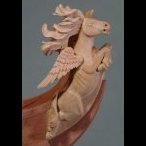
druxey reacted to DORIS in ROYAL CAROLINE 1749 by Doris - 1:40 - CARD
I have also created other crew members - a midshipman and one of the officers:
-
druxey reacted to NBP in Bismarck by NBP - 1:100
Hello some more updates
they are images from hull construction and crane, rangefinder, gun mock-up study model etc.. enjoy
-
druxey reacted to von stetina in Lightning by von stetina - 1/96 - extreme clipper
I'm putting on the mizzen shrouds. Donald McKay used a sort of extra mast top, or preventer top a bit below the mast tpps on some of his ships. It must of help negate the twisting forces. It must have added a lot of strength. There are so many things like this about some of his clippers. One other is that some of Lightnings biggest sails had an "X"shaped canvas bracing on them going from corner to corner.
She had an unusual mast/yard set up, she was very wide rather than lofty. I believe that he was trying to gain power this way hoping it would keep her from heeling overly much, making her a drier ship for the passengers. It was regarded as A very dry ship, so maybe it worked, even though the James Baines company of Liverpool added to her height. Their messing with McKay's design really irks me,. No wonder they were called wood butchers.
I left each shroud piece with plenty of extra length. The back halves of the preventer tops should have been put on later as they interfered with making the shrouds top eyes as tight as I wanted. I had to test each one to see that it cleared.
I used #80 Egyptian cotton for the seizings. They were started by passing a needle through to top of the eye. The needle had to be made sharper and with a longer taper. I then seized the shroud pair to their deadeyes. I put enough tension in the line to just see my mast starting to pull out of line. After all the shrouds were on I put on the mizzen forestay. Same type of tension.
Shown are some of my rigging tools. A paint brush handle with 1/2 of a safety razor blade glued in cut the thread like it's not there.
The flush cutters cut the finest thread cleanly, better than scissors. They are Lundstrum brand. After wearing out several Xuron flush cutters I sprung for the good ones. Expensive but worth it seeing how fast the others wear out.
As you see the main shrouds going in you can realize why I'm working stern to bow. You can't get the foresays in otherwise.
Bruce
-
druxey reacted to Mirabell61 in PAMIR 1905 by Mirabell61 - FINISHED - 1:96 - four-masted barque as she appeared since 1951/1952
Build log part 11
fixed a spring loaded steering chord strummer, adjustable spanning device
the steering (tin galvanized steel chords) come down from aft the highdeck and are guided over the aft welldeck, through the first two Bulkheads of the poopdeck, to where the spring is attached
in the Center keel "spine" (in Picture starbord of the spring) the 8,5mm hole-notch for taking up the 3rd mast safely, can be seen
the steering device leads into the highdeck wheelhouse in covered square protections
and is guided on along the aft welldeck
These are the two Long vents, they are still removeable and swivilable like all vents
somehow the Pamir Needs to steer, so here Comes the Balance type rudderblade
a Little riveting to it.....
and here now starts the riveting and plating of the hull
more to that in the next log part
for those of you who had already watched the plating of my steamship "Heinrich Kayser" one would say.... as usual..
Build part 12 to follow....
Nils
-
druxey reacted to Mirabell61 in PAMIR 1905 by Mirabell61 - FINISHED - 1:96 - four-masted barque as she appeared since 1951/1952
Build log part 10
Holding rails and some portholes, deck and rim mounted to deckhouse
bunch of vents in all Versions and sizes
made some portholes on my own (just learn by doing)
Fixing doors and deck reinforckment brackets
Access ladder
this and the next two pics should have come earlier....(nobody is perfect)
doors and under deck vents in forecastle area
strong eyelets on portside to take on the shrouds and backstays tensile forces
Build log part 11 to follow
Nils
-
druxey reacted to Mirabell61 in PAMIR 1905 by Mirabell61 - FINISHED - 1:96 - four-masted barque as she appeared since 1951/1952
Build log part 9
now the Fitting out is slowly moving on
the deckhouses had to be metal plated and painted, portholes drilled, etc, allready because they are fastend to the well-decks from below, before the decks had been permanently attached. There is hardly Access to the deckhouses any more in that position
I trust not a gram of filler is necessary on the entire single layer planking, shall be nice smooth base for the metal plating
the deckhouses have rims for their own wooden small decks, and for supporting soldering on of the boat supports later on
The ventpost tubes for mounting the cargo derricks to become each an Access lader
Fitting in the stairs
here one can already imagine to what a fiddeling it shall turn out later on when belaying the mast-pinracks ( and the complete functional running rigging corresponds to the original ships rigging)
the Position of the catwalk supports must be carefully Chosen in order not to interfere with the later to be placed steering wire chords that run between These Supports and along the 2 aft welldeck Hatch rims and along the aft deck housing
the sleeves for the venttubes allow easy upwards removal for the ventposts for not desturbing during the build
self explaining....
Build log part 10 to follow....
Nils
-
druxey reacted to woodrat in Venetian Carrack or Cocha by woodrat - FINISHED - 1/64
Some progress. Keel, stempost and sternpost in place and bulkheads positioned..
Dick
-
druxey reacted to garyshipwright in Brook in the book "The Naval Cutter Alert" by P. Goodwin
Hi Robert. Do believe that the breeching rope should be going through the ring bolt the other way, so have to agree with the others, that the artest is just a tad wrong. Here is a photo of a page in Adrian B Caruana book, Volume 2, The age of the System, 1715-1815, which should set things right. Gary