


druxey
-
Posts
13,088 -
Joined
-
Last visited
Reputation Activity
-

 druxey reacted to iMustBeCrazy in Santos Dumont No. 18 Hydroplane 1907 by Greg Davis - FINISHED - Scale 1:16
Greg, do you have any evidence of a rudder? I can see what may be a rudder in the middle of the rear foil in the early version and perhaps aft of the hull in the later.
If I'm right about the early version the entire foil must rotate to turn.
I don't think the wheel was used for steering at least in the early version, I think the lever on the right was. It's too big for a throttle lever and a lever was how he steered his aircraft.
I think the speed was controlled by 'blipping' the engine with a kill switch on top of the lever, this would be consistent with aircraft through WW1.
-
 druxey got a reaction from daHeld73 in HMS Bellona 1760 by SJSoane - Scale 1:64 - English 74-gun - as designed
Whether or not the actual ships' dummy lights were glazed or not is uncertain. However, contemporary models all show glazing. Draw your own inferences....
-
druxey got a reaction from daHeld73 in HMS Bellona 1760 by SJSoane - Scale 1:64 - English 74-gun - as designed
Flush, Mark. Yes, the dummy lights fooled me years ago as well!
-
druxey got a reaction from daHeld73 in HMS Bellona 1760 by SJSoane - Scale 1:64 - English 74-gun - as designed
Yes, glass aft of the wood panelling. As for tapering planks see:
https://collections.rmg.co.uk/collections/objects/66299.html
Look at the upper edge of the black strake. There the tapering is obvious. Unfortunately, Steel and others don't mention this in their texts!
-
druxey got a reaction from daHeld73 in HMS Bellona 1760 by SJSoane - Scale 1:64 - English 74-gun - as designed
If I understand your question correctly, your issue is with the varied thicknesses of planking as you approach the outer counter timbers. I believe that the wale thickness diminishes as it approaches the stern to that of the planking between the wales. I think this is 3" in your instance. This partially solves the issue. Secondly, the outer light of the stern gallery is a dummy one, so is boarded in anyway. One will not see the plank ends here. I recall this being the only reasonable solution when I built Polyphemus, 64 guns of 1781, some years ago.
-
druxey got a reaction from daHeld73 in HMS Bellona 1760 by SJSoane - Scale 1:64 - English 74-gun - as designed
Nice to see another strake completed, Mark. Sorry to read of your skin issues. Hope all is well now.
-
druxey reacted to Kenchington in Norwegian sailing pram by Kenchington – Model Shipways – 1:12
Steps 36 & 37 (first metal parts) completed, Step 40 (display stand) advanced
While waiting for a chance to get serious with my replacement tiller, I have pushed ahead with other steps in the build. For one, the pram needs an eyebolt in the middle of the bow transom (for towing, hauling onto a trailer or whatever). The inboard end of that bolt bears a plate to anchor the lower end of the forestay. Although the instructions make no mention of it, the kit includes a length of brass rod pre-bent to form the eyebolt. It also has the rigging plate as one item on a sheet of photo-etched brass. The model-builder is required to cut off a short piece from a (kit-supplied) length of 1/16" brass tube, to serve as an imitation "hex nut". The cutting went easily, following a recommendation (found here on MSW, not in the instructions) to insert a 1/32" brass rod into the tube, then roll it under a craft-knife blade. However, I did need to bell the end of the tube with a jewellery reamer. That also came into use to slightly enlarge the bolt-hole in the rigging plate.
When ready for fitting to the model, the three pieces seem tiny:
The instructions call for the eyebolt to be set into a slight groove around its bolt-hole, thus sinking the bent end out of sight -- the groove to be formed by pushing the blade of a very small screwdriver into the wood. That didn't really work for me but I did bed the bolt down nicely, none the less. Getting the plate and the tube-as-nut over the end of the bolt was challenging, but mostly because of poor lighting and poor eyesight. Once all was ready, it just needed a drop of CA glue, then the "nut" pushed home, while keeping the plate aligned with the pull of the future forestay. A few minutes for the glue to set and the end of the bolt could be clipped off. All looks OK:
Next up were the two chainplates ("stay plates" in the instructions), inserted into the slots previously sawn in the inwales. I don't know whether oiling the wood caused the slots to close up or perhaps I was just too scared to saw far enough. Whatever it was, the slots were way too small. Once I accepted that and sawed them longer, the chainplates (photo-etch pieces identical to the one for the forestay) fit easily. The problem is with the kit-supplied nails. As other MSW build-logs have noted, Model Shipways should provide their 0.7mm nails with this pram kit but they actually pack it with a supply of much larger nails, as in:
That's one of the chainplates (larger hole for the shroud, smaller for the fastening nail), with the kit-supplied nail above. No way that will go through the hole intended for it! To the left is an alternative nail that came with a rather nice Amati pin-pusher that I picked up at my local hobby store, but even that is too large. Below it is a 0.6mm nail from a supply I ordered in from Dry-Dock Models. (Those readers in the USA can go to the source and get extra nails from Model Shipways. I don't fancy the unpredictable delays at the border just now, with our respective governments edging into a trade-war!) The Dry-Dock nails proved OK in diameter but had to be clipped to half the length, lest they go right through the side of the boat.
Holes have to be drilled for the nails, of course. I thought that it would be a huge challenge to line up the nail (in its drilled hole) and the hole in the chainplate, while both were embedded deep inside the inwale. In practice, I pushed a mounted needle (i.e. a point set in a handle) into the drilled hole, used that to ream the hole out a bit, then jiggled the chainplate until the needle found the right hole. Pull the needle out, insert the stump of the nail, add a drop of CA glue, push nail home and all was well. Just needed a little bend of the chainplate to align with the future position of the shroud:
I tried moving onto the rowlocks (in Britannia metal) and the protective plates (photo-etched brass) that go on the pads seen in those two images. It proved too difficult without daylight, so that must wait for tomorrow.
Meanwhile, I have been pushing ahead with the display stand. That is needed sooner rather than later, as the model needs elevated support once the (projecting) rudder is in place. I'm still waiting on the weather, so that I can spray another coat on the baseboard but I have made up the supports:
The top pieces are kit-supplied and shaped to match the hull (needing only a little bevelling, after removing char). I decided to paint them, so that they are distinct from the boat itself. I toyed with the idea of a metallic finish but decided on less-prominent white. The kit includes a 1/4" dowel for the supporting pillars but the instructions suggest acrylic rod and I figured that would be nicer. Its also turned out to be very easy to work. Whichever material is chosen, there have to be slight flats where the wood supports fit over the rods. The acrylic yielded very easily to a file. After the first flat began to take shape, I laid it flat on top of a box, then worked the file on the other side of the rod, parallel to the box-top -- flipping the piece over every few file-strokes, until the supports just fit over matching, equal flats. I suspect that would have been much harder if done in wood.
A dab of CA and tops were glued to rods. They do need a little care to ensure that the horizontal axes of the tops are perpendicular to the length of the rods.
One annoyance yet to be faced is that the laser-cut holes in the baseboard are much larger than 1/4". As I have some adhesive-backed metallic-copper tape on hand, I am wrapping enough of that around the bottom end of the acrylic rods to make a firm push-fit. Most will be out of sight, down in the baseboard, but I'll add a final neat turn to give a flash of colour. That, however, must wait on the weather for outdoor spray painting, then the fitting of the supports to the baseboard.
Still have to do the tiller etc. (Step 35), the rudder, with its metalwork (Steps 38 & 39), the oars and rowlocks (Steps 45 to 48 ... the first of two "48s") -- and then it will be on to the sailing rig (Steps 42-44, 48-57).
Trevor
-
druxey reacted to trippwj in Nautical and Model Building Resources
In the nine years since I last updated this post I have acquired a few new resources - print and digital. Attached is a new 168 page update to my available reference works - some 2,500 give or take. I hope this may be of use to some of you.
All the best!
2025-03-29 Library of Wayne Tripp.pdf
-
druxey reacted to chris watton in Chris Watton and Vanguard Models news and updates Volume 2
Working area not much bigger, 1016 X 610mm compared to the 960 x 610mm of my current machine. However, that extra length does mean I can put 12 x 100x500mm sheets on the bed, rather than 10 sheets, plus I won't have to cut off 50mm off the ends of my larger (1000mm long) sheets to get them to fit.
Current machine is an 80 Watt Sealed CO2 Laser, whereas the new one is 100 Watt (my first one, which is being part exchanged for the new one, is only a 40 Watt and a 635 x 458mm work area, so no good for Indy or Surprise, but got me started and it did cut the first few kits fine, if a little slow...)
-
 druxey got a reaction from Keith Black in FULMINANT by HAIIAPHNK - French stern castle
Like many of us, you wish for a 'way-back' machine to see how it actually was. All we can do is make an educated guess.
-

 druxey got a reaction from HAIIAPHNK in FULMINANT by HAIIAPHNK - French stern castle
Like many of us, you wish for a 'way-back' machine to see how it actually was. All we can do is make an educated guess.
-
druxey reacted to HAIIAPHNK in FULMINANT by HAIIAPHNK - French stern castle
But let me add a late afterthought and adjust my own words.
On one hand, this can be seen as a curse. But on the other, it is also a blessing. Each of us has the joy of being not just a copyist but a creator.
Consider models of modern ships or battleships. If someone places the wrong gun or designs the bridge differently, it would be a mistake, a flaw. But we, in contrast, have the fortunate opportunity to be architects of our own vision and make our own choices.
-
druxey reacted to HAIIAPHNK in FULMINANT by HAIIAPHNK - French stern castle
Hello.
If I understood your words correctly, you want to contrast two perspectives: on one side, strict historical accuracy, and on the other, an aesthetic approach that may not always align with historical criteria or pragmatic logic.
That is an interesting question. I did not quite understand the mention of the fictional literary "Unicorn" as an example. Perhaps there is a meaning here that I failed to grasp correctly, or maybe it requires an understanding of the French way of thinking?
In my imagination, this is somewhat like discussing the intricate details of a specific submarine’s construction while simultaneously reading about Jules Verne’s Nautilus.
In my younger years, I loved exactly this kind of reflection, sketching the Nautilus in my notebook or imagining what the Duncan might look like. Later, I drew space tugboats inspired by my favorite science fiction stories. But that is a completely different approach. Perhaps I simply misunderstood you.
On the other hand, reflections on aesthetics are not limited to fictional ships. When I examine Bérain’s drawings, I have just as many questions. Where does his imagination take over—where something simply could not exist in reality and must be altered? And where am I obliged to stay as true to his style as possible, making every effort to ensure that his artistic vision remains intact on the model ship?
Well then, let’s try to follow this thread together. Where can we discuss the decoration of Fulminant, particularly its windows, as an aesthetic element? And where must we consider pragmatic logic?
Let the duel between real and false windows begin!
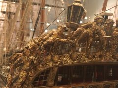
Before we start the discussion itself, I have taken a step to make things clearer. I have numbered the windows in Bérain’s drawing to spare both myself and you the agony of explaining which window I am referring to at any given moment.
First, let’s break down the fundamental question: what is aesthetic beauty? After all, everyone may perceive it differently. What, in this case, can be considered a more beautiful appearance? I would assume that a real window with glass is perceived by the eye as something authentic, whereas a false window forces our brain to think of it as a mere imitation—something of lower rank and lesser value and beauty. This is a very brief description and can easily be challenged. But if we were to dwell on this point for too long, we might never move forward.
So, I will state a debatable thesis: real windows are the more aesthetically pleasing option, and they look better than artificial false windows. And if we disregard all logical and pragmatic considerations, looking at this question solely from the perspective of aesthetic beauty, then we would want all windows to have real glass.
Now, let’s go through each window and consider whether glass can be installed there. I propose we start with window number 1.
This window is located on a nearly flat structure that imitates the upper part of a tower, positioned almost on the outer hull of the ship. This does not prevent it from being a real window with glass. Remember, we are not thinking about military concerns—only aesthetics. But is it that simple? No.
The problem is that window #1 is much higher than the transom windows and is positioned in such a way that it intersects the deck level between floors. If it had glass, it would look not aesthetic but rather absurd. So, this window can only be false. We have already dealt a blow to the aesthetic approach.
Let’s move on and examine windows #2, #3, and #4. These windows are on the hanging structure, meaning there is no issue with them intersecting deck levels. Technically, all of them could be real glass windows. But even here, there are questions.
What kind of questions? Let’s look at window #4. Imagine it had glass—what would we see? The window would face a wall. This reminds me of the TV show Friends, where multiple windows face brick walls of neighboring buildings. In contrast, Joey’s window looks straight into his neighbor’s apartment, allowing them to shake hands across the gap. I always wondered why someone would make windows with such a view. In the show, the point was to emphasize that the characters live in a cheap, budget-friendly building—one where students and retirees reside, in a cramped neighborhood where buildings stand close together.
Tight spaces do not convey wealth or high status. Yes, we could say much more here. We could note that this is a toilet window, that we are discussing the 18th century, not modern times, and that simply having a private toilet already signifies an officer’s high rank—unlike the hundreds of sailors exposing their bare backsides to the sea winds on the open latrines. But still, a window facing a wall is not the most aesthetically pleasing solution. So, it would be much simpler to make this window false as well.
And once we make that decision, we trigger an artistic principle: human perception is naturally drawn to symmetry. We instinctively seek balance, and asymmetry is often displeasing unless counterbalanced by other artistic elements. This principle applies here too. Windows #2 and #3 could easily be real glass windows, but for the sake of symmetry, it becomes tempting to make the left-side window false as well.
Does this mean that, out of all the windows, only one can remain glass? Yes. But even that is not a final decision.
At this point, it becomes a torment for anyone who loves aesthetic harmony. The human artistic sense will keep focusing on that single glass window, feeling that something is off. Everything else is false, so why is this one real? What is the reason?
A casual observer walking by will not know the technical justifications we just considered. They will only see that something feels unbalanced. Then, should we simply cover all the windows with wooden shields? But this raises the same question—why are all the windows false? No matter what choice we make, the sense of aesthetic beauty will still be dissatisfied.
In the end, my inner aesthetic sense led me to the conclusion that all the windows on the side castle should be false, except for window #3, which should have a small glazed vent to let light into the toilet. This way, the officer would feel more at ease, without worrying about sailors on nearby ships watching him struggle after a hearty meal.
We agreed not to consider pragmatic concerns, so I did not include military factors here. I did not mention that this is a warship and that glass windows come with drawbacks. I also did not discuss the fact that there was likely another cannon behind window #4, making it necessary to have a solid wooden panel instead of a glass frame.
Nor did I introduce the topic of non-transparent glass, which could let in light while concealing the officer or the wall behind it. But adding this discussion would only make the post even longer.
Conclusion
What final thought can I offer?
I believe that even if we start discussing windows solely from an aesthetic perspective, we inevitably return to pragmatic reasoning. These topics are too interconnected to consider one while ignoring the other.
And the solution? The solution remains open-ended.
Perhaps that is why we see models of the same ship built with different approaches—one modeler deciding on one execution, while another chooses a different path. Until we find actual photographs of Fulminant, L'Ambitieux, and other ships, we are doomed to keep asking the same questions over and over again.
-
druxey reacted to AntonyUK in Tally Ho by AntonyUK
Hi Keith. yes I have seen them. poor health ETC. Shame as I liked the Little pancho and the Forklift.
I have never Not finished a model As yet... but Age and health .. Who can tell.
Regards AntonyUK.
-
druxey reacted to Keith Black in Tally Ho by AntonyUK
The Tally Ho journey has been an important part of my life from the first episode. I've followed a couple of MSW Tally Ho builds that have come to naught. I hope you're more successful, Anthony.
-
druxey reacted to AntonyUK in Tally Ho by AntonyUK
Good evening.
Greg. Im'e sure he would if he was still in his workshop. I liked the choice of timbers he selected for the rebuild.
Keith. Pancho has been a part of Tally Ho from the beginning. along with the hens and the dog. Always nice to see.
Jim, Jerome. I like the lines of the boat and its a easy to model as the drawing have all the information needed.
Just sourcing the Polyisocyanurate boards. local supplier calls it Celotex. Must be this type of foam so it can be laminated with any resin without dissolving.
Then on with the fill between the frames.
Thanks for looking.
-
druxey reacted to dvm27 in Tally Ho by AntonyUK
Love Leo's build and yours as well. I'll bet if you e-mailed Leo he would send you a piece of timber you could incorporate into the hull. I have corresponded with him in the past and he is indeed as nice as he seems
-
druxey reacted to AntonyUK in Tally Ho by AntonyUK
The boat Tally Ho.
I got interested in this cutter from a YouTube series by Leo.
https://www.youtube.com/@SampsonBoatCo/videos
Followed the build all the way through. Leo is a Boat builder and sailor. (His words)
Started on this boat in August 2024 by ordering a set of plans from the Albert Strange Trust https://albertstrange.org/
I decided that the model should be :- 1000mm at the waterline and 1173 from Stem to Sternpost and a 287 Beam.
I used Fusion360 (Home hobby version) to bring the 2D plans into 3D which took me till December.
My son purchased a Laser cutter for me as a Christmas present. 22 watts and a cutting bed area of 410X400.
Then it took me 2 months to learn how to use it and to set it up in my shed with a Ventilation extraction system.
The software I used was Shaper Origin Addon in Fusion. to export the .svg file to Inkscape. And then into LaserGRBL for the cutting interface to the Laser cutter.
The Stem Sternpost Deadwoods are 16.6 timber. They were marked by laser engraving a line onto the timbers and band sawing the parts out. They were finished to size using a Proxton mini mill to square and split the laser line.
The Bow and stern sections were assembled and checked and glued.
The Keel was made up by using a bread and butter construction method. The layers were cut on the laser using 4.2mm pine from my local DIY store. I had 4 dowel pin holes along the length of the keel to ensure the straight and true alignment.
Dry assembled and checked for length shape and alignment. All good so on with the gluing.
The frames were laser cut using 6mm laser ply. This was my first real cutting with the laser.
The Bow Stern and keel were glued and pined together. Wow this is going to be a BIG model.
I also designed a Jig to build the boat on fusion to help with the alignment.
Building this boat inverted as it best for me. The keel and Stem and Stern post were added to the Jig then the frames were placed in place on the jig. Everything looked spot on so i glued them together.
Small bits if off cuts were added between the frames to maintain the correct frame spacing.
Now we are up to date with the build as it is now.
Next week.
Going to fill between the frames with 40mm insulation foam boards. This will provide me with something to fare the frames and to lay fibreglass onto.
Not done any fibre glassing before so ANY advice would be helpful.
Regards AntonyUK.
-
druxey reacted to Louie da fly in Mary Rose by Baker - scale 1/50 - "Your Noblest Shippe"
I agree about reducing the height of the upper part of the forecastle. It looks better that way. And yes, red, white and yellow stripes. The colours on the Anthony Roll are a bit difficult to interpret, but certainly not green and white as shown in the modern picture. Guns and carriages look great (Henry the Staffy's a real gem!) and the ladders are spot-on.
Nice work (as usual!), Patrick.
Steven
-
 druxey got a reaction from mtaylor in False keel: Admiralty orders concerning coppering
This order makes perfect sense as the false keel is sacrificial. Thank you for this, Bruce.
-
 druxey got a reaction from Harvey Golden in St Roch by Lecrenb - 1:48 scale - RCMP Schooner rigged as schooner c. 1930/35
Nice attention to detail! Chart cabinet looks very convincing.
-
druxey got a reaction from daHeld73 in HMS Bellona 1760 by SJSoane - Scale 1:64 - English 74-gun - as designed
Lovely result, Mark. Aren't those planks fun? Folk think that topside planking is just straight parallel strips of wood. You know better. Well done.
-
 druxey got a reaction from thibaultron in False keel: Admiralty orders concerning coppering
This order makes perfect sense as the false keel is sacrificial. Thank you for this, Bruce.
-
druxey reacted to ccoyle in Mitsubishi A6M5a Rei-sen by ccoyle - FINISHED - Halinski/Kartonowy Arsenal - 1/33 - CARD - Allied code name "Zeke"
The usual robust framing in a Halinski kit, this time for the aft fuselage. The tail wheel well includes a piece with the interior color.
And now for a bit of news: This build will be going on a temporary hiatus. I know I already have another kit on hiatus for this build, so I guess that makes this a hiatus²? 🤔 Anyways, I will be building WAK's SBLim-2A, which shouldn't take too long to build (hopefully). A build log will be created for that shortly.
Cheers!
-
druxey reacted to ccoyle in Mitsubishi A6M5a Rei-sen by ccoyle - FINISHED - Halinski/Kartonowy Arsenal - 1/33 - CARD - Allied code name "Zeke"
The forward fuselage has been added. This cylindrical section was quite a booger to shape properly. You can see there is a small gap along the left-hand white part labeled 'WPS' -- fortunately, that stands for "cut out after gluing," and that is where the machine gun channels will be added, so the gap will magically disappear. Forward of this (which comes later in the build) will be interesting, because next there is a bulkhead that supports the cowl, and the kit's paper exhaust pipes are supposed to be glued directly to this bulkhead; the 3D-printed pipes are longer and should ideally pass through this bulkhead and attach to the cylinder heads. I will need to do a lot of thinking about how to make that assembly work.
The next assembly according to the parts numbering is the aft-most fuselage section where the tail wheel well is located -- the fuselage is thus supposed to be built back-to-front. Not sure why that is, but I will probably build up all the sections first just to play it safe, then assemble them together in the correct order. First up is the section right behind the cockpit. Right now I am letting everything set after gluing the ring together and soaking the bulkhead in thin CA. I've punched a couple of holes into the bulkhead so I can manipulate it with round-nose pliers.
Cheers!