


John Maguire
-
Posts
157 -
Joined
-
Last visited
Content Type
Profiles
Forums
Gallery
Events
Posts posted by John Maguire
-
-
Brian,
Thank you for that info. Could you please describe the tick strip method?
When you adjusted your thread bands did you try to maintain a constant distance between them?
Do you consider where your drop planks, spiles and steelers when you are making the bands wider or narrower?
Thank you,
John
-
Thank you for the many "Likes" . . . .
May I respectfully ask for an opinion by some of you who are experienced with planking? As previously stated, I am trying to learn how to line out my hull. Having read your many accounts but never done so myself I want to gain experience by practicing on the first planking so that I have a little more experience when doing the second. I recognize at least three techniques. Antscherl suggests defining the bands with threads and moving them to make the plank flow look pleasing to the eye. Another method suggests using battens of the intended planking material. Yet another maps the dimension of each frame and creates a "plank list" with intended widths of each plank at each position on every frame. So far I have lined out samples of the first two techniques. I have made no attempt to map - yet.
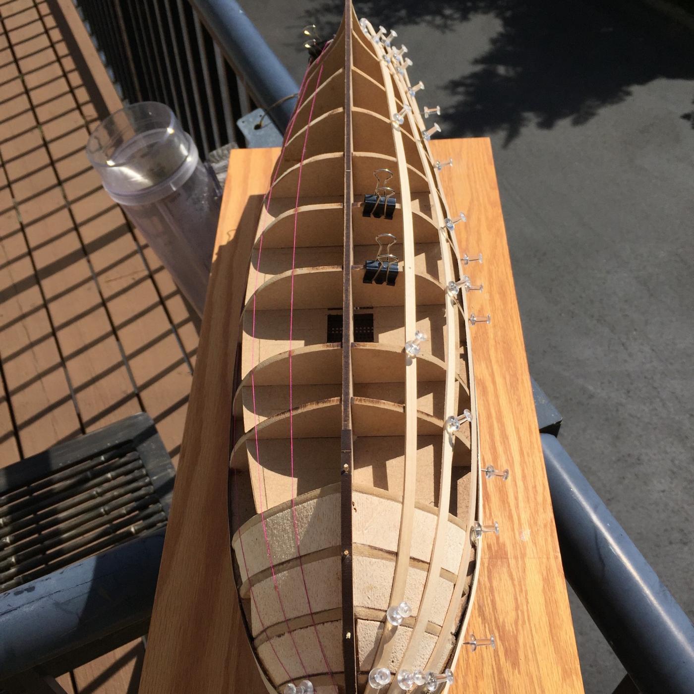
The first step I took was to lay five planks adjacent to the keel at midships and mark their cumulative width on several frames. The paper clips show where I made that initial measurement.
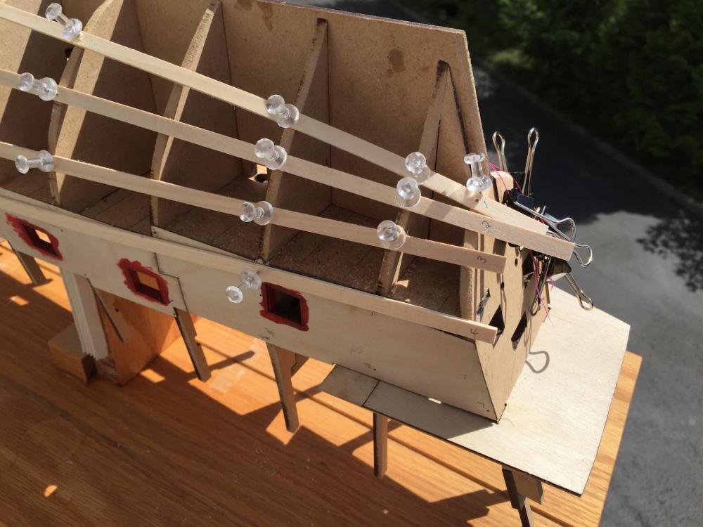
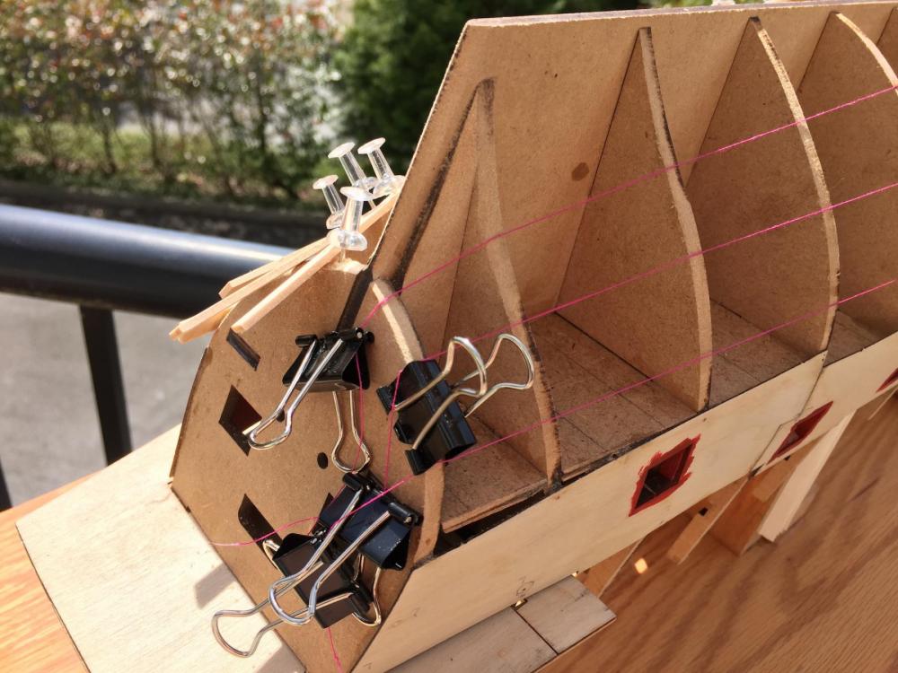
Next, using that measurement I laid out thread on one side of the hull. On the other side I laid several battens taking care to allow each to follow its natural lay - in other words, only bending to the frames.

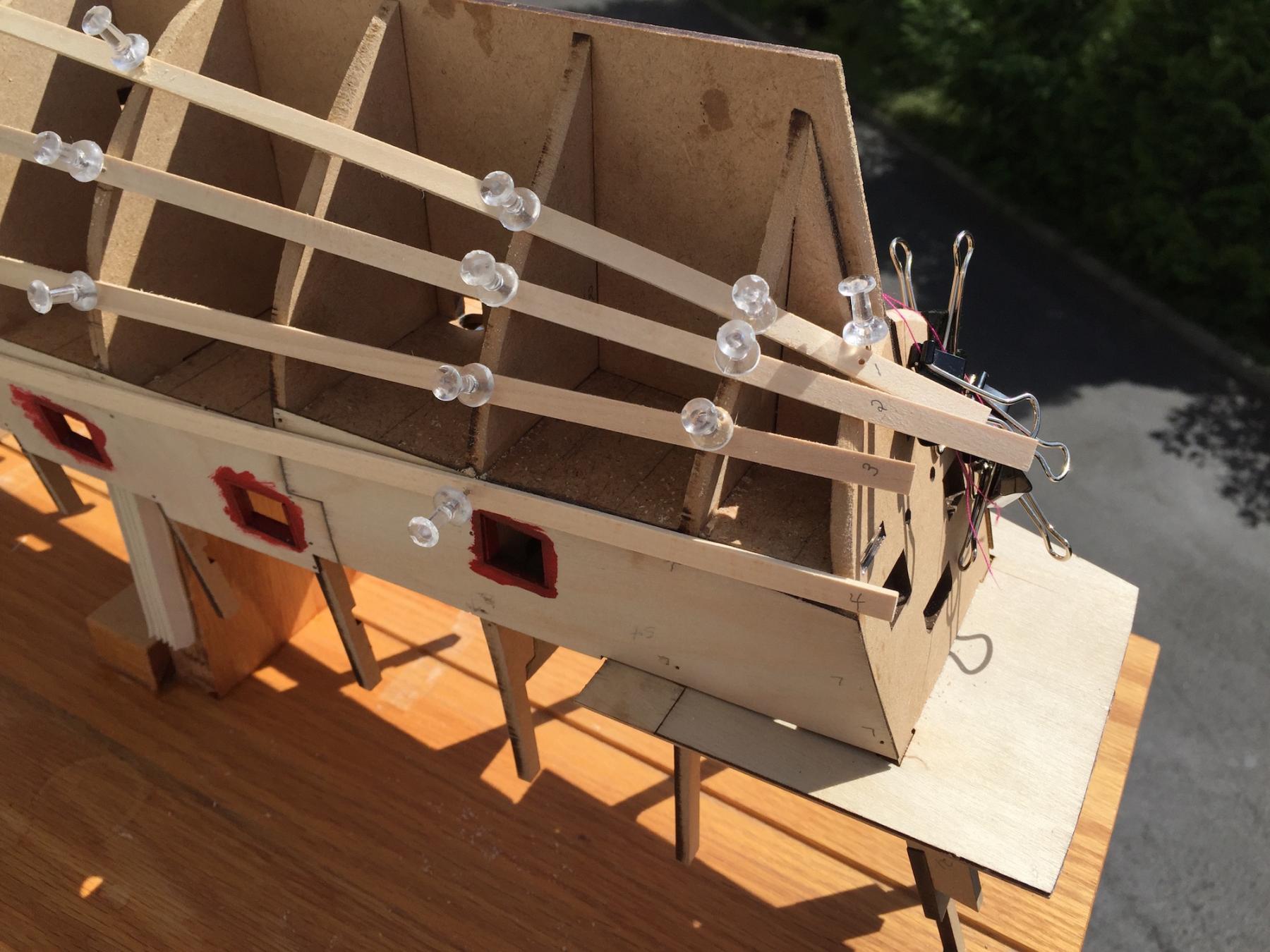
Battens laid flat against the frames produced what I believe to be an unsatisfactory result at the stern.
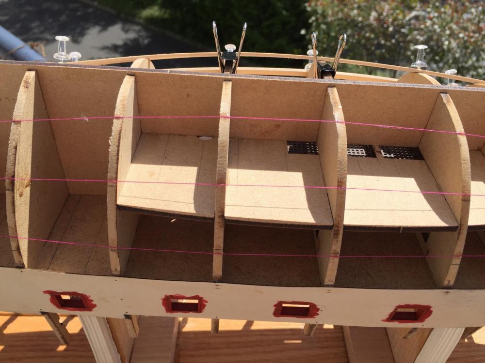
Threads run in a manner that looked somewhat reasonable to my eye looked like this at the stern.
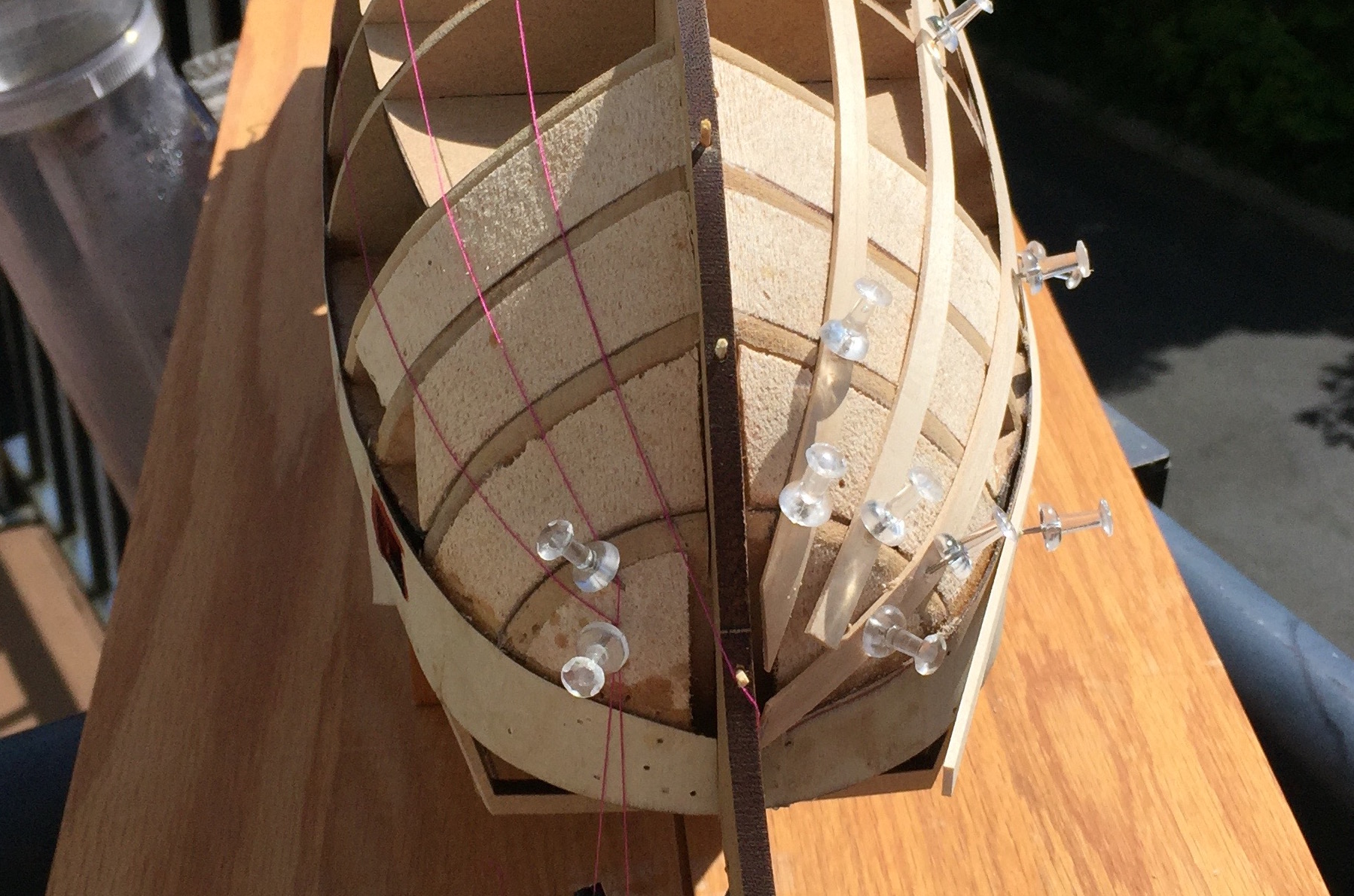
The bow looks like this.

It appears to me that neither technique is working well. I feel like the use of battens should be ruled out - horrible need for dropped planks AND steelers at the stern.
The threads might be moved around to achieve a reasonable appearance.
Will I do well to get a little more technical and create a "plank table" that shows how wide each plank should be at each position on every frame?
Thank you for your time looking at this series of questions.
Respectfully,
John
-
-
-
-
Thank you dear friends for the "Likes".
David, yes, the ply panels had both horizontal and vertical curves. While very thin it was surprisingly stiff. During the dry fit I experimented with suitable fasteners to ensure a tight fit in both planes. My locator holes were marked so once the glue was applied it was easy to get the pieces where they belonged. Sixty minute epoxy was used to allow ample time for adjustment. I am satisfied with the result.
Brian, thank you for checking in. I am most pleased to welcome you aboard and look forward to checking out your own projects.
Doc, thank you for commenting. I continue to be in awe with your build.
Denis, yes, liners would not work for the small cannons fore & aft but to my eye are suitable for all the mid ship positions. I believe I'll like their appearance when the final planking is applied.
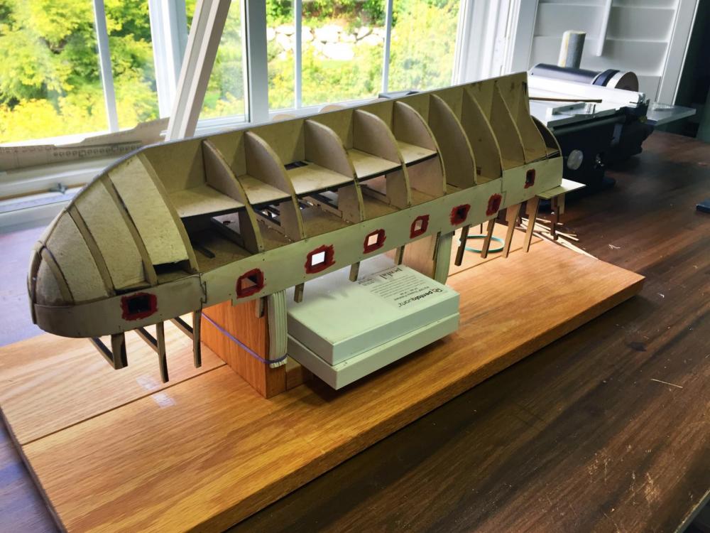
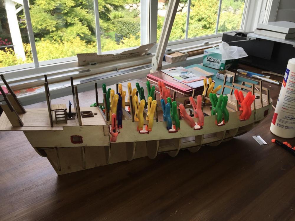
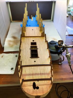
All the intended liners are in position and painted now.
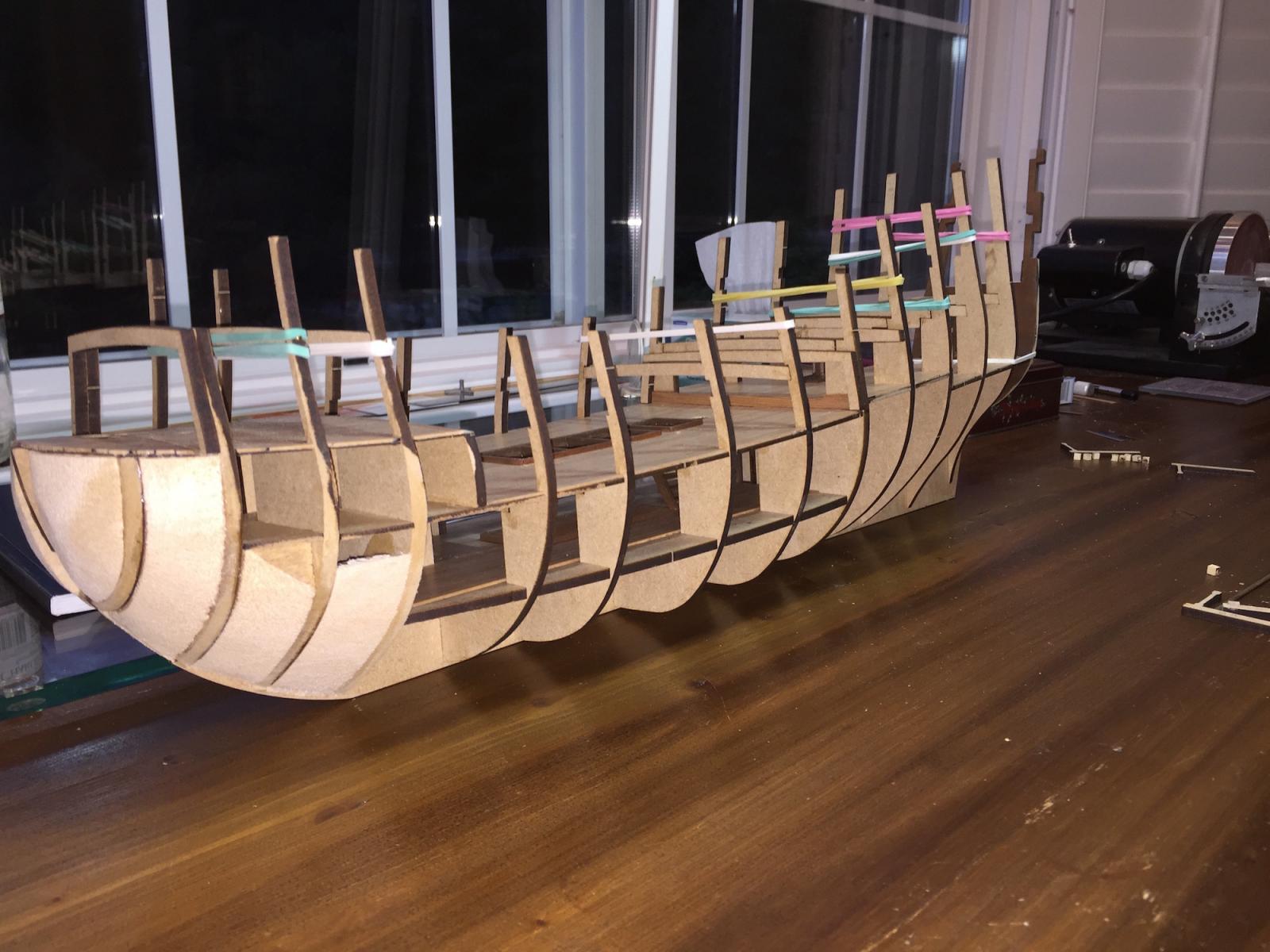
As I've seen others do in similar circumstances I have constructed a mount to hold the hull securely for planking and used soft ribbed rubber strips on the edges that are in contact with the ship.
I have a days tasking to make minor adjustments in the stem area, recheck fair lays, then begin the first planking. With no planking experience but having read the work of dozens of the rest of you and also studying many different techniques I plan to approach the first planking with the attitude that it is the final planking. Clearly, reading about it and doing it are vastly different. I want to do this so that my final planking with good wood and that I want to look nice isn't in point of fact my first attempt.
To that end, when I do the first plank layer I plan to use David Antscherl's dissertation and line off the hull in a suitable number of five plank bands. I'll do the same for the finish layer.
Can there be a suitable reason to not go slowly and learn?
Respectfully,
John Maguire
Cougar Mtn. Shipyard
PS: two of my other hobbies (ham radio and bikes)

-
-
-
Thank you dear friends for the "Likes".
Yes, Denis and Doc, it was PVA glue. As you both suggested I went back in with two part epoxy. Excellent catch - thank you.
I am interspersing this project with another so progress is a little slower. Also, there were many construction steps that required a day each for glue to dry.
I taped the various ply panels together, then, as a whole, they were manipulated for what seemed like the optimal position and pinned in place. The appropriate pin holes were subsequently used to locate and glue the appropriate sections into position.
Selective clamping of six individual ply panels while applying glue necessitated multi day drying - glue - a day to dry - glue - a day to dry, etc . . . about a week to glue the six panels.
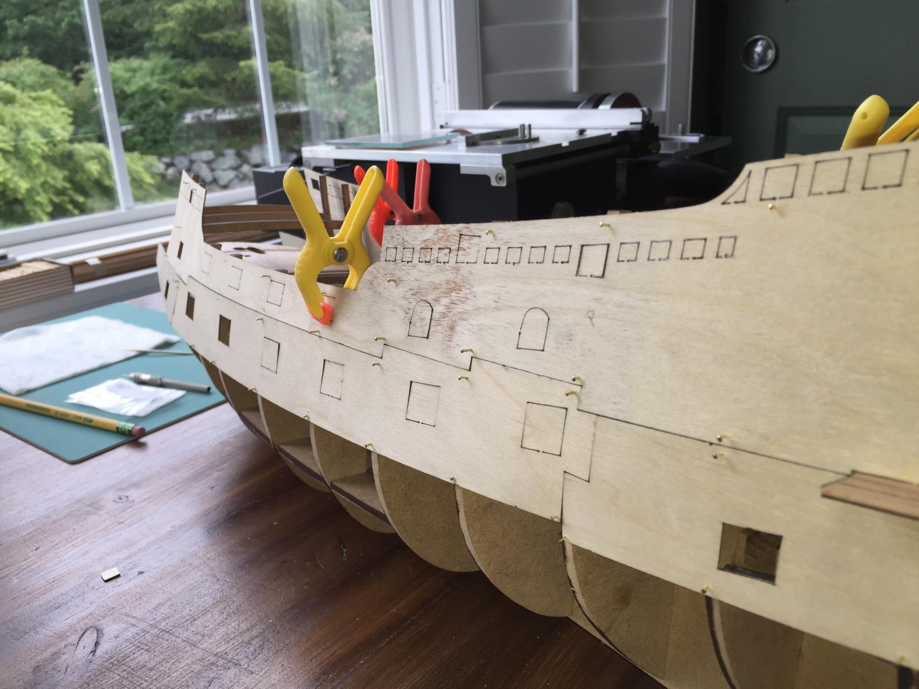
After permanently attaching the panels the gun ports are seen here clamped in place.
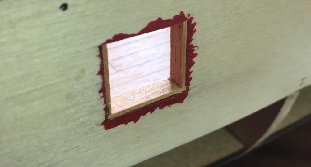
I am adding liners to the gun ports. They overlap the ply so that when the planking is applied the ply edge won't be seen. This is the first one, unpainted, seen in a test fit. All the others liners are already fabricated and will be installed and painted after the gun port glue cures.
Respectfully submitted,
John Maguire
-
-
-
I have been involved with other things for the past month with model building and forum reading on hold.
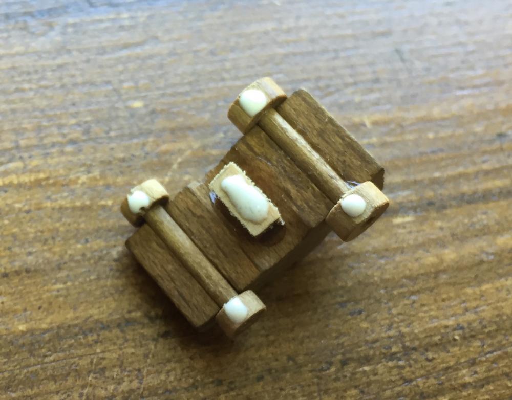
After completing required deck planking, hatch frames were placed, ladders built, some gun port frames attached and canon carriages mounted, all in sequence as called for in the builders builders manual.
I glued a block to the underside of interior mounted canon carriages in an attempt to insure they don't break loose.
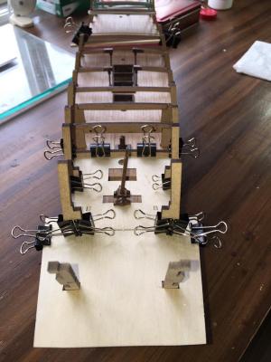
A couple of days were spent reading the builders manual and the two preexisting build logs in an attempt to correctly position the ply patterns. Once satisfied they have been pinned in preparation for glueing the lower sections. At this juncture, all are temporarily pinned in place to assure the overall correct positioning of all panels during subsequent construction.

Respectfully submitted,
John
-
-
-
-
-
Martin,
Thank you very much for taking the time to respond with so much detail. Yes, I study your build and Denis's thoroughly . Particularly as I move into new areas.
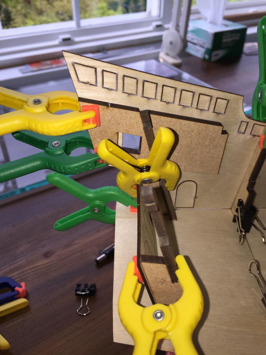
As I continue to study my situation I have found that part 20 and the corresponding thin plywood piece are each slightly different than what I see if I hold either of them up against the plans. However, when I fit them to the ship and align the plywoods lower notches to the the correct part of their respective frames, as shown on the plans, everything works out perfectly. That includes attaching the piece ahead of it that runs forward to the bow. With those two pieces of plywood butted nose to nose I end up with a small overhang at bow and stern - both the same. Therefore, I do not have a problem - it is simply that the plans and manual are slightly different than the kit . . . .
This all came about when I began to temporarily attach the ply wood as a guide for planking the rear transom deck I thought it prudent to see if other related things were going to come together OK later on. I didn't want to have a terrible surprise when it came time to attach the plywood permanently and discover there was a problem that couldn't be fixed.
I just looked at your time line from start to where you are at the moment and it shows a striking example of the time required of an experienced builder like yourself and me with no experience to speak of. This model is fascinating and I look forward to getting into it every morning.
Respectfully,
John
-
Doc; Thanks.
Two other folks posting build logs are ahead of me and I think I have seen indications that there are an additional two who are not posting. I hope to hear comments from them.
I can see what needs to be done but would like to hear from someone ahead of me who has possibly encountered this situation before I begin carving up a kit supplied component. There is always the possibility I am doing something wrong or overlooking something.
In point of fact I have a fair way to go before this issue would become a factor. I only discovered it by looking a long way ahead to verify fits.
Respectfully,
John Maguire
-
Trouble in paradise:
The modified center ship partial width deck beams went in satisfactorily. Two aft decks installed with perfect fits between the frames.
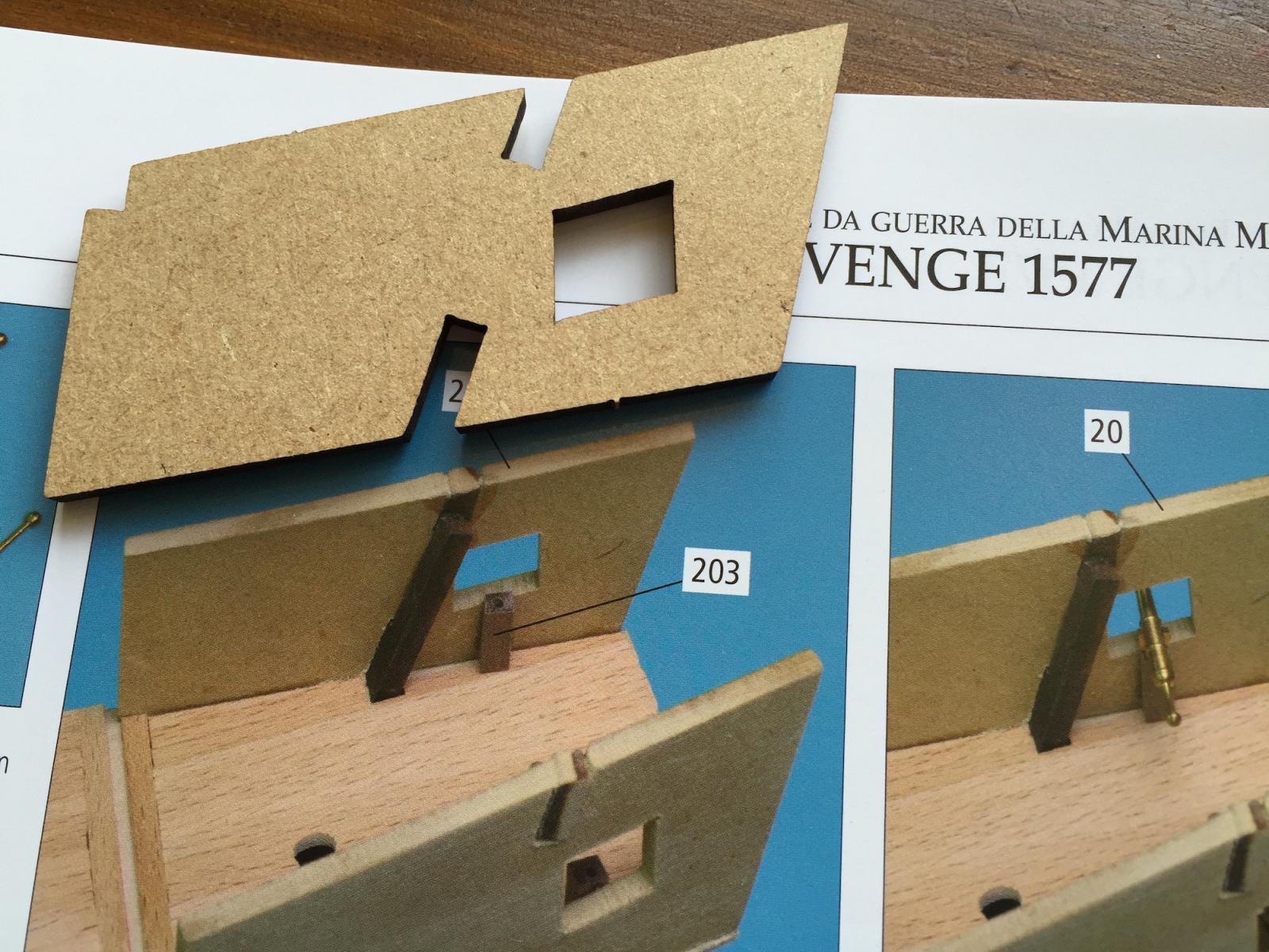
Part 20 shown in the manual is different than the one supplied with the kit. It might be construed from the photo that the cannon port is possibly further forward in the manual's photo than the part supplied with the kit.

This is the supplied part 20 held against the plans. Note the misfit of the cannon port.
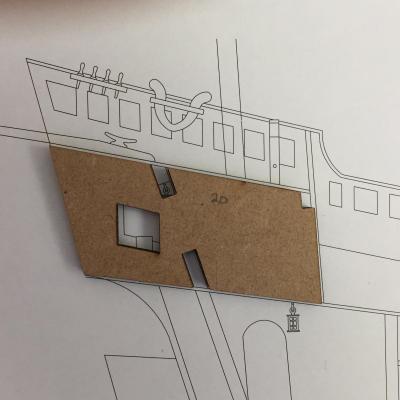
Look how the misfit on the model is the same as on the plan seen above. The doorway position shows that the plywood panel can not be shifted aft to accommodate the cannon port in the MDF panel.

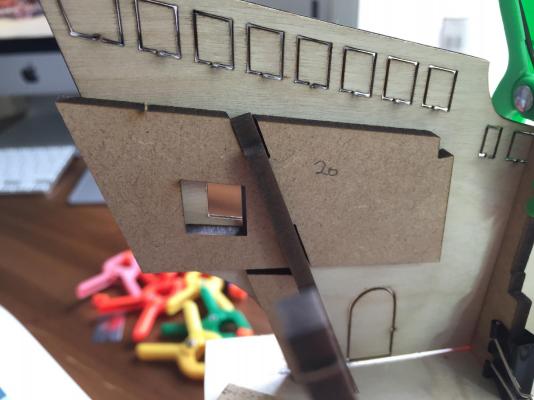
My initial reaction was that I have made an error with frame alignment someplace in the ship. To test that theory I laid out all the many plywood panels against the frames to see if when in place the aft, mid and the bow ends were in the right place - they are.
My initial speculation, based on the way that part 20 is wrong when overlaid on the plan - and that the photo in the manual shows a home made part 20 is that the supplied part 20 is incorrect and I'll have to modify it.
Possibly someone ahead of me can offer their experience.
Thank you for the many "Likes".
Respectfully,
John Maguire
Total time 137 hours
-
Mark, thank you. I never thought to go back to the Proxon page. I was thinking something of Sherline quality was called for. I am enjoying ver 2.0.
Nigel, your Confederacy is excellent. Ditto on Proxon - thank you. I eye balled the present 4mm block centers and considering where they will reside they are satisfactory.
Respectfully,
John Maguire
-
-
Thank you for the Likes . . . .
Yesterday the ladder and capstan were built and air brushed. This morning I glued them into position. All deck beams for the next level were fit and glued. The transom piece was tapered as necessary and finally glued into permanent position.

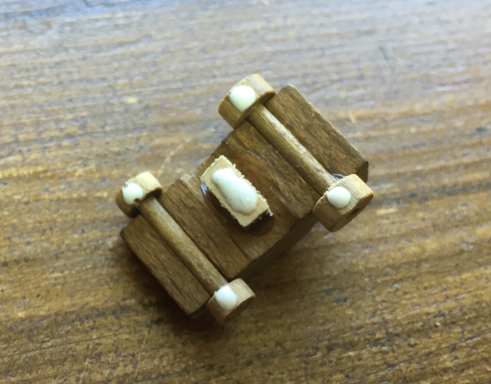
The midship deck beams are split for the open look down area to the deck below. The supplied pieces had rectangular columns and that didn't look attractive to me so I set about trying to sand the columns round - in this case, easier said than done . . . no good.
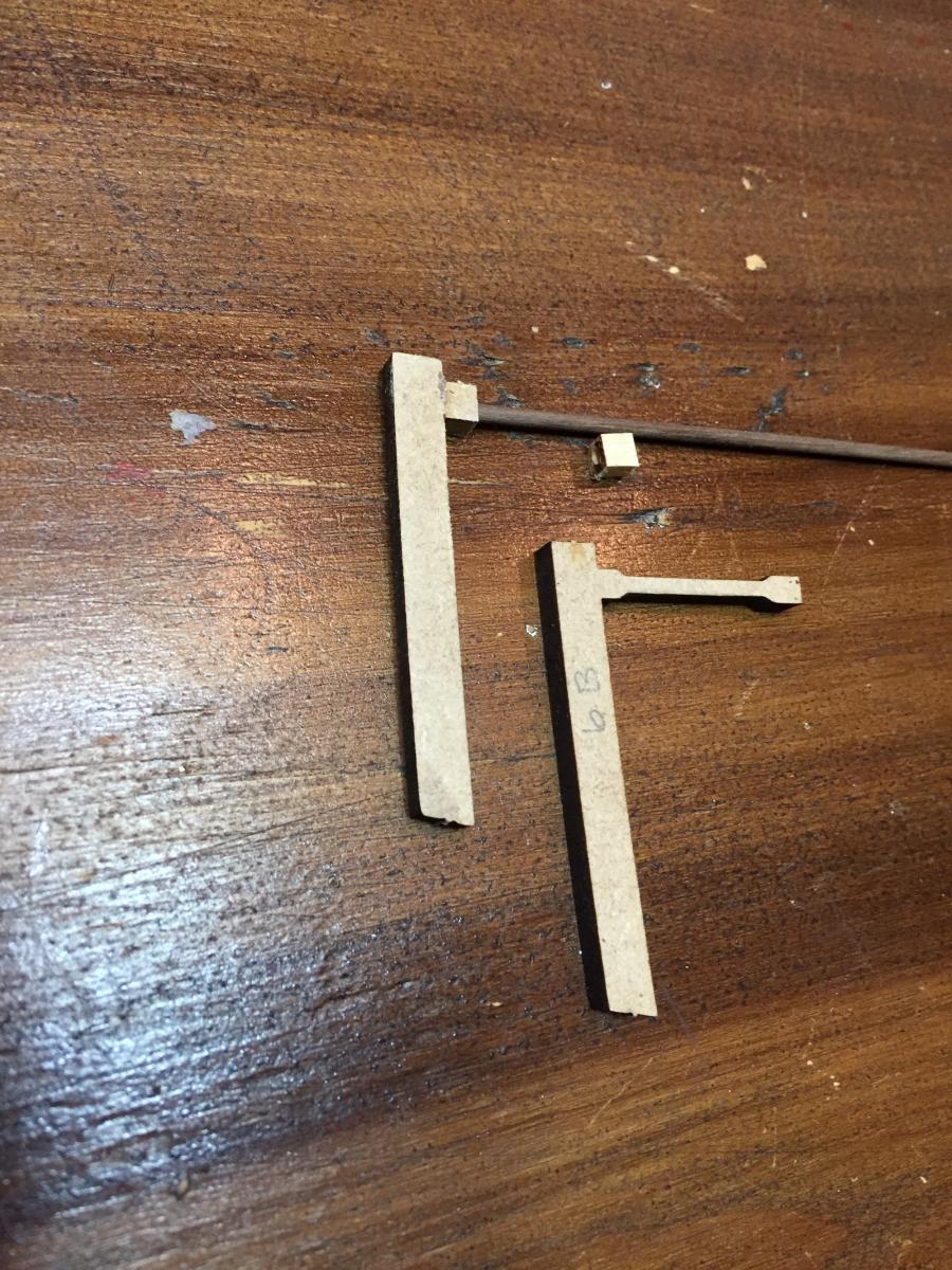
After an afternoon long aborted attempt to sand the MDF rectangles into a somewhat round shape I abandoned that and began to scratch build round replacements. Here you can see the original shape. In my modified piece I have cut off the complete column from the deck beam. Square pieces were made for the top and bottom of the column and 2mm round stock will be cut. The upper square column component is socketed for structural integrity and the bottom square portion of the column has been drilled completely through. That will enable me to fine tune the overall length of the column to the exact required dimension.
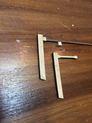
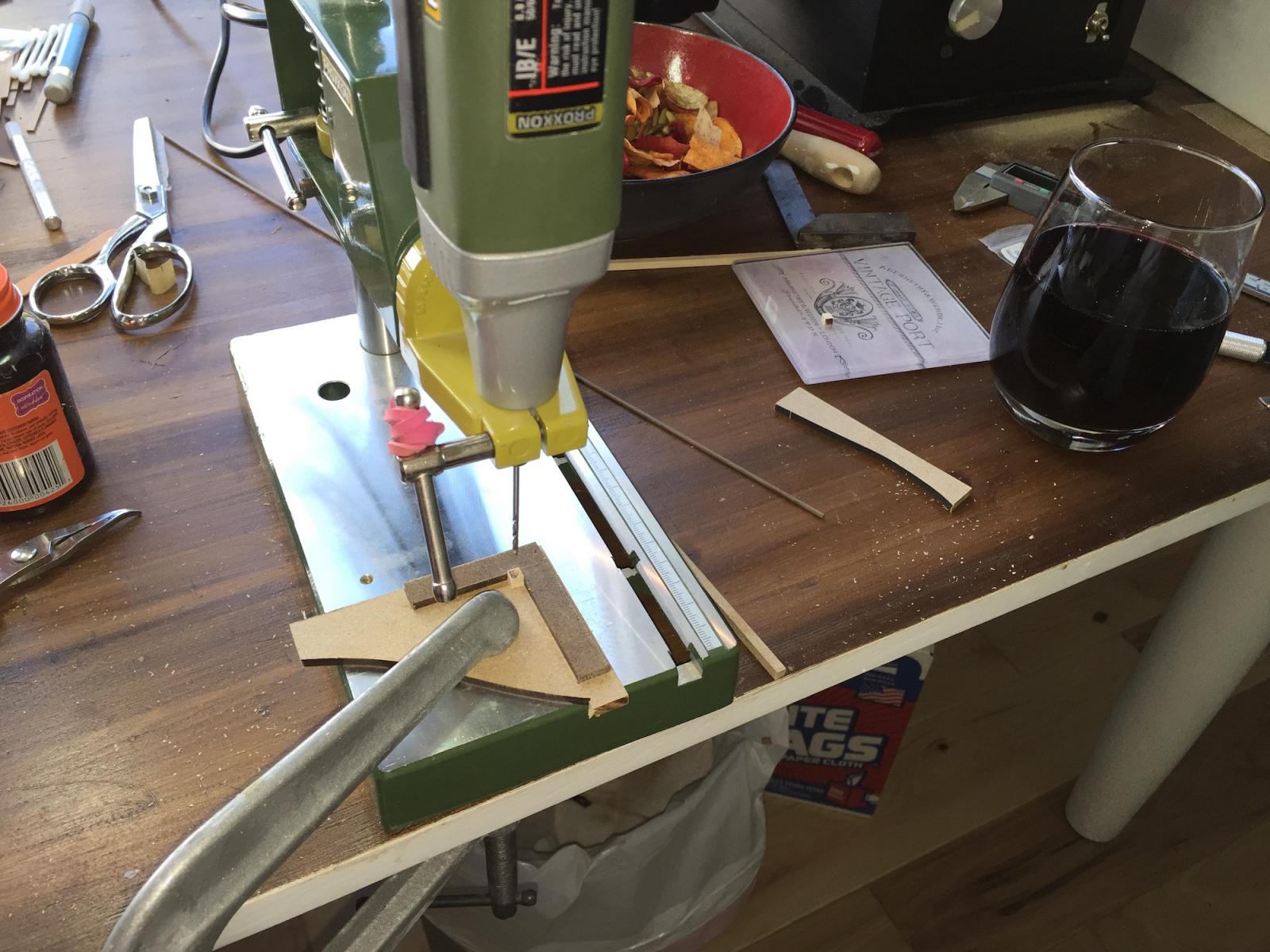
In order to capture such small pieces for drilling and furthermore to achieve a uniform result I made a jig to hold the 4mm cubes. I sure wish I had a better drill press and an X Y table. Is there such a thing for such small work?

Tomorrows tasking will be to complete the four columns, paint and install them.
With the next level of deck beams in place it is starting to look a little more ship like . . . .
Respectfully,
John Maguire
Total time 130 hours
-
Thank you for the many "Likes". It is nice to see you are all looking in.
Mark, thank you for looking in and commenting. I have now planned out in my mind how to deal with this, grateful that it was revealed in a timely manner.
Don, thank you for your effort on my behalf. What you describe is pretty much what I shall have to do.
Also, repeated viewing of the plans uncovered the required detail. After qualifying the deck hole a couple of days ago it is a sufficiently snug fit that I can temporarily put the post in place then during rigging reach down through the grate in the deck above, do all that is necessary with the grate cover and post then put all in place as necessary.
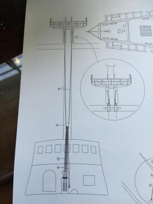
Yesterday was spent prepping and moving forward. I fabricated a vertical winch (forgot what it is called) and a ladder that the instructions dictate for installation at this point then got the paint booth out. Seen here is an overkill with the air brush - painting the stern post interior. Primarily I was using it for the smaller components mentioned above.
Respectfully submitted
John Maguire
Total Time 122 hours
- catopower, BLACK VIKING, mtaylor and 5 others
-
 8
8
-


REVENGE by John Maguire - Amati/Victory Models - build in the Cougar Mountain Shipyard
in - Kit build logs for subjects built from 1501 - 1750
Posted
Mark & Brian,
Thank you very much for your time. I do have all the guides from that web page already but it is in addition to other info and that ends up being so much that I wasn't sure which path to follow. Using wood battens and letting them flow "naturally" was one of the many techniques but as seen, that did not work for this hull shape.
I do like doing bands and will go in that direction. I will edge glue some planks when spilling becomes necessary.
How about plank length? This transom style lends itself nicely to using single length planks.
Respectfully,
John