


Pirate adam
-
Posts
247 -
Joined
-
Last visited
About Pirate adam

Recent Profile Visitors
2,300 profile views


-
 Admiral Rick reacted to a post in a topic:
In which offense is taken (or, "hey! I resemble that remark")
Admiral Rick reacted to a post in a topic:
In which offense is taken (or, "hey! I resemble that remark")
-
KARAVOKIRIS reacted to a post in a topic:
HMS Crocodile 1781 by Pirate adam - 1/48 scale - POF
-
That turned out really good. Very cool model. Adam
-
AON reacted to a post in a topic:
HMS Montague 1779 by garyshipwright - 74-gun Alfred-class
-
It is great to see an update. It is looking amazing. This model on the old site was one of the ones that showed me what is possible with POF models. Adam
-
yvesvidal reacted to a post in a topic:
HMS Crocodile 1781 by Pirate adam - 1/48 scale - POF
-
davyboy reacted to a post in a topic:
HMS Crocodile 1781 by Pirate adam - 1/48 scale - POF
-
ChrisLBren reacted to a post in a topic:
HMS Crocodile 1781 by Pirate adam - 1/48 scale - POF
-
albert reacted to a post in a topic:
HMS Crocodile 1781 by Pirate adam - 1/48 scale - POF
-
 Pirate adam reacted to a post in a topic:
HMS Crocodile 1781 by Pirate adam - 1/48 scale - POF
Pirate adam reacted to a post in a topic:
HMS Crocodile 1781 by Pirate adam - 1/48 scale - POF
-
westwood reacted to a post in a topic:
HMS Crocodile 1781 by Pirate adam - 1/48 scale - POF
-
gjdale reacted to a post in a topic:
HMS Crocodile 1781 by Pirate adam - 1/48 scale - POF
-
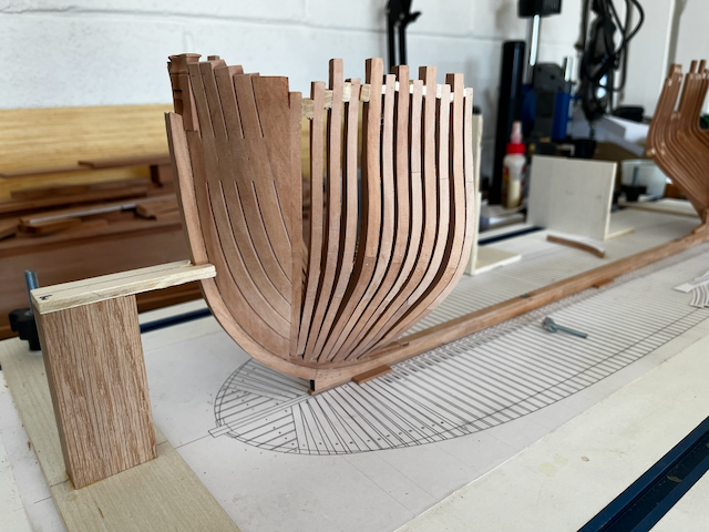
Finally some progress to report. All of the bow cant frames now complete. I re-made the hawse timbers, because I originally made them way too thin at the bottom so they didn't fair in properly with the cant frames. I somehow ended up with first pair of cant frames being too short. I'm not sure how that happened. I will just extend them, as it will be easy enough due to the wedge-shaped piece that butts against them. I can't wait to shift gears to the square frames. I will admit I was close to giving up so many times getting through the hawse timbers and cant frames. This was my first time drafting all the angled bits from the admiralty draughts, and the learning was painful. Next time should be easy, lol. The shape is pretty pleasing to see now that it is all together. Adam
.png.658c9cf19c873116f527c6b6a172c4ce.png)
-
In which offense is taken (or, "hey! I resemble that remark")
Pirate adam replied to Cena's topic in New member Introductions
Welcome. You should do a build log. There is an unbelievable amount of support and great advice on this forum. There is really no downside. Every expert was a beginner when they started. Adam -
I love the colors of the wood. It is a really cool look. Adam
-
I’m not sure I would buy an airbrush just for wood ship modeling, but they are certainly a wonderful tool, especially for painting on metal and plastic. My go to is an Iwata from Hobby Lobby combined with a regular garage air compressor equipped with a proper pressure regulator and moisture trap. I concur with Kurt that it is worth using the thinner recommended by the manufacturer despite the myriad other options people recommend. I agree with Kurt that they provide opportunities for effects that are very difficult to replicate any other way. There is a bit of a learning curve, but lots of videos on YouTube, etc. Adam
-
Kevin, I love every time you say “I just need to build the skill.” It is a great reminder that one of the cool things about this hobby is it involves mastery of so many different skills and almost all of them are pretty manageable with enough practice. Adam
-
Pirate adam reacted to a post in a topic:
Nate's PANDORA in 3D
-
Pirate adam reacted to a post in a topic:
Nate's PANDORA in 3D
-
Pirate adam reacted to a post in a topic:
Nate's PANDORA in 3D
-
Siggi, It looks amazing. I’m glad you were able to get it the way you want it. There is no point having a little detail that will make you dissatisfied whenever you look at the model. I love the colors. Adam
-
Nate's PANDORA in 3D
Pirate adam replied to 3DShipWright's topic in CAD and 3D Modelling/Drafting Plans with Software
Nate, The first thing that I came across was the number of transoms. The Anatomy of the Ship book shows 5 transoms. My shear plan of Crocodile shows 4 transoms. All of the other Porcupine class ship drawings I have seen also show 4 transoms. This is consistent with my interpretation of the tables in Shipbuilders Repository. The other point was the big difference between the various disposition of frames drawings I could find for ships in the class. The disposition of frames drawings for the Porcupine class do clearly show the diminishing timbers. I made the assumption based on the disposition of frame drawings that the frame bends had air spaces separated by chocks vs the Anatomy of the Ship book which shows the bends as adjoining frames. I will add this is a very interesting discussion. I don't have much to add in terms of debate. I am surely not an expert in naval architecture. It is clear we both started with a different set of assumptions going in which results in a different result in the end. As I said in my original post the fact is no one knows for sure. The most important thing is your 3d model is awesome, and I really enjoy every post. Adam -
Nate's PANDORA in 3D
Pirate adam replied to 3DShipWright's topic in CAD and 3D Modelling/Drafting Plans with Software
Nate, This is a topic I spent a lot of time agonizing over for my Crocodile build. I was planning to use the framing pattern straight out of the Pandora book but quickly found some discrepancies with the shear plan I have of Crocodile from the National Maritime Museum. Added to that the framing plan in the Pandora book just doesn’t make a whole lot of sense from an engineering perspective. Parts of the ship seem hopelessly compromised in terms of strength for no apparent reason. The NMM has partial framing plans for several of the other Porcupine class ships. Some show a number of cast frames and some use shifted frames. None look anything like the framing in the Pandora book. Interesting the NMM doesn’t seem to have any drawings of the actual Pandora. I would recommend looking up some of those plans for guidance or as a pretty good approximation the framing diagram available for HMS Sphinx. It is a very similar size and shape of ship. On the other hand your 3D model is already pretty awesome. It all comes down to whether you are striving for historical accuracy or creating a cool model of what is in the book. The fact is no one alive really knows what the framing looked like and it may have changed some in the major retrofit of the ship. Adam -
Pirate adam reacted to a post in a topic:
How do you all choose your next build?
-
Pirate adam reacted to a post in a topic:
How do you all choose your next build?
-
Pirate adam reacted to a post in a topic:
HMS Bellerophon 1786 by AON – scale 1:64 – 74-gun 3rd Rate Man of War - Arrogant-Class
-
Alan, There is loads of info on painting really tiny figures online especially from the wargaming guys. I am not especially good at it, but I have found some of the videos super helpful for painting pilots for plastic airplanes. Some of their tips aren’t always especially obvious to me especially when it comes to order of painting colors etc. I’m sure you will end up with a cool 1/64th version of yourself. Adam
-
This is exactly how I felt as an American posting a Spitfire build on the Britmodeller site, lol! I’m sure you would do an amazing Constitution, but do agree it has already kind of been done to death. Adam
-
Kenny yours really looks like it has spent a lot more time in the weight room than the kit version 😀
-
USS Constitution by mtbediz - 1:76
Pirate adam replied to mtbediz's topic in - Build logs for subjects built 1751 - 1800
The ship is really starting to come to life with the addition of the smaller details. Beautiful build. It really makes me want to try to visit the real ship in Boston. Adam
