HOLIDAY DONATION DRIVE - SUPPORT MSW - DO YOUR PART TO KEEP THIS GREAT FORUM GOING!
×


rybakov
-
Posts
68 -
Joined
-
Last visited
Content Type
Profiles
Forums
Gallery
Events
Everything posted by rybakov
-
 Hello Dafi Taking for example Nelson's bunk we see it slung from the beams, so there is a degree of freedom in choosing where to sling it from, to clear the breech of the gun for example. what I tend to think, without any pretense of certainty is that the bunks were only slung at turn in time, being unslung, collapsed and stowed against the bullwark. Assuming they were not slung but fixed I really don't like an athwartship bunk, most uncomfortable, trying to sleep with your head quite lower than your feet. All the best Zeh
 -
If I'm not mistaken "piscine" About your Victory................at loss for words about research and execution .............I very much like it. All the best Zeh
-
Seeking information on determining load waterline
rybakov replied to trippwj's topic in Nautical/Naval History
Well, nice to see that I wasn't completely off about a way of determining the load waterline. On the other hand there are some questions that process and John's commentary raise: Is the designed LW an ideal LW or a do not exceed LW, sort of a Plimsol marking? I would assume that a ship statically trimmed to an even keel would be sailing trimmed by the head, Is that desirable or usual? so is that drawn line that important or is it there just to give an impression of how the ship would look in the water, referring to John again. Meanwhile I keep watching, learning and having something to think about Thank you all Zeh -
I have it too .....edition in spanish..... love it and refer to it quite often. very worthwhile specially the section on the early 20th century steel hulled sailing ships. Very detailed drawings. All the best zeh
-
Well Dafi, thanks for the link, a good book. My German is nonexistent, but I got the impression that it would be a sort of clamp to be put over the gun axle and nailed to the deck to secure the guns, I'm I right??? On a non related matter: why would a german book have so many portuguese fishing and river boats??? Cheers Zeh
-
Seeking information on determining load waterline
rybakov replied to trippwj's topic in Nautical/Naval History
I have been following this thread with interest and enjoying the level of knowledge of old shipwrightry far superior to mine. Nevertheless I would like to put up for consideration my thougts on the matter. First, I think the load waterline marked on the plan marks the desirable immersion of the ship. To have the ship float at that immersion (draft) is not overly complicated, although the actions taken to attain it would have some effect on the ship's qualities. If upon launching the draft is noted and then after loading a few tons of ballast the new draft is read we have TPI (tons per inch immersion). Knowing the distance to the load waterline we know how many tons we may load. (of course the TPI increases as the draft increases, but we may consider it as an allowance for the timbers soaking up water.) The weights of masts riggin and so on are known, crew weight is approximately known so we are left with provisions and ballast to play around to get the ship to the load waterline. If we put on board water and food for 60 days instead of 80, or 100 rounds per gun instead of 120 for example, or reduce some ballast, we eventually will get it floating at the desired draft. Of course it will have quite different nautical properties than if things were spot on - less ballast to move around to trim properly, less sail carrying capacity in a breeze, if we err in the other direction and have to add ballast we will have a stiffer ship wich, at the limit, could endanger the masts. Well, this is how I think they would go about getting the ship to the load waterline, and it really doesn't need much mathematics. I try to keep in mind they were practical people. Al the best Zeh -
A bit more to the South but this site of Texas A&M University might be worth a look. They have a good section on naval archeology. http://nautarch.tamu.edu/shiplab/01George/Fernandez.htm All the best Zeh
-
Well, I had a feeling, but against proof ..... I am convinced. My excuses to Force9, I was writing as you were posting. All the best to everybody Zeh
-
For what it's worth I met as a child some people that still went around their daily business barefoot. What impressed me the most was the thickness of the sole - sometimes almost half an inch. One of them while attending to an horse being shoed stepped on a hot horseshoe and only withdrew the foot when someone noticed the burnt smell. So most seamen going barefoot at the time seems more than likely to me- Zeh
-
Thanks Siggi and Druxey, I think things are now ok for me All the best Zeh
-
Hello Siggi You're right about the thing above the cannon. I was reffering to the little square on the right beneath the cupboard. Zeh
-
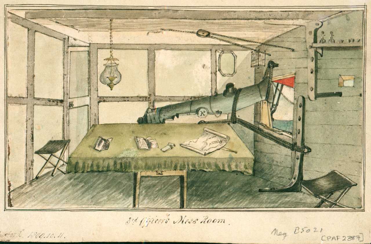
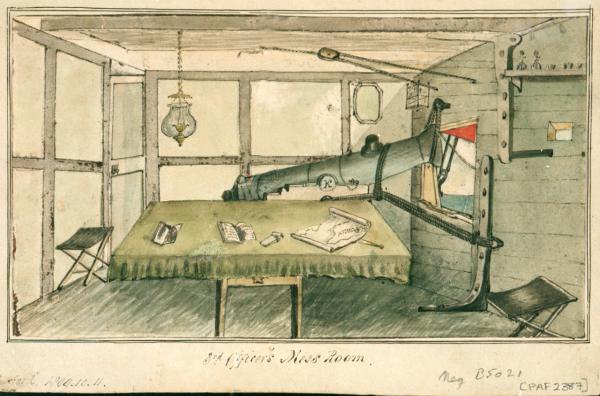
Here is something I found in the net I forget where. Some things puzzle me. First the title - "3rd officer's messroom", I never heard any space of a warship refered to by that name, at least in the period of the drawing 1804, or 08. Then we have a light in the bulwark that I also had never seen. As for the rest it's pretty normal the partition can be canvas over a wooden frame, the gun is in the normal position with normal rigging. Another thing to note is the small cupboard near the deckhead and the folding stools. I hope that someone can enlighten me about this All the best Zeh

-
Seeking information on determining load waterline
rybakov replied to trippwj's topic in Nautical/Naval History
I went throug Nautical Sschool at a time when calculators were not programmable and computers were room sized affairs. Sometimes in Naval Architecture we were asked to determine the displacement of a ship, at a given immersion, from the lines plan. We would start by determining the areas of the sections, then plot the obtained results along the x axis of a graph, and then calculate the area of the graph and that would be the immersed volume, wich multiplied by water density would give us the buoyancy. To undertake all those calculation we used Simpson's Rule, so named ater an English mathematician Thomas Simpson (1710-1761)- So I think that from approximately 1750 on the shipwrights would be quite able to figure out immersions and displacements. Anyway, that's just my feeling. All the best Zeh -
Usually the anchor chain was divided in eight 15 fathom lenghts conected by patent links or shackles. Normally eight such lenghts. To keep track of how much chain was out a number of links on both sides of the shackle were painted white. Also a lenght of wire was twisted around the stay of the corresponding link, i.e. the third shackle would have three white links on either side of the shackle and a twist of wire on the third link on either side. As for red connecting links I don't really recall seeing it Sometimes a dozen or so links nearer to the anchor were also painted white to make it easier to see when nearing the surface an start reducing winch speed. I wasn't sailing in the 30s but I sailed on some trawlers not much younger and I'm pretty sure the way they were run by the bosuns wasn't that much different.
-
I think Jud has a point regarding the tail tackle and recoil. The side tackles were needed to run the gun out, after loading, to be fired. The recoil would bring the gun back to the loading position. A handspike in front of the wheels would be enough to keep the gun steady while loading. What if the tail tackle was only rigged to bring inside an unfired gun? just a thought Zeh
-
Hatch covers.
rybakov replied to mikeaidanh's topic in Discussion for a Ship's Deck Furniture, Guns, boats and other Fittings
I believe the second hypoyhesis is better as if you have a three point attachment you can keep the boat steadier against rolling and pitching. I came across a drawing (painting), I can't recall where that illustrates this perfectly. Zeh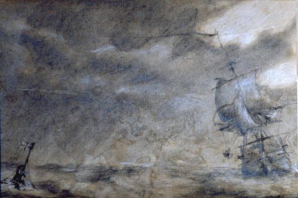
-
Well, I still don't know what they are, but the frame they are in looks similar to present day manoverboard frames. I was, and still am, intrigued, so I searched. In a photo of HMS Captain (1869) in the same position there's something similar, just a dumb bell, no frame. Most photos of Royal Navy battleships show the fitting till1930. The earliest notice of the T shaped fog buoy is from 1912, so I don't think it is a fog buoy. German ships of WWI vintage have a normal round buoy in the same position, so I would think it is some kind of manoverboard. Does anyone know if the Royal Navy used that sort of cross shaped lifebuoy? Zeh
-
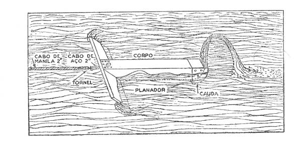
I don't have a clue of what it might be, but a fog buoy should look like this picture, a T shaped thing with a sort of scoop at the end to shhot a plume of water in the air. sorry I can't be more helpful Zeh
-
Hi Jan I reckon I should have remembered that Zeh
-
Hi Daniel Two possible explanations: Powder burning produces gases and heat. It's that heat that makes the gases expand and increases pressure within the barrel eventually expeling the ball. the metal of the barrel absorbs some of that heat. As it gets warmer and warmer less and less heat it absorbs leaving more to expand the gases leading to increased pressure higher muzzle velocity and higher recoil. That's one Another would be that as the gun heats the outside diameter increases and the inner diameter decreases as the muzzle wall expands and you have a tighter fit with less pressure loss. But sincerely....... I really don't know All the best Zeh
-
Hello Dafi According to John Masefield's "Sea life in Nelsons time" the breech ropes were doubled for a general fleet engagement, as the recoil would get more violent as the guns heated being continuouly fired. I wonder what you'll find next to amaze us
-
A question on working mizzen lateen sails
rybakov replied to Stevinne's topic in Masting, rigging and sails
From what I know of portuguese caravels sailing the lateen yard was suspended abaft the mast, instead of in front as the square yards are. So to change tack the lower extremity of the yard would come aft, pass aft of the mast and swung to the other side, to avoid chaffing on the mast and keep the sail shape. And I reckon the manoeuver stayed the same until it ceased to be used, it was not an easy manoeuver and so first the portion of the sail forward of de mast was disposed of, keeping the loose footed sail aft and eventually adopting the gaff and boom. Zeh -
Another picture that may help to find out how things were done. It's a picture of the 3rd officer's messroom. Things I've noticed: whitewashed bulwark, red gunport lid and something I had never seen: a small square vent, probably to ventilate when the gunport is closed. hope it helps Zeh
-
I wouldn't doubt the use of lignum vitae, it is an extremely hard wood. In the late seventies I had a piece of it in my hands and I couldn't find a tool able to score it. As for friction I can tell you it was part of a propshaft bearing on a 10 000Hp bulk carrier, operating at 122RPM, so you can figure out the resistance to wear. In that capacity it was water cooled, but on the other hand it would get more friction in one minute than a block in one hour, so I believe there would have been no problem All the best Zeh
-
Hatch covers.
rybakov replied to mikeaidanh's topic in Discussion for a Ship's Deck Furniture, Guns, boats and other Fittings
As the hatches are in the midship plane I would assume that some sort of stay tackle would be used as in this plate fron Steel's The art of Rigging Hope it helps Zeh