HOLIDAY DONATION DRIVE - SUPPORT MSW - DO YOUR PART TO KEEP THIS GREAT FORUM GOING! (Only 20 donations so far - C'mon guys!)
×

marktime
-
Posts
193 -
Joined
-
Last visited
Content Type
Profiles
Forums
Gallery
Events
Everything posted by marktime
-
Bowsprit with cleats.

-
I think you'll have to do better with your sketch before we can give you an full answer: The bowlines (red) are taken forward to sheaves secured by a tackle on forward end of the bowsprit. The bowlines return to be secured to cleats mounted either side at the base of the bowsprit. I'm not clear as to what you represent with green and yellow lines.
-
Good job there jastrząb. The parrels look authentic Following your build with interest..
-
Is one per mast sufficient? Nice authentic looking sheave block, a double will look even better I'm sure:
-
The standing rigging is a mix of the Fernandez-Duro and Guillén replicas with an eye to creating a satisfying line.The additional rigging that is taken down to the windless is a hoist having seen this feature on other vessels and appreciating the need for a hoist to launch the boats and for loading into the main hatch.
-
Jean-Pierre, pleasure to see you here. Could the foremast be raked forward to facilitate dropping the foresail yard seeing that the foresail could only be furled with the yard brought down to the deck? Bug, a quick look at Xavier Pastor p. 89 has brought me up to speed on the halliard. Ii is what I have called "falls".
- 274 replies
-
- 1
-

-
- Santa Maria
- Artesania Latina
- (and 2 more)
-
Whoa! there my friend- Look at p.112 of your Vanguard. You'll see references to belaying pins, cleats and kevels. The Knight head was a a sturdy fixed block taken down to the keel and a tackle comprised of several parallel sheaves mounted within a single block that was used to raise and lower the main yard. Smith points out that foot ropes were not in use so that the yard was lowered to furl the mainsail. Now to lift a rigged yard took a lot of effort so the main yard hoist comprised two ropes (falls) hauled by two teams at the same time: when the yard was level the order "marry the falls" brought the two ropes together and the crew hauled the yard as one team. Been there, done it with ships boats. Mechanical advantage gained with ropes and pulleys implies the larger the gain, the longer the rope. So there would have been a lot of rope around the knight head when the yard was hoisted and tied into place and I surmise that the likely place that would serve as storage was either lashed to the knight head itself or the rigging above it. Not sure what you are referring to with the "Halliard"
-
Happy Sleuthing! . :D
-
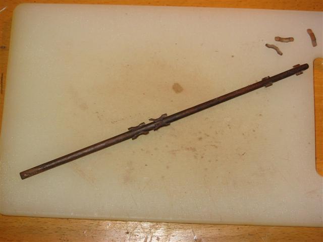
Absolutely agree with you on the pumps. Well, that's because of this....... "Fifteenth and sixteenth century ship's pumps consisted of three main components: a pump shaft, a piston rod and valves......early suction pumps worked on the simple mechanical principle of drawing water up through a tube...... with a one way valve. The pump shaft was fashioned from a a straight tree trunk ...or fashioning a tube of individual planks, like the staves of a barrel.....The base of the pump shaft in the bottom of the bilge was fitted with a foot valve made up of short baulk of bored wood fitted with a leather flapper valve on top........Water usually exited the pump tube through a hole in its side near the top above deck level. On the fourth voyage, Columbus was forced to stand for Jamaica, "especially since the ships were so eaten by shipworms, that day and night we never stopped pumping water with the three pumps. If one broke down, kettles were substituted for the job while it was being fixed. Despite these efforts, the caravels could not be kept afloat and at God's mercy, we beached in Jamaica." Extracts from "Vanguard of Empire - Ships of Exploration in the Age of Columbus" Roger C. Smith. Oxford University Press. A fantastic resource for information on the architecture and building of ships of this period. Bug, your detail looks very authentic, makes me want to go back and redo mine!
- 274 replies
-
- 3
-
-
- Santa Maria
- Artesania Latina
- (and 2 more)
-
Liked the bombards (which you are calling cannon, tut! tut!). And thanks for the acknowledgement. There are three other Santa Maria builds on this forum and you are doing a great job in inspiring them to go that extra mile.
- 274 replies
-
- 1
-
-
- Santa Maria
- Artesania Latina
- (and 2 more)
-
The twist probably comes from your method of threading the dead-eyes. Try another threading sequence so that when you pull on the top dead eye the threads stay flat. Otherwise, nice build.
-
That is an excellent introductory log and many would do well to learn how to present their work in such an interesting fashion. Good job on the railings. Add my pleasure to see you here again with the others.
- 274 replies
-
- 1
-
-
- Santa Maria
- Artesania Latina
- (and 2 more)
-
Coming on nicely.
-
Spray them with a starch and then use a blow-drier to shape them.
-
Muy bonita, como siempre. From your good friend in Tenerife.
-
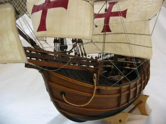
62 are the spritsail sheets, ropes that allow the the spritsail to be trimmed, i.e. to keep the sail filled with wind.. One end will be fixed to a cleat mounted on the inboard face of the foc's'cle bulwark and the other belayed on the belaying pin No. 62. These sheets are normally left slack on the model as there is no counter force to keep them taut. Edit: My interpretation of the Santa Maria based on the Martinez-Hidalgo replica has only a single sheet for each foot of the spritsail so in that case, you have a single rope to belay on pin 62.
-
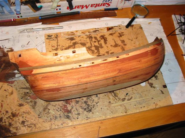
Kimberley. Just to reassure you that your placing of the bowsprit was correct: its foot passes the the foot of the foremast below deck and as the foremast is on the centreline the bowsprit is angled so it to comes up through the foc's'le off-centre. Tucks, the architectural name given to the stern configuration. Most of the wooden model kits for pre-XVI th century vessels are supplied as square tucked because it's easier to model, so the stern is flat. Your model has a nice round bottom.
-
Aah! Good to see a round tuck on the Santa Maria. Square tuck arrived in the XVIth century.
-
We are having even more fun watching your build. I'm learning a lot about plastic models just by following your progress. 'Aint this forum wonderful?
- 94 replies
-
- 2
-
-
- santa maria
- revell
- (and 1 more)
-
Yes I noted the electrics. Will look stunning when it's finished.
- 79 replies
-
- 1
-
-
- santa maria
- amati
- (and 2 more)
-
I think you are being too modest! Great hatch cover hinges. Are you going to add a way to lift the hatch cover?
-
You are demonstrating a very high standard for a novice modeller so I imagine you are a craftsman in some other trade. An outstanding build and a well photographed progression of your work.
-
i can't recall where they meet the maindeck but yes, it follows the line of the maindeck and it's a pretty tight turn so you´ll need to peg it along it's whole length. Hope we are not barging in on Sephirem's build log, if so, apologies.
-
Just to clarify, here a couple of pics. I bashed my SM so the bulwarks are different but their positioning is identical to the kit instructions.
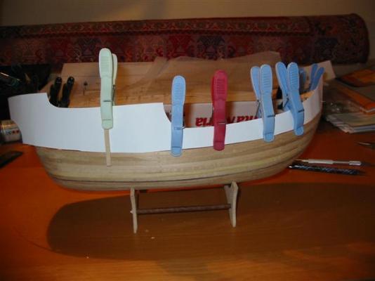

-
Changing the colour of the dead-eyes rigging is a great improvement.