

tarbrush
-
Posts
437 -
Joined
-
Last visited
Reputation Activity
-

 tarbrush reacted to Louie da fly in The San Marco mosaic ship c. 1150 by Louie da fly - 1:75
I've been experimenting with weathering, and I'd like the team's opinion. I don't really want the ship to look completely neglected, but I'd like to show that she's been in use for a good while. Here are two tests I made to weather the decks - the first was using a thin (water-base) wash of acrylic - not too good because the water made the fibres of the wood rise up. The second I used (black) enamel thinned out with mineral turpentine. What I'd like to ask the team is - is this too much? Does she look like a tramp, rather than a normal ship that's been reasonably kept up, but has been exposed to the weather over a good period of time?
The other problem, by the way, is that there are bald spots where the paint has been over the top of white glue. I'm hoping I don't encounter this when it comes to the real thing.
On to the rest of my recent progress. Making and installing the pumps:
I thought long and hard about how to fix the lower ends of the shrouds. I decided (as this is the Mediterranean) to use pairs of blocks, not hearts or deadeyes. But there's simply no evidence at all of how they were fixed to the hull in 1150. Nix, nada, nuthin'.
I've made a series of beams attached to, and joining, the fronts of pairs of frames. In each one is an eyebolt to hold the lower end of the strop around the lower block, plus a vertical peg to tie off the downhaul. This is a possible configuration, but is almost certainly not what was actually used. But in the absence of available evidence, hey, what can you do? Certainly, I don't think anybody can prove I'm wrong.
Eyebolts from garden tie-wire:
This had a high failure rate - I used a pair of fine long-nosed pliers to do the bending, and quite often the shape just turned out wrong. I've kept the failures in case I can use them for something where the wonky shape doesn't matter.
Beams with eyebolts:
Pegs under way:
Checking diameter:
Cut to length
And dry fitted
Steven
-
tarbrush reacted to Louie da fly in The San Marco mosaic ship c. 1150 by Louie da fly - 1:75
Thanks everybody for the likes and comments.
I'm afraid I'm not very systematic in building. I often make things as the mood takes me rather than follow a logical sequence. Sometimes I end up painting myself into a corner, but so far I've mostly managed to avoid that on this build (touch wood).
I've puzzled for some time over how to support the spears and other pole-arms sticking out at the stern shown in several of the mosaics.
I came up with several ideas but none really seemed likely or workable, until I thought of two metal hooky things, (made of bent wire) attached to the uprights of the side railings, to support each shaft.
First I tried adding them to the existing uprights. But there was too little space to make the holes to take the hooks and the uprights were too narrow - the holes were almost the width of the uprights.
So I removed the existing uprights and made new ones rather wider but still looking like they belonged, made the holes and inserted the hooks before putting the new uprights in place.
Here are the pole-arms. Mostly simple spears but one was more like a harpoon and another had a head in the shape of a shepherd's crook - which I believe was intended to cut the rigging of an enemy ship.
Took a fair bit of work - they're pretty small - but finally got them done. Painted the heads silver, and the hooks on the railings black to resemble forged iron.
And here they are dry fitted in place. You can see the pole-arms sticking out the back railing.
I've also been working on the lateen yards, for the fore, "middle" and mizzen masts. Each yard is made of two spars lashed together; the upper one longer and with a "hollow" cut into it to take the lower one. (Thanks to Woodrat for the information on how these were configured).
Here they are glued together:
And with the lashings in place.
Steven
-
tarbrush reacted to KeithAug in Cangarda 1901 by KeithAug - Scale 1:24 - Steam Yacht
Rick - I have been meaning to ask - can you remember what colour she is? She sometimes looks very green and sometimes very blue.
-
tarbrush reacted to KeithAug in Cangarda 1901 by KeithAug - Scale 1:24 - Steam Yacht
I am taking my time preparing stuff before I commit to the glue.
I sorted out the small frames at the bow and stern.
I spent a happy day stripping the cutting templates from the frames. I didn't find any of the usual solvents worked particularly well on pritt stick adhesive but peeling / sanding worked ok.
The cut line for the deck made the frames very flexible and I wanted them to be a little stiffer for the future hull sanding process. I therefore temporarily glued small strips of wood across the deck cut line to increase the stiffness.
I also sorted out the correct vertical position of the keel. The keel slots were cut deeper than needed so I cut the keel strip and then assembled it into a few of the frames before setting it to the correct heights fore and aft. With friction holding the keel in place I glued tabs to the frames to fix the keel position.
The line of the keel is broken at frame 61 and the next job is to sort out the position of the aft section of the keel.
Not very exciting but progress is progress.
-
 tarbrush reacted to Richard Dunn in Cutty Sark by Richard Dunn - 1/40 scale - scratch built semi-kit prototype
Frame complete
The remaining work is to glue the Tween decks into place which are already inside the hull, and can be moved around to expose beams for gluing, which is a relief.
Just the decks to glue, sheer plates to fix and bilge stringer to attach, the stem and sternpost will now be braced plumb and a few midship frames braced level before the decks go on.
Note the frames are pre bevelled by gluing on patterns and filing, the ends of the fore frames can be seen where it runs out due to being too thin, these will be done when the hull getsa quick sand prior to planking.
The Tween decks get held down with 38mm sticks as the Tween deck is parallel to the maindeck
The counter perimeter is here seen clearly, and note how it is higher than the deck, this is to align it to the white moulding around the hull as it is higher than the deck, one of the things models normally cheat on for ease of build, even Longridge made this shortcut but it alters the design and look of the ship so this is as close to the ships structure as possible.
The mainstay lugs, these get pinned to the carlings to take the strain of the Main stays.
The Saloon being assemble inside the counter frames to keep its shape.
-
tarbrush reacted to davec in East Coast Oyster Sharpie 1880-1900 by davec - FINISHED - 1/16 scale
No log entries in two years, but I have been slowly plugging away a few minutes a week. I had a pretty steep learning curve silver soldering the brass fittings for the masts and figuring out how to make the mast hoops. Rope was made with Chuck Passaro’s rope rocket. Rigging relies heavily on John Leather's The Gaff Rig Handbook. When the book didn't have the necessary detail, I defaulted to the advice from the Mystic Seaport staff restoring their Sharpie - "These boats were built in people's backyards with what they could make or get from their local hardware store." I did not want to make sails and there is no rigging exerting downward pressure on the gaff, so rather than having limp rigging, I lowered the gaff as if a mainsail was about to be attached. Both kids were with their partner’s families this Christmas, so I got to spend some concentrated workshop time and finished this morning.
Next project is a case – I got some good tools for Christmas (router table, acrylic cutting table saw blade) so I should be able to build one. I made some acrylic shelves for my display case, so I’ve got the cutting and edge polishing down, and just need to sort out the gluing.
Happy New Year Everyone!
-
tarbrush reacted to ccoyle in Sopwith Pup by ccoyle - FINISHED - Kartonowa Kolekcja - 1/33 - CARD
The Big Reveal!
After pretty much an entire day spent modeling, the Pup is complete! The most labor-intensive task was adding the rigging -- if I counted correctly, the rigging amounted to 38 separate lines. Whew!! Sqn Cdr Dunning's Pup had some 'handles' of some sort attached to the rear fuselage -- I suspect that these were used by the crew of HMS Furious to maneuver the Pup about the flight deck; in photos, the handles appear to be made of rope and look like they may have been wrapped in leather or perhaps tarred. Mine are made of wire and painted black. Also in the photos, I just now noticed that similar rope handles were attached to the underside of the lower wing -- these were not shown on the kit plans, so I will not add them. Getting the Lewis gun onto its mount was a little tricky, and of course the mount had to break during the photo session (🤬🤬🤬), but it's fixed now.
As was pointed out to me earlier, the starboard lower wing is canted aft a degree or two -- fortunately, the finished Pup now sits on the Shelf of Fame with her more photogenic port side facing the viewer. Enjoy the pics!
-
tarbrush reacted to Louie da fly in The San Marco mosaic ship c. 1150 by Louie da fly - 1:75
Thanks, Pat. I'm pretty chuffed with how they came out, but . . . see below.
Dick, I haven't seen hawse holes in any representations earlier than the 14th century. They may just not have been invented yet. But certainly the bitt in that opening would probably be doing the same job, even if not quite so efficiently. I agree about rabbeting the joints. Much better. And though the joint was probably nailed, my idea was to fix each join with a treenail. Regarding the possibility of an anti-splash cover, well, could be. But I'll go with the way it's presented in the mosaic. I'm doing enough speculation as it is without adding more.
Now for the bad news - after a period of existential angst, soul-searching and questioning the meaning of existence I came to the conclusion that those braces just didn't look right. I can't see what purpose those exaggeratedly complex curves would serve, why any shipwright in his right mind would go to all the trouble of making them and why any skipper in his right mind would ask for them. Yes, they are a possible interpretation of the mosaic, but not a likely one. I think Occam's razor - the idea that the simplest solution to a problem is probably the correct one - applies here.
After some discussions with and suggestions from Woodrat (thanks, mate!) I've re-considered the braces and made them simpler. Still a 3-dimensional curve, but more logical. But first I revisited the mosaic and decided the stempost was much more curved, and wider, than the original picture shows.
So I decided to trim it down to be closer to the one in the picture. Note the pencil line in the photo above. Even that wasn't quite right, so I didn't follow it exactly.
Then I put in the rabbets in the gunwales to take the braces.
And corresponding rabbets in the top of the stempost to take the other end of the braces. (I later changed the angle of the rabbets so everything fitted as smoothly as possible - a bit of trial and error involved in getting it quite right.)
Here are the new braces. Much simpler, and they carry the curve of the gunwale up smoothly to the stempost.
A tiny bit of tidying to do, but I'm much happier with this version.
Steven
-
tarbrush reacted to Richard Dunn in Cutty Sark by Richard Dunn - 1/40 scale - scratch built semi-kit prototype
I can finally show a dry fitted frame almost complete.
Of course this is all just leaning together right now and parts are missing but its the bulk.
The Foredeck housed into the heads, the forward end gets housed into slots in the knightheads, leaving the underside clear for styrene framing as per the actual ship. Note this is a standin Fore deck the actual is laminated over a form from 2 layers of .4mm ply to make sure the camber and fore and aft sheer is in the deck and needs no force to shape.
Details of the Poop construction.
The slots for the counter cant frames.
The variance in steps in the counter parts are deliberate and its designed to forma definite seat for the counter bulwark ply sheet so it sits in a rebate.
A nice shot of the frames and Rabbet
.
The deck joints came up well, they hold themselves together dry..
-
tarbrush reacted to gak1965 in USS Kearsarge by gak1965 - BlueJacket Shipcrafters - 1:96
And kick-off.
This model is built rather differently than the POB models that Model Shipways sells, in the sense that the 21 bulkheads are in 42 (rather than 21) pieces, one port and one starboard piece, each of which has a tab that fits into either the top or bottom half of a slot on the main keel. It is also different in the sense that it appears that I am going to add the keel after the hull is planked (in prior kits, I'd cut a rabbet into the bottom of the hull, and then added the keel and bulkheads, before planking.
Here is everything dry fitted on the port side:
and all of the bulkheads cut out and aligned, port and starboard, fore and aft (the sections with the holes are for a reveal). There are also 21 2 x 1/2 x 1/16 strips of wood that I cut out that are going to 'lock' the frames in place.
Observations so far. The laser cutting is generally pretty good. I had no trouble with the main false keel, and 3.5 of the four sheets of frames. At one end of one sheet, the cutting hadn't gone as far as it should, and even though I was careful cutting the parts out and used a fresh blade, I wound up with broken tips on two of the frames. They broke by having the two outer layers of ply break off, so I just repaired them by cutting out a section of ply of about the right shape, gluing them to the stub of ply and then trimming it down. It added about 20 minutes of work, but no big deal.
One other thing I've noticed is that the tabs on at least some of the bulkheads are a little too long, and they protrude in a way that would prevent the opposite side from attaching securely to the false keel. Again, no big deal, I'll sand them down a little bit before I start attaching them.
Regards,
George
-
tarbrush reacted to gak1965 in USS Kearsarge by gak1965 - BlueJacket Shipcrafters - 1:96
I'm currently building out the plans and parts for a scratch POB version of RRS Discovery. That is probably at least a month away from making any kind of sawdust, and I wanted to have another project where something other than electrons and paper was created, so I've decided to do the Bluejacket USS Kearsarge. This is my first Bluejacket kit, although I've used many of their parts/supplies in the past.
There are other logs, and I won't reiterate what you can find on the Bluejacket website. Suffice it to say that she is a Mohican class steam sloop-of-war, built in 1861 by the Portsmouth Navy Yard in Kittery, ME, and commissioned in January 1862. <aside>If you look up Mohican class on Wikipedia or Google you will initially find the article on the Mohican herself, the Kearsarge and the Oneida (which sank with the loss of 125 in Japan. So far, my far from significant research has turned up 6 of them, two from 1859 (Mohican and Iroquois) and 4 from 1861 (Kearsarge, Oneida, Tuscarora, and Wachusett)</aside> Kearsarge is best known for sinking the Confederate commerce raider CSS Alabama. This particular battle caught the world's (and certainly the art world's) attention. I have read that only the battle between the Monitor and the Merrimack/Viriginia yielded more naval art in this period than the Kearsarge/Alabama fight. I will leave it to the psychologists as to why (larger than life personalities? the appearance of a chivalrous duel? Good artists nearby?), but there is a lot of such art out there. The default one is this one by
Manet (image is public domain). It has been pointed out by people with more artistic skill than I that Manet changes the focus to the French ship coming to rescue survivors and that Kearsarge is barely visible.
Manet:
This is another one by Antonio Jacobsen and shows the Kearsarge nicely, with what appears to be a pretty rational rig.
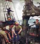
Just one more photo, this one of the ship's officers:
I love this photo for what it says about life on board a navy vessel. This was apparently taken after the victory against the Alabama. At this point, this is probably the most famous ship in the Union Navy, Captain Winslow (3rd from left in the front row) is a national hero but you'll see that he is still wearing the old insignia for a Captain (3 3/4-inch stripes), while his junior officers (who presumably are newer at this than he is) are wearing the up to date version using more, narrower stripes (in the 1864 version of the regs, Captain Winslow would wear six stripes in two groups of 3, of the same width as the two LCDRs on his right). Bottom line was that he was on duty and had better things to do than replace his dress coat - not like anyone on the ship was going to be unaware of who he is!
So, let's get the initial requirement out of the way. Here is the mandatory photo of the kit on my clean work table (not for long!).
As to why this kit, well, it links a couple of areas of my interest. First, it is a Civil War era kit, and I've been fascinated by the history of that period for decades. Second, Kearsarge is, in some ways like Discovery, a transitional ship, powered both by steam and sails, and those transitional vessels have started to attract my interest of late.
This project is going to be rather different in many ways from the kits of built recently (three Model Shipways kits, the Pride of Baltimore II, Niagara, and Flying Fish). This is much more 'mixed media' than those in the sense that there are wood parts, Britannia fittings, wood and metal strip, cast resin, styrene, and photo etched brass (a LOT of photo etched brass) so it will no doubt require developing some new skills. I am going to bring some techniques from those other ships though. For example, rather than paint the hull copper or using the individual copper plates, I am going to copper the bottom more or less as I did the Flying Fish using copper tape, and hopefully I'll be able to learn from my myriad mistakes on all the prior models to make this one go smoother.
Regards,
George
-
tarbrush reacted to Louie da fly in The San Marco mosaic ship c. 1150 by Louie da fly - 1:75
And painted black to represent waterproofing with pitch. It's all a bit monotone now - I'm thinking of perhaps doing a bit of weathering down the track to add a bit of interest. I haven't weathered a model before, so I'll have to do some research before I start.
Steven
-
tarbrush reacted to woodrat in The San Marco mosaic ship c. 1150 by Louie da fly - 1:75
I agree with Baker. That black could be toned down with a light buffing, Here are some bangladeshi boats to show effects of wear on pitch,
Dick
-
tarbrush reacted to Louie da fly in The San Marco mosaic ship c. 1150 by Louie da fly - 1:75
Well, I dry fitted the stuff that's already made but not ready to be fitted, just to get an idea of how it's going to look..
And I tried a bit of mild weathering by sanding lightly with fine grade sandpaper in places where I think there'd be a bit of wear. Didn't turn out too badly at all. Encourages me to go a little further (without pushing it too hard - I don't want to mess it up).
Mark, that's two coats of standard cheapo acrylic from a school-style set for doing pictures with.
Steven
-
 tarbrush got a reaction from Helge Hafstad in Gjøa by Stavrogin - Constructo - Scale 1:64 - first wooden build
Hi Simon,
you are doing an excellent job on your model, Gjoa is an very good choice as your first model, it has just the right amount of complexity for a first build.
Have you checked out all the photos there are of Gjoa on the net? am attaching a couple that I like. I look forward to following your progress.
-
tarbrush reacted to Louie da fly in The San Marco mosaic ship c. 1150 by Louie da fly - 1:75
So here's the "bow brace" (see my previous post). Very complex 3-dimensional curve, bent using soaking in water plus my trusty soldering iron. A bit of charring, but as it's going to be painted black it really doesn't matter.
I'm actually very happy with this - I've come a long way in heat bending since my first attempts on the dromon model about 7 years ago. The two sides are virtually identical mirror images of each other, and look a lot like the original mosaic.
I have no idea if this is really what that thing looked like, but it seems to work for me.
And here's the windlass with holes cut and ready to install.
Steven
-
tarbrush reacted to Rick310 in Cangarda 1901 by KeithAug - Scale 1:24 - Steam Yacht
Those were photos of the engine room, pretty cramped. The rest are topside and in the cabins.
-
 tarbrush reacted to Chuck in I am sad and devastated to announce the passing of Jim Byrnes, my dear friend and owner of Model Machines
I can not explain how devastated I am to be announcing this. My dear and close friend Jim Byrnes has passed away way too soon. Many have you know and have met Jim. He was a fantastic guy and true original. Many of you own his tools which are second to none in the hobby. I have been speaking with his wife Donna who many of you also know. Jim was diagnosed with ALS in February. ALS is a nasty disease and there is no cure. Jim had a particularly aggressive type of ALS and he passed away last month in October. He was just 64 years old.
This news will be devastating to many...but Donna has asked if everyone would have patience and give here and their family time to grieve. As you might expect, the business will continue to be shut down, but will reopen at some time in the near future. Donna will continue supporting the hobby and their customers when the time is right. But please have patience and allow the family to grieve at this sad time. Donna will let me know when the shop will reopen. I will make an announcement at that time.
I am so devastated by this...I just spoke to him not too long ago and it breaks my heart. His obituary is below.
Jim is survived by his wife, Donna; son, James William (Krystal) and grandchildren Julian and Sloane; brother, Peter (Cindy) Byrnes and sisters, Mary (James) Hayman, Catherine Byrnes, Veronica Byrnes and Elaine Byrnes (Robert Campbell); brother-in-law, Eddie (Marcia) Grissom; brother-in-law, Frank Marzovilla, and many cherished nieces and nephews. Not to be forgotten is his beloved English Springer Spaniel, Becky, who is waiting every day for him to come home to her!
He was preceded in death by his parents, James and Lorraine Byrnes; brother, Robert Byrnes; nephew, Michael Byrnes; brother-in-law, Pete Stuffer; and mother-in-law, Opal Grissom.
Along with restoring vintage cars, from a very young age Jim had a true passion for model ship-building. For many years he had done extensive research on the U.S.S. Constitution and was in the final phase of completing his scratch build of the Constitution as it was originally launched in 1797. Following a career of working with Defense contract companies, Jim worked many years with and became a partner with Conceptual Engineering in Sanford FL. In 2002 Jim and Donna formed Model Machines LLC. Jim designed and developed small modeler’s machines that are now purchased worldwide and used in many high school and college machine shops and in museums for their restorations. There have been numerous reviews and articles written about Jim which were published in various modelers’ magazines. Modelers using Jim’s machines range from ship, railroad, doll houses, doll house furniture, pen turners, segmented bowls and architects. In recent years guitar, harp and violin makers were added to this list. Jim was a remarkable craftsman and had many more machines in development stage for modelers. He was always ready to help and mentor others, many of whom soon became his very close friends.
Jim was also a member of the Nautical Research Guild and attended conferences throughout the U.S. for 20 years, developing many close friendships within this organization.
Jim was a humble, quiet man who was deeply loved and will be missed by so many. Our hearts, as a family, are broken. Thru this profound loss, if we can ask one thing from this place of despair, it would be to embrace your loved ones every chance you get.
-
tarbrush reacted to RossR in Cutty Sark by Richard Dunn - 1/40 scale - scratch built semi-kit prototype
I hope you continue to post. I have had similar thoughts of discontinuing posting after the kit I am building was criticized in a non-constructive manor when I posted about successfully bending African walnut on a topic about bending African walnut. The vast majority of the users on the forum are 100% positive. There are a small minority that will occasionally make a comment that I feel is outside the guidelines of the forum. I know many would love to see build logs of your Cutty Sark project and I hope we have that opportunity.
-
 tarbrush got a reaction from FrankWouts in HM Cutter Cheerful 1806 by Chuck - FINISHED - 1:48 scale - kit prototype
I've been looking forward to this build Chuck. Now I know what I will be getting myself for Christmas.
-
tarbrush reacted to Brinkman in One more small cog c. 1410 by Brinkman - scale 1:13
So, I have just finished my build of a small 15th century cog and while I am pleased with the result, there are some things I wish I would have done differently. The only reasonable thing to do is to start over again 😛
Old build:
I guess most people would start with a new ship, but I don't feel like I'm done yet with NZ43 and would like to fix some issues, and I would like your help to find them. Here is my list of changes, and I would very much like to hear your thoughts on them.
Wood
The old model used fir and it it was just as bad as everyone here told me. I will look for pear, but I guess I will not find it and use birch instead.
I bought the old wood in planks, but now I have space to buy a small tablesaw and saw my own wood. But before buying it I will try sawing it by hand and see if it would be feasible as I like the idea of it.
I don't liked how I soaked the planks in hot water, I think I will try a steambox this time.
Scale
One thing I really wanted to do with the old build was to use functioning nails, but the scale proved to be just too small. I think it will be better if I now make it 50% bigger length wise. (I thought 50% bigger than 1:20 would be 1:15, but apperently it is 1:1333... Not as a neat and round number as I had hoped. Calling it scale 7.5% sounds better.)
Frames
I didn't much care in the last build about where the joint between futtock and floor timber was and I built it frame first.
Now I will build it bottom first, ie the bottom will be frame first and the rest shell first. This way the floors will be shaped and attached to the keel plank and the futtocks will be shaped and attached afterwards. I do not know how to do it, but I'm sure I will find a way
Layout
The hold was way too small in the last build. The layout was like this
Red - decks
Green - ceiling
Blue - large beams and masts
Pink - bulkheads
My new proposal is like this instead
The fore deck was way too big and it can be cut down a lot and lots of cargo can be stored there.
The bulkheads are moved to where the decks begin and will be like this with twin stanchions, vertical planking and a door. This design is from the Almere 13 wreck. Perhaps a bulkhead also under the beam aft of the mast to seal off the ceiling area?
And yeah, the bipod mast was a fun build, but I will ditch it for a normal single mast with a normal mast step. And I guess the lifting boom will also have to go.
The old decks were not waterproof, but the new ones will be.
Cleats
The old cleats were thought of in the last minute and just wrong. I think I will integrate them in the knees on the decks.
Sheer height over decks
I have no clue of what this is called, but I'm talking about this measurement
It is so small on my build. But increasing it means smaller decks and less storage space. How much bigger must this be? The Almere 13 wreck seem to have double the height, but that ship is also a bit bigger than mine.
Any thoughts of other things I should fix?
-
tarbrush reacted to Louie da fly in The San Marco mosaic ship c. 1150 by Louie da fly - 1:75
Here's my first attempt to do a calcet based upon the mosaic ships. There was quite a bit of guesswork involved - even guessing that the black things above the tops actually were calcets rather than something else - I'd originally thought they were either the mastheads or flagpoles, but their strange shape, pretty much consistent in 4 out of 5 of the mosaics got me thinking they must be something else, and the only thing that seemed to fit was a calcet.
Why a calcet would be that particular shape, I have no idea. But I can understand that there could be a wide variety of shapes that would still do the job. So rather than get too involved with the mystery of the shape (that can be for later) I just made one that seemed to be the right shape and would do the job. Based on pictures of calcets - both drawings from some centuries later than this model, and the photo of the Ma'agan Mikhael calcet referenced above, I've given it two sheaves. I worked out a possible configuration to make that work, but again, this is pure speculation.
There are two tyes attached to the lateen yard, each of which runs through one of the sheaves in the calcet (at the top of the mast) and down. They come together to form a strop around a block which connects via the halyard to a knight at deck level. There's no direct evidence that this is how it was done, either iconographic or written, but it should work.
So here is the calcet for the mizzen, with a scarph joint to connect it to the mast itself.
Note: The scarph joint doesn't line up perfectly - this is a prototype; I've cut it right up at the top of the mast, above where it's supposed to be, just to see if it works. As it seems to be ok I'll now do the real joint in the correct position - the bottom of the joint should be in line with the base of the "crow's nest". I think I can arrange things to the tyes don't foul the sides of the crows nest, which is an open framework (see pictures in post #155 above).
I've also added more deck beams for the main hull and finished the deck beams for the aftercastle, with openings for the mast partners and for a companionway coming up from the cabin space below.
And then I removed the aftercastle to work on the deck beams and sides.
I added a railing around the aftercastle, which is how I interpret the mosaics.
Next I plan to do all the rest of the deck beams (allowing openings for two hatches - one between the aftercastle and the central mast, and one between that mast and the foremast). And make and install beam clamps for the deck of the cabin below the aftercastle. Unfortunately my cheap soldering iron which I've been using as a plank bender, up and died today, So it looks like I'll have to get another one - unless I can make the vegetable steamer do the job. Worth a try.
Steven
-
tarbrush reacted to Louie da fly in The San Marco mosaic ship c. 1150 by Louie da fly - 1:75
A-a-a-and - the hull is off the jig. I ended up having to pull the jig apart to get the ship out, but worth it. Then I had to do some correction. The pegs are gluing into the correct position some frames that were angled incorrectly (not perpendicular to the keel).
Then onto making stringers to make the structure more rigid, and deck beams. Here's my poor man's plank bender (a cheap soldering iron) to get them the right shape.
And here are the first bits of deck beam - or are they stringers? I've sort of lost track. (one of them is to be cut up to provide pieces of stringer for the bow or stern, which explains the complex curve).
Gluing complete - here she is without the pegs.
Adding stringers at the turn of the bilge. There'll be corresponding wales on the outside of the hull, and there'll be strengthening stringers and wales where the second and third futtocks join, and a wale in line with the clamp.
The mosaics seem to show a reasonable number of wales, as do the near-contemporary picture from the History of Genoa and the carvings on the Leaning Tower of Pisa.
View from the bow.
I'd miscalculated the length of the clamps, so they didn't quite reach the breast hooks. Because they didn't meet the rigidity of the hull was lessened, so I glued bits of wood into the gaps to make each assembly effectively a single strong unit.
Smoothing off the pieces that fill the gaps.
Still some tidying up and smoothing off to do. They won't be visible under the deck, but I'll know if I don't do it right.
And the stringers lined up with the join in the futtocks. They will be curved to follow the line of the join.
Like this . . .
And that's it for today . . .
Steven
-
tarbrush reacted to Zetec in USS Cairo by Zetec - 1/50 scale
This is the next lot of pictures which show the wires for the lights and the start of the planking.
-
tarbrush reacted to Zetec in USS Cairo by Zetec - 1/50 scale
This next lot of pictures show some of the planking finnished and the type of light I used on the inside were you cant see the type used which are LED with a plastic cover put on them.