HOLIDAY DONATION DRIVE - SUPPORT MSW - DO YOUR PART TO KEEP THIS GREAT FORUM GOING! (Only 20 donations so far - C'mon guys!)
×


rvchima
-
Posts
697 -
Joined
-
Last visited
Content Type
Profiles
Forums
Gallery
Events
Everything posted by rvchima
-
 Handrails This morning I took a deep breath and drilled about 300 holes for the handrails. The manual calls for 0.7 mm diameter holes so I removed one stanchion and checked the fit. That was way too big but my smallest drill bit, 0.56 mm diameter, worked well. My deck planking was too close to the edge in many places and I ended up trimming little slivers off.
 -
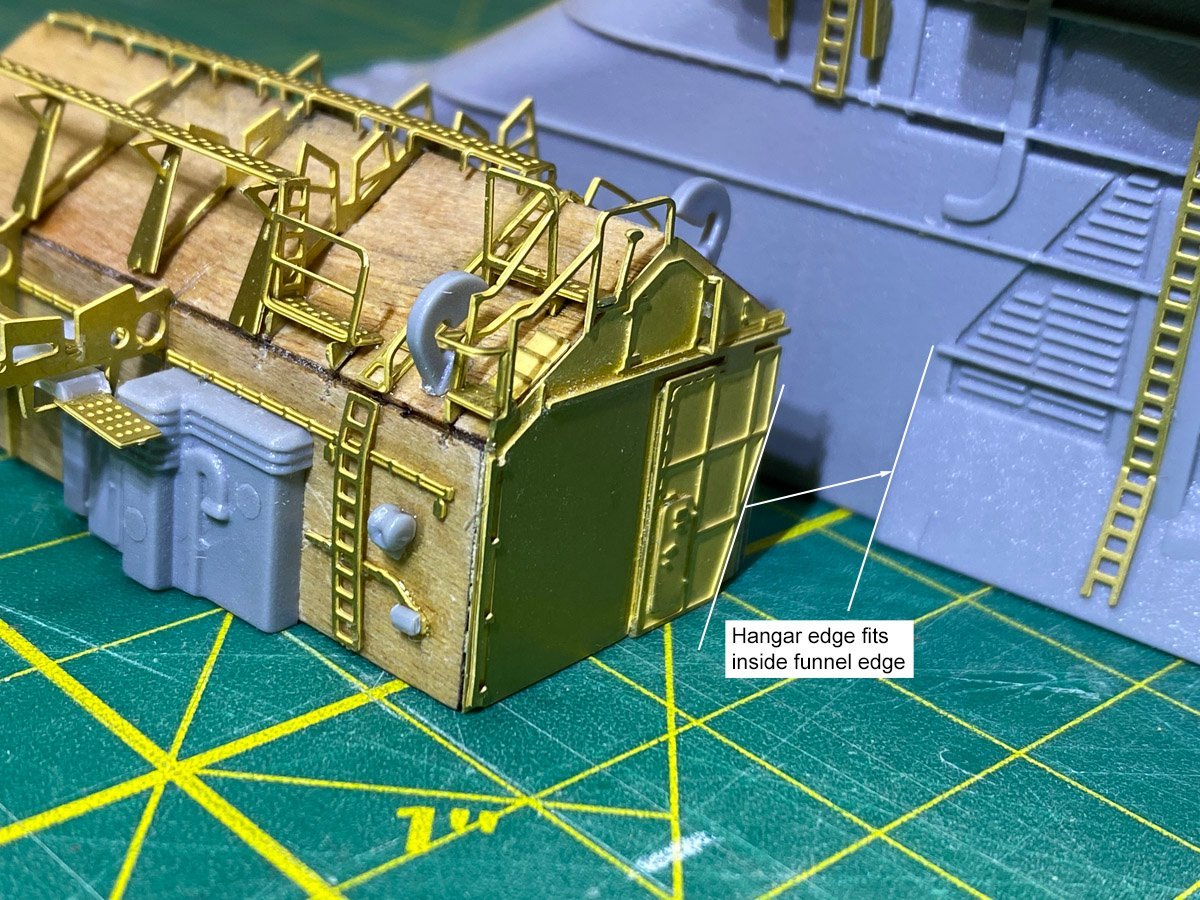
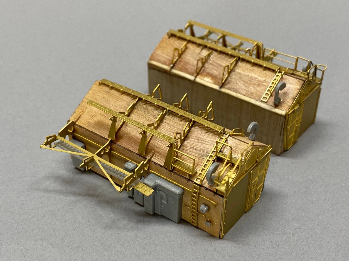
Harry, My hangars are 26.3 mm wide x 58.7 mm long. It took me a while to realize that the triangular cutout in the brass ends of the hangars fits exactly against a triangular step on the funnel. If you're not against that edge the hangars might protrude a bit.
-
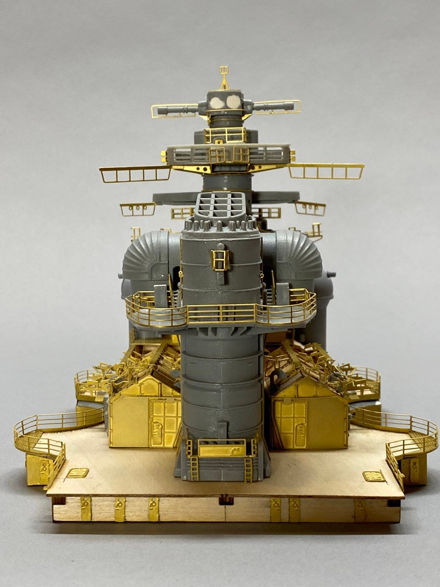
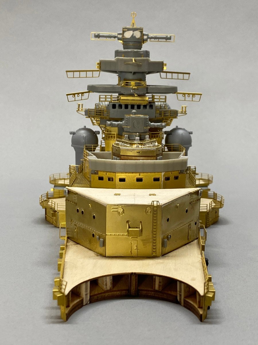
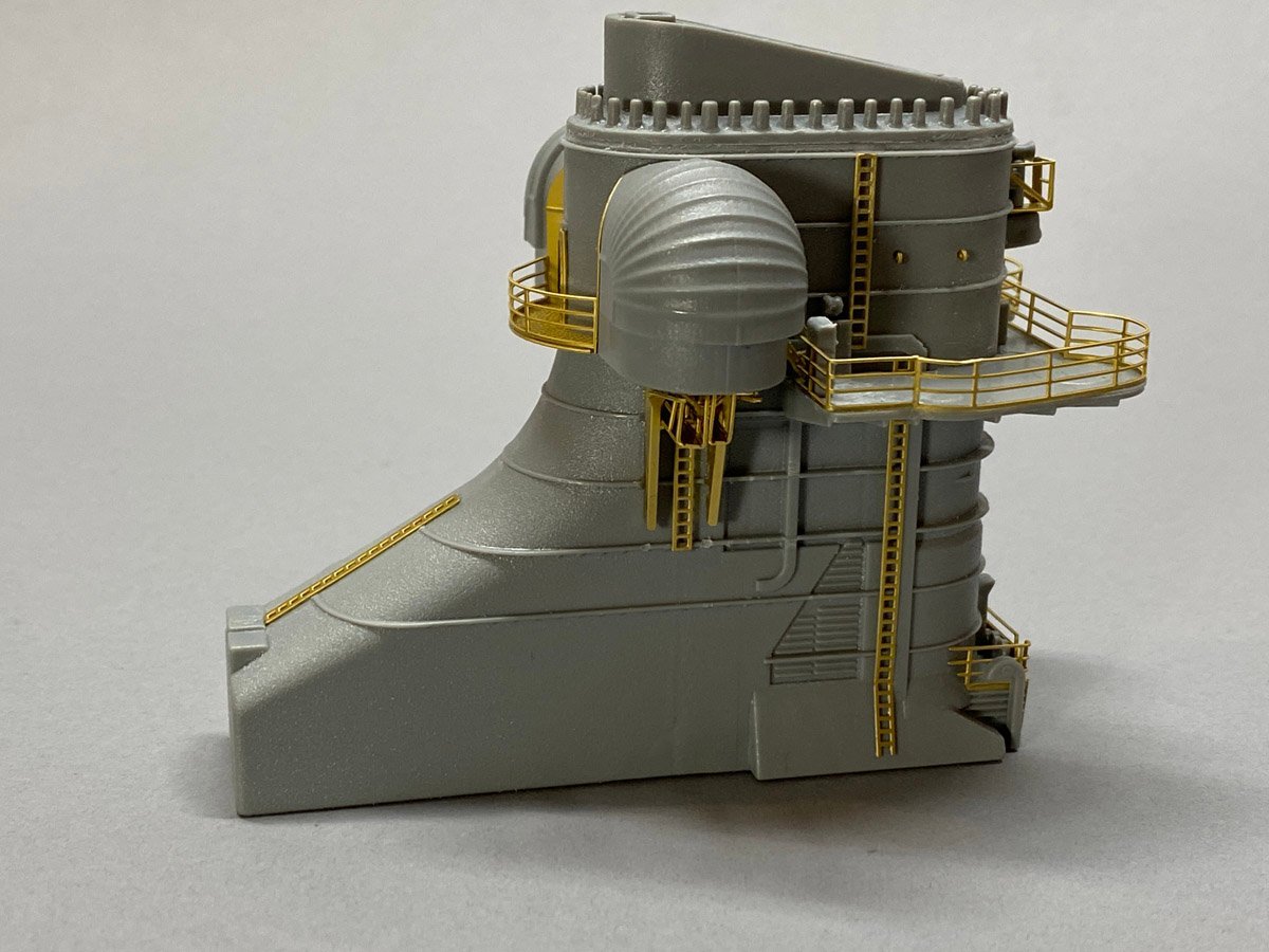
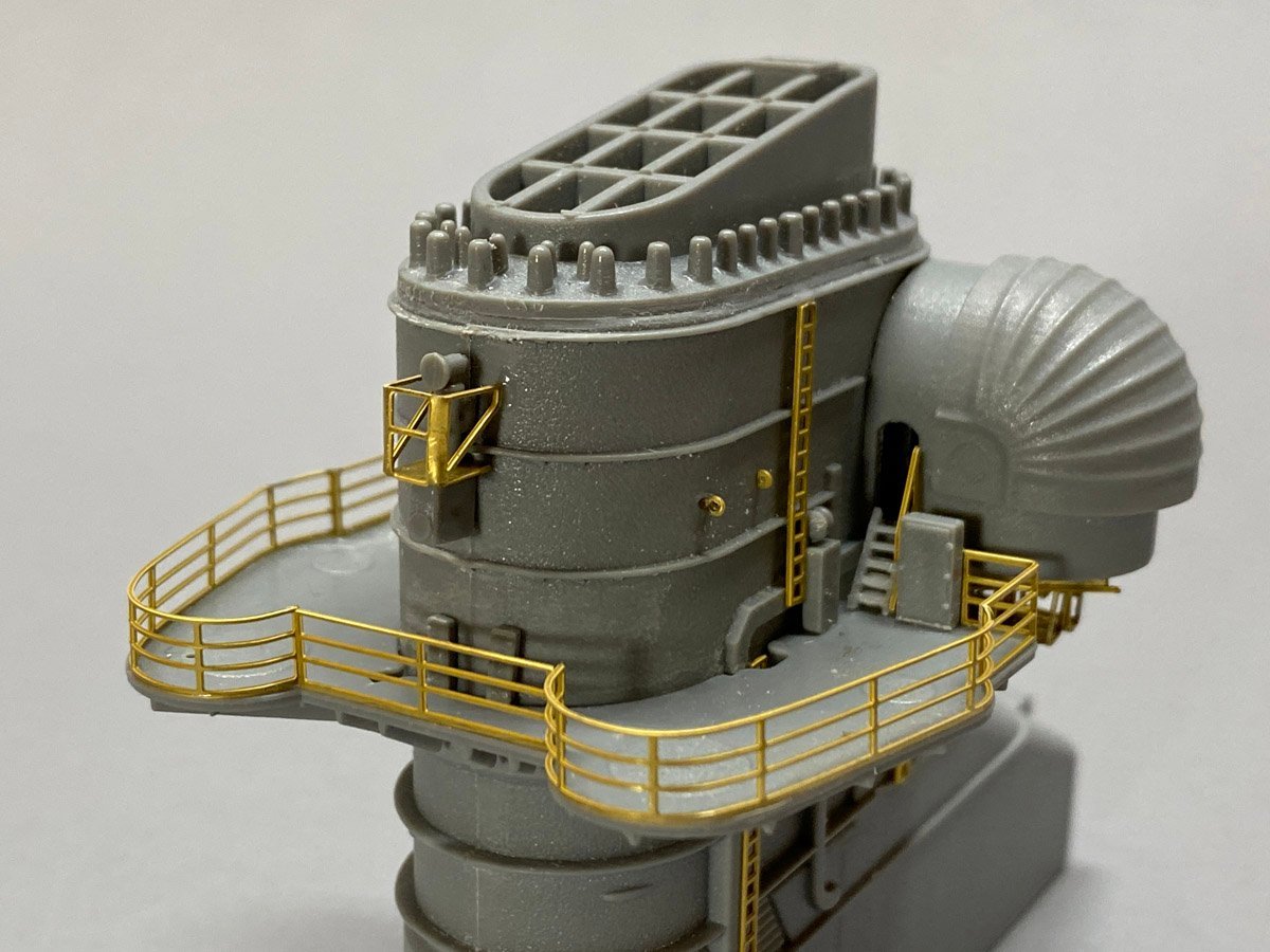
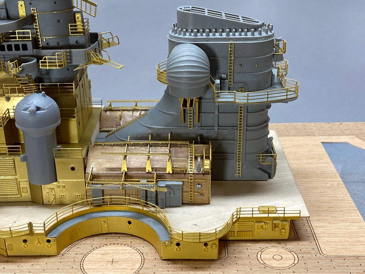
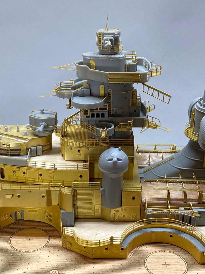
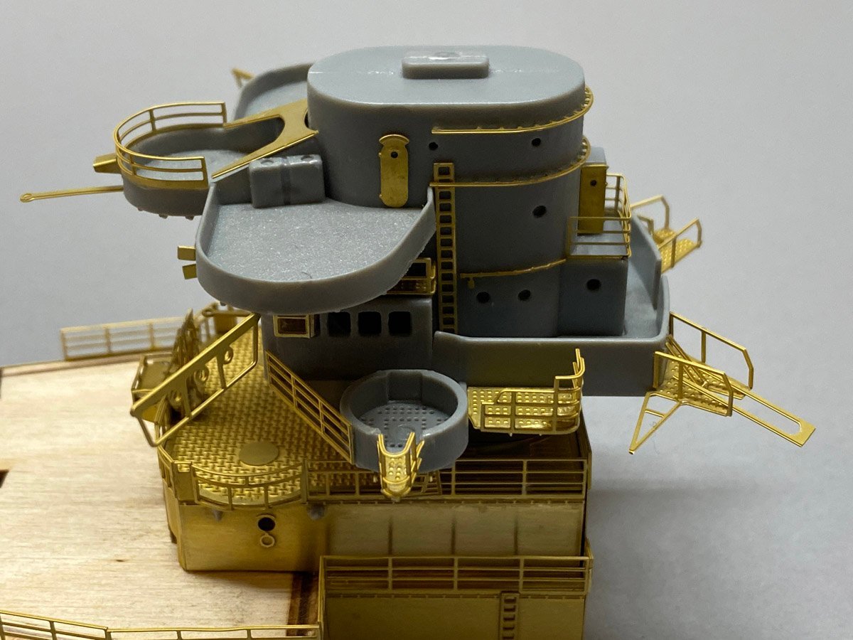
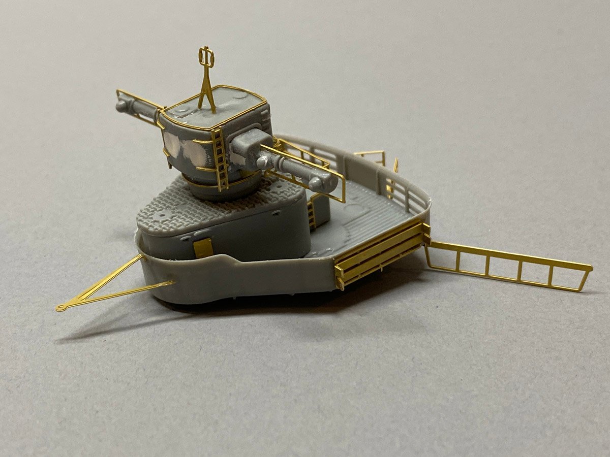
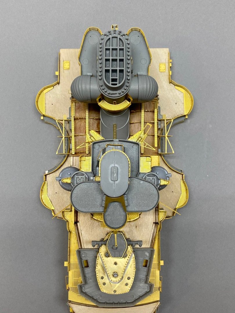
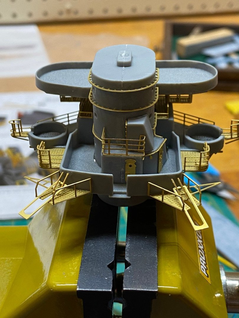
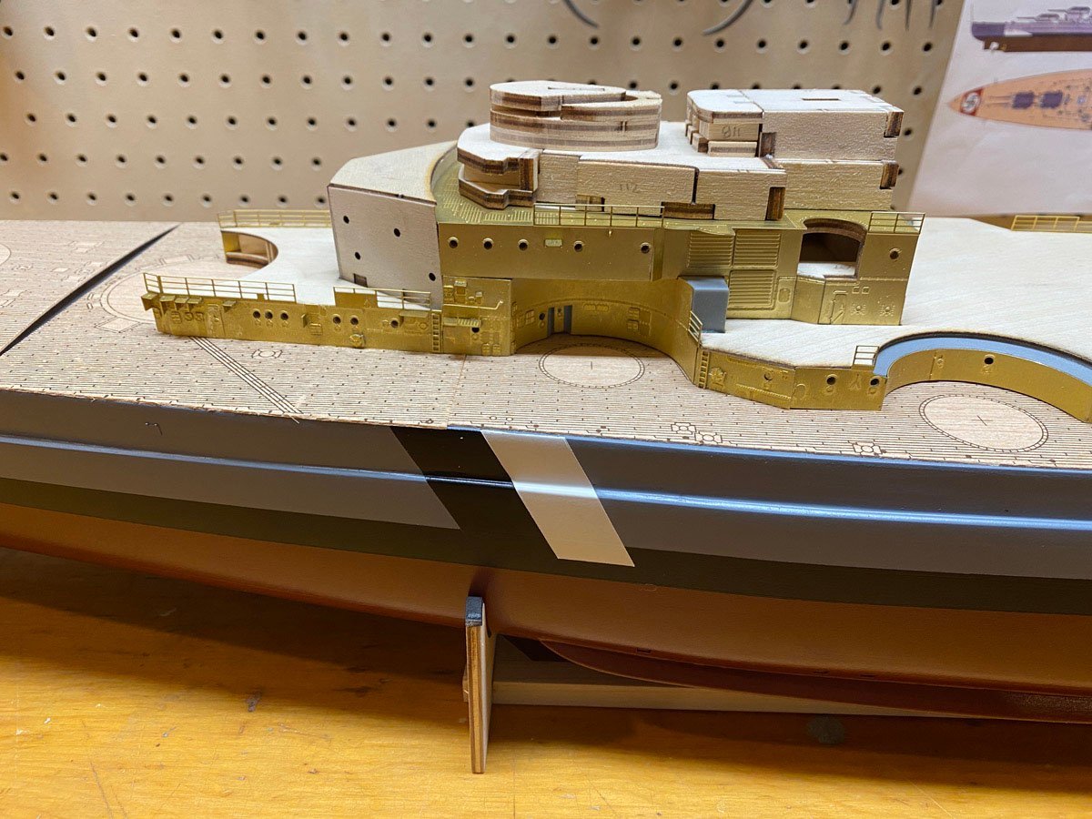
Forward Superstructure The forward superstructure is done to the point where I have to start painting. So of course we're expecting a major blizzard tonight and my car is safely in the garage where I'd like to paint. Anyway, here's where things stand. Overview This conning deck had very weird construction. It is built with a U-shaped groove between the top pieces. A piece of curved PE is dropped into the groove, then the groove is filled in with what ever putty you have. I'm still not happy with the putty. It would be so much easier to just laminate two pieces. I'm not much of a plastic modeler and don't know what's considered good moulding and what's not, but I think the plastic parts with this kit are not great. There's not much flash, but many parts have dimples where the plastic shrunk while cooling. This range turret had severe dimples that required filler. Now it looks like a little robot head on top of the Bismarck. The funnel was relatively easy to build. My Prinz Eugen model came with 2 blocks of wood to carve. It didn't have any of the myraid auxiliary pipes shown here, but I bought a brass detail kit made by Pontos for some plastic 1/200 Bismarck. Every pipe was a tiny piece of turned brass, and I glued them all individually. This was a lot easier. I love the details on this model. If you were Ant Man you could walk all around the decks. Front view with the little robot head on top. Back view. I have also finished the aircraft cranes but forgot to attach them for the photo. Fairey Swordfish view of the Bismarck.


-
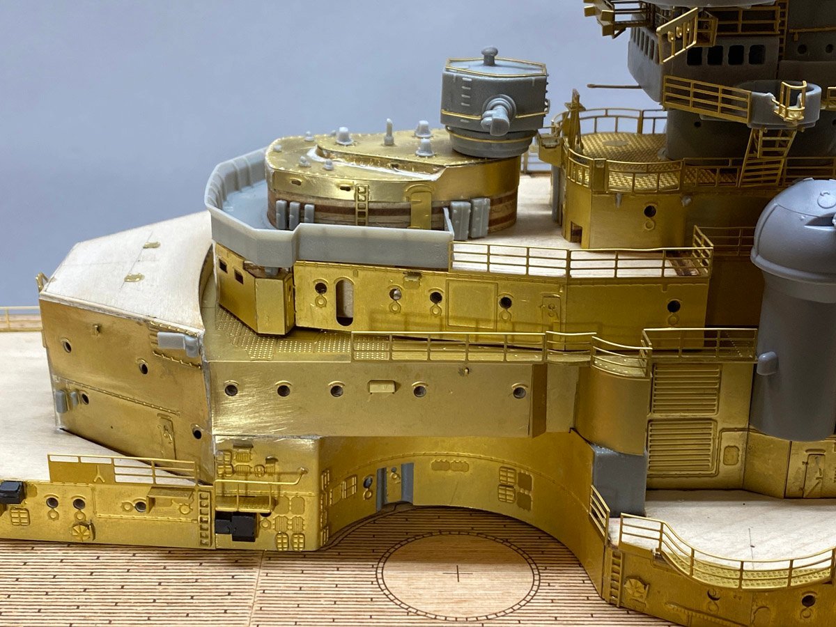
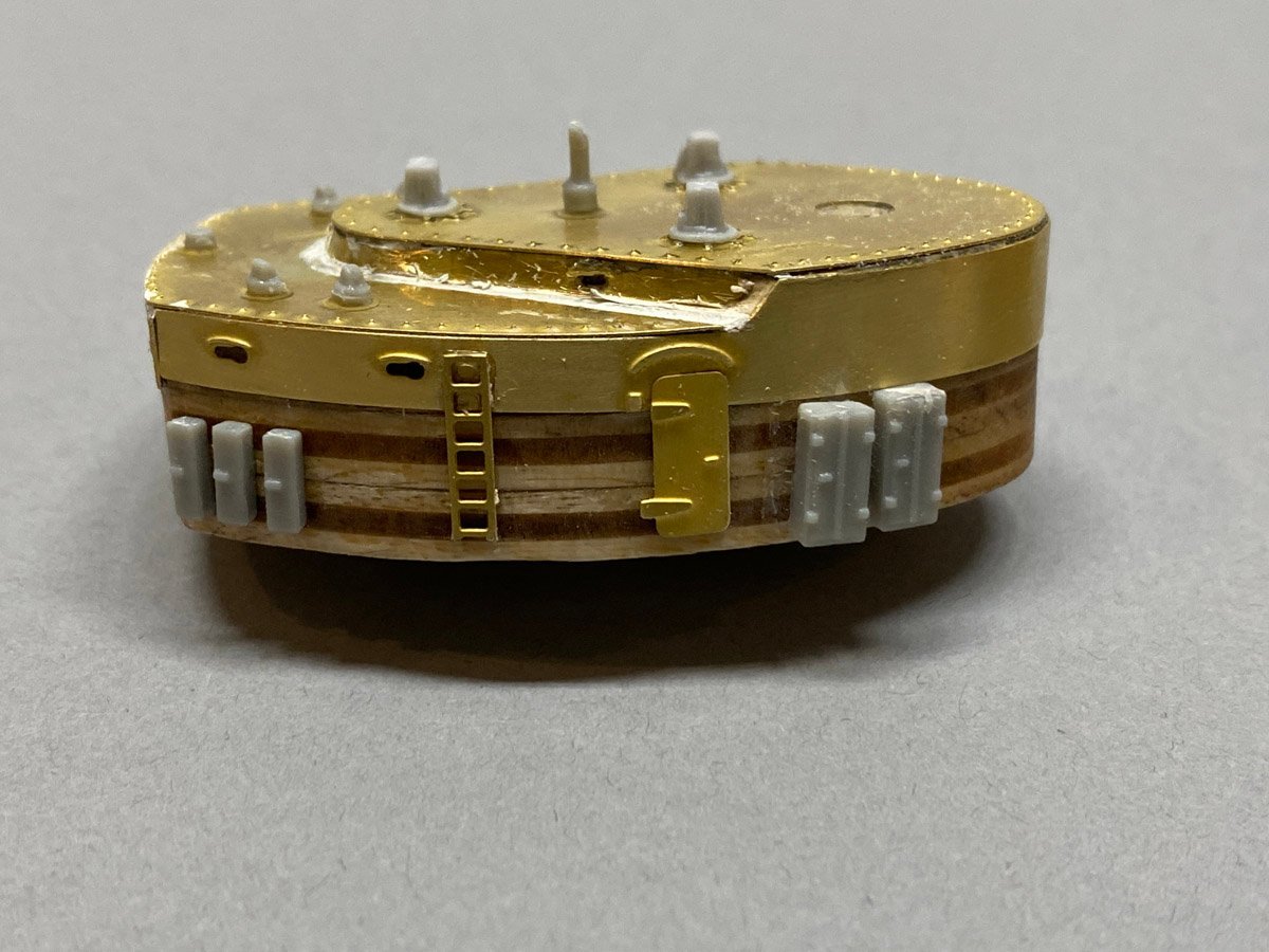
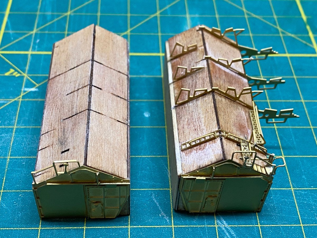
Admiral's Bridge & Hangars I've been very busy building forward superstructure, funnel, and hangars. Here's the start of the Admiral's bridge. Yesterday I started on the hangars. They were bigger than I expected, but also much harder than I expected. The framework is a mix of thick ply, thin ply, and particle board. I thought that I could just CA the pieces together while holding them against a square block of wood, but the joints are all loose because of the laser cut. My first hangar came out square but didn't sit flat. I had to break it apart and start over. The tops and one side of the hangars are thin ply with tiny cuts for brass inserts that must all be aligned. I got the first one reversed and had to break it apart and start over. Then I started to add the PE, but the thin ply sucks up the CA before you can get the brass in place. Last night I went to bed very disappointed with my first hangar. Today I remembered an old trick and wiped hangar number 2 with shellac. I just used a paper towel and it was dry in a few minutes. The shellac seals the ply and makes the CA stick much better. After that everything went together easily.
-
Harry, I love the in-progress photos of the mast with all the microscopic PE pieces laying around. It always make me wonder if I really need to attach all that stuff, but in the end I'm always glad that I do. By the way, what's the tug in the background in some of your photos?
-
One of those foam sanding pads around 220 grit will remove the razor blade scratches and leave the brass nice and shiny. Another thought: A top view of the Bismarck shows that the tops of many components were painted dark gray -- turrets, range finders, gun barrels, etc. You might consider painting just those things for some contrast.
-
Gentlemen, Thank you for all the tips on plastic cement. I tried to glue my funnel halves together with Tamiya liquid cement but the glue evaporated before I could paint the entire perimeter. I switched to Testors liquid, which worked better due mostly to the bigger applicator brush. I had to clamp the halves together for a couple of hours to get a solid joint but hated to wait. I am too used to the instant gratification of CA. I did find a workaround for using CA on the plastic. Now I swab one of the pieces with CA accelerator using one of those disposable micro paint brushes, then paint the second piece with CA from a toothpick and apply quickly. Seems to work well.
-
Plastic Glue Questions I am currently building the funnel, which is all plastic with PE details. I don't have much experience with plastic modeling and could use some advice from Old Collingwood or another plastic modeling expert. I am finding that my usual CA glue doesn't work very well with the plastic supplied with this kit. On the plastic the CA takes much longer to harden than it does for brass or wood. Plastic-to-brass is very slow - 20 seconds after application the parts are still sliding around, although they do set up eventually. I hate to spritz these tiny parts with a big blast of CA accelerator. Should I be using a different kind of glue for PE on plastic? What about large plastic-to-plastic joints like the sides of the funnel?
-
OC., A bit late but I just discovered your photos with the coins and your glasses for scale. Now I am more impressed than ever. Beautiful work sir!
-
I was looking at your model and wondering "How is he going to paint that?" Then I remembered your earlier post. I can see why you'd want to leave the model au naturale. The raw brass is attractive, and the contrast with the gray plastic and the wood really shows how much work you've done. My brass is already heavily tarnished, so you might want to get that matte coat on it soon. My brass also has a "few" spots of CA on it, that I hope I can hide with paint.
-
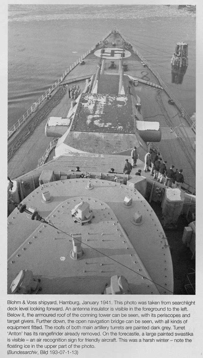
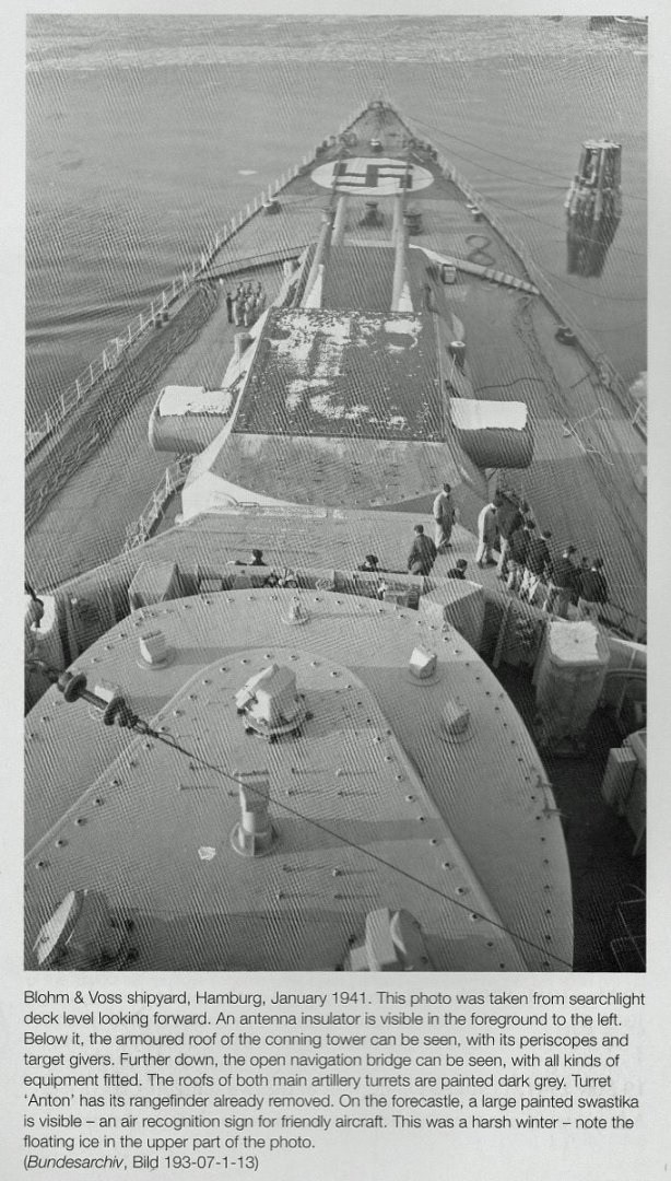
Harry, My instructions say that "The shapes of the planks must be slightly smaller than the decks leaving a border all around it which will later be used for the assembly of the handrail stanchions." It does not say how big the gap should be. Here's a photo of the Bismarck fore deck from "Anatomy of the Ship The Battleship Bismarck" by Stefan Draminski. It pretty clearly shows a gap between the planks and the edge of the deck, with handrails in the gap. My guess that the gap is 9 inches wide, or about 1.1 mm at our scale. So I'd say to shave a tad off your decks. That said, my gap varies from 1-3 mm around the edge. I haven't looked at the stanchions yet and don't know how deep I'll have to drill, so I hope that they don't poke through if they're too close to the edge.
-
I hate it when that happens! It's usually not as bad as you expect. Take a deep breath, and an hour or two later it's almost as good as new.
-
Ted, You did a great job on the ammo elevator. It took me 3 or 4 hours to build that tiny thing.

-
Thanks for the warning. Looks like your page numbers should be Pages 131 and 133 of Volume 2.
-
Harry, There is a slight space between the printed deck and the sides of the hull. It is not too uniform - it ranges from 1 - 3 mm around the perimeter. I had to remove a little from parts of the printed deck amidships to get a gap. I have not drilled holes for 170 stanchions yet (ugh), but I photocopied the printed pieces to make sure that I didn't lose the locations. Rod
-
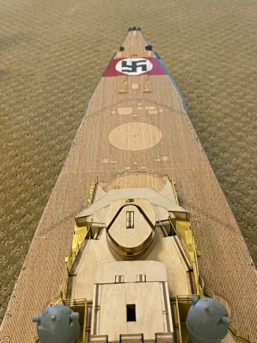
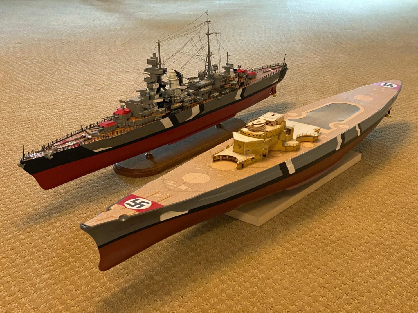
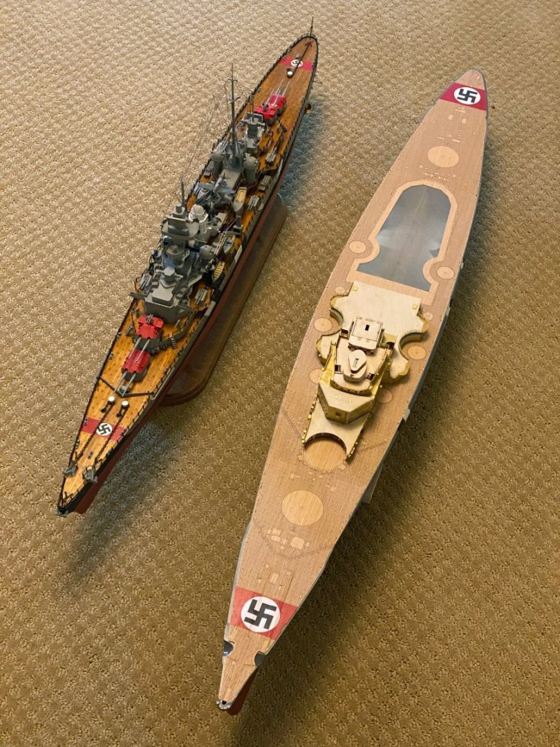
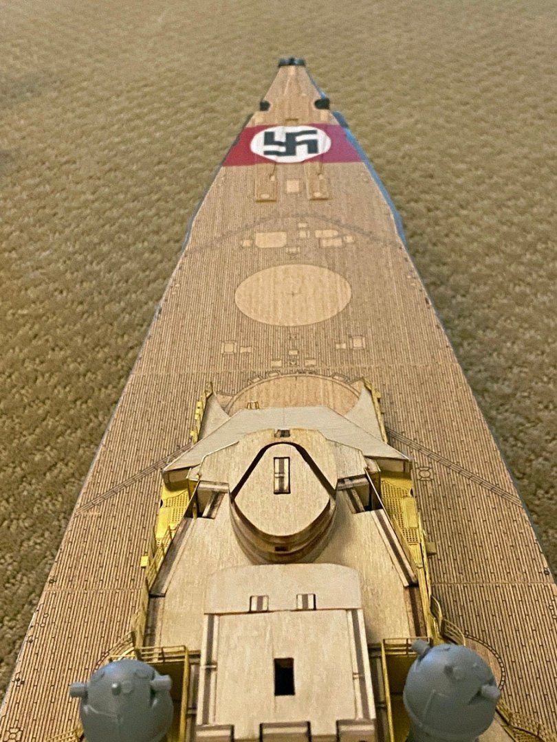
Prinz Eugen + Bismarck (in progress) My Prinz Eugen and the Bismarck are the same 1/200 scale and I've been dying to see them side-by-side. Here they are. I had forgotten how much STUFF there is on the Prinz Eugen. The Bismarck will be worse. On the Bismarck I finished the printed decks with several coats of Minwax satin Polycrylic spray. I taped and sprayed the red stripes before installing the decks. I had made swastikas in Photoshop for the Prinz Eugen, so I scaled them up for the Bismarck, printed them on self-adhesive mailing labels, cut out the white circles and stuck them on, then sprayed everything with Minwax again. I attached the decks with 3M Super 77 spray adhesive. You only get one chance with that glue but I've used it for many projects and got it right again. The Prinz Eugen came with a terrible printed deck so I planked my own with 5 mm basswood and finished it with orange shellac. It looks nice but the actual planks would be a meter across at 1/200 scale. That was the first of many deviations from scale on that model. The Prinz Eugen is what's known as "drive-by scale." It looks good from a car driving by slowly.
-
Ted, You've got the hang of the PE work - it looks great! I am a big fan of Proxxon tools. I use their pen sander with 80 grit paper to even up wooden frameworks, and with 400 grit paper to clean the nubs off all the PE parts. I keep a tip loaded with each. Their self-adhesive sand paper is terrible so I make my own with 3M double-sided tape and high-quality sand paper. Cleaning nubs off PE eats up the 400 grit paper and I go through several squares every day, so I make up several strips about 6" long and cut off a square as needed. Proxxon's 5" disk sander with 120 grit disks is good for removing a line of brass from PE cladding that is just a hair too big. Rod
-
Ives, I just received my October, 2021 issue of Model Boats magazine. Isn't the postal system great? Anyway there is an article entitled "3D-Printed Flower Class Corvette" by Benjamin Eng, owner of bensworx and designer of your model. He gives an excellent overview of the design process, but the photos of his unpainted model are not nearly as nice as yours. The same issue has another article entitled "3D CAD for Modellers" by John Parker that gives some tips on CAD software. That article is followed by one explaining the different ways in which water and smoke tube boilers work. I love that juxtaposition of old and new. Now get back to work on the Corvette! Rod
- 321 replies
-
- 4
-

-
- Finished
- Flower-class
- (and 1 more)
-
Harry, Thanks for the links. Coincidentally I just finished that section a couple of days ago. I did look ahead to see what deck areas get brass, print wood, or left as plywood. I thought that I might need to seal the plywood areas, but the wood is already very smooth and it gets painted a dark gray. I think it will look fine without the plastic card. Rod
-
Harry, Thanks for the "heads up" but I'm not sure what area you're referring to. Would it be possible for you to post a photo of that area? Rod
-
Ted, I am using the 10mm Tamiya tape that you had problems with. My only "trick" is to burnish the edge A LOT with the round barrel of a Sharpie pen. I used 3/4" Scotch masking tape for the false bow & stern waves. I didn't bother with the templates supplied with the kit. To be honest, my stripes required 2 iterations. I did the white first, then tried to selectively remove tape and paper, and re-tape the black areas. When I was done painting black I removed the masks and discovered 3 black stripes over top of white. I had to re-tape all the white and re-paint. In technical terms, it takes a ZILLION coats of white to cover over black.
-
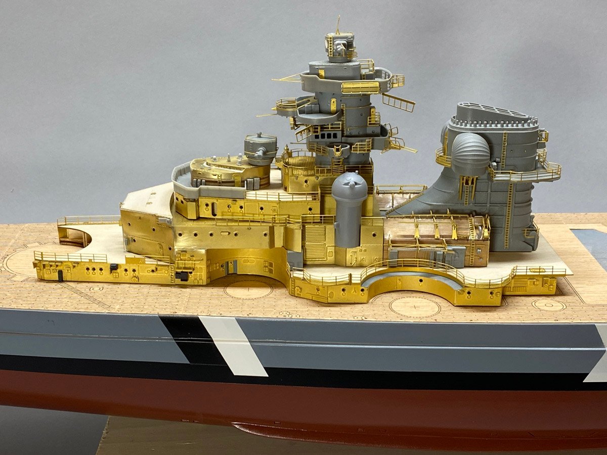
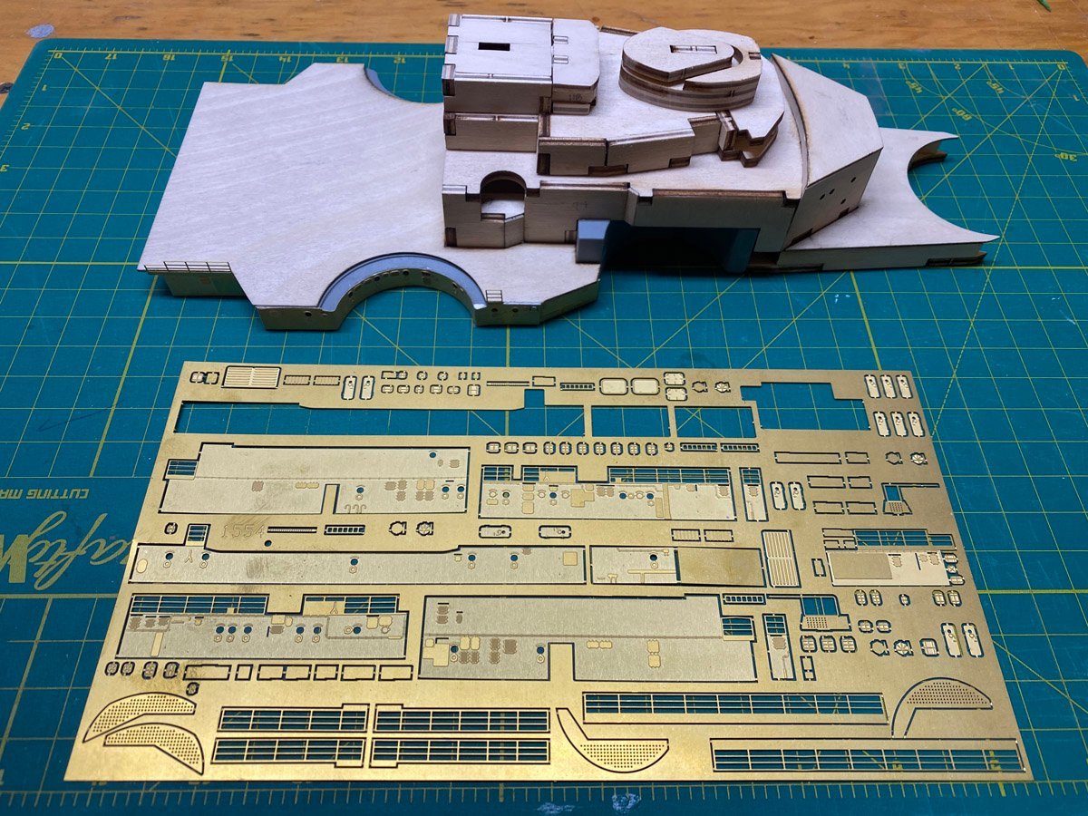
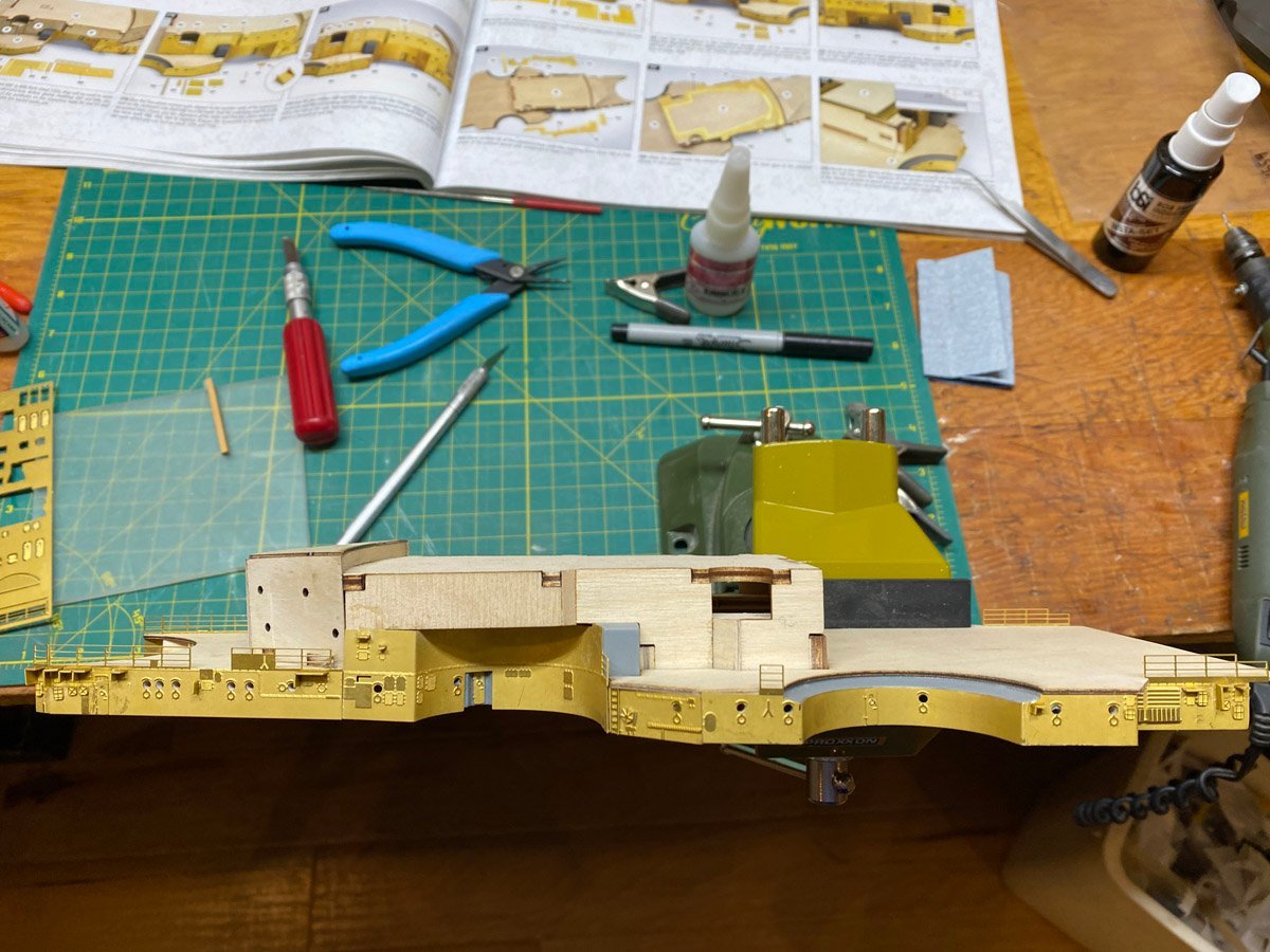
Superstructure -- 150 hours, 76 days While waiting for paint to dry I've been building parts of the superstructure. The construction technique is all new to me - complicated plywood frame and some plastic components, all skinned with photo-etched brass. The instructions are excellent and the brass parts are numbered almost sequentially on the sheets, making them easy to find. It helps to secure the structure in a vise to keep from breaking off the delicate details. You can only bend a PE piece 3 times before it snaps. (Don't ask how I know.) Amazing how the shiny brass is covered with fingerprints after just a few days.

- 215 replies
-
- 10
-
-
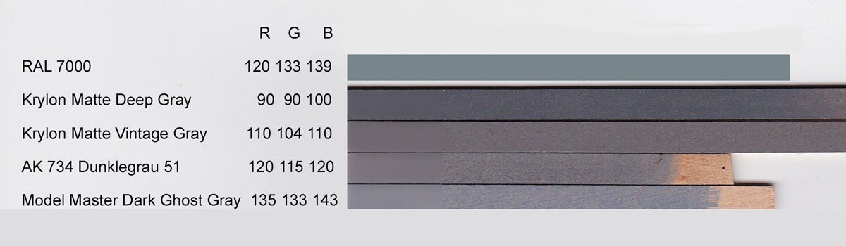
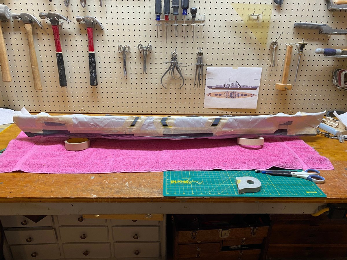
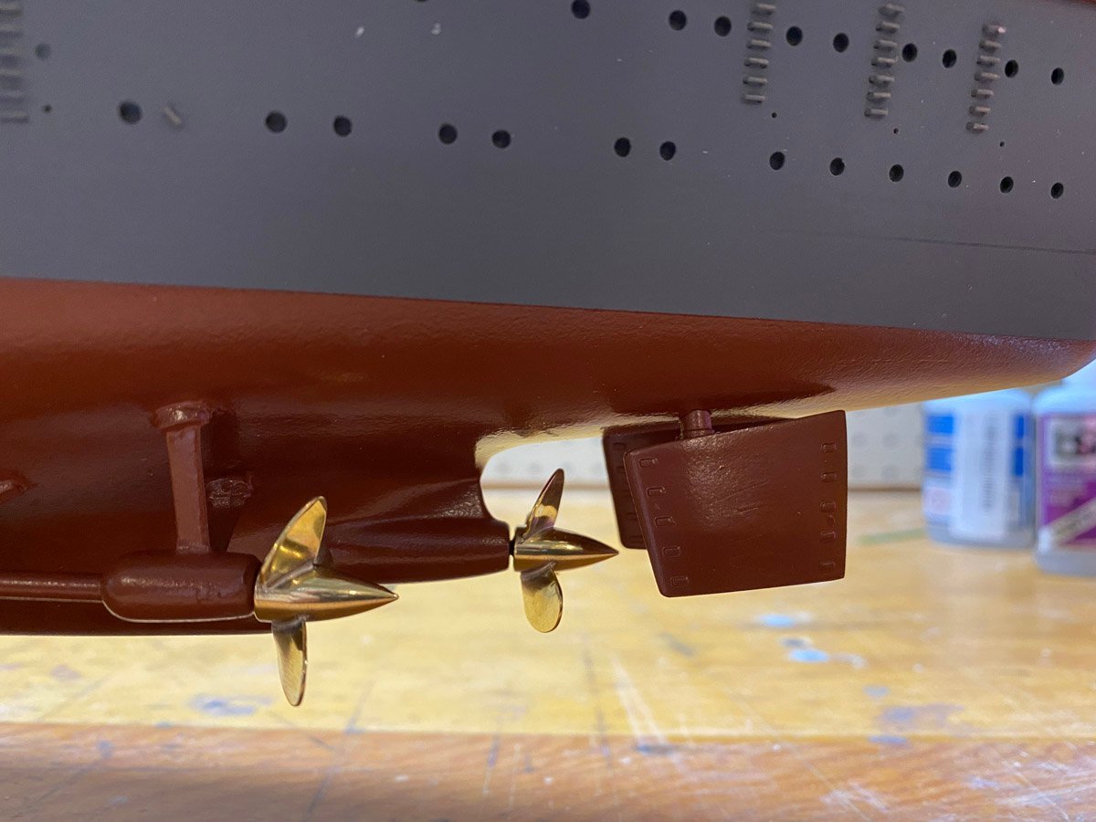
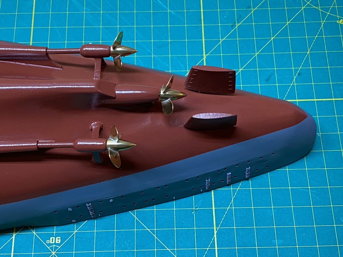
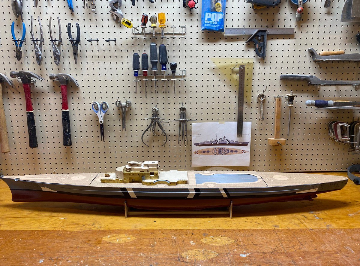
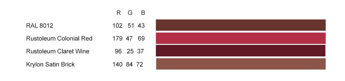
Color Schemes I've never built a model where the colors were given exactly. The Amati instructions specify RAL colors, a German color-matching system. I made up color charts for the hull using paints that I have used. For the grays I painted some samples, scanned them, then averaged the pixels and got the RGB colors using Photoshop. For the reds I used color swatches from the Krylon and Rustoleum web sites. Here's what I found. Upper hull, RAL 7000. I had 4 kinds of gray paint and thought that surely one would work. Wrong. RAL 7000 is fairly light but has a lot of blue in it. Lower hull, RAL 8012, almost a brick color. I used Rustoleum Colonial Red on my Arleigh Burke, my Prinz Eugen, and even on a couple of stationary steam engines. I used Krylon Satin Brick on my Marie Felling. Ted99 is is using Rustoleum Claret Wine on his Bismarck. It is actually pretty close to RAL 8012. I ended up ordering cans of acrylic spray RAL 7000 and RAL 8012 from LVP Paints. It was fairly expensive and the postage cost more than the paints, but it arrived quickly, sprays perfectly, and looks great. Partially painted with temporary pedestal base. I couldn't tolerate plastic props on a $700 model so I ordered brass Raboesch props from agesofsail.com, two left and one right. The props and rudders are not attached yet. Masking for the white dazzle camouflage. Good thing I just had all that practice wrapping Christmas presents. Hull painting completed save for some minor touch up. Back in its cradle for now.

-
Harry, It seems that the Hachette model has plywood pieces at the bow and stern drilled for Rivet porthole thingies. You omitted the plywood but installed the rivets. Is that correct? The Amati model has PE brass pieces that fit over the plywood, but no rivets. I got the PE pieces reversed so the tiny raised detail for the portholes doesn't show. I am getting ready to paint the hull, saw your rivets, and wondered if I missed something. Rod
-
Beautiful work Ted! Too bad about the matte white. It's always the paint that causes trouble. Rod