HOLIDAY DONATION DRIVE - SUPPORT MSW - DO YOUR PART TO KEEP THIS GREAT FORUM GOING! (Only 20 donations so far - C'mon guys!)
×


rvchima
-
Posts
697 -
Joined
-
Last visited
Content Type
Profiles
Forums
Gallery
Events
Everything posted by rvchima
-
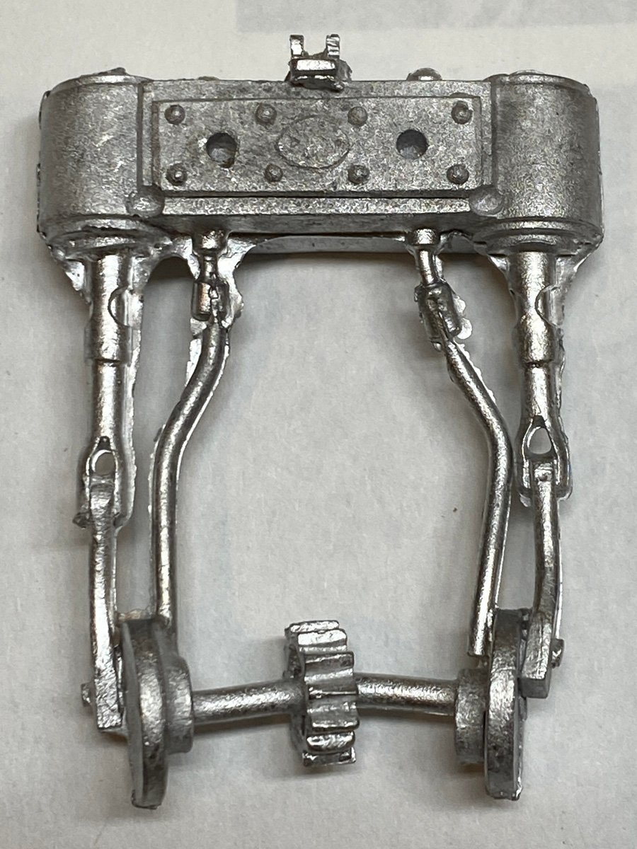
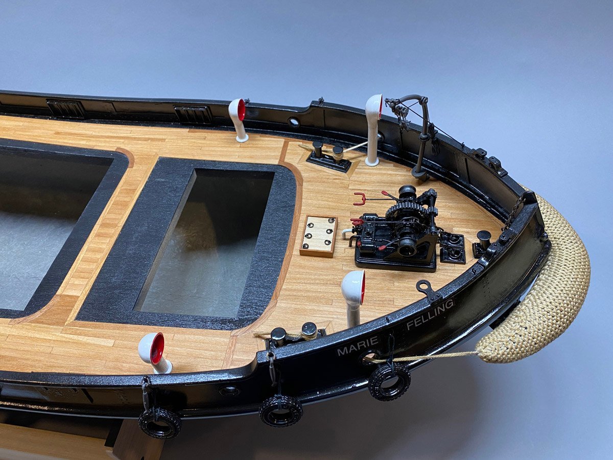
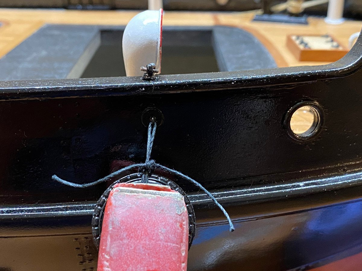
 A Bunch of Photos Before Final Assembly - Hull The rope fender is by Caldercraft. I soaked it in coffee to darken the color. Now my ship smells like a Starbucks. I made the Marie Felling text using a Brother label maker, white on clear. You can see the clear if you look closely but it's not bad. The tires are by Amati. They seem small to me but at 1:32 scale they are about thee size of the tires on my Honda CRV. I held the line with a spring clamp while I tied them in place. Power steering! The ship had a small steam engine inside a cabin that will be installed at the right. It drove chains that looped around the aft deck, through a couple of "spring boxes", and to the tiller under the grating on the left. The steam engine was controlled by the ship's wheel. Mistake 1: I installed the aft grating long before the steering chains, so I had to fish the chains underneath and pin them through the grating. Mistake 2: The pulleys each comprised 3 cast pieces that I cleaned up, painted, and assembled. Then I discovered that the supplied chain didn't fit. I eventually glued the pulley wheels solid and drilled out one side to fit the chain.
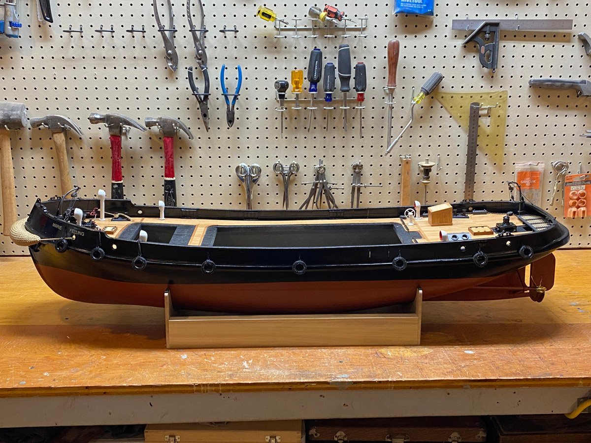
- 50 replies
-
- 5
-

-

-
- Marie Felling
- tug
- (and 3 more)
-
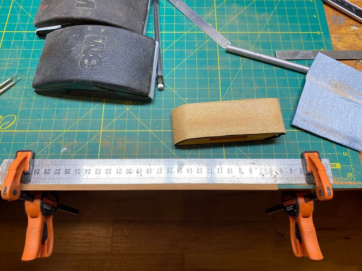
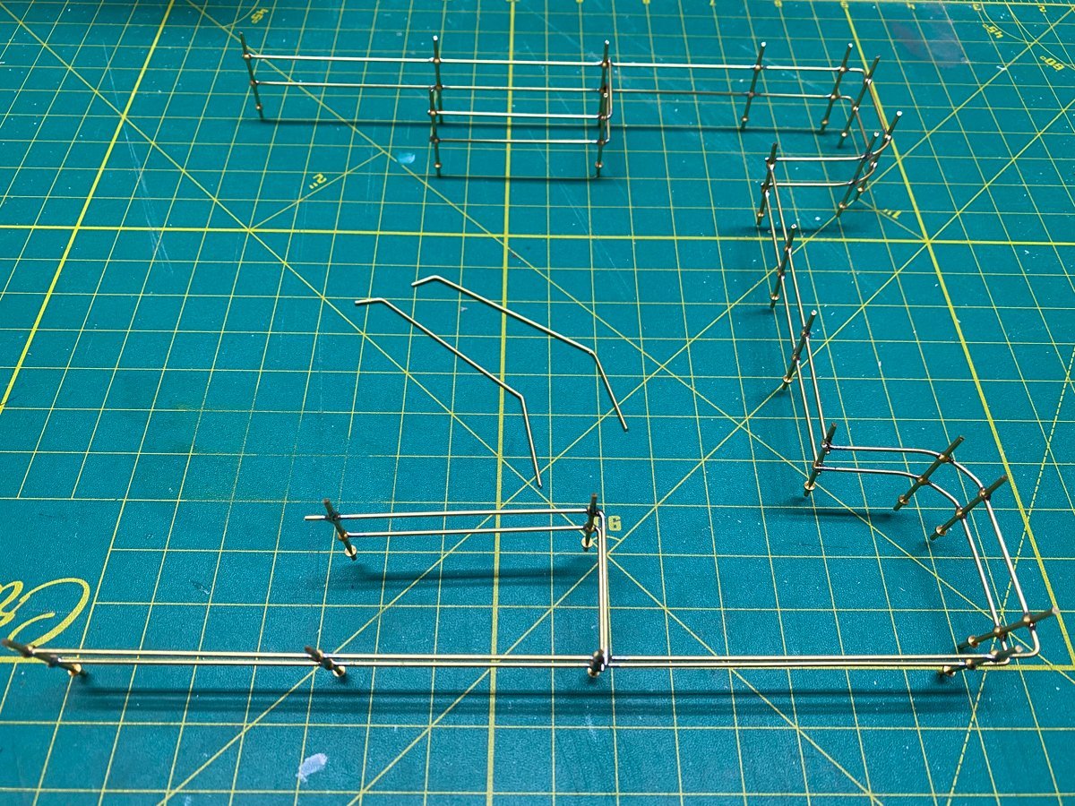
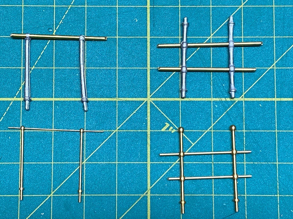
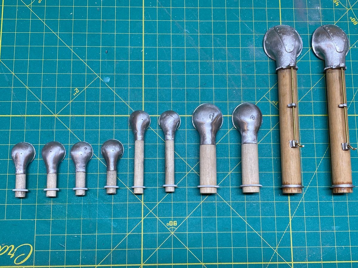
Stanchions and Railings The kit includes single-ball stanchions for the searchlight deck, 2-ball stanchions for the main deck, and lots of nice, 1.5 mm diameter brass rod. Every build log mentioned above says that that the cast metal stanchions are just too flimsy, but one builder said that his kit came with brass stanchions, and another managed to buy replacements. Caldercraft does sell brass stanchions the correct height so I ordered some a while ago. I ordered 3-ball stanchions for the main deck, planning to cut off the top ball and cap it with a wood railing. When it was time to install them I discovered that the 3-ball stanchions had 1 mm holes, and the single-ball stanchions have .02" (.51 mm) holes, both too small for my brass rod. I ended up buying more brass rod the correct diameters. Here's a sample of the cast stanchions at the top and the brass stanchions below. I drilled mounting holes in the deck and assembled the railings in place. I lifted the entire rail assembly from the deck and sprayed it separately. The cap rails were made from some scrap mahogany using this jig to hold each piece while I rounded the edges.
- 50 replies
-
- 6
-
-
-
- Marie Felling
- tug
- (and 3 more)
-
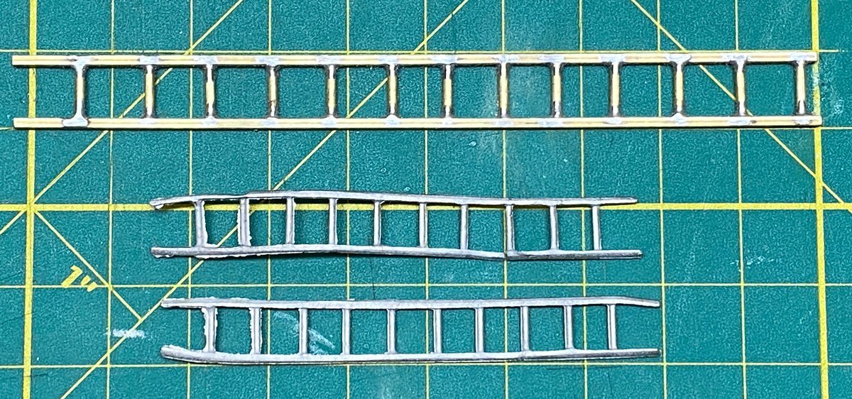
Searchlight Deck Ladder The cast metal pieces for the ladder to the searchlight deck came out of the molds bent, cracked, and with lots of flash. I thought it would be easier to build my own from some square brass tubing and brass rod. It came out pretty nice.
- 50 replies
-
- 2
-
-
- Marie Felling
- tug
- (and 3 more)
-
Yves, This looks like an amazing kit. I suppose that you need something to do while your 3-D parts are printing! I had never heard of CAF models but a quick search turned up their copyright infringement issues. I'm glad that they got it sorted out. Are you concerned that they might disappear before you get all five sessions? Rod
-
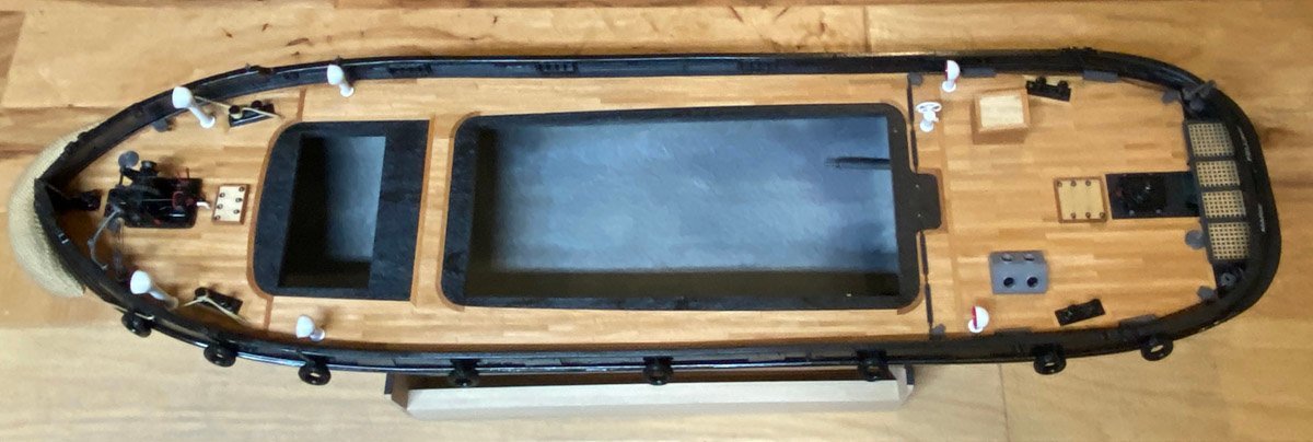
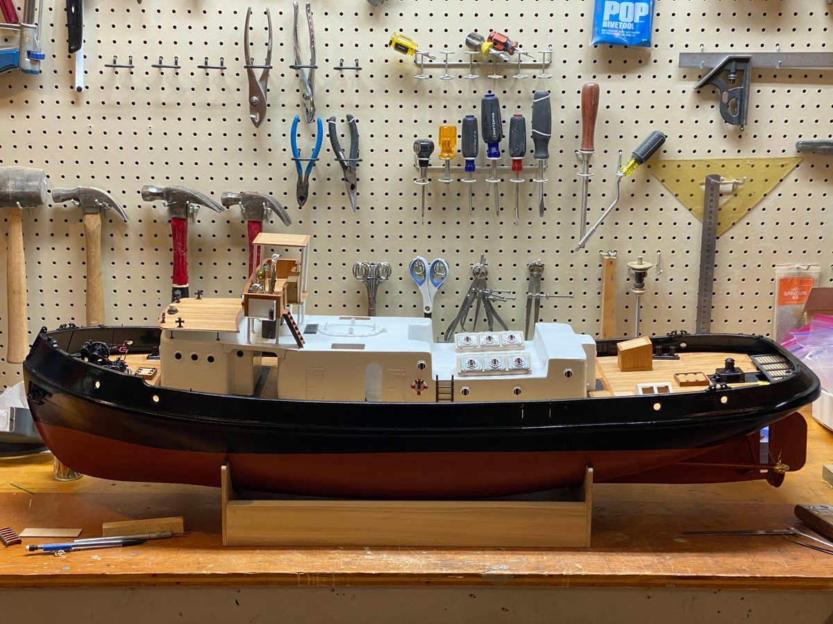
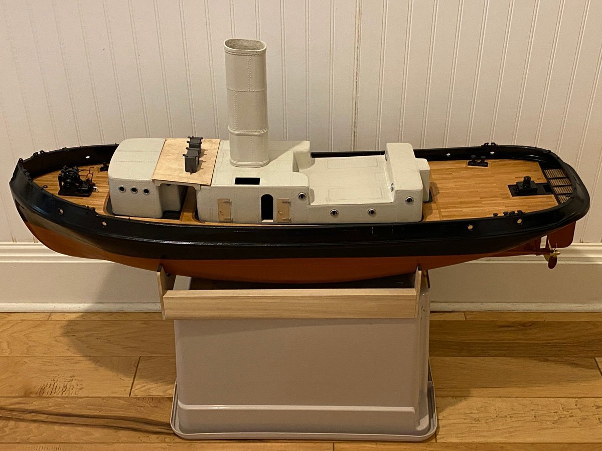
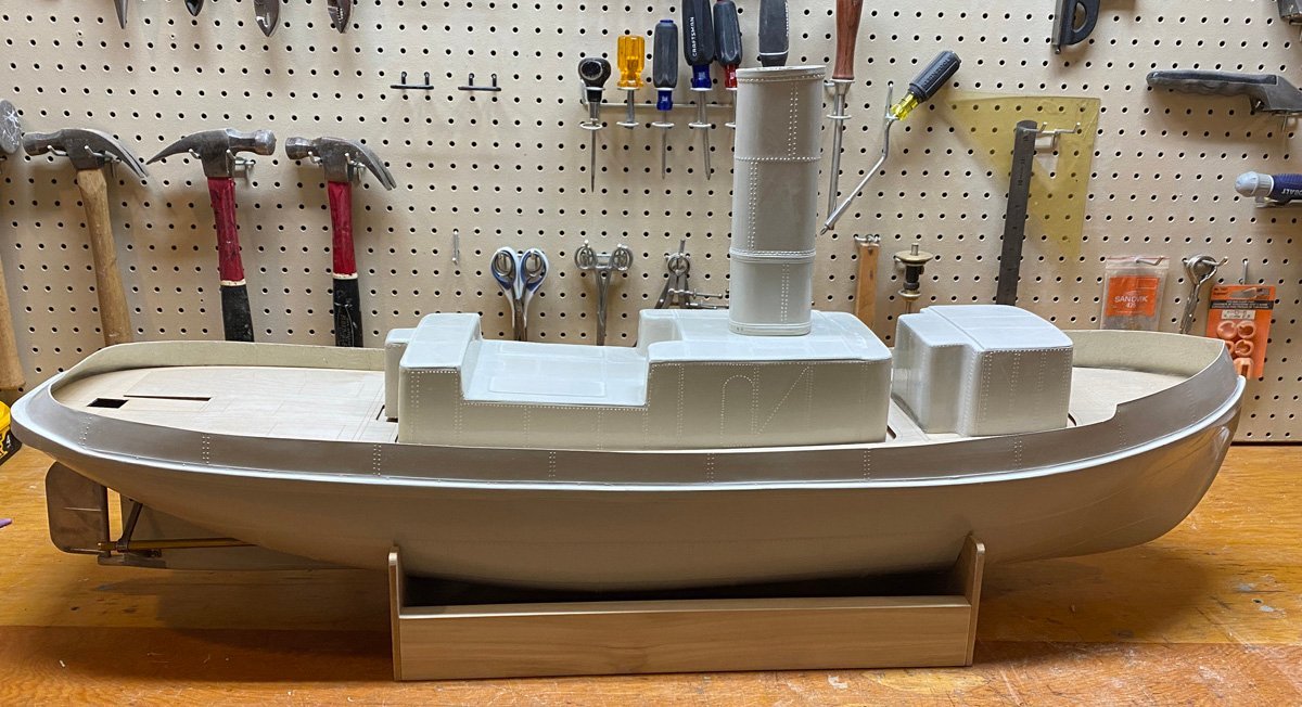
Making Progress But More to Do Here's everything stacked up. You can see the boat deck attached to atop the forward cabin now. Most of the small parts have been attached to the deck, but the cabins and bridge are all separate. Lest you think that I'm almost finished, here are all the parts that I still have to complete.
- 50 replies
-
- 5
-
-
- Marie Felling
- tug
- (and 3 more)
-
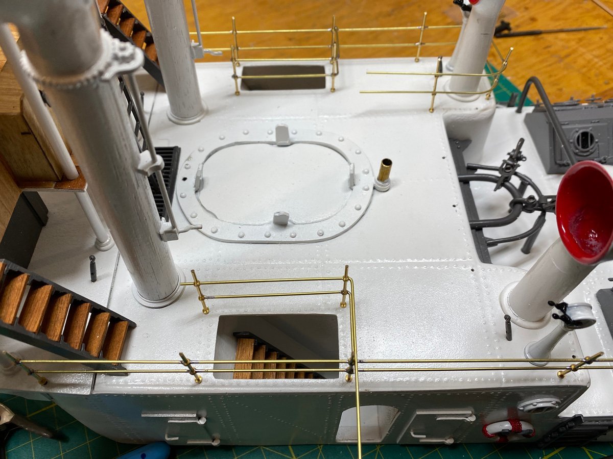
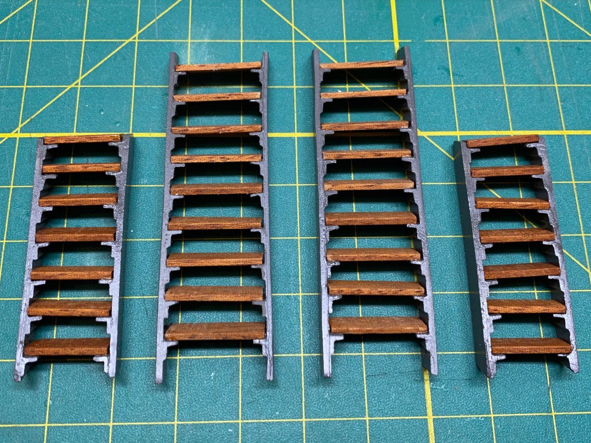
Miscellaneous Small Parts and Bridge, 195 hours Map and flag chest, two hatches, and stern companionway ready to spray. Four ladders with white metal sides. The kit includes laser-cut ply steps but I used some scrap mahogany. Parts for the skylights. I sure dreaded cleaning up all that white metal ... but it only took a few hours. Ten vents ready to paint. The kit has printed plywood for the bridge. I covered those pieces inside and out with cherry, and used more mahogany for the rails. There were obviously lots of other little parts to clean and paint.
- 50 replies
-
- 5
-
-
- Marie Felling
- tug
- (and 3 more)
-
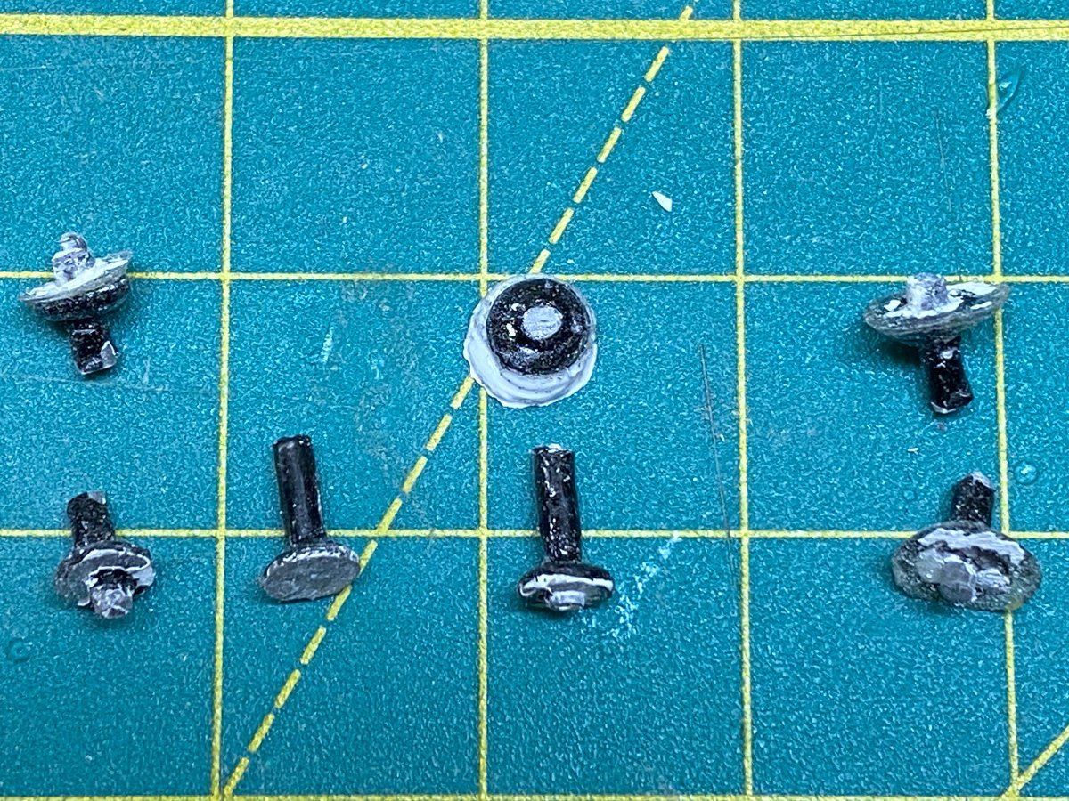
Note to Self: Don't Use White Metal for Structural Parts The forward cabin has a boat deck mounted on top with 8 little pillars made of white metal. I aligned the wooden deck and cabin, and carefully drilled the 8 holes through both pieces. Then I epoxied the pillars to the cabin, and later to the deck, and clamped everything lightly. Every thing seemed to go OK, but the next day, because of the curvature of the cabin, two pillars had snapped in half and two more had pulled away from the deck. After a few choice swear words I came up with an easy repair. First I cut the remaining pillars, separated the cabin and deck, and removed the pillar parts from the deck. I had to fill the holes and repaint the bottom of the deck. Next I filed the pillars remaining on the cabin down to the base, and drilled through the center to fit a narrow nail. I put nails into all 8 holes and flipped the cabin upside down over a narrow board on my bench, so that the nail heads were all level. Then I epoxied all the nails from the inside of the cabin. When that was dry I flipped the cabin upright and reglued the deck. Poor photo of some broken pillars. The cabin with new pillars made with nails. I'll post a photo with the deck in a minute. The kit comes with a big sheet of acetate for windows, but I painted some styrene black and glued it inside with RC cabin glue.
- 50 replies
-
- 3
-
-
- Marie Felling
- tug
- (and 3 more)
-
Yves, I just came across this log and want to join in on the fun. I will be following along. The model is just beautiful, and it's fascinating that everything is printed right there in front of you. Rod
- 321 replies
-
- 5
-
-
- Finished
- Flower-class
- (and 1 more)
-
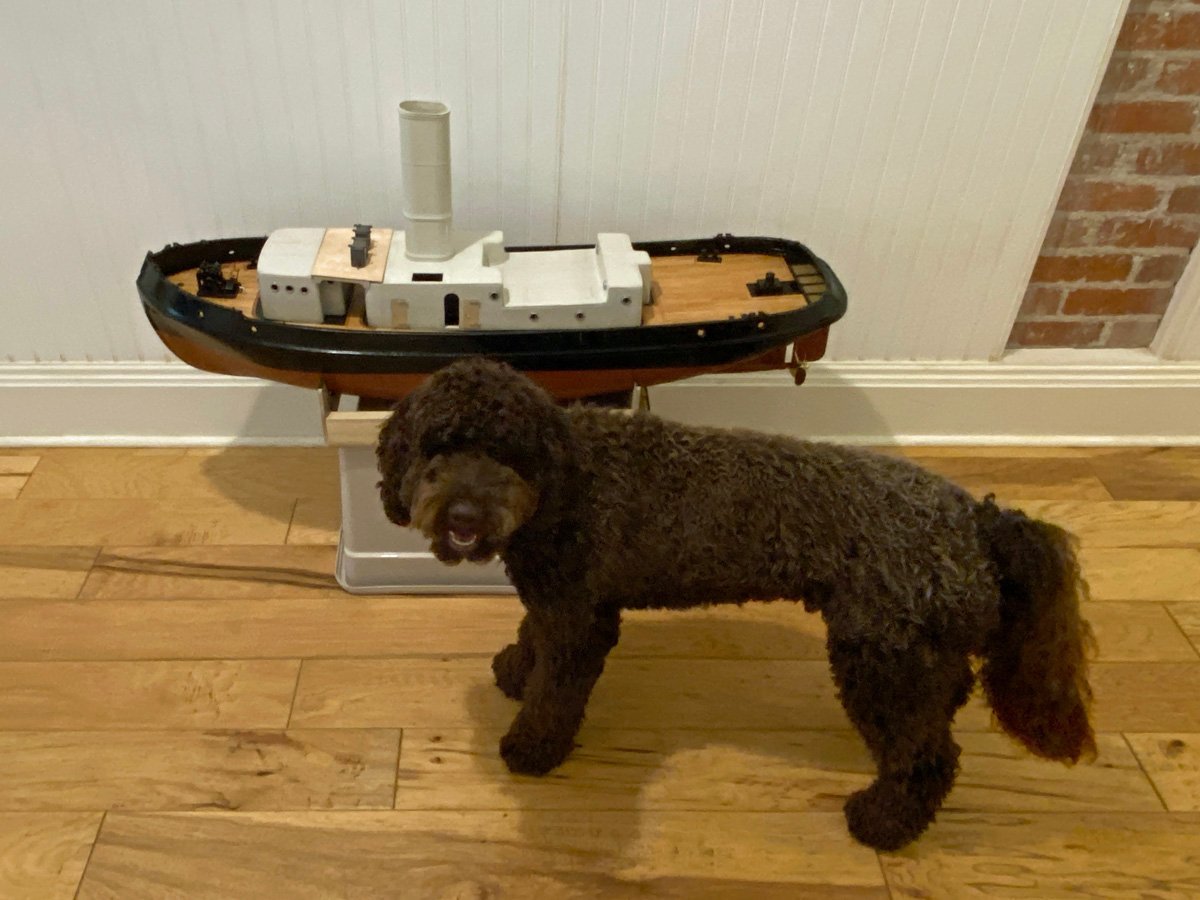
Moving Right Along, 117 hours Here is everything stacked up so far. It seemed like this was going pretty fast but then I looked at how many white metal pieces are left ... And here's my dog Loki admiring my work.
- 50 replies
-
- 7
-
-

-
- Marie Felling
- tug
- (and 3 more)
-
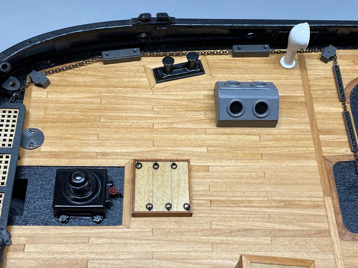
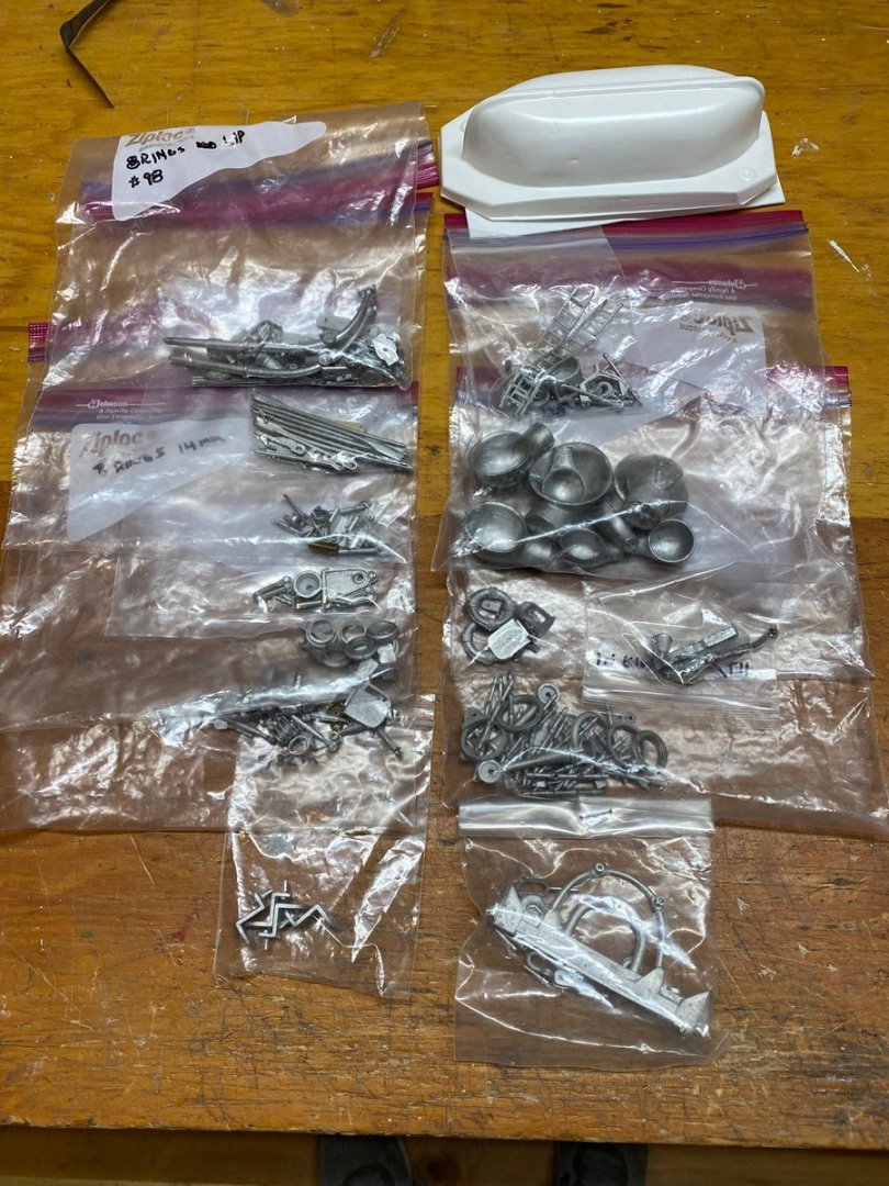
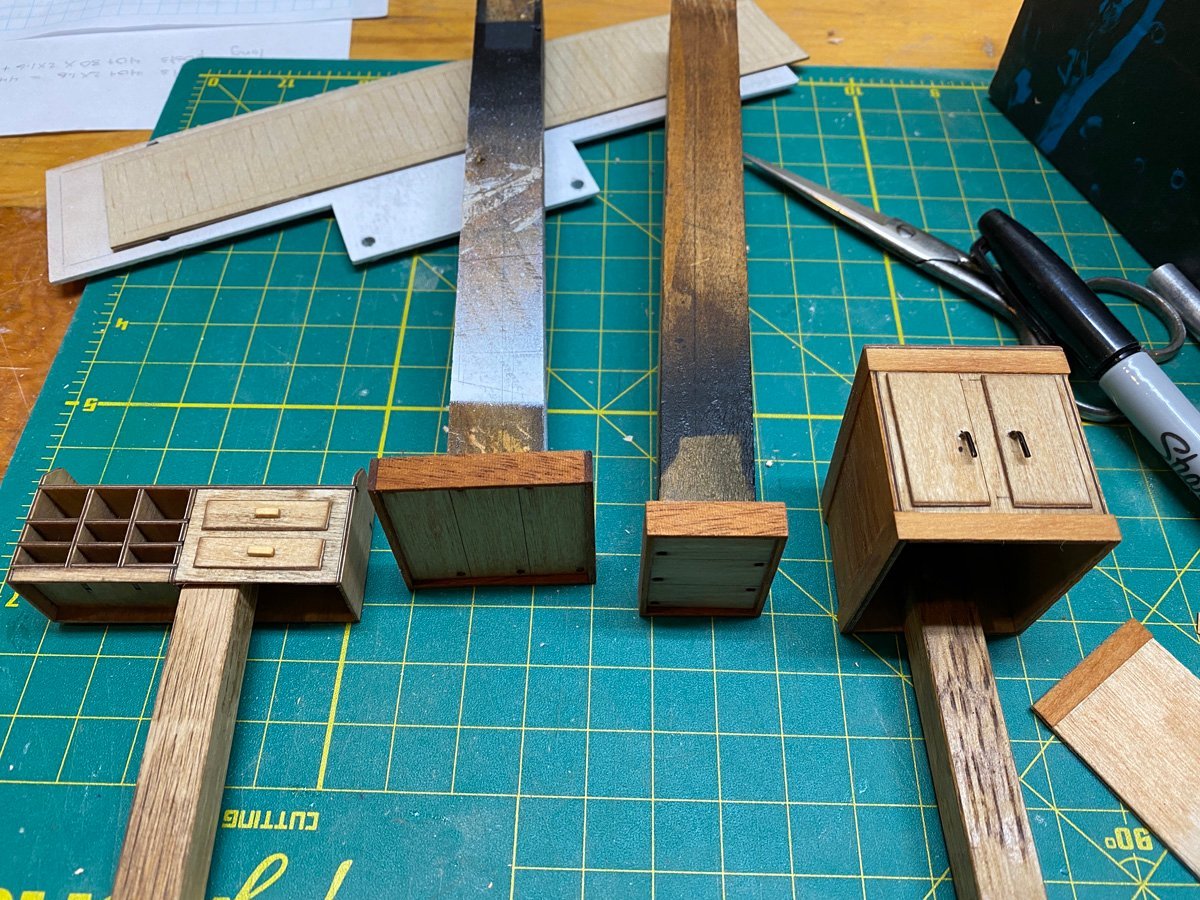
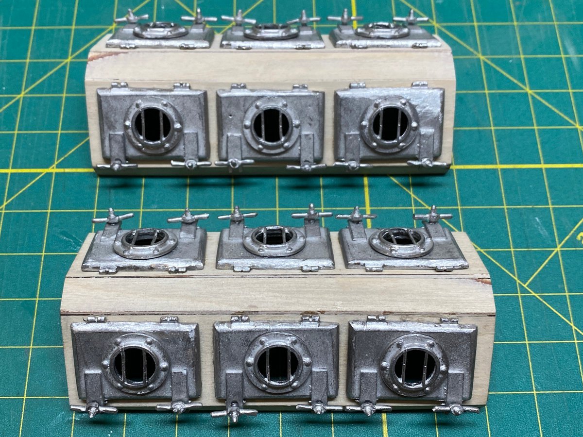
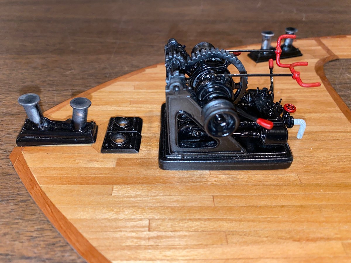
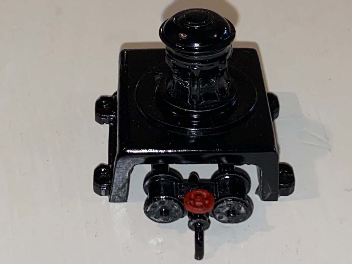
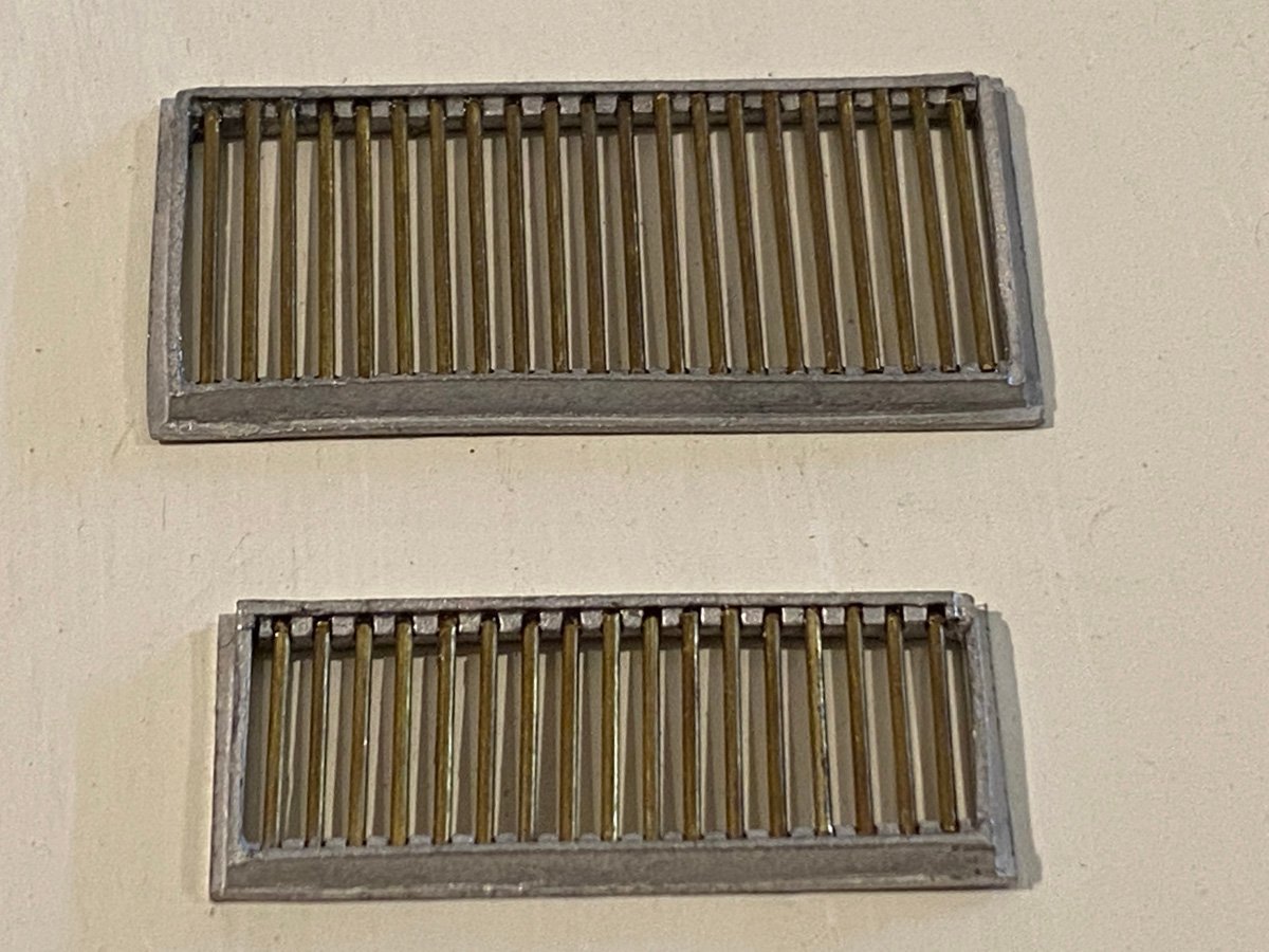
Miscellaneous Small Parts Caldercraft includes several mini-kits for various pieces of equipment. Everything is white metal, which often gets bent when it is removed from the mold. Or in shipping. Or if you look at it crossly. This steam engine for the capstan took a bit of straightening out and cleaning up. Here's the finished capstan. The anchor winch is very nice. I experimented with weathering the bollards but ended up repainting them. The instructions call for two water tanks to be made from certain blocks of wood. The parts list gives the dimensions for those blocks but none of the blocks that came with the kit were close. I had some white Azek trim in a good thickness and cut my own. The white metal straps were much too long so I built new ones out of styrene strips. The tanks were painted with a spray color called "Iron," which looks pretty convincing in reality. These two grates go in the top of the rear cabin. I'll probably paint these "Iron" too.
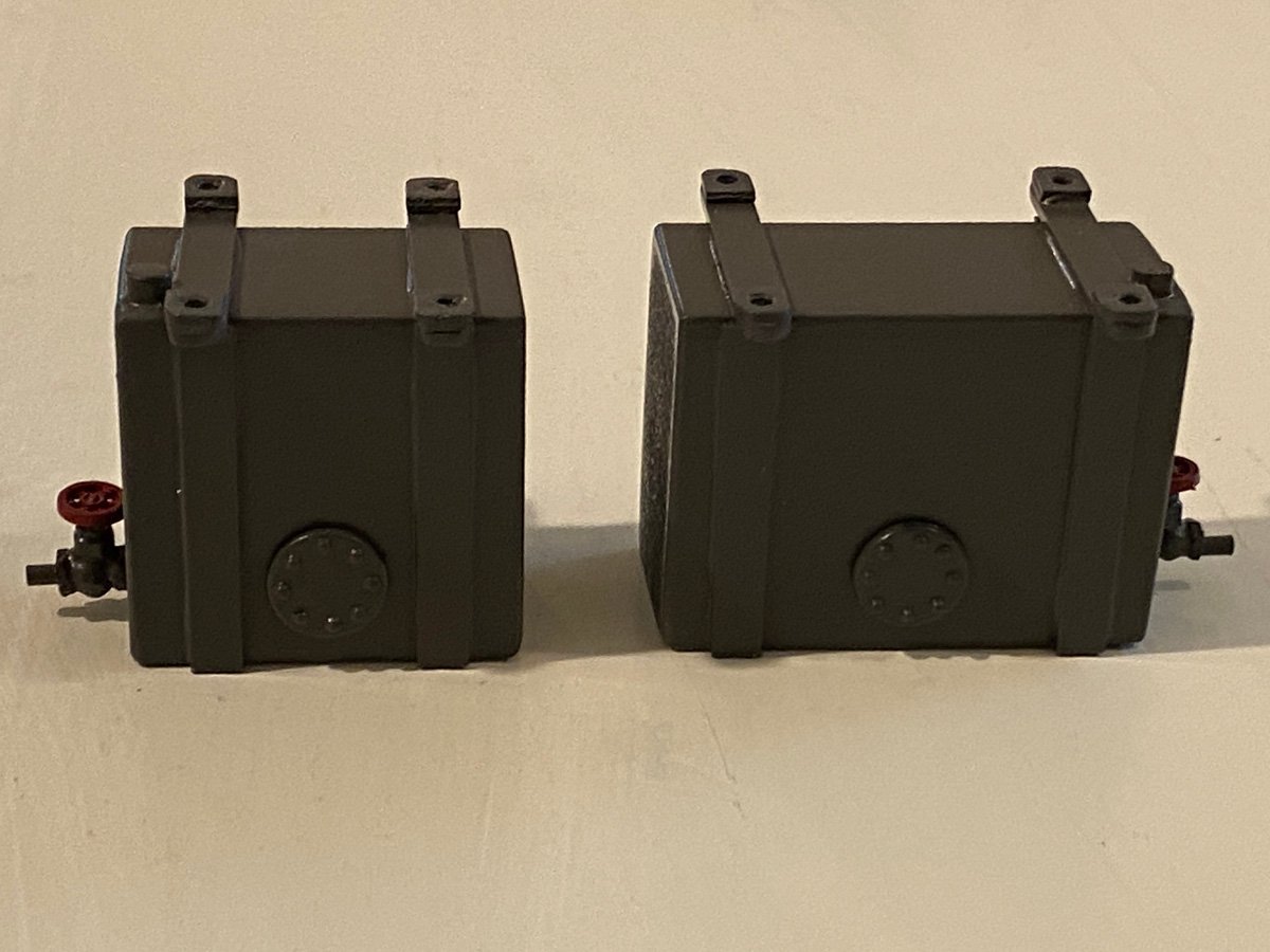
- 50 replies
-
- 6
-
-
- Marie Felling
- tug
- (and 3 more)
-
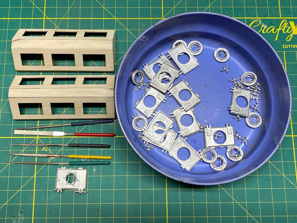
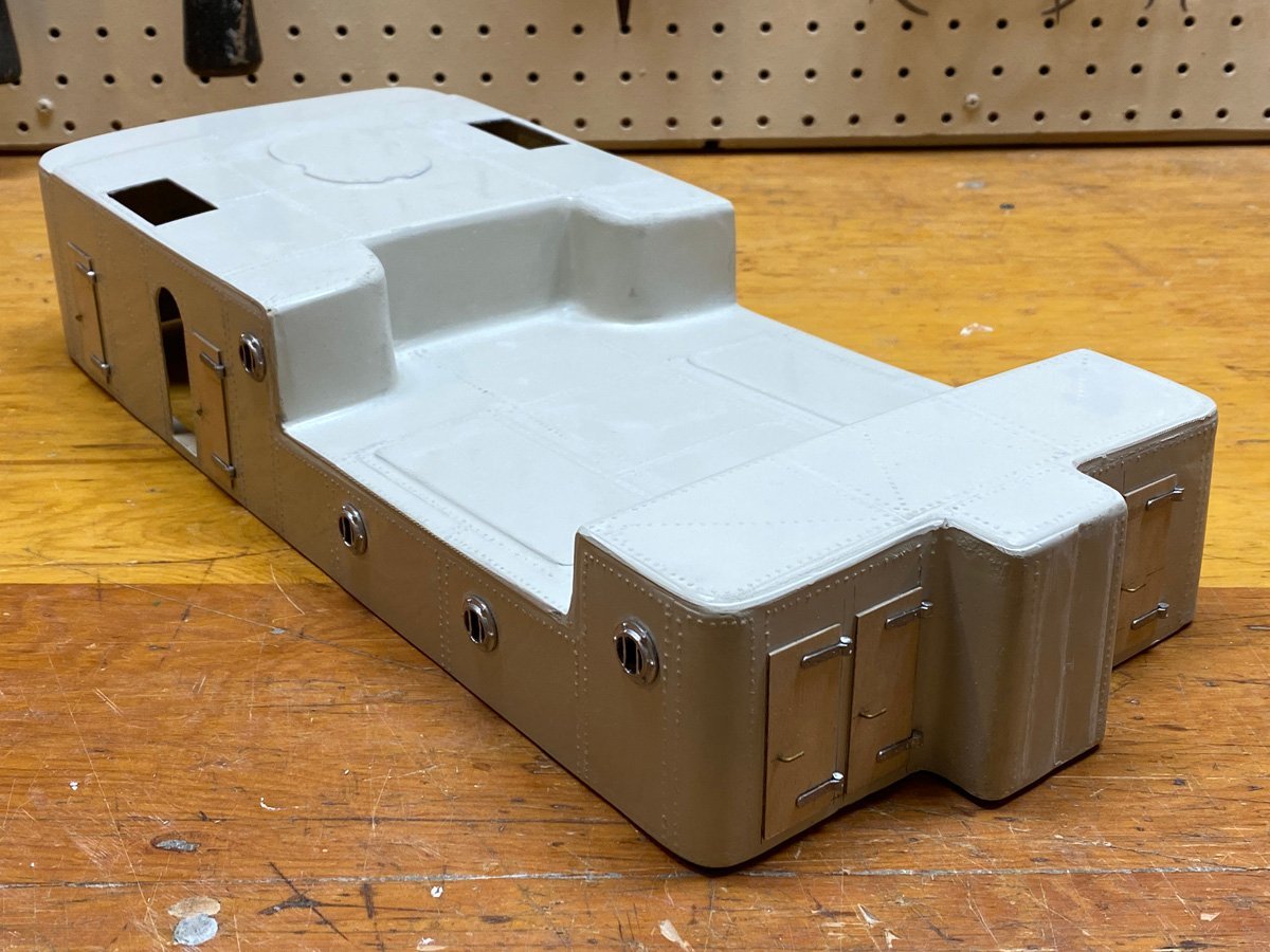
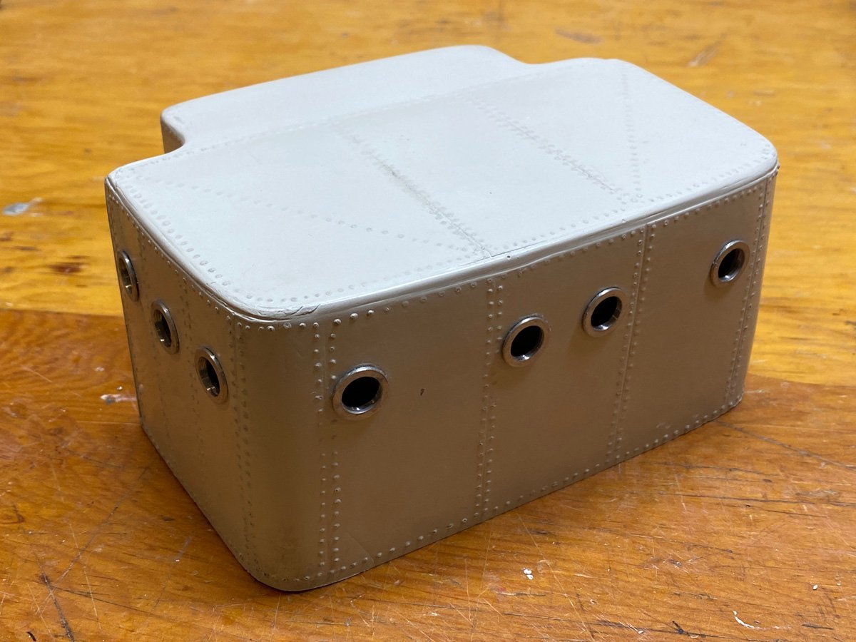
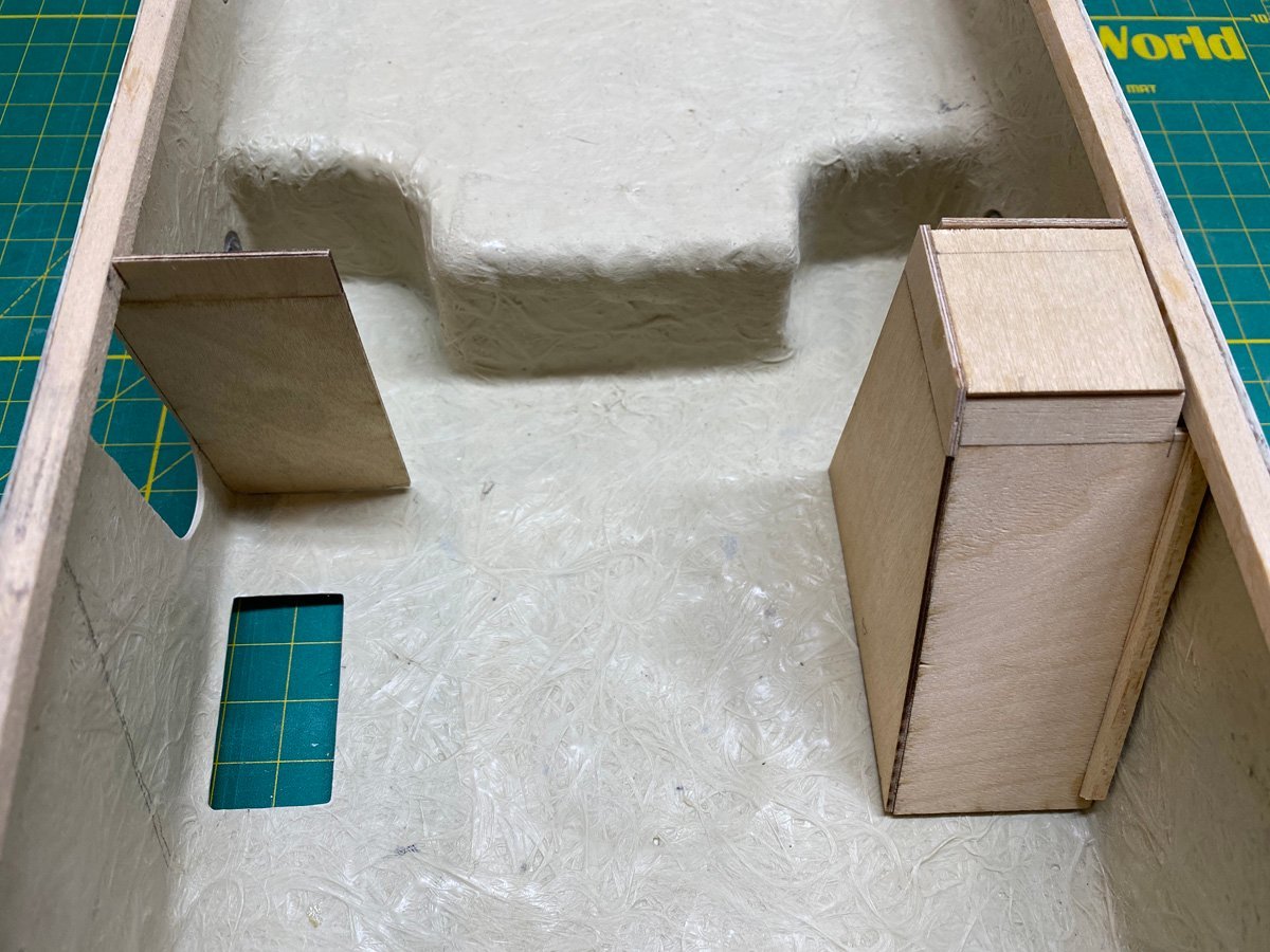
Cabin Details I worked on cabin details while waiting for paint to dry. The GRP cabins tend to bend inwards and required internal bracing. Then portholes, doors, and other details were attached. Portholes were bored with a step drill that basically grinds its way through the GRP with minimal splintering. The forward cabin has a lot of portholes, but there doesn't seem to be any doors! None of the 3 build logs listed above has mentioned that. Maybe the door is in the hidden space in the back? The rear cabin has a lot of portholes and SEVEN doors. It also has 2 stairwells that had to be cut out and framed in from the inside. Here's how I framed the stairwell. I will glue them in after painting. Here's how everything will fit together.

- 50 replies
-
- 6
-
-
- Marie Felling
- tug
- (and 3 more)
-
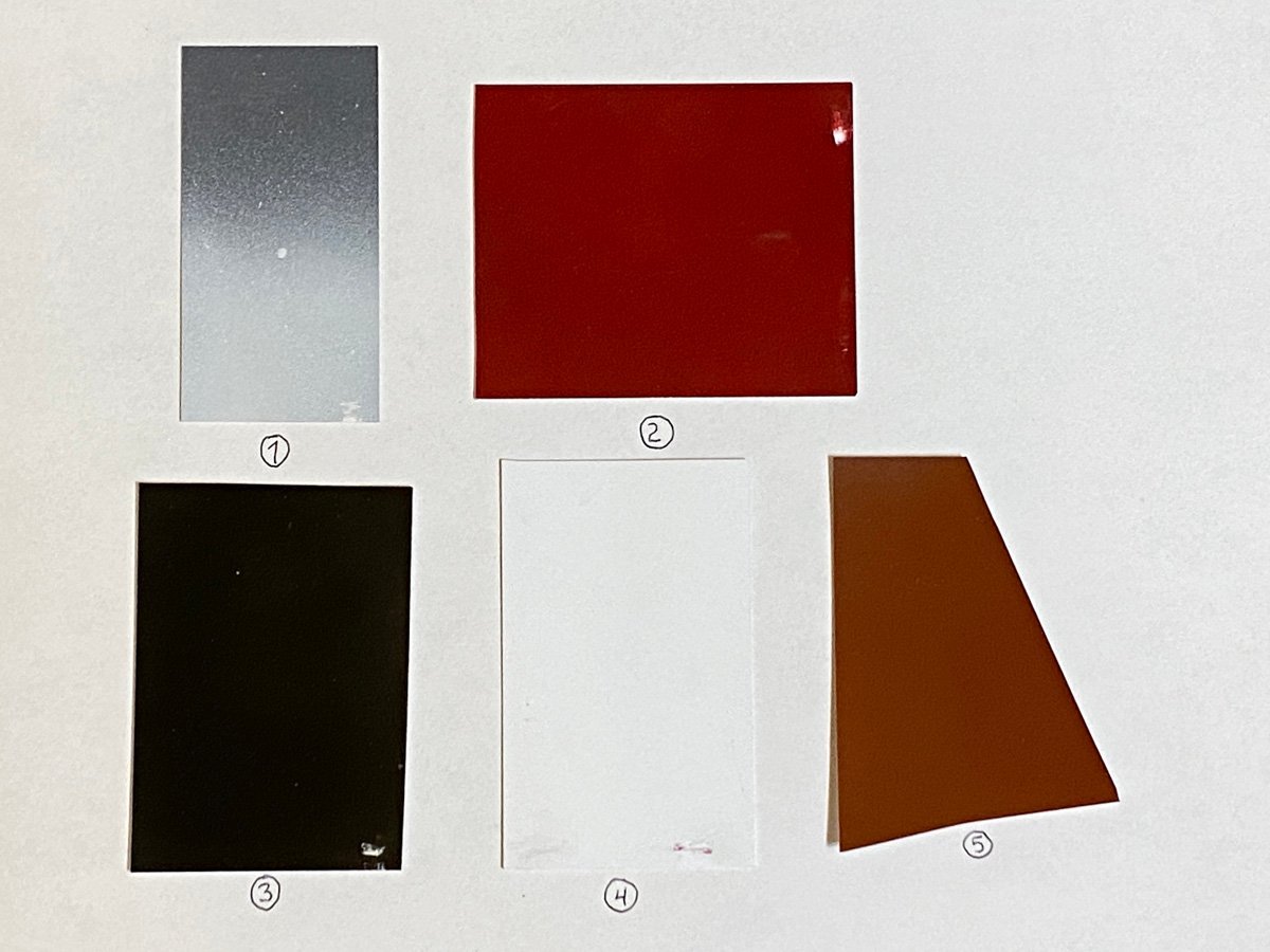
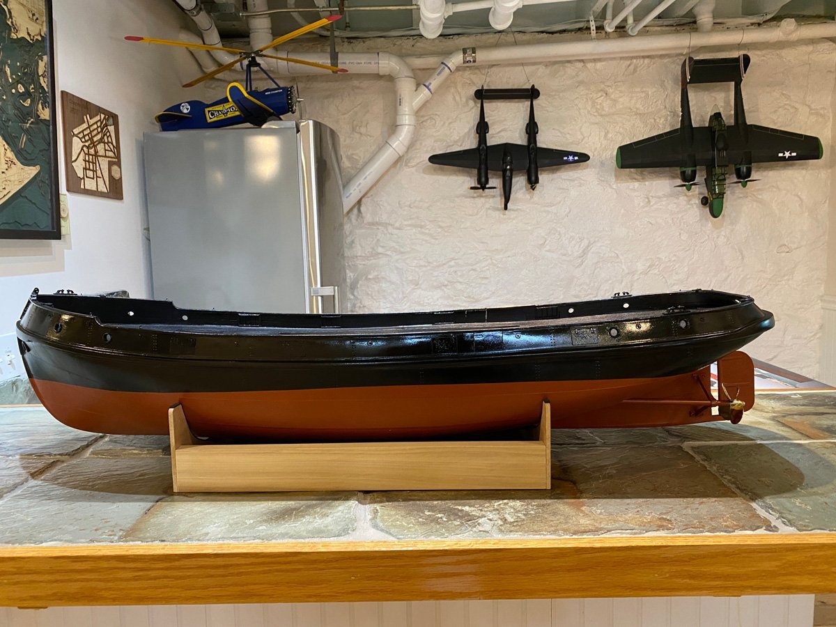
Paint Stripping, Experiments, and Repainting The Rustoleum primer did not stick to the GRP hull. This is what the hull looked like where it moved on my foam-covered stand. Soon after I made my last post I removed most of the primer using mineral spirits and coarse steel wool. The job only took a couple of hours wasn't as messy as I expected. I couldn't get everything and decided to leave the bulwarks primed. Here's the hull after stripping. In the meantime I tested several kinds of paint on styrene sheet. Rustoleum 2X gray primer, the primer that I had trouble with. Later I put Krylon white primer over it to make sure that they were compatible. They were. Rustoleum Colonial Red. I really like this color for anti-fouling paint on the bottoms of hulls, but I've already used it on three other models. Krylon Fusion gloss black. Krylon Colormaster white primer. Krylon Fusion Satin Brick, an alternative for the bottom of the hull. Next I tried to scratch each sample with a fingernail and then a hobby knife. They were all VERY difficult to scratch. So my original problem was the GRP. I still had two GRP superstructure components that had not been cleaned or painted. I cleaned one very carefully with Dawn and then TSP, then sprayed one face of each component with Rustoleum primer. The next day BOTH components scratched easily; so the problem was not lack of cleaning - Rustoleum simply does not stick to the GRP. I stripped both of those components. I re-primed the hull with Krylon Fusion gray primer. This is my high-tech spray booth, AKA garage. I painted the lower hull with 3 coats of Krylon Fusion Satin Brick, masked the water line with Tamiya masking tape, and painted the upper hull with Krylon Fusion gloss black. Everything came out perfectly and does not scratch. Here's the hull on the stand. You can see some of my other interests in the background. I still love this view. Now time to clean up the garage.
- 50 replies
-
- 8
-
-
- Marie Felling
- tug
- (and 3 more)
-
TBlack - Thank you for remembering the names of the margin plank and the nibbing. Once you figure them out they are actually easier to cut and fit than long, narrow curved pieces. BobG - I've already started removing the primer. After I brush on a little paint thinner and wait 5 minutes it comes off fairly painlessly. I'm still not sure what to use next. Thanks for letting me know about the link for the Anteo. It should be fixed. Ian - No, I didn't know to wash the hull. I do now.
- 50 replies
-
- 4
-
-
- Marie Felling
- tug
- (and 3 more)
-
Help - Primer Not Sticking! Yesterday I sprayed the hull with Rustoleum 2x Ultracover flat gray primer. After several hours I moved the hull to its cradle for some touch up work, and soon noticed that the primer was scraping off. I let it sit all night but it still scrapes off easily with a fingernail. The Rustoleum can says that it does not work well on polyethelene, but I think GRP is usually a polyester resin. The can also says that best adhesion on plastics is achieved in 5-7 days. Should I try to remove the paint with mineral spirits, or should I wait 5-7 days and hope for the best? Rod
- 50 replies
-
- 5
-

-
-
- Marie Felling
- tug
- (and 3 more)
-
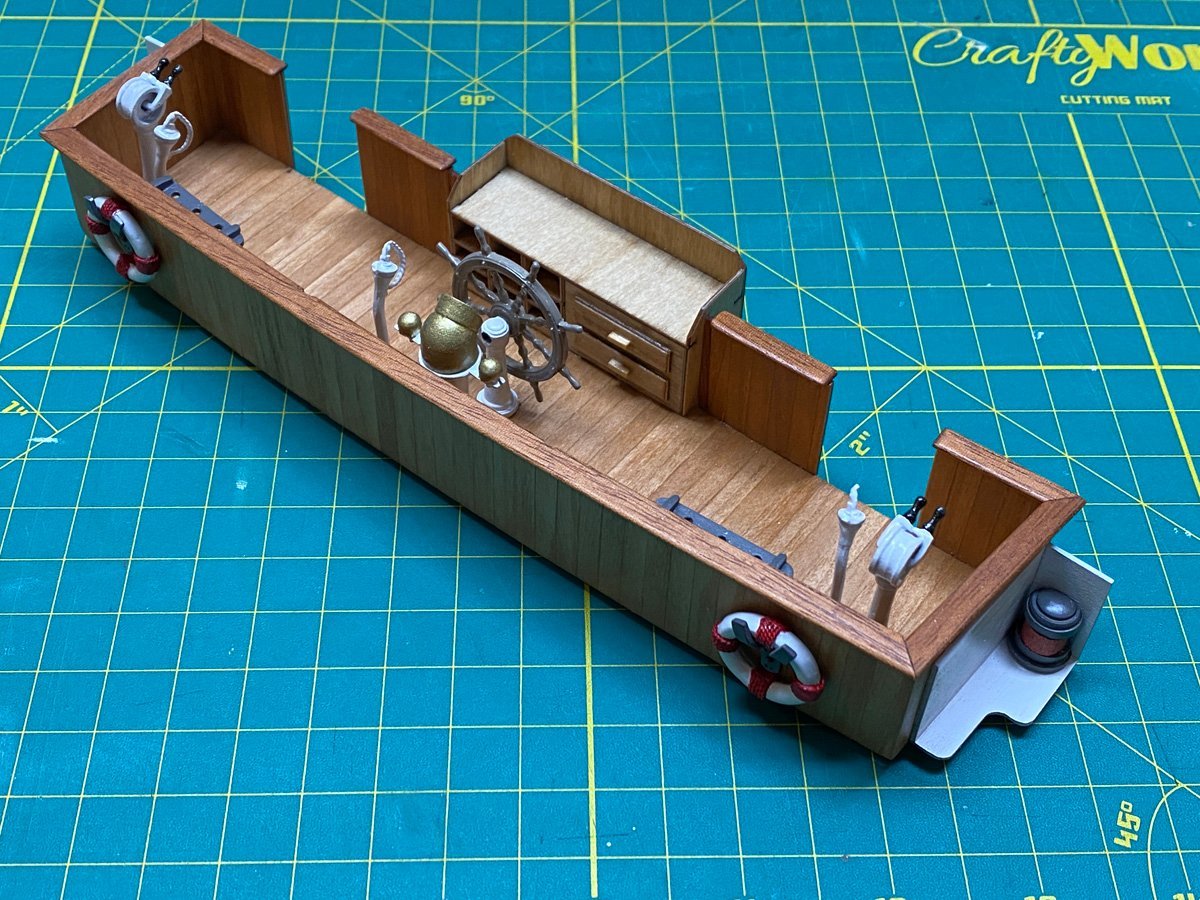
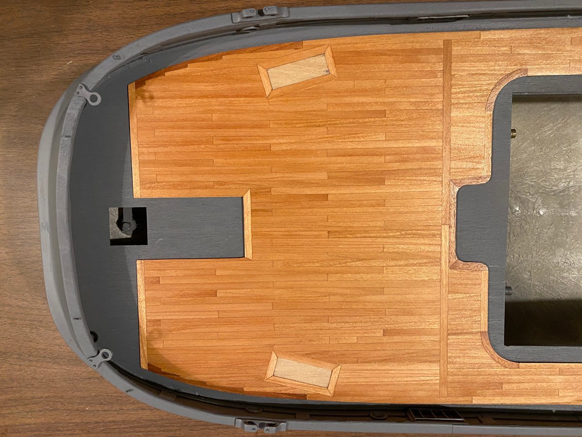
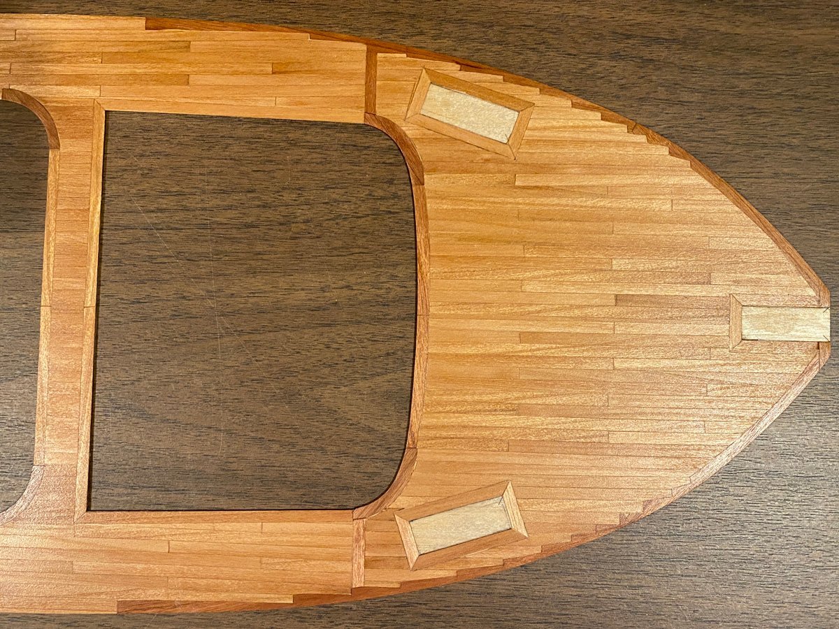
Deck Planking, 87 hours I bought some cherry strips 0.5 x 5 x 1000 mm from agesofsail.com and used them to plank over the plywood deck overlay supplied with the kit. I used some cherry veneer for the curved pieces and they came out slightly darker. I filled the entire surface with Timbermate wood filler in white oak, sanded, stained with Watco natural, and applied several coats of Minwax Polycrylic clear semi gloss. The entire job took about 20 hours over 3 days, and I couldn't be happier with the outcome. I love the way that the planks are stepped into the curved edges. There's a term for that but I don't remember what it is. Does anyone know?
- 50 replies
-
- 10
-
-
- Marie Felling
- tug
- (and 3 more)
-
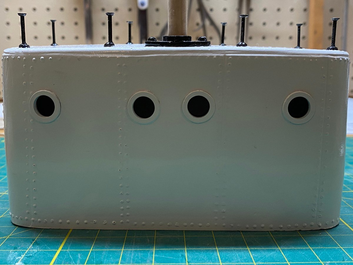
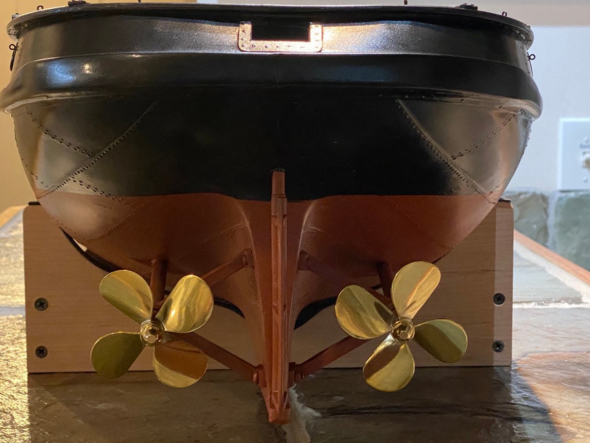
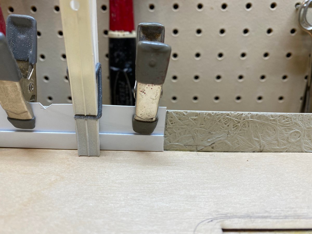
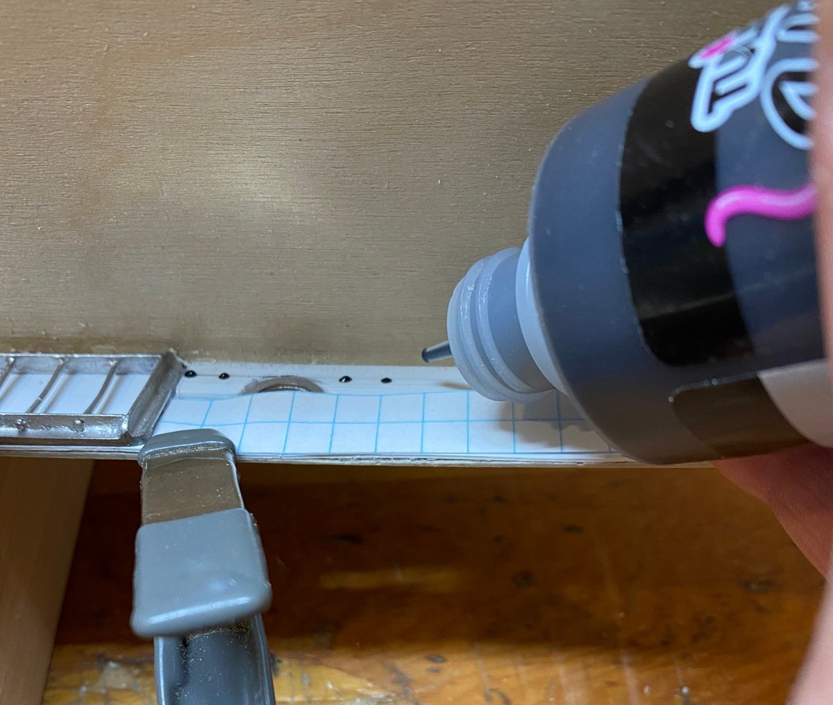
Bulwarks and Hull Details, 48 hours The inside of the GRP hull is rough. The instructions suggest smoothing it with some random resin., but I used Rmay's suggestion on rcgroups.com (see link above) and lined the bulwarks with 0.5 mm styrene with a 1 mm strip along the deck. I had to leave room for the side ports. The rivets are made with Tulip fabric paint, another idea from Rmay on rcgroups.com. The container has a thin nozzle that is perfect for dabbing rivets. The paint is very thick and drys quickly with a distinct, raised feel. They look a little sloppy but should be fine when painted. Finally, my 65 mm Raboesch propellers came today. They are just outstanding and certainly make the business end of this tug look nice.
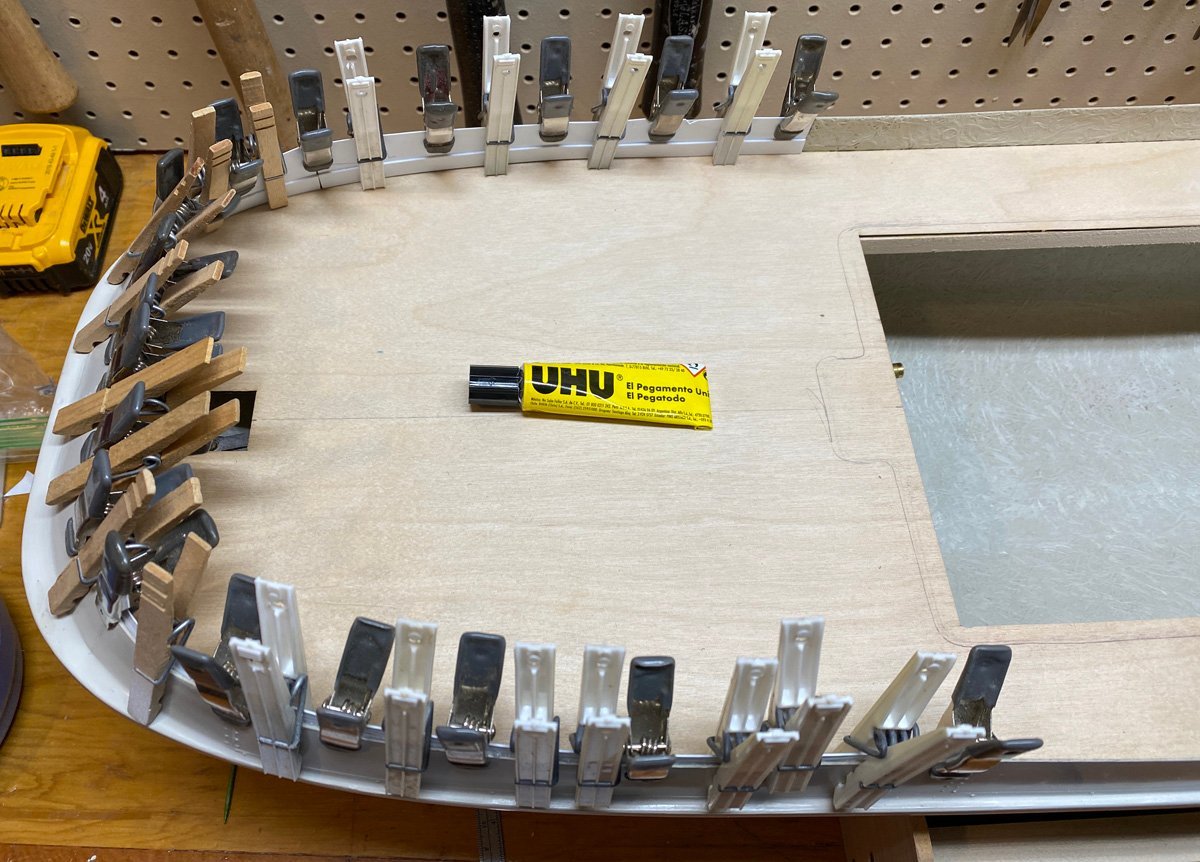
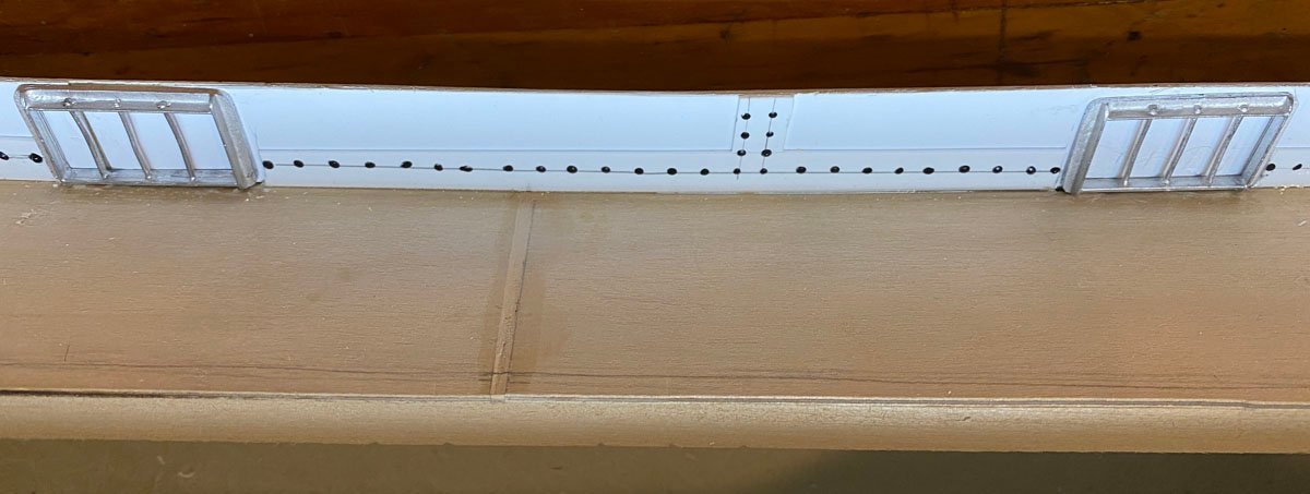
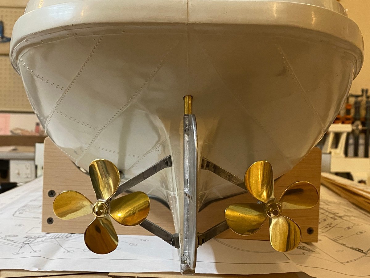
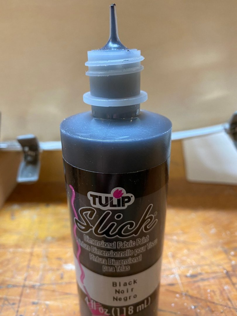
- 50 replies
-
- 12
-
-
- Marie Felling
- tug
- (and 3 more)
-
I am happy to know that there are some Caldercraft fans out there. I love cutting wood so I am having some doubts about building this kit, but I also think that it will turn into a handsome model.
- 50 replies
-
- 5
-
-
- Marie Felling
- tug
- (and 3 more)
-
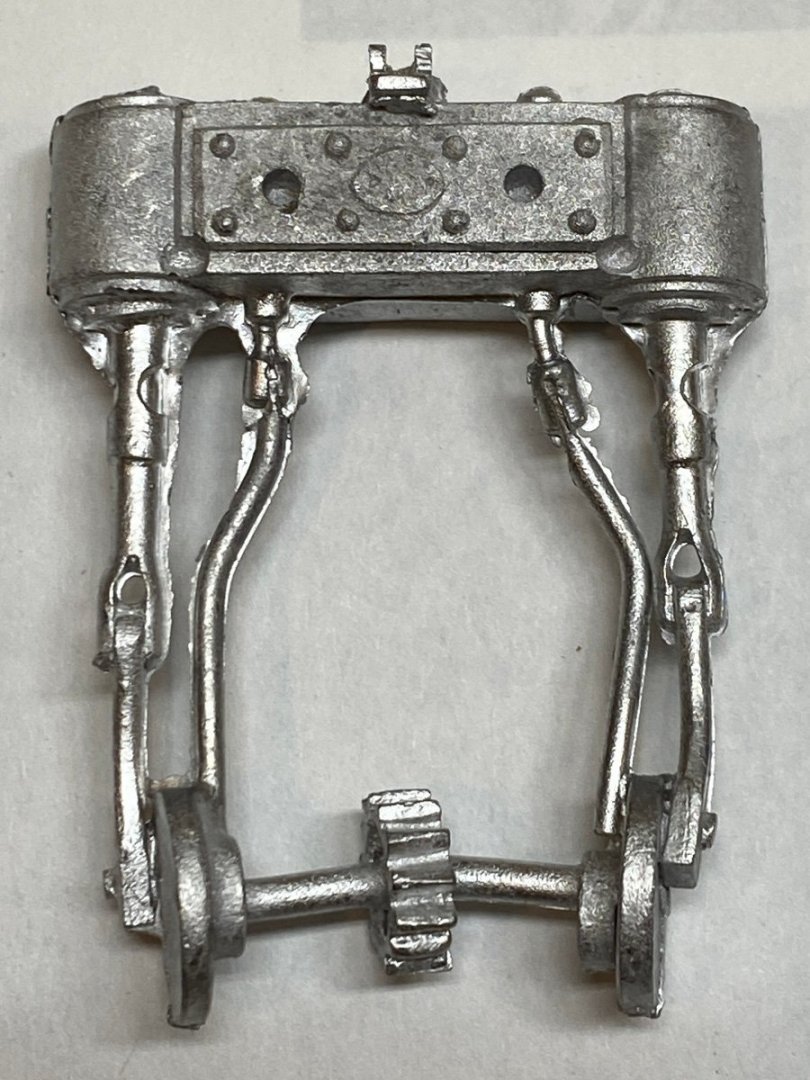
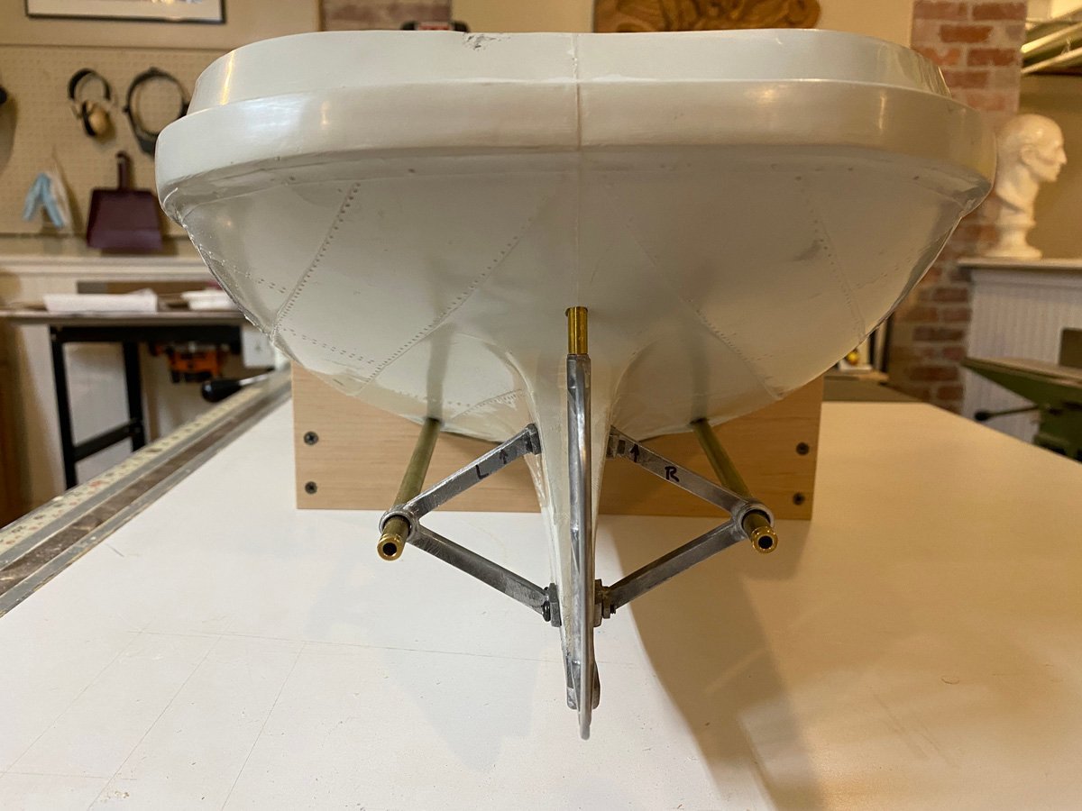
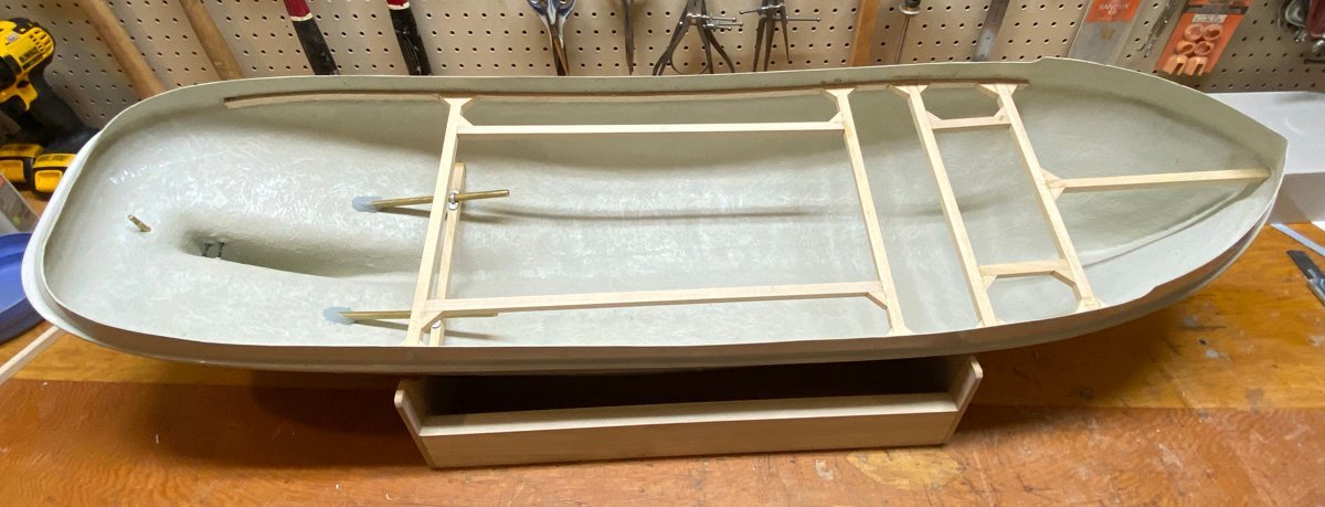
Prop Tubes Installed, Interior Framing Completed 1 month, 28 hours Step 1 - Install the A-frames, rudder support, and prop tubes. The white metal parts required a lot of cleanup. The instructions are vague and the supplied bolts didn't fit. Thank goodness for those other build logs. Step 2 - Build some supports for the sub-deck. The instructions basically say to superglue the deck in place and seal the perimeter with resin. So far I have done everything the same way that the RC builders have done. I spent several hours yesterday building a cradle to hold the model while I work on it. I'll build a nicer stand for display. The model is too big to turn easily on my bench, but the cradle helps. Here the sub-deck, printed deck, and superstructure are installed temporarily to check the fit.
- 50 replies
-
- 8
-
-
- Marie Felling
- tug
- (and 3 more)
-
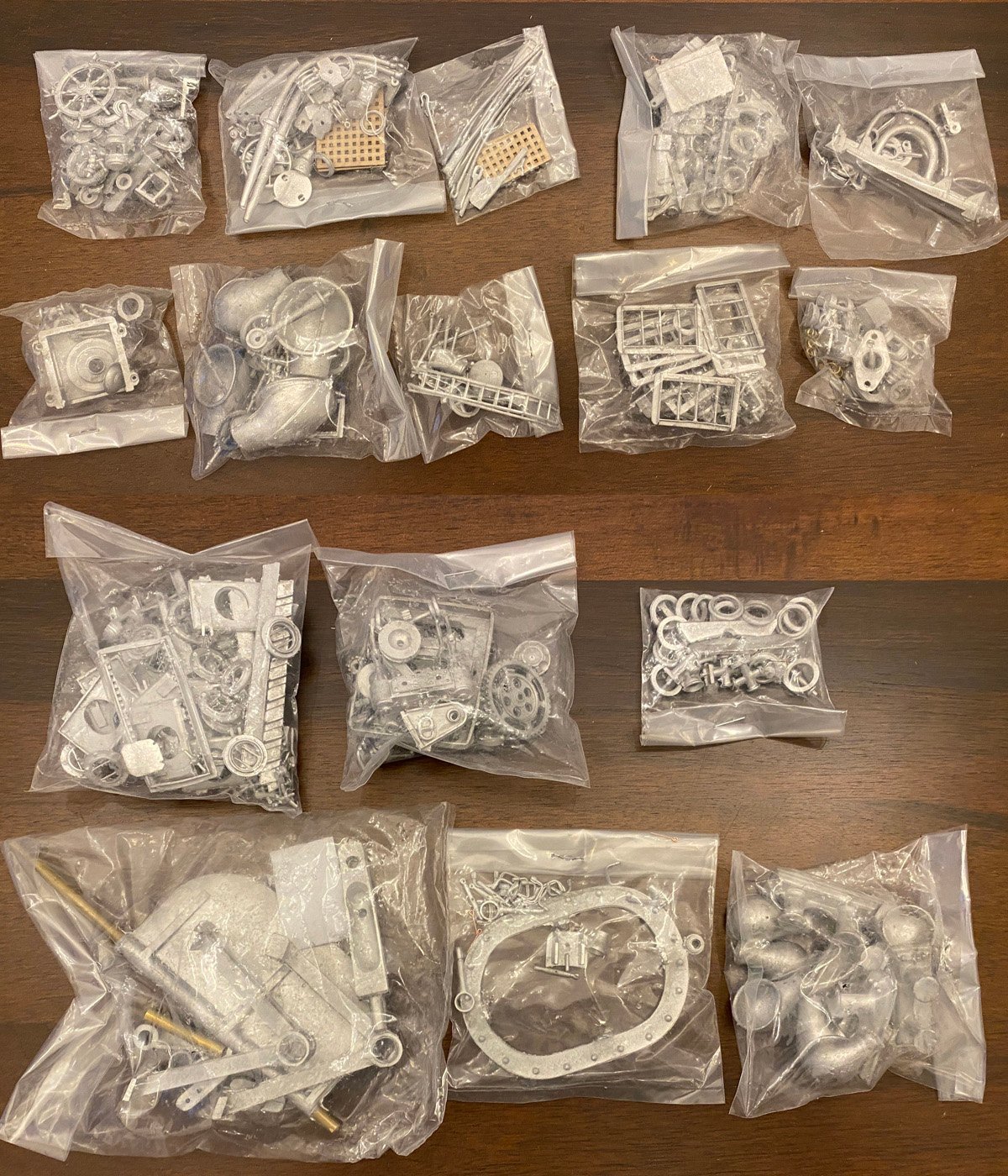
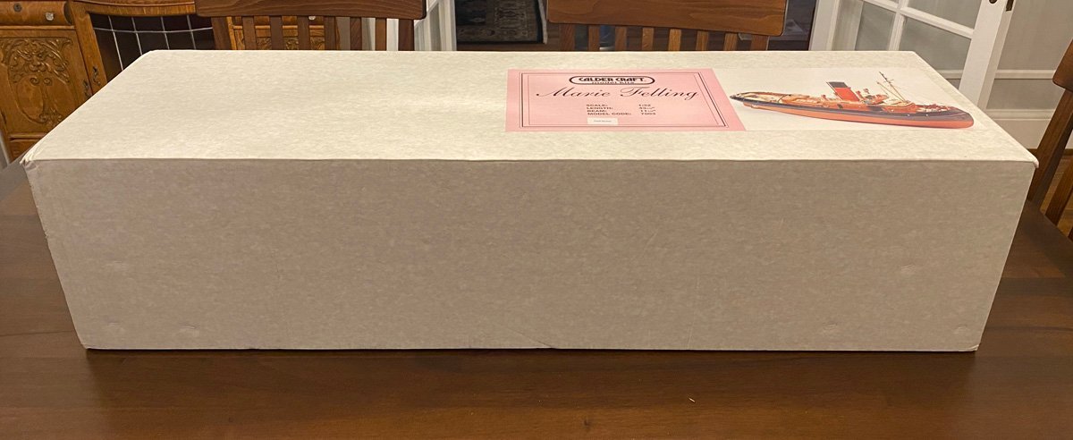
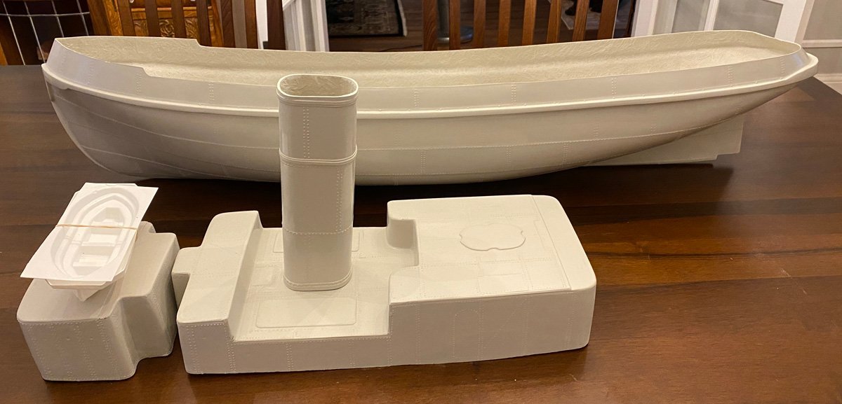
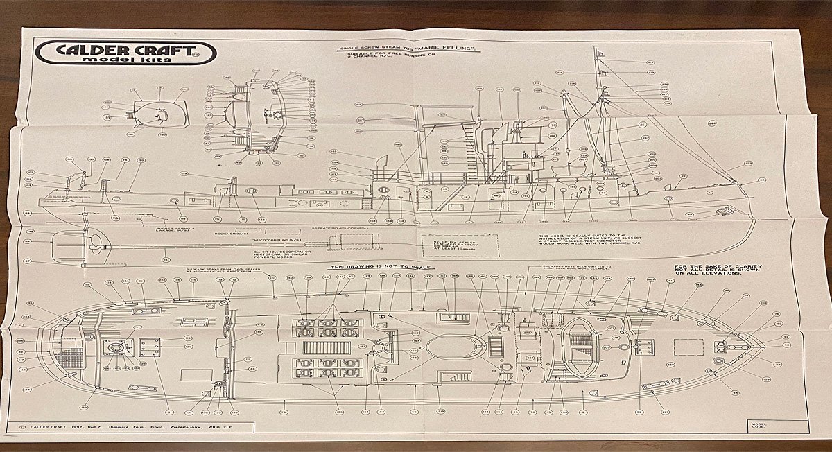
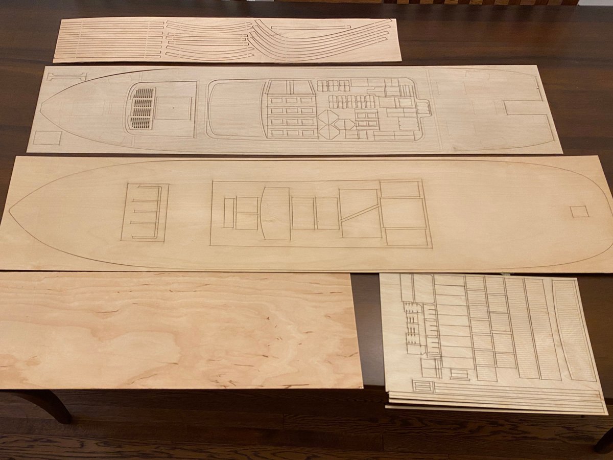
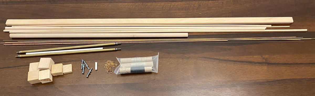
What's in the Box The BIG model comes in a BIG box, almost as big as the ARF airplane models for sale at the hobby store. Most of the box is for the GRP hull and superstructure. There is one page of plans at the wrong scale, and a slim instruction manual with only a few illustrations. All of the build logs on rcgroups.com agree that the plans are poor and the instructions are terrible. I've already consulted those other build logs several times to see how to build things. More on that later. There are several sheets of high-quality laser-cut ply. The deck planking is printed nicely but I plan to plank the deck. There is a quantity of dowels, strip wood, and wire and tubing. The kit includes two good prop shafts but no props. I just ordered those. A single screw version of the kit is also available. Finally, the kit contains about 600 well-made white metal parts, package for each major assembly. I'm not too fond of working with Glass Reinforced Plastic or of cleaning up white metal castings. What have I gotten myself into?


- 50 replies
-
- 8
-
-
- Marie Felling
- tug
- (and 3 more)
-
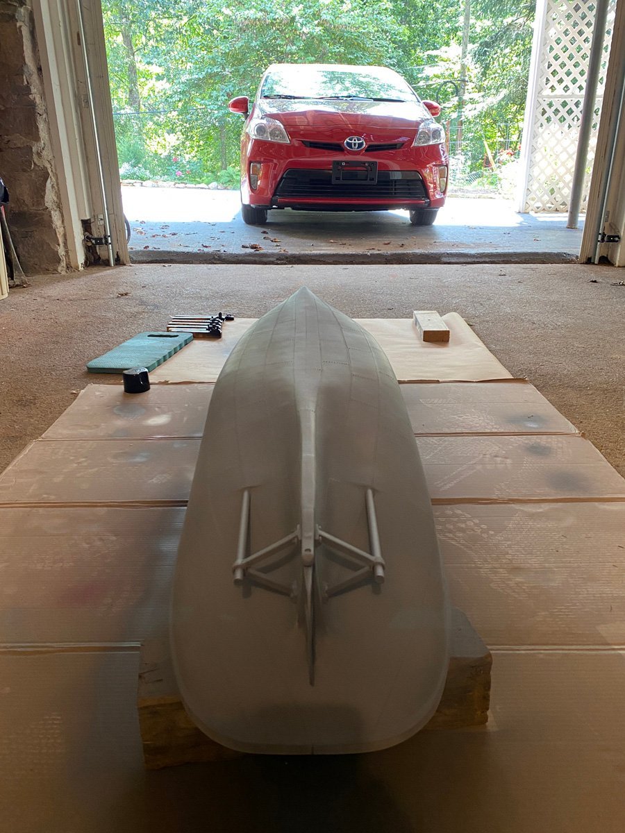
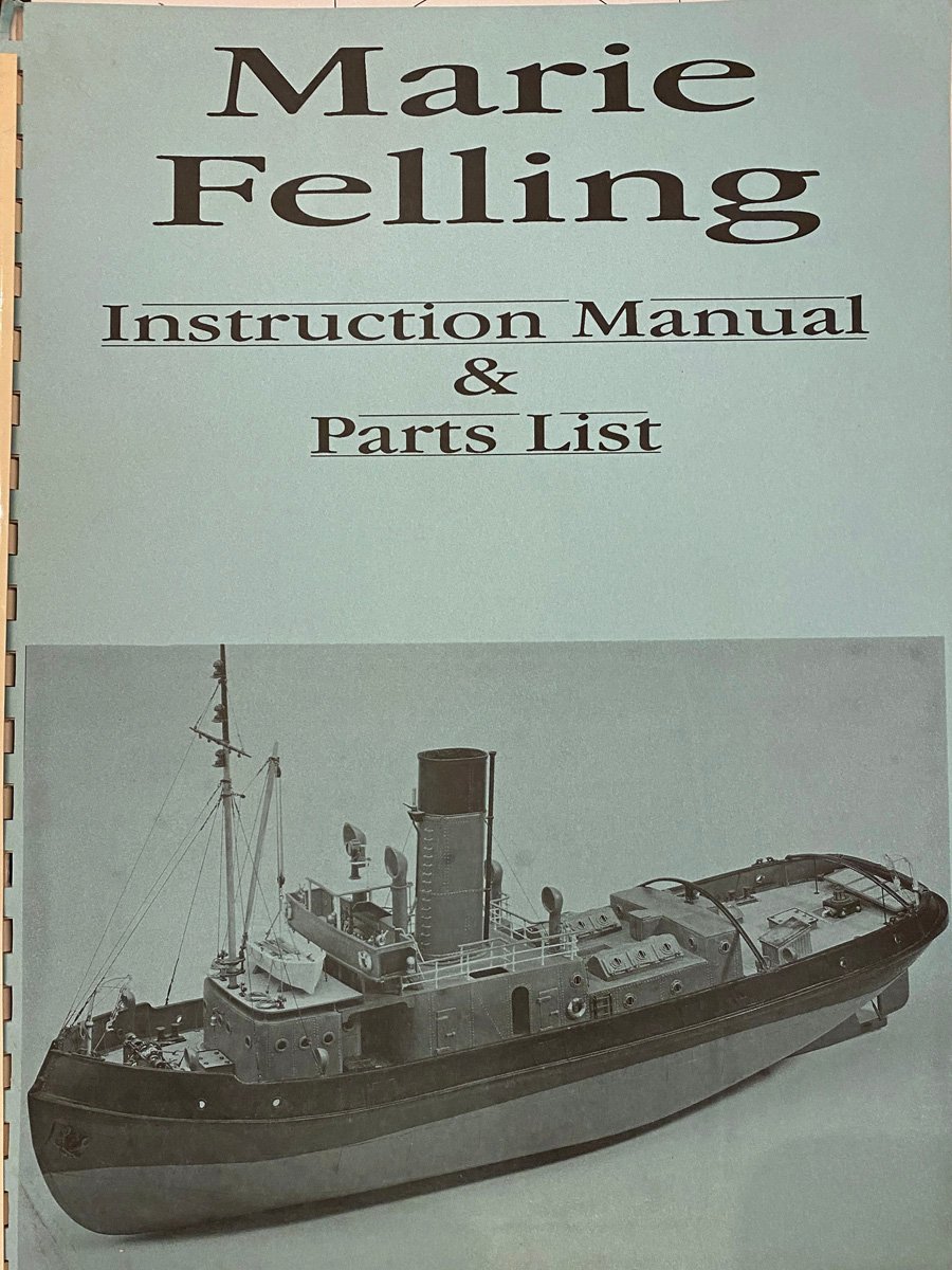
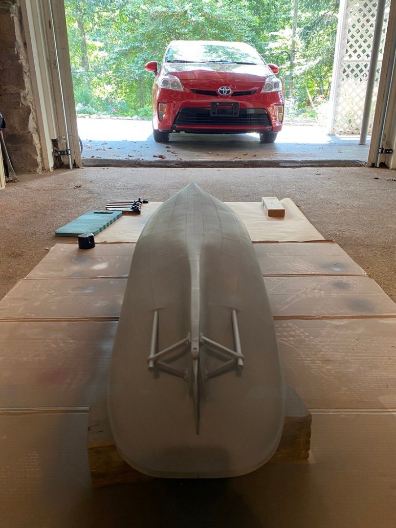
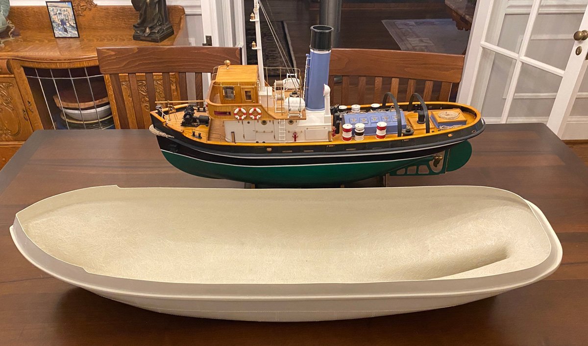
I've made several ship models in the last 10 years. My best work was on the HM Bark Endeavour by Caldercraft, but the model that gets the most compliments is my Anteo Harbour tug. I've been wanting to build another tug for a while and settled on the Marie Felling by Caldercraft. They offer a couple of other tug kits but they are nearly impossible to find at the moment, so I settled on the Marie Felling. This is a BIG model, 43.5" long. It has a Glass Reinforced Plastic (GRP) hull and superstructure and is clearly made for RC. I just build for the fun of building, and will build this as a static model. Here's a photo of the GRP hull next to my Anteo. MSW has no build logs for Caldercraft tugs or the like, so I hope that this will give the readers some information about this. There are three good build logs on https://www.rcgroups.com, all of RC equipped models of course. Here are links if you're interested. Marie Felling by Longbike Marie Felling by Rmay Marie Felling by Kaskazi
- 50 replies
-
- 8
-
-
- Marie Felling
- tug
- (and 3 more)
-
I'm afraid that I don't know anything about powered boats. My model is strictly for display. Somewhere else on MSW I posted that some of the planking on the Anteo cracked with changes in humidity. A little disappointing for a display model, but you would probably have use glass fiber over an operating model. Rod
-
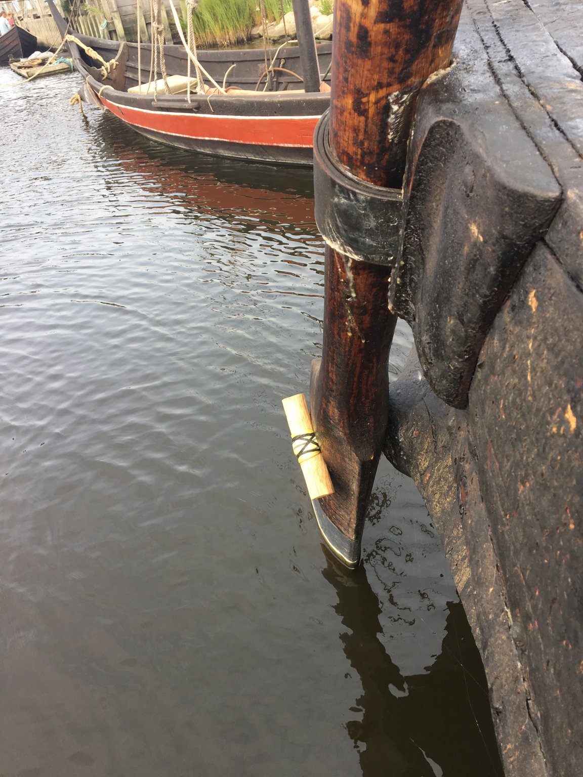
Matt, Thank you for the information about attaching the rudder. After a lot of searching online I found this photo of the rudder for the Ottar Viking ship replica in Roskilde, Denmark. It looks like you got the attachment right. I just attached my rudder and ran into the same problem that you did - once the deck is planked there is no way to attach the rudder pivot rope inside. I simply folded the rope in half, pushed it into the pivot button, and put a small nail through the button from the side to catch the rope. The third small line on your rudder would be for raising the rudder in shallow water or when beaching the ship. After removing the upper rope (leather band on the Ottar) and steering handle the rudder could be pivoted upwards. You made the right choice with the Amati kit. The Billings kit is 1:25 scale and is just too big. It's going to take up a lot of space in my house, and it doesn't have that much interesting detail for such a large model. Thanks again for the help. Rod

-
Hi Matt, Congratulations on a beautiful model! Did you really complete it in less than 2 months, or was that just when you posted to your log? I am building the Billings Osberg kit and your log has been a big help to me. I have really been puzzling over the attachment of the rudder. Everything I've seen shows a leather strap around the top, which would allow the rudder to turn, but a pin through the blade and hull which would prevent it from turning. You used a rope between the blade and hull, which makes sense. Did the Amati instructions show that or did you find another reference? Many thanks. Rod
-
Jack, I don't know if you're still out there, but I just wanted to thank you for your awesome build log on the Billings Oseberg Viking Ship. I am just starting on the same, and have gone through your log completely and taken notes on everything that I will need to address. You said that you built your model for The Admiral. My wife writes young adult fantasy novels (search for Cinda Chima on Amazon). Her next book is about Viking witches, so she definitely needs a Viking longboat. The book won't be out for a year so I have plenty of time. Thanks again for all the work that you put into your log, and congratulations on a beautiful model. Regards, Rod Chima
-
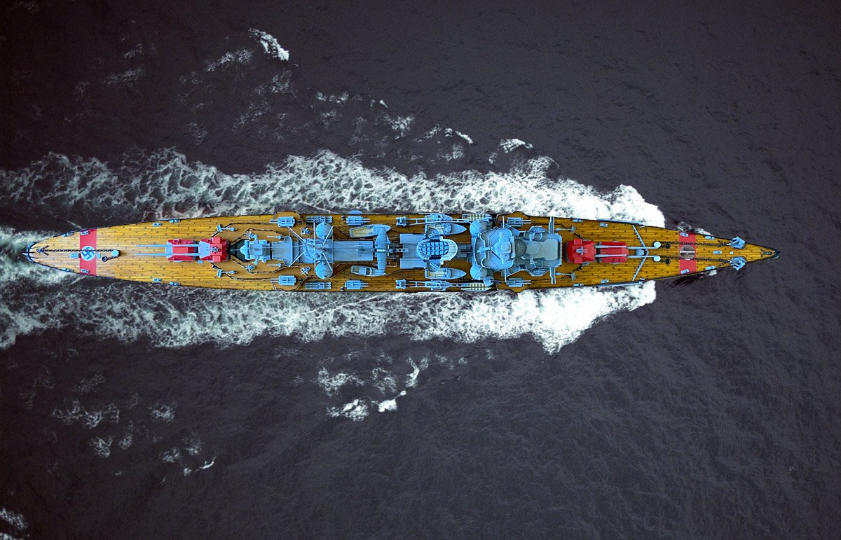
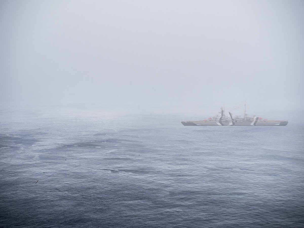
Fun with Photoshop Aerial view of the Prinz Eugen. Those red markings are just screaming to the Luftwaffe, "I'm German. Don't bomb me!" Dazzle camouflage in the fog. Which way is he going?
- 40 replies
-
- 5
-
-
- aeronaut
- kriegsmarine
- (and 2 more)