scrubbyj427
-
Posts
1,700 -
Joined
-
Last visited
Content Type
Profiles
Forums
Gallery
Events
Everything posted by scrubbyj427
-
 They are already pre boxed and ready to go! You could build without them I suppose. They are critical parts so you’d have to print them yourself.
 -
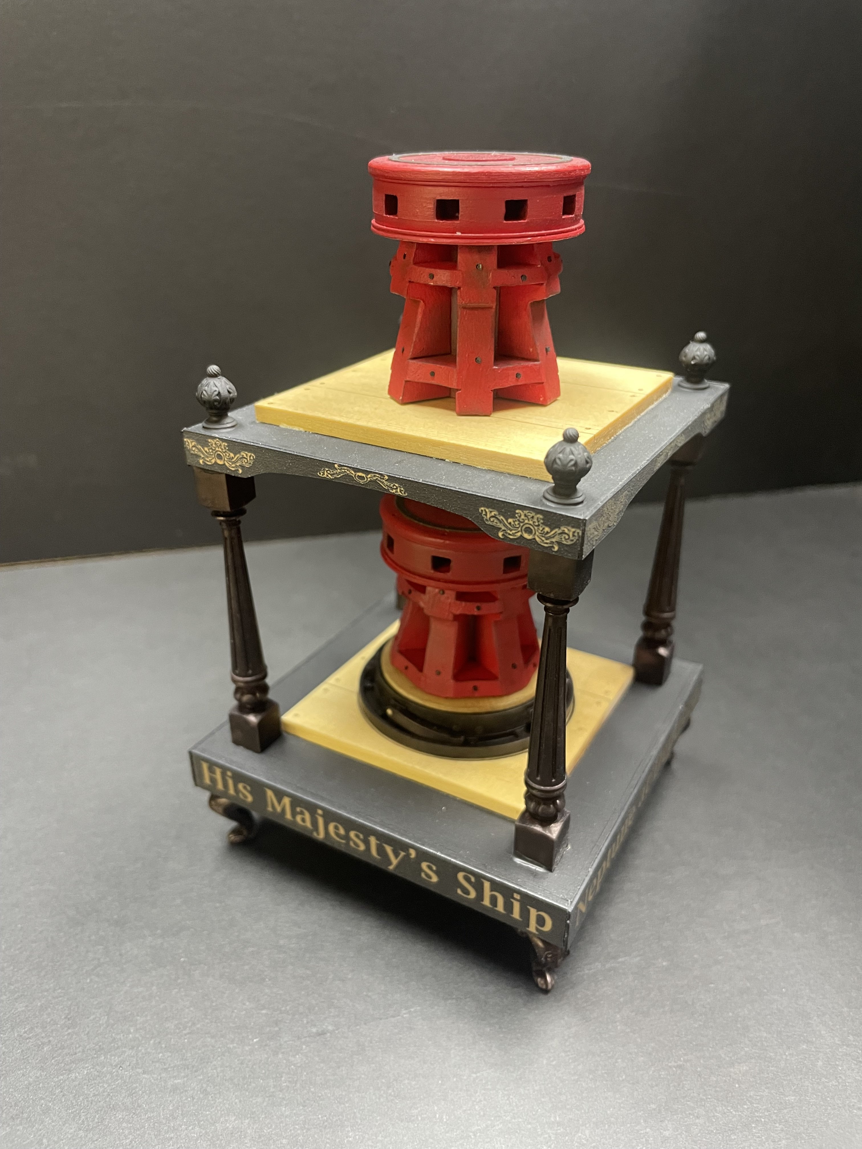
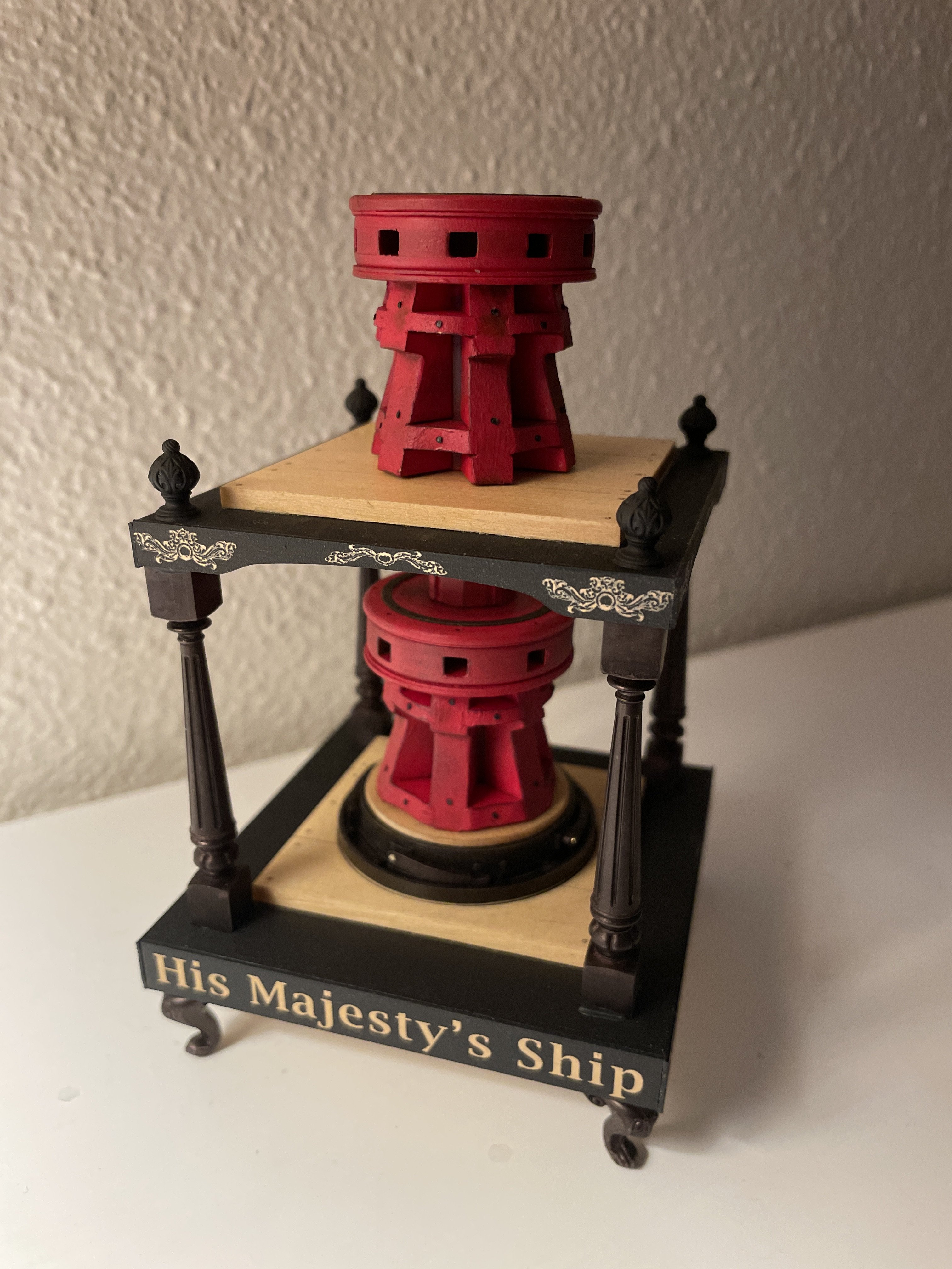
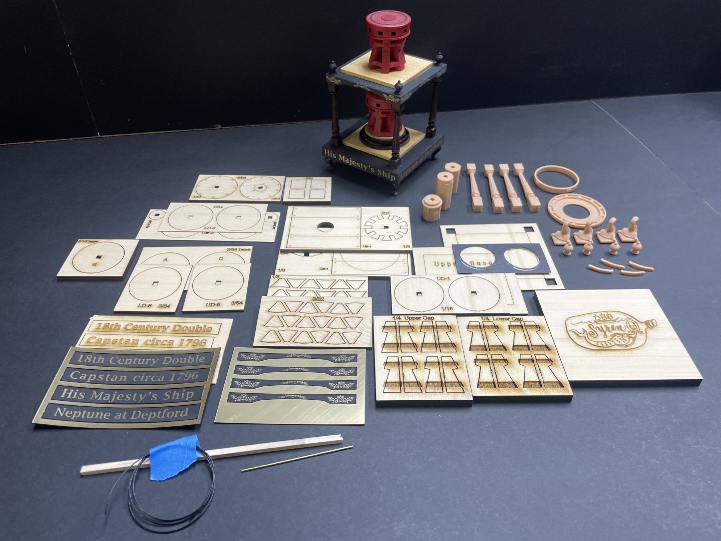
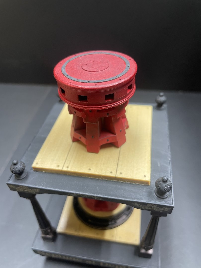
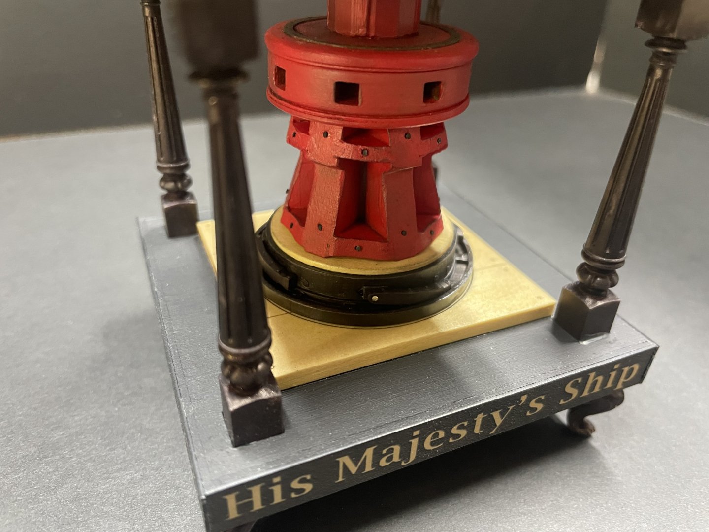
I just added a few capstan kits to my inventory and they are available now. https://portlandscaleshipco.com/product/hms-neptune-1796-capstan-model-kit/
-
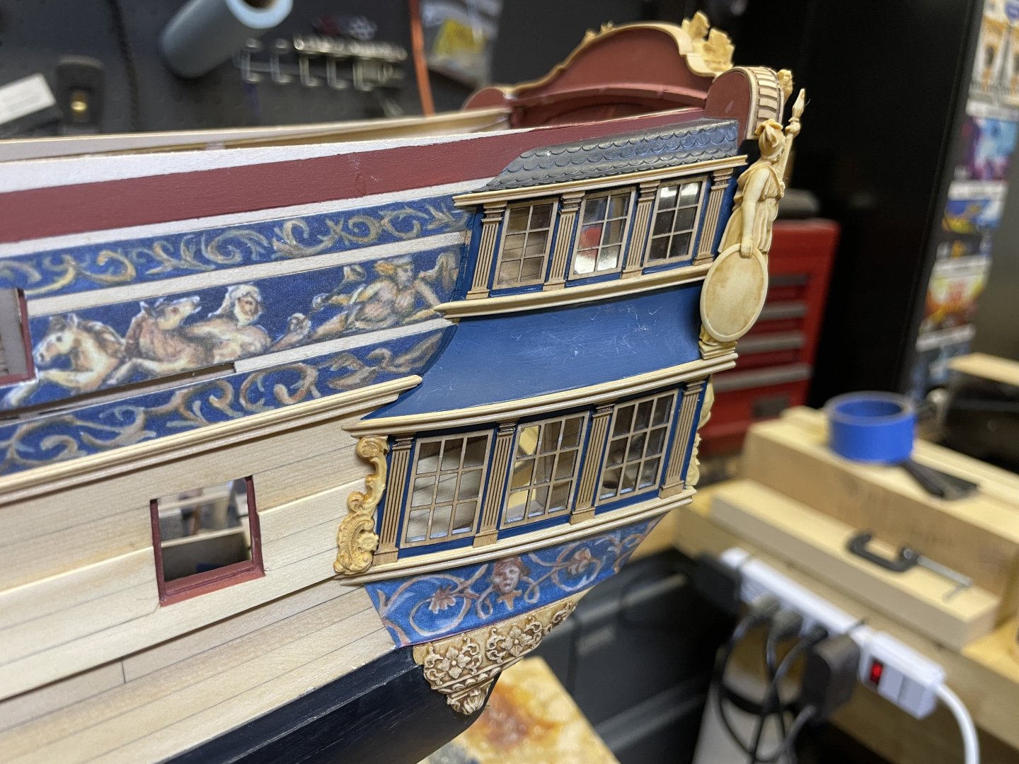
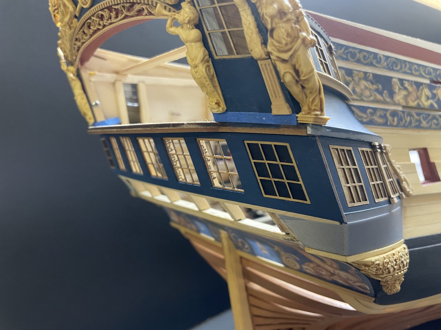
Almost finished with the QG on the port side. Hopefully it’s getting harder to tell they are printed at this point.

- 404 replies
-
- 21
-

-

-
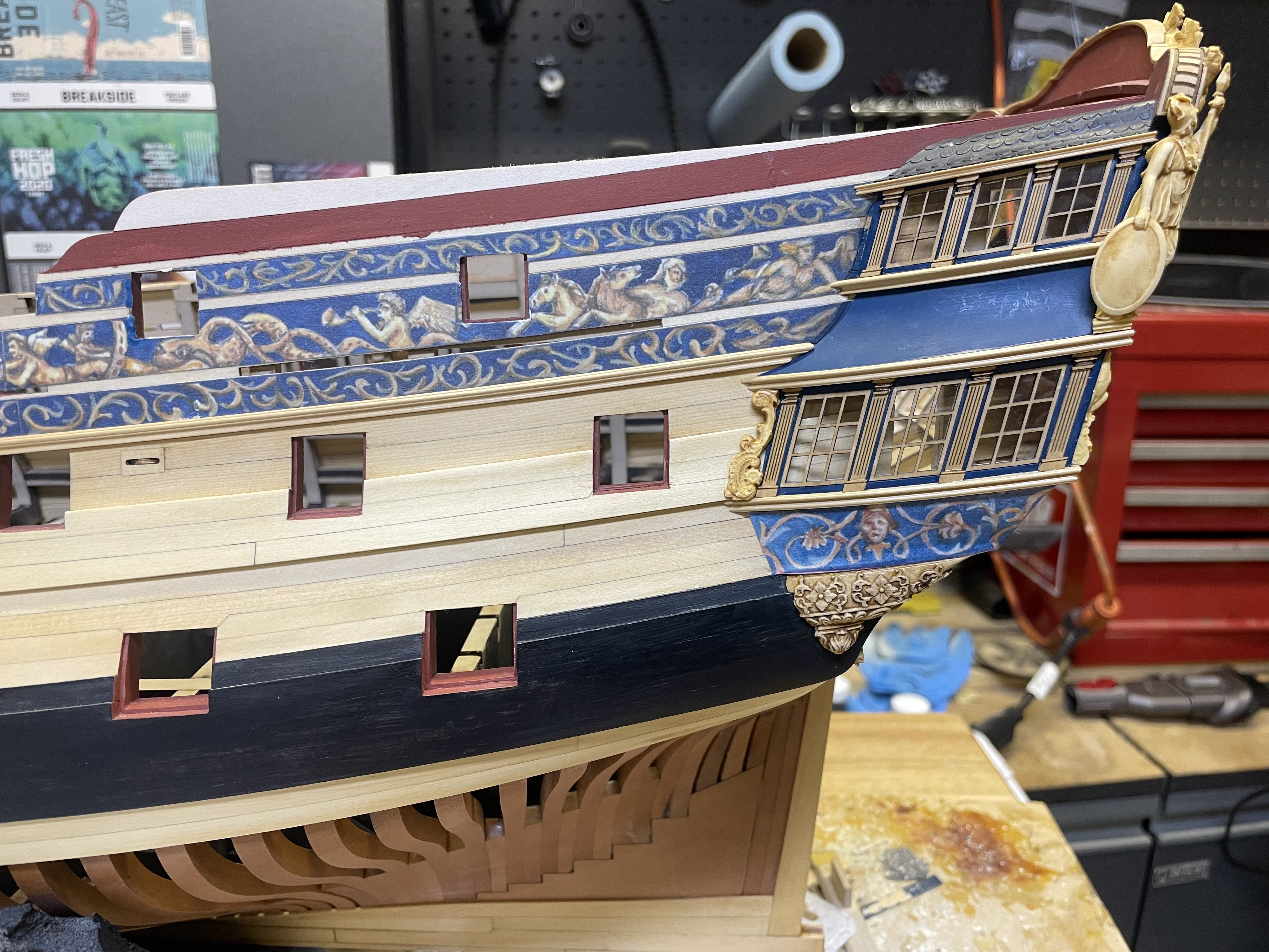
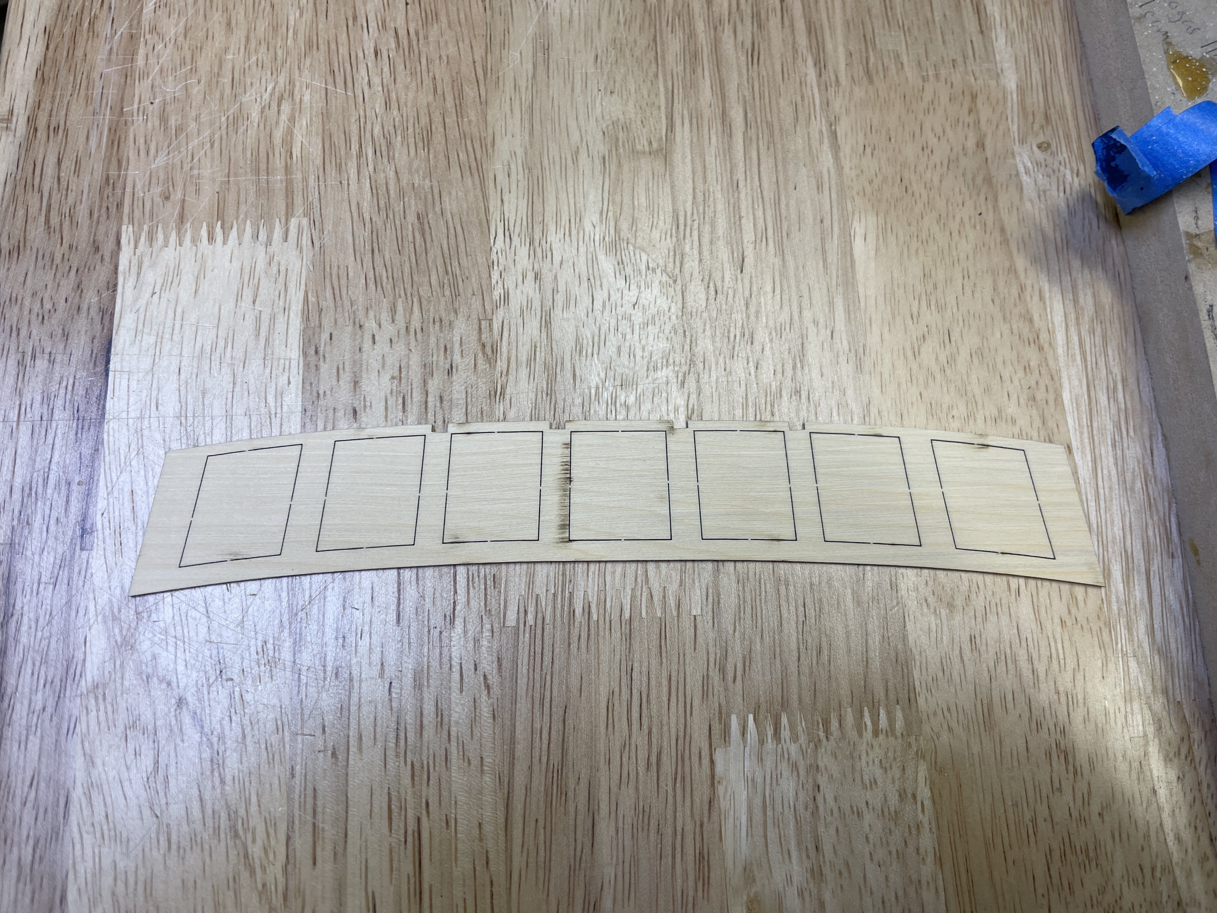
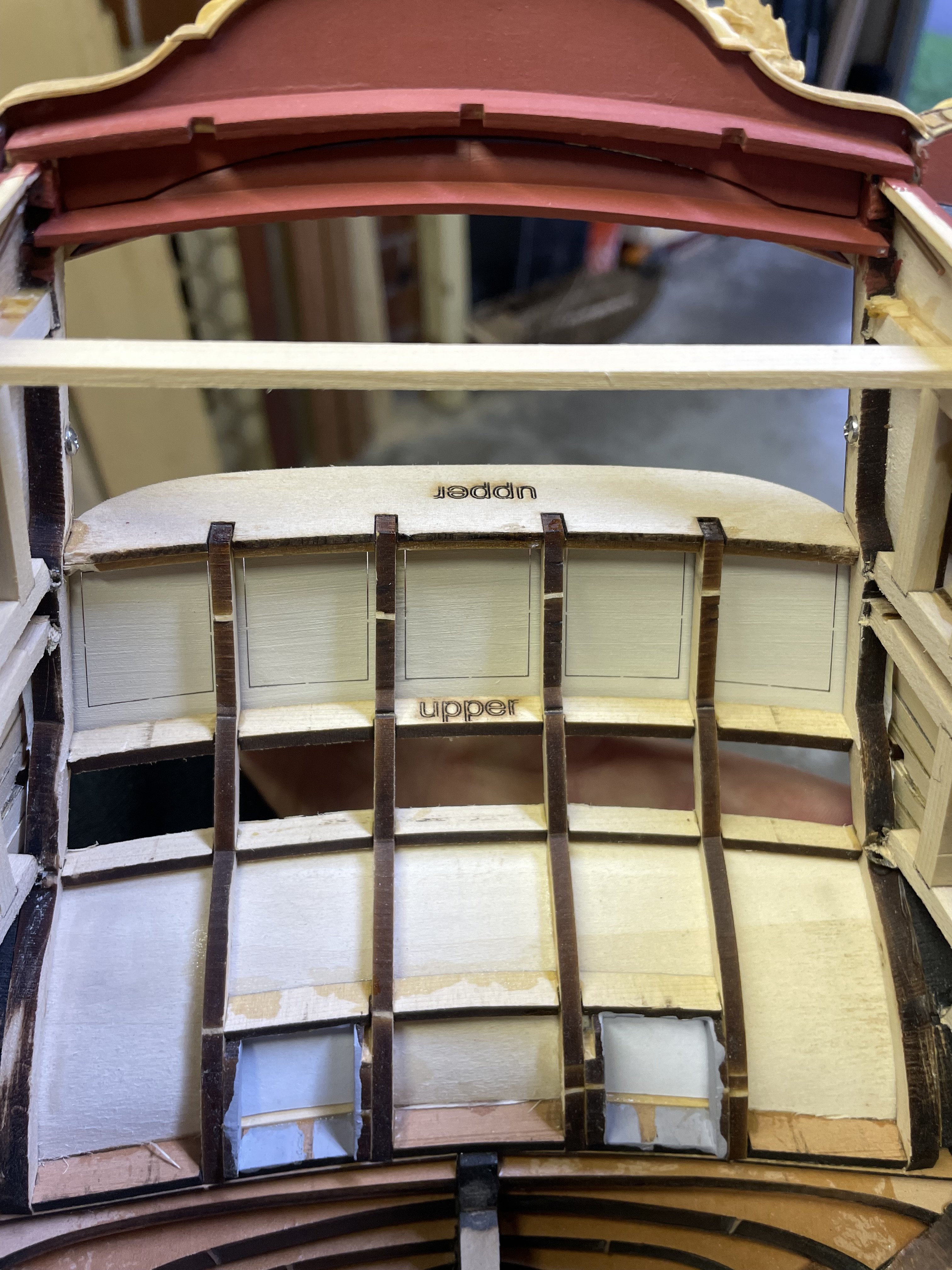
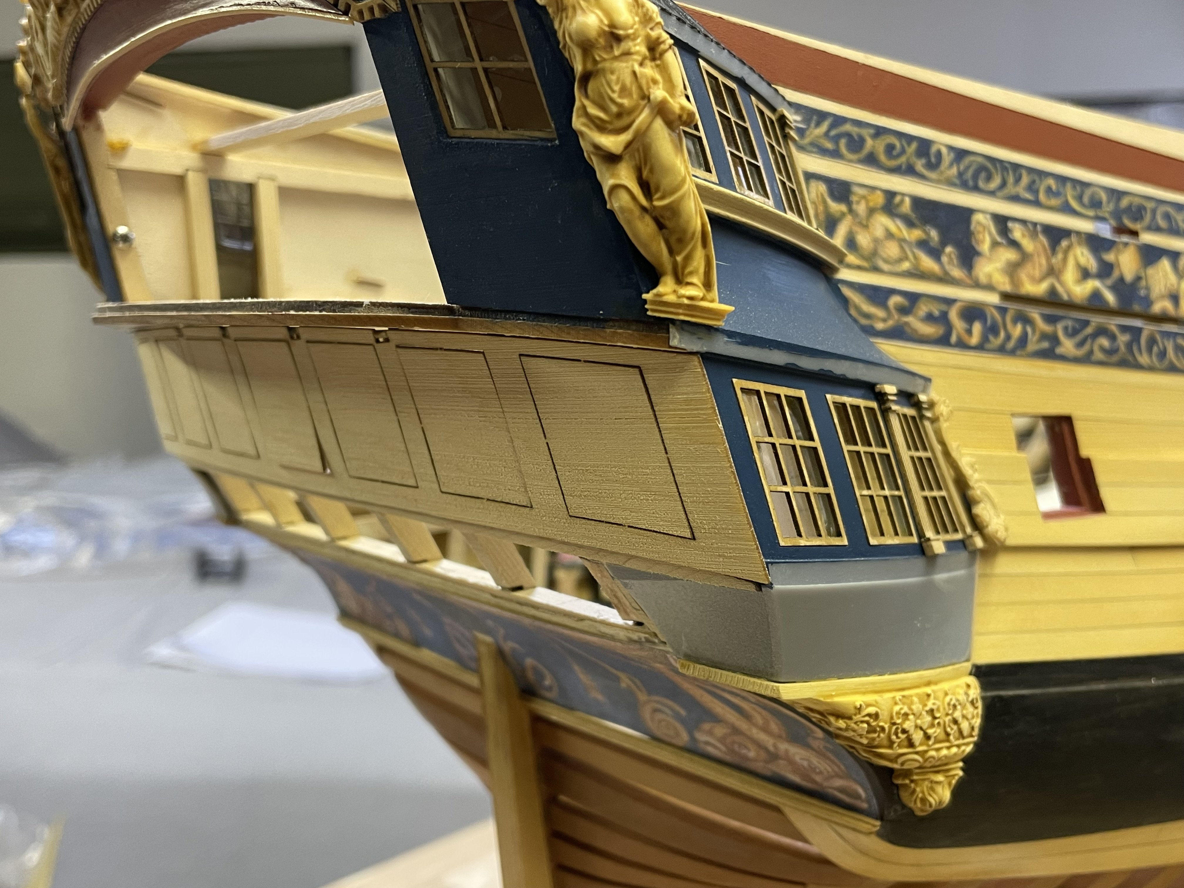
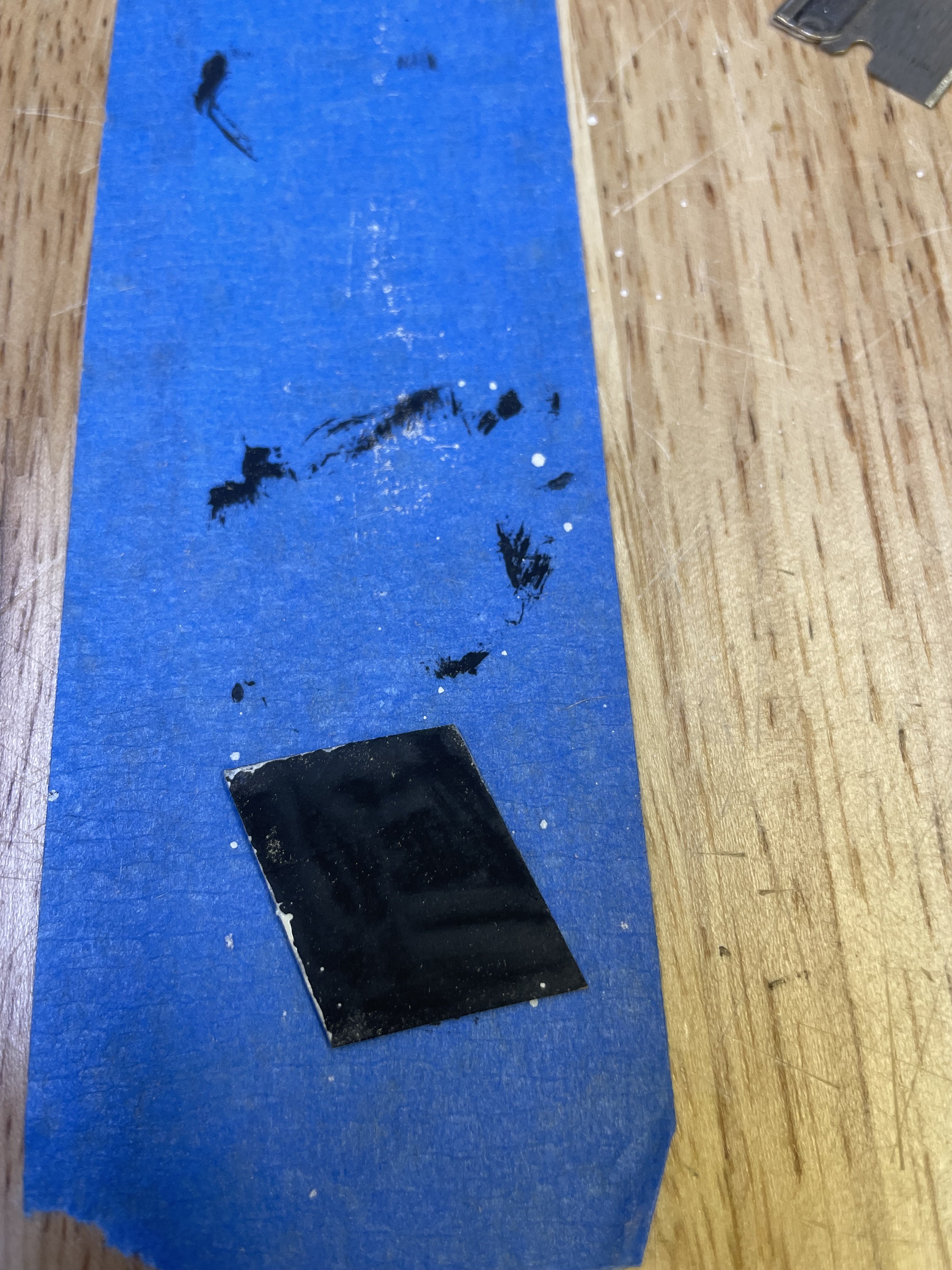
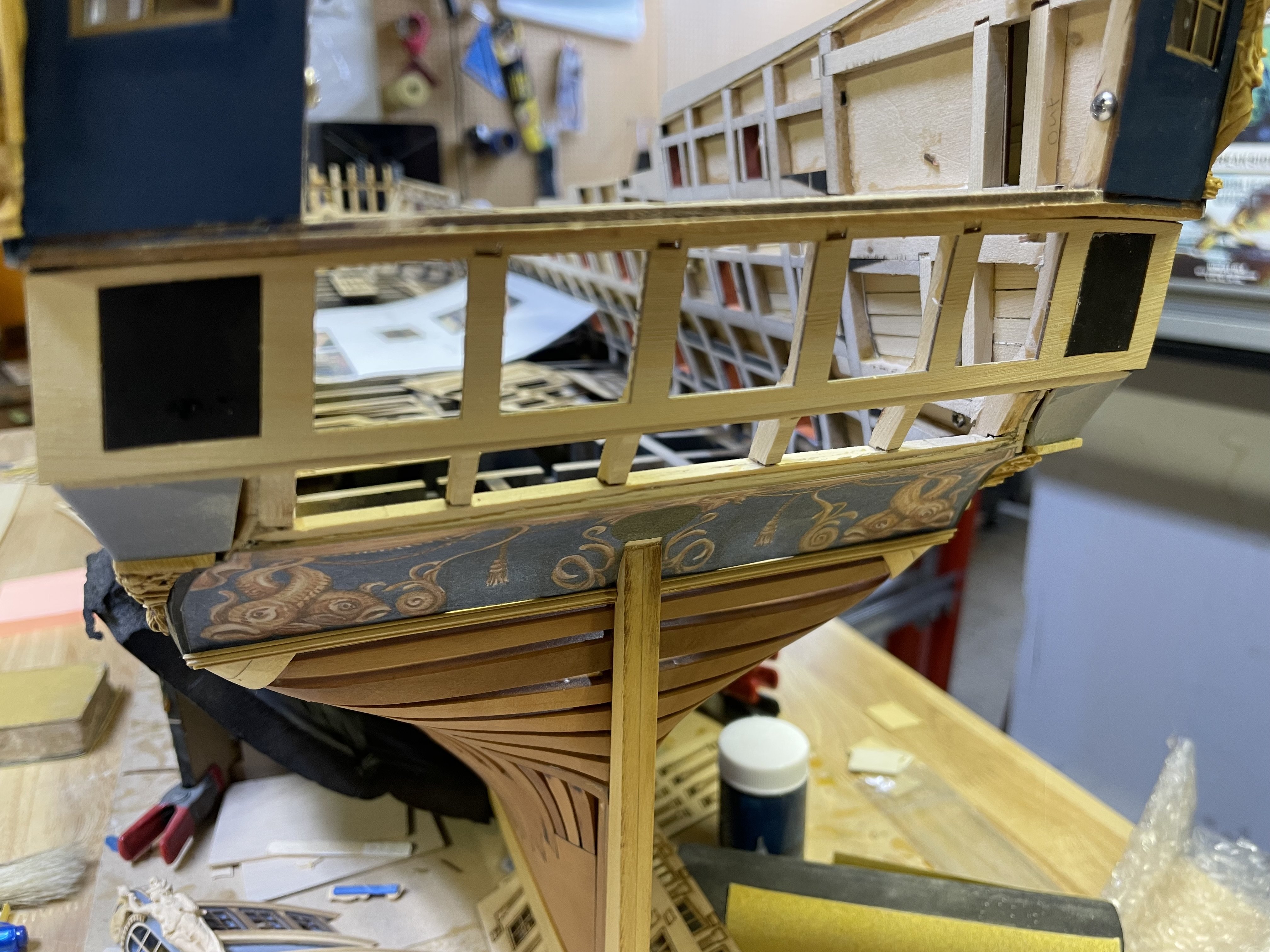
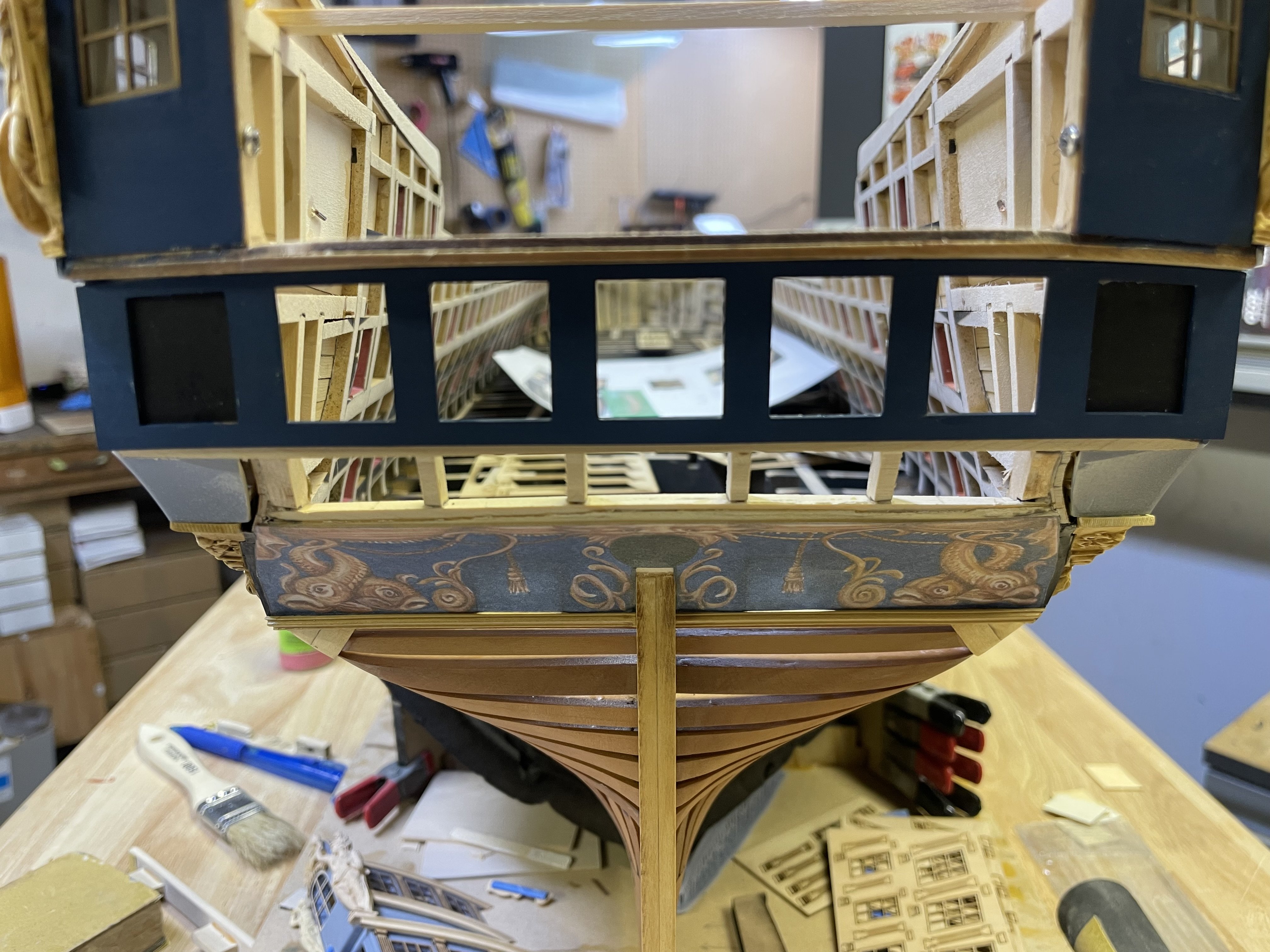
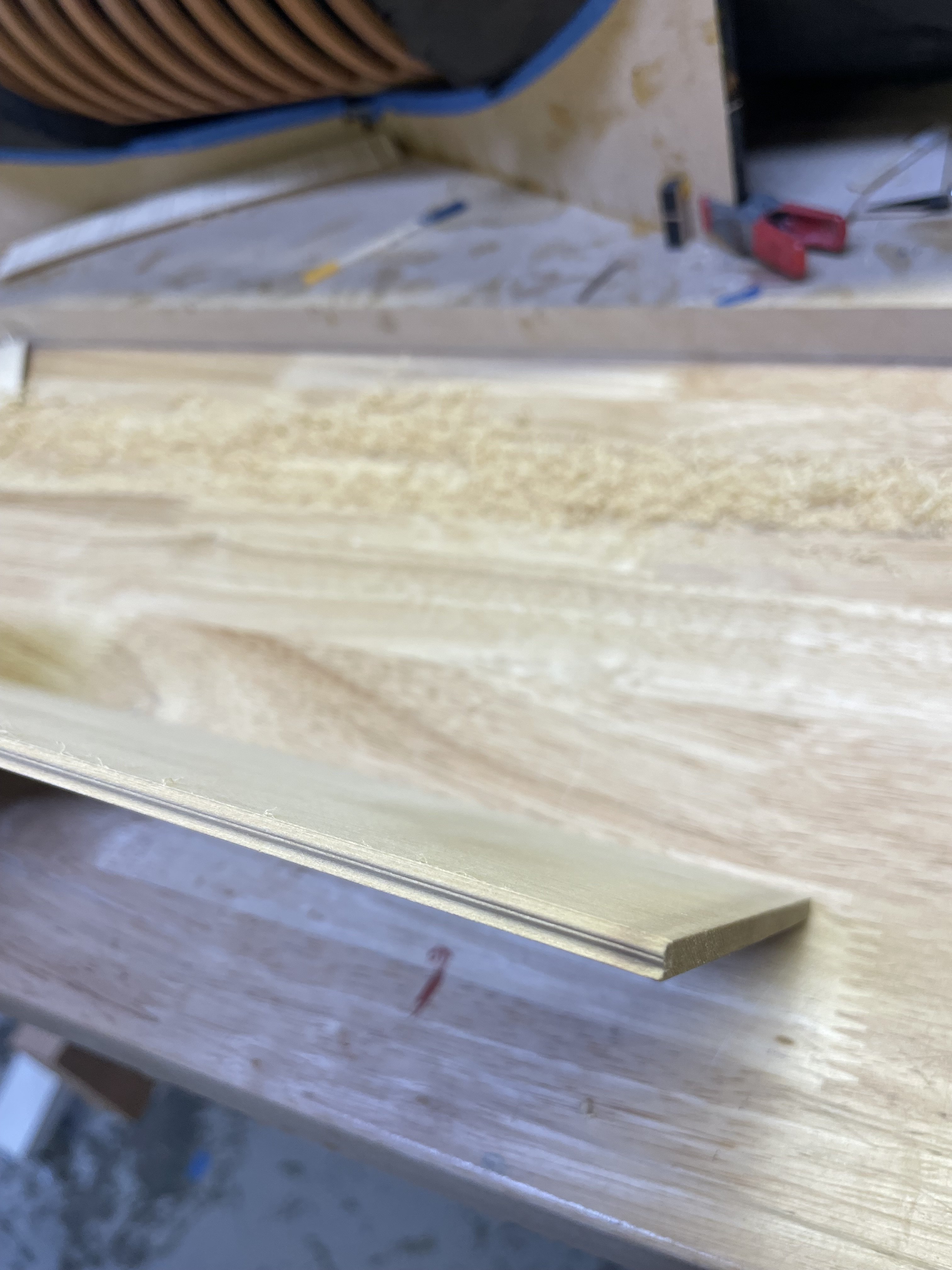
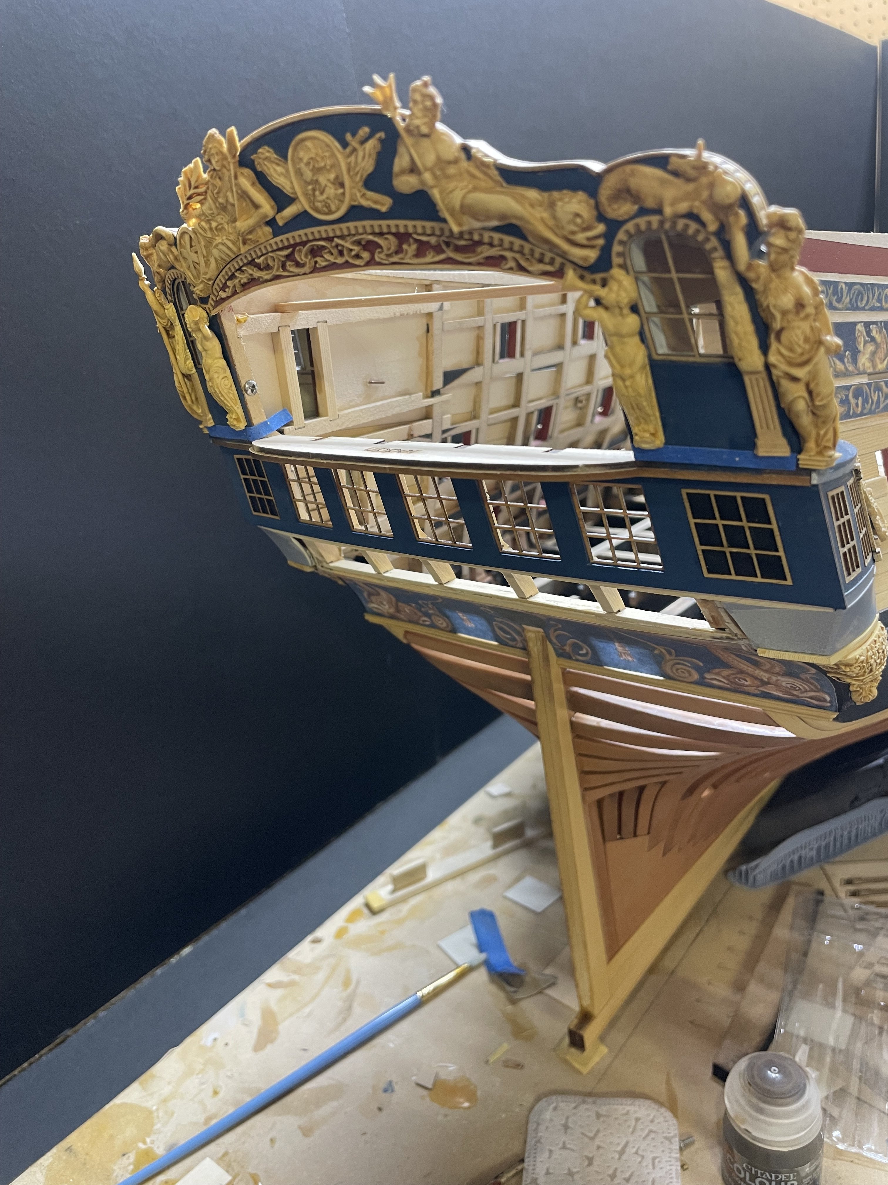
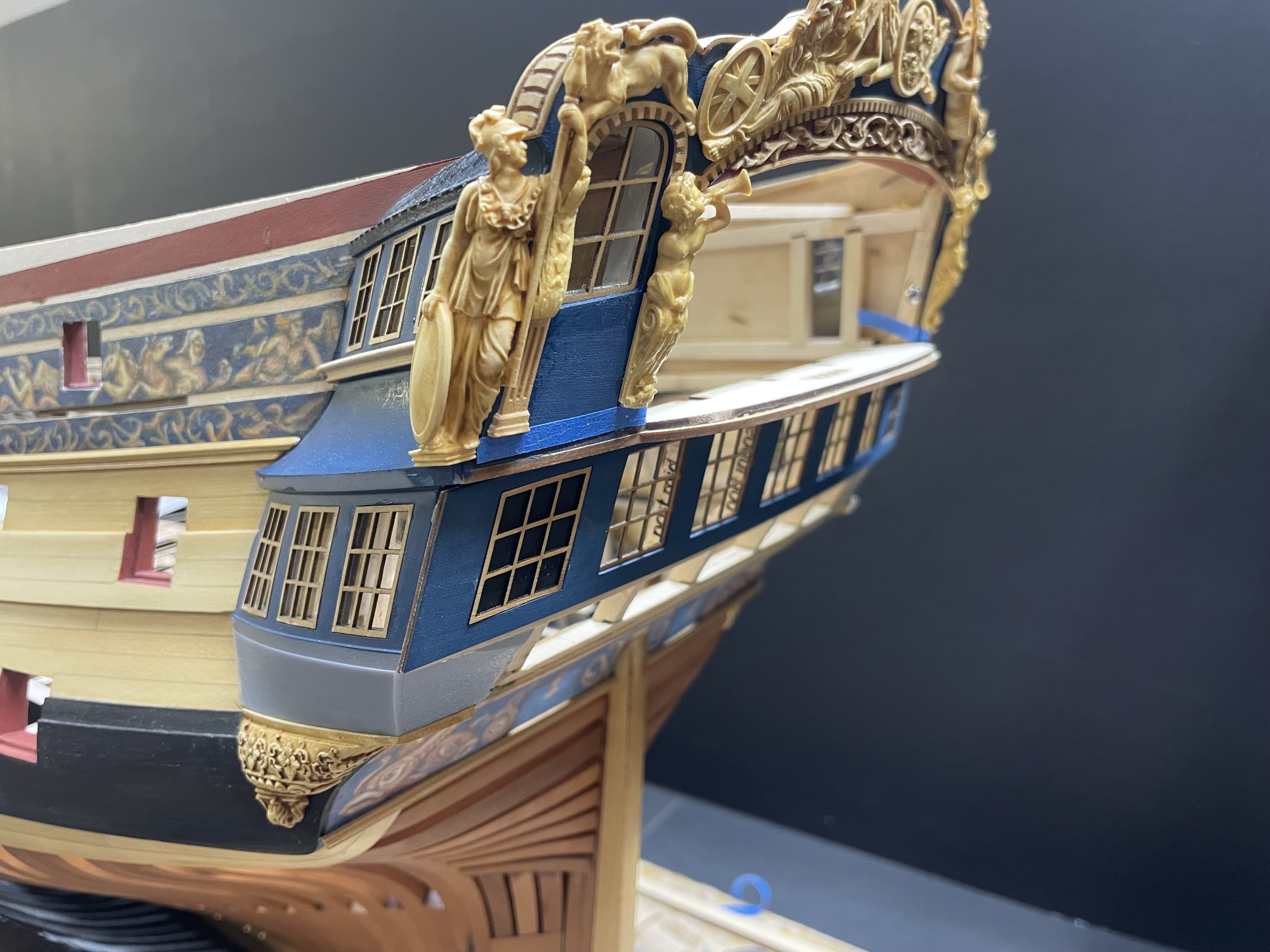
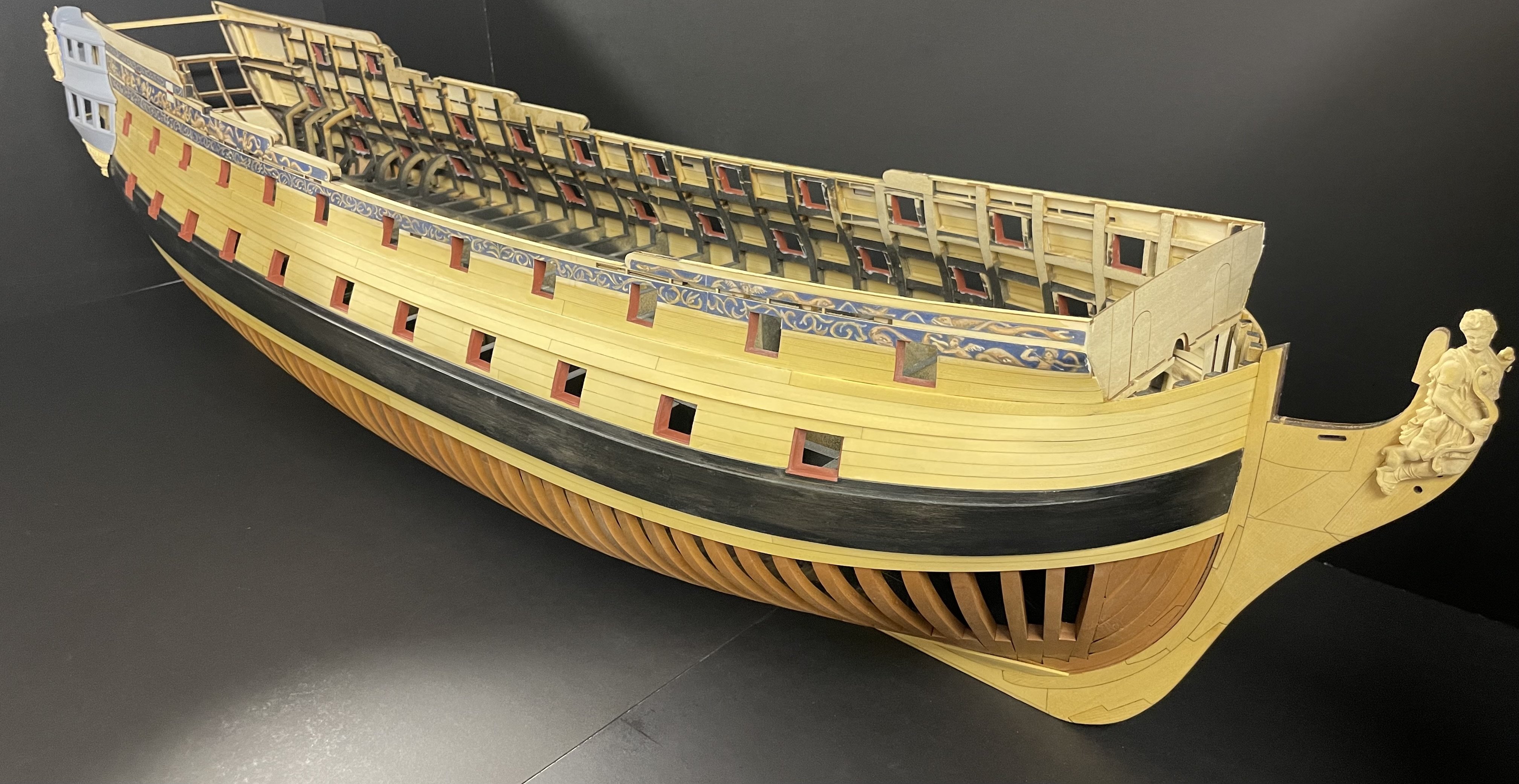
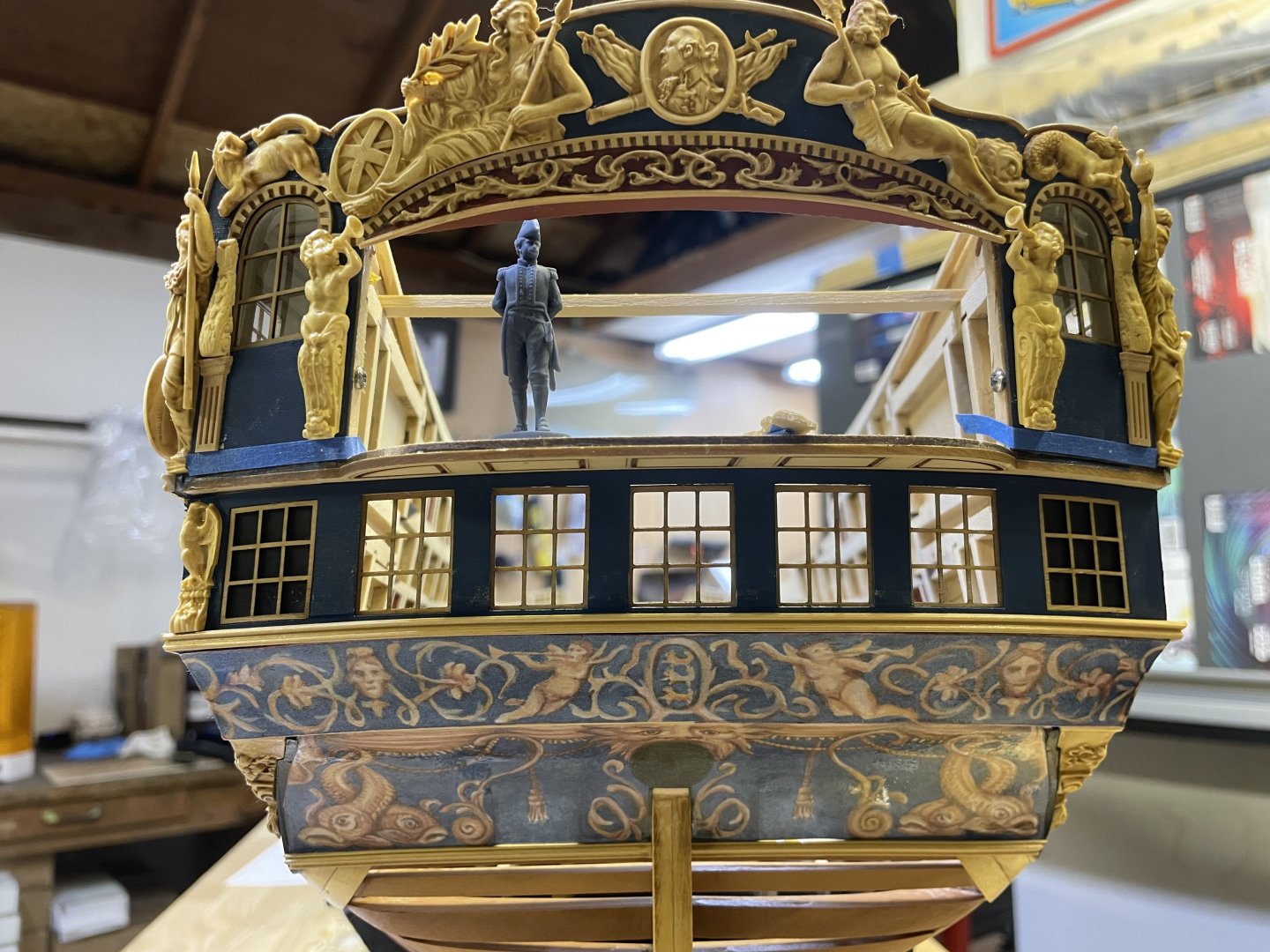
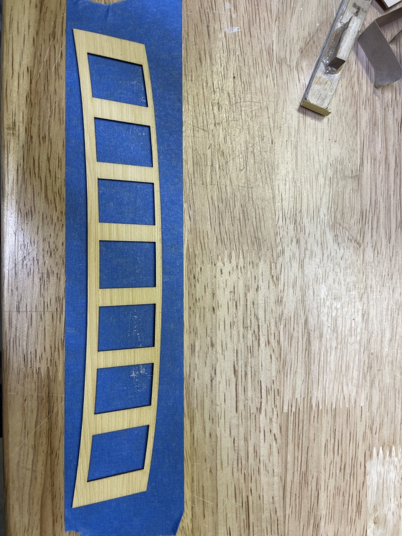
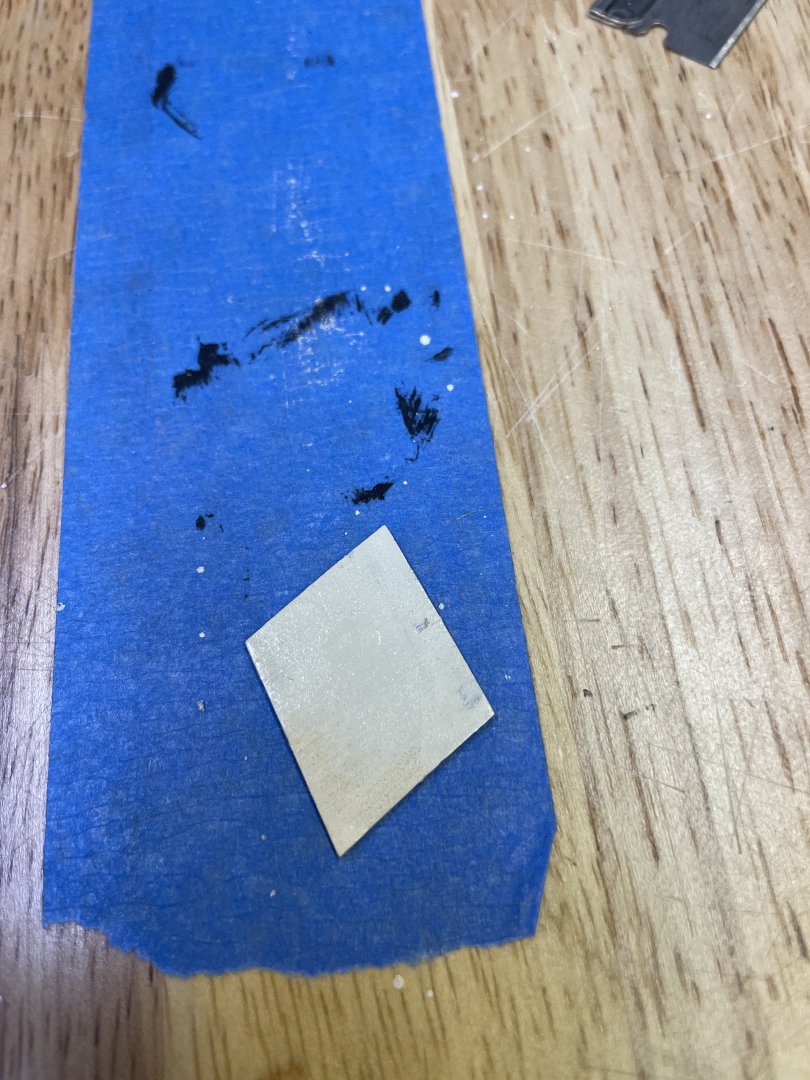
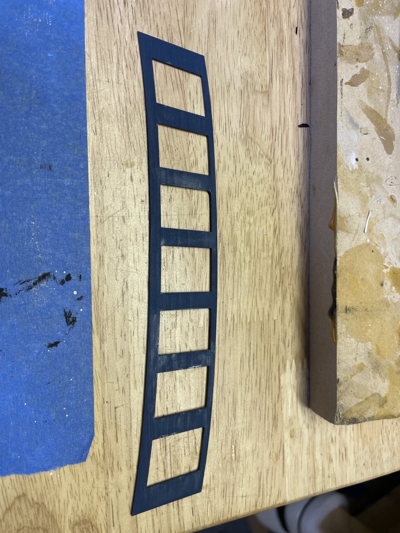
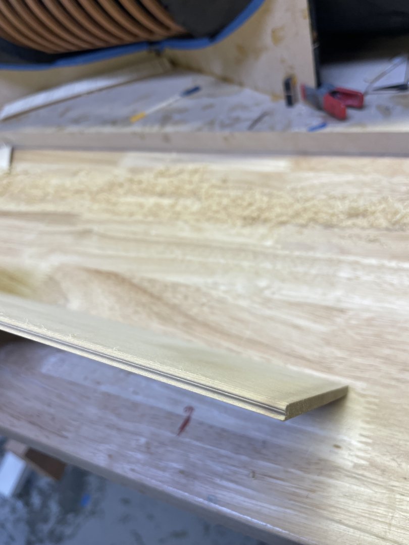
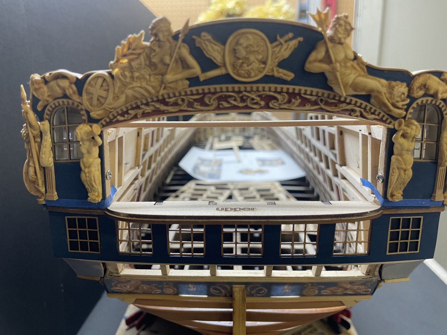
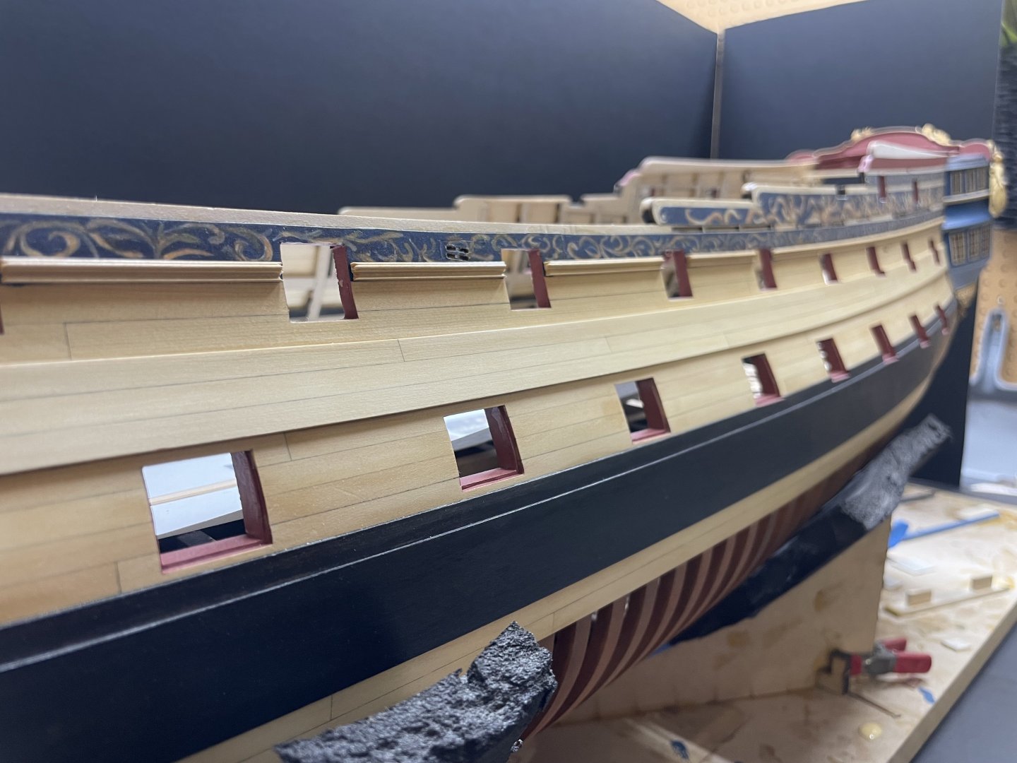
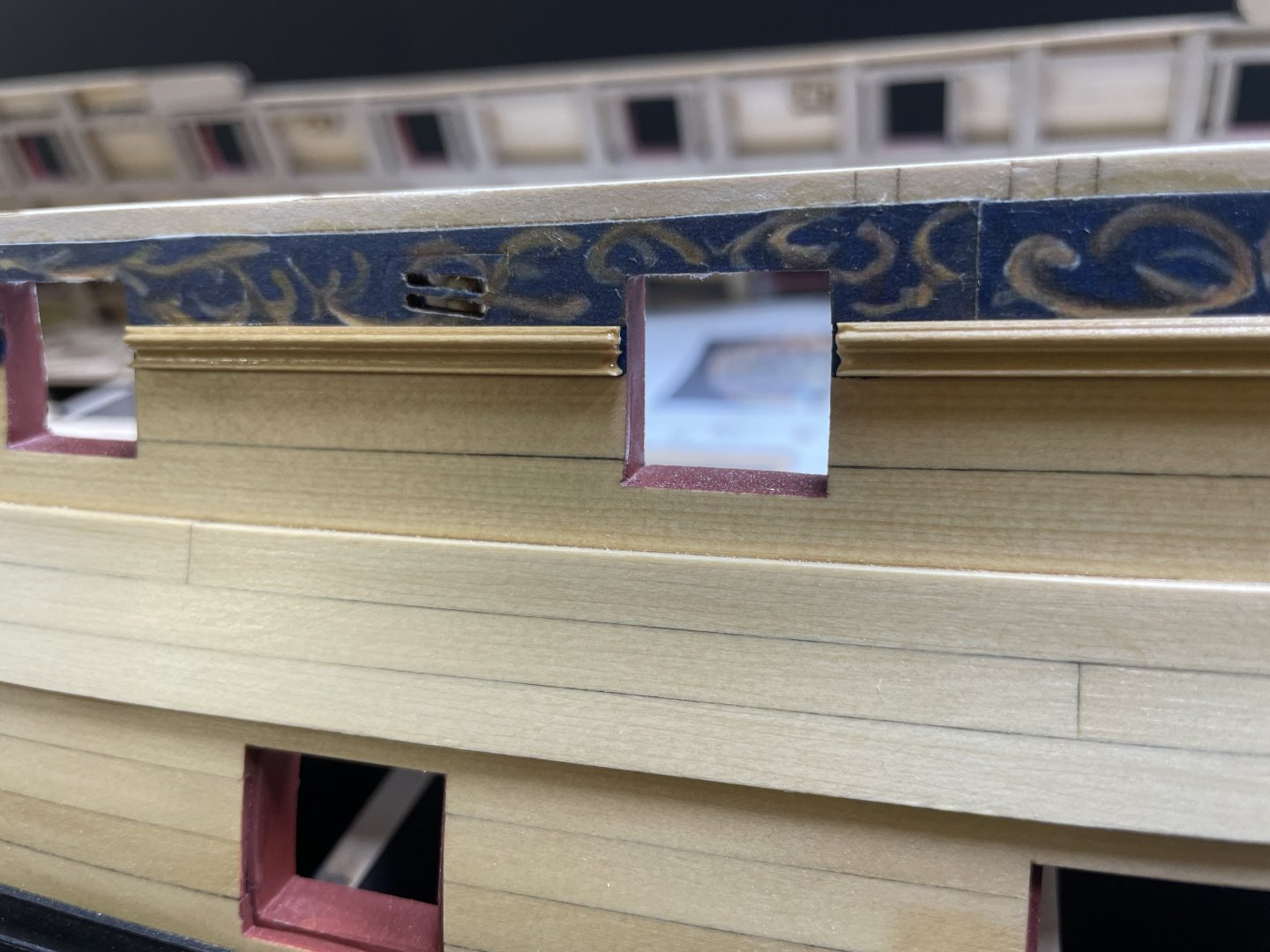
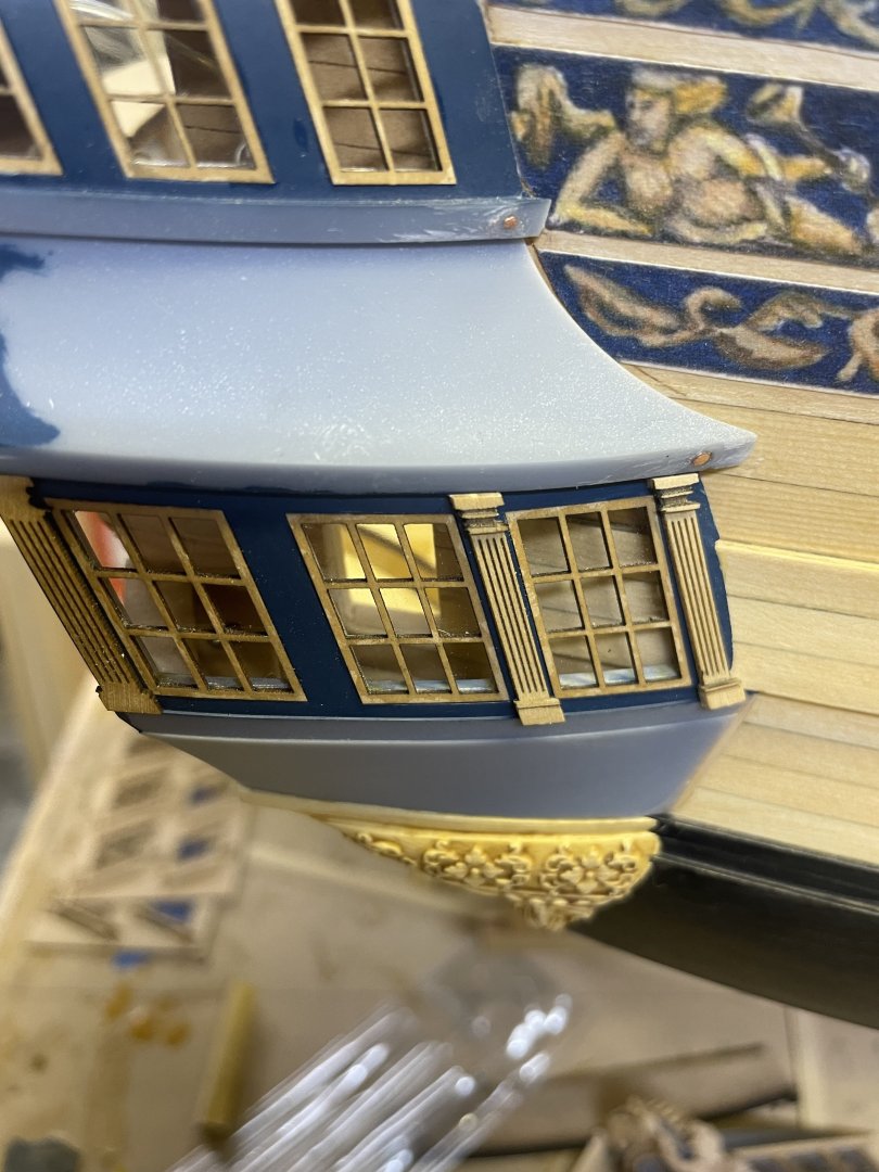
Ok I finally have some progress on Portland, things are moving along with Chapter 3. It’s turned out to be a bit larger scope of work than I anticipated so I’m going to cut it short with the moldings and Q galleries… I think. Anyway I have the windows and panels designed and fitting the transom on the upper deck . started with the inner panel which is 1/32, the window frames will end up sitting in this panel you can see the notches in the top, this will help align it with your uprights. Hopefully all that jig work will pay off! I went ahead and placed it up against the frames to see how it looked. I left a little wiggle room in the notches so it can be slightly adjusted to each side if needed. I think I moved mine over a pinch but not much. I left the window blanks in there with tabs to help strengthen the panel while it gets manipulated into place. after I was confident how it was going to fit I painted the inside face with the same color I used in the QG’s once I had it where I wanted it, while holding it down, I slowly started glueing it down from the middle outward with CA. Now it’s time to test fit the outer panel, this is pretty simple and the same process except no notches, I held it in place until all the window openings were centered over the inner panel (they are slightly larger) I also painted the backsides of the outer panels black, be sure to save these two blanks from the inner panel. Once they are dry go ahead and glue them in place. with the black out blanks in place it’s time to attach the outer panel, so go ahead and paint it blue, I’m using a darker blue for my model. I used the same glue process with this panel as well. Just slowly work your way from the middle out, you should have just about 1/32 showing around the inner panel from the inside. at this point the windows can go in, I skipped around waiting for the WOP to dry on them, they are just under 1/32 thick boxwood, they should fit right into the frames without issue. I’ll cover more in the instructions. While I was waiting to install the windows I started scrapping the lower larger moldings, these are .163” tall. I like to scrape the moldings from a board and then slice them off at the desired thickness with my saw. Seems to work very well. I completed the lower moldings on the port side and will continue up tomorrow. onward to the sculptures, this is always fun. The remaining carvings for the stern showed up yesterday from @Jack H and as usual his CNC work is extraordinary. I added the carving to the cove after I treated it with WOP and a bit of wash. I also added the sea boys and the baroque columns on the upper gallery windows. Still lots to go on the stern. Will resume work tomorrow and hopefully I’ll have some more updates.


- 404 replies
-
- 30
-
-
-
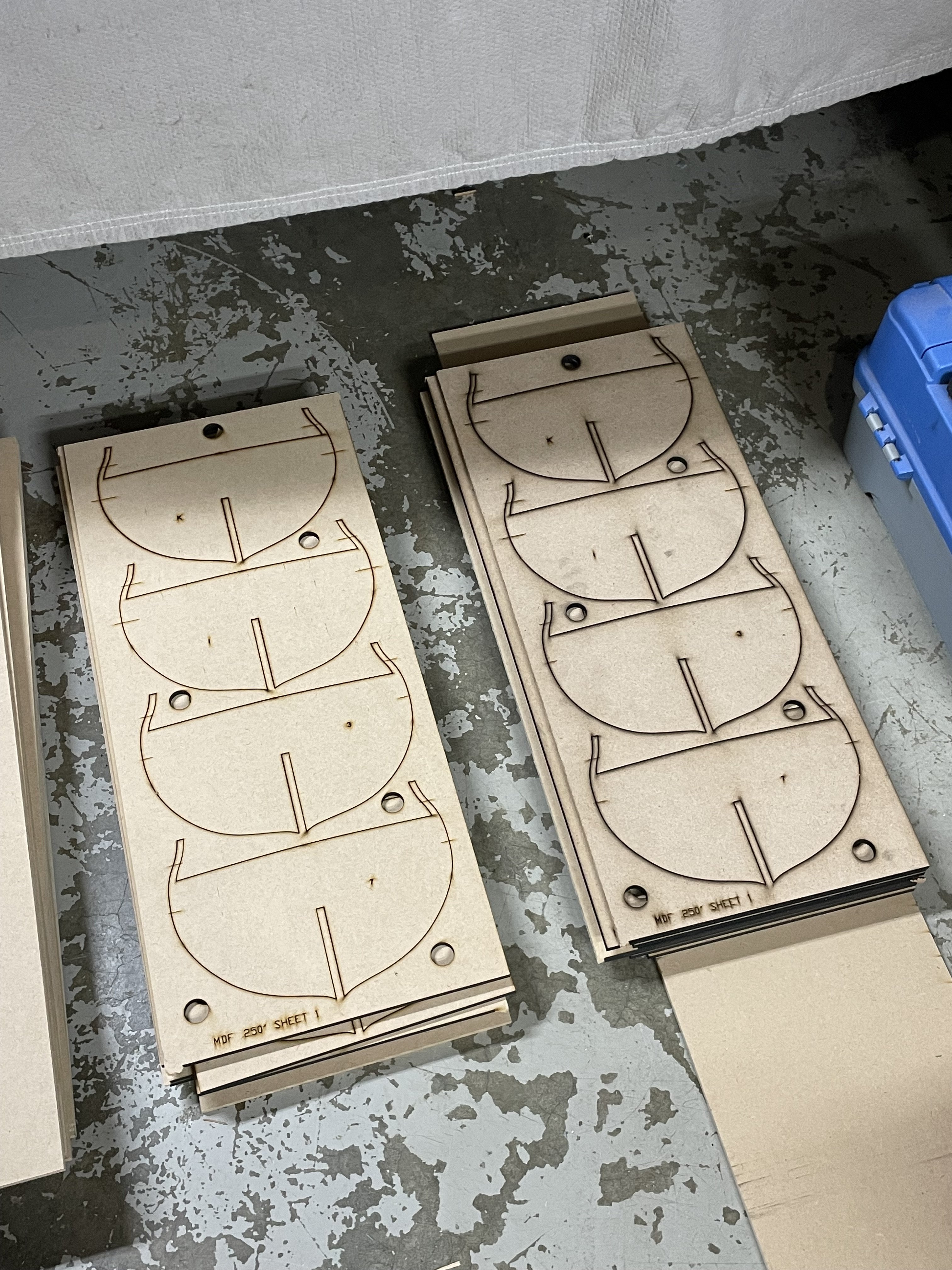
I made sheets of wood all day yesterday. My driveway looks like an AYC slaughterhouse. Few more cups of coffee and off to slaughter some boxwood.
-
Thank you Ronald!
-
I’m sure some of you folks have noticed my website is up and active except for the store, fear not I do have kits and chapters in stock for both Portland and Winchelsea as well as the capstans. I’m just working out some last minute bugs with the shipping function at checkout. I will have it going soon, when I do I will add all the inventory. I will post an update with things get moving. I’m also nearing completion of chapter 3 for Portland and will begin producing kits shortly after so stay tuned! JJ
- 11 replies
-
- 15
-
-
kit review 1:48 La Renommée 1744 - CAF Model
scrubbyj427 replied to James H's topic in REVIEWS: Model kits
Lovely work from Tom, what a fantastic design. This is on my list of things to do.- 20 replies
-
- 3
-
-
- cafmodel
- la renommee
- (and 1 more)
-
Thank you Dusan, and to you as well. Jack will be shipping goodies for Ch3 this week, so more updates coming in soon.
-
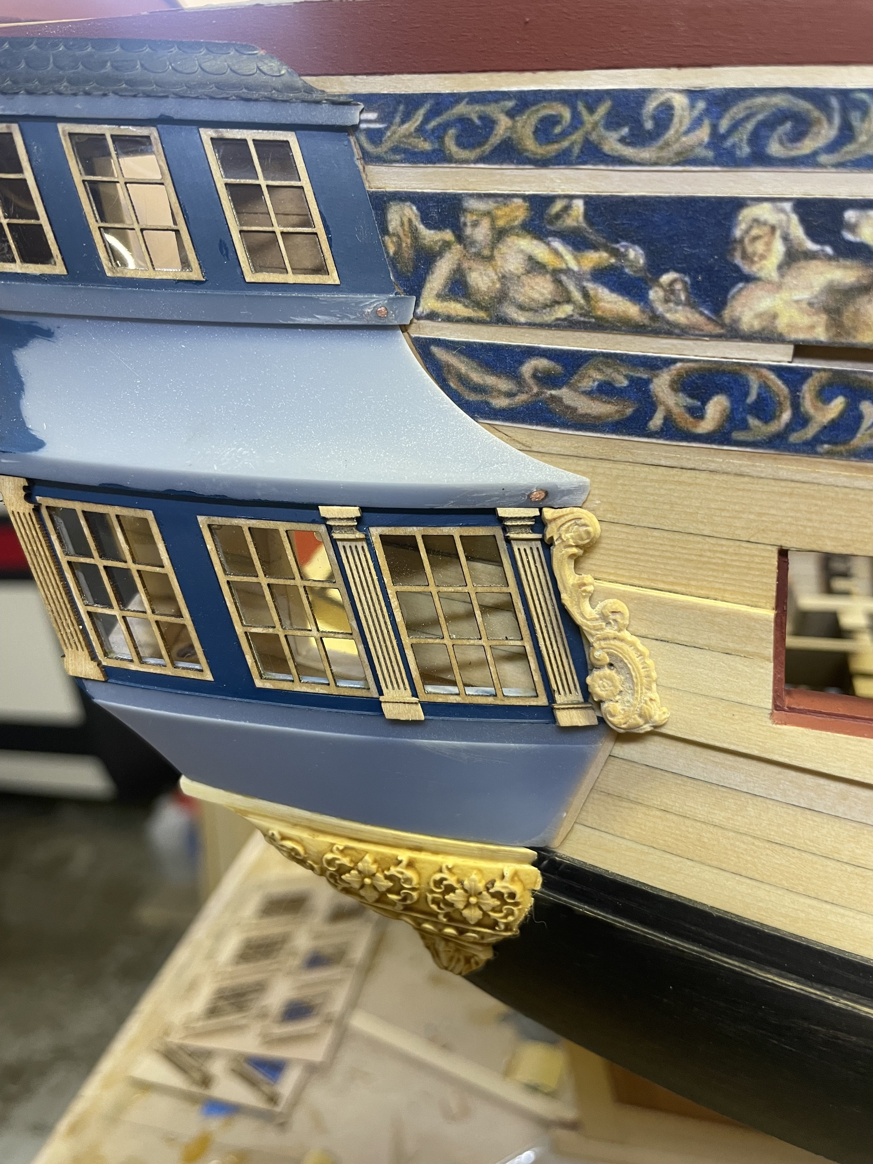
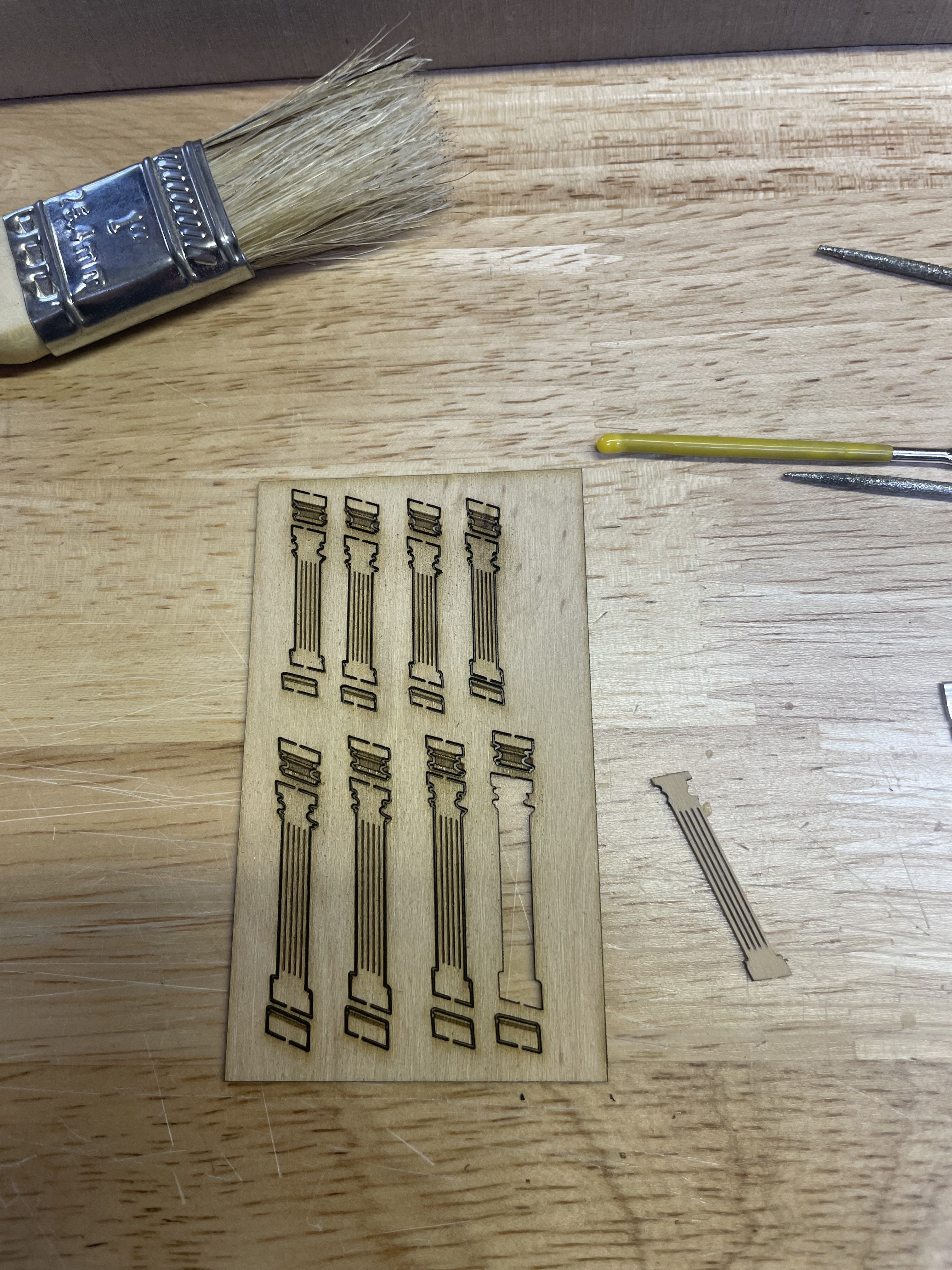
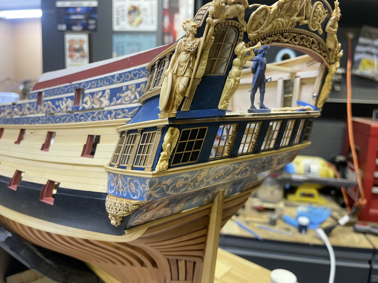
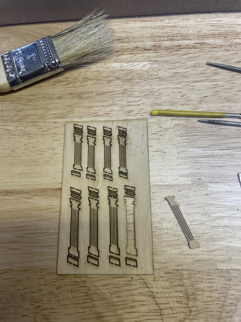
After a revision on the columns I decided to start adding some but I’m going to postpone install until after the QG moldings are on, the columns are 3 pieces and require that the smaller pieces be added to match the surfaces of the adjacent moldings..if that makes sense. Anyway these are just sitting dry fit and I will finish them off once the boxwood molding goes on.
- 404 replies
-
- 19
-
-
Excellent work Steve! Your Winchelsea is looking great!
-
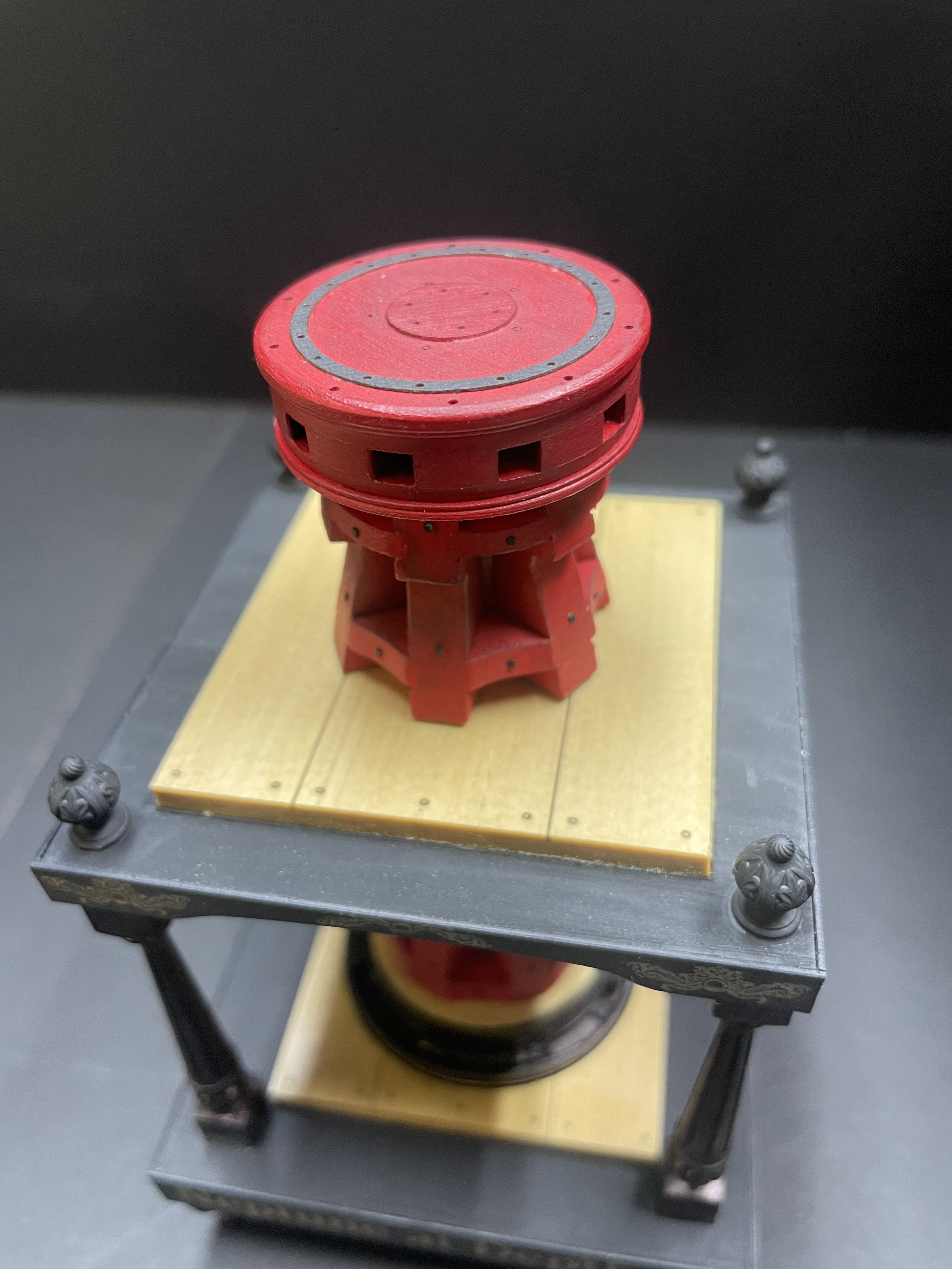
Hey everyone, I've been hard at work here getting some Syren kits produced in between Portland prototype work. Here’s the capstan kit that Chuck designed, it’s a nice simple little model to assemble but quite complex and detailed as we all have come to expect from Chuck. I’ll have these in stock on my website hopefully by next week along with Winchelsea starters and ch 1 and 2 following.

-
Yes it’s not quite finished. needs some revisions and changes made. It will be linked on MSW once it’s ready.
-
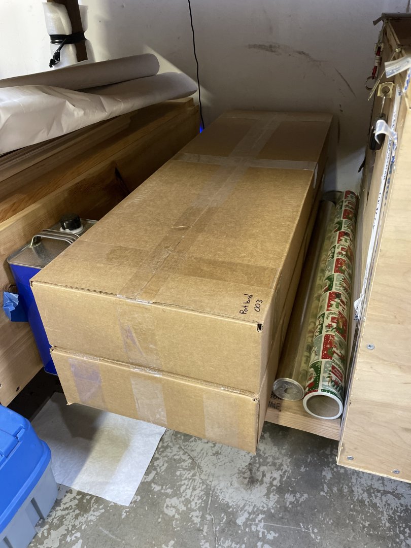
Ok I have two Pear framed Portland kits ready to go and two Winchelsea bulkhead starters that aren’t yet boxed, will be in a few days. Capstans next. Portland prototype updates for chapter 3 coming next week. Also Winchelsea chapter 1 and 2 kits in AYC and cherry coming next week


-
I think that center 65kw generator is a waste of space….
-
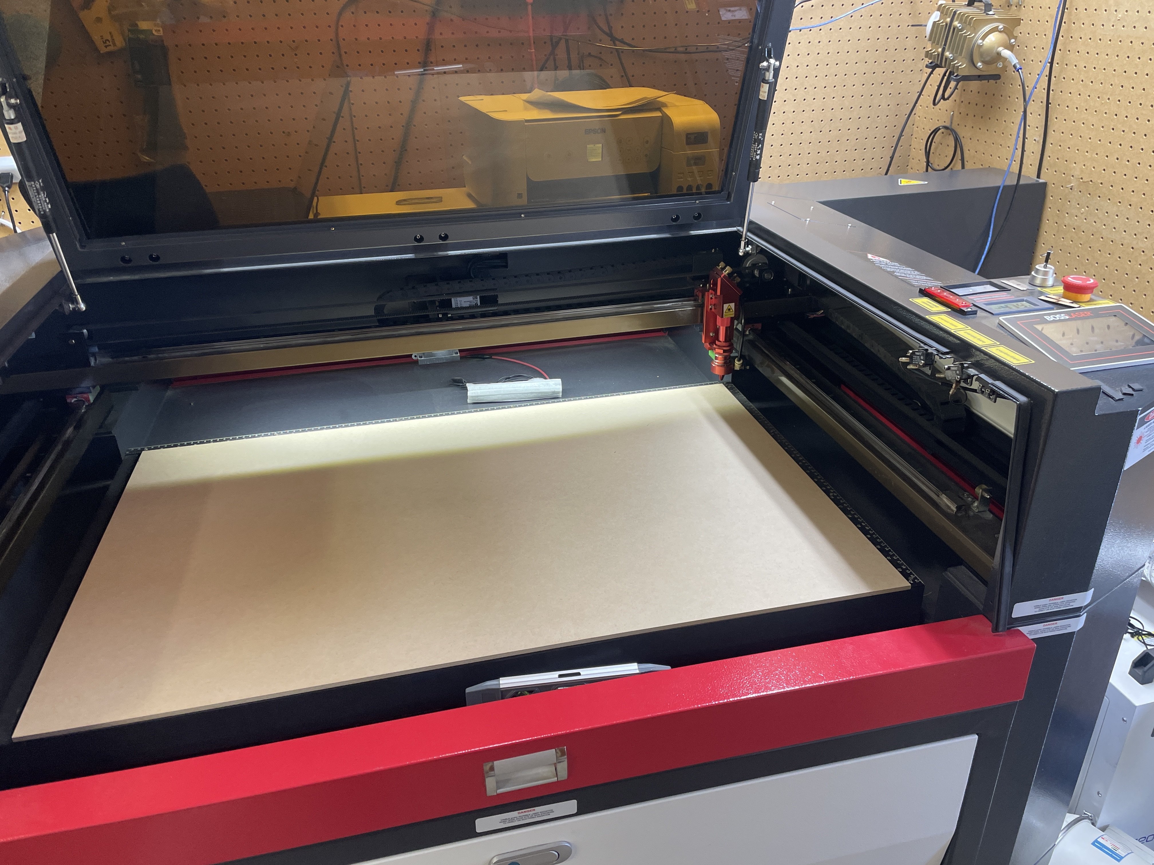
Update: My laser decided to take new years off until further notice so everything is at a dead stop until I can convince it otherwise.
-
Beautiful work Ben! It’s looking really good. Did all the inner support structure come out easily?
-
I will let you know when I have a cherry one completed.
-
Not sure exactly what you’re asking but It sounds like separate bow and stern model sections? No I will not be producing those as this time, just the whole ship.