Stuntflyer
-
Posts
1,135 -
Joined
-
Last visited
Content Type
Profiles
Forums
Gallery
Events
Everything posted by Stuntflyer
-
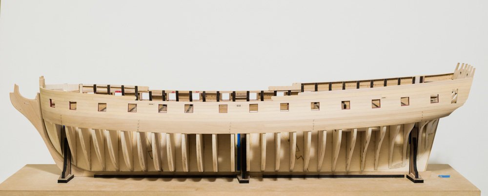
 Work continues with the rather messy job of fairing the inner hull above the wales starboard side. Frame width has been reduced to 6" or 1/8" actual. Mike
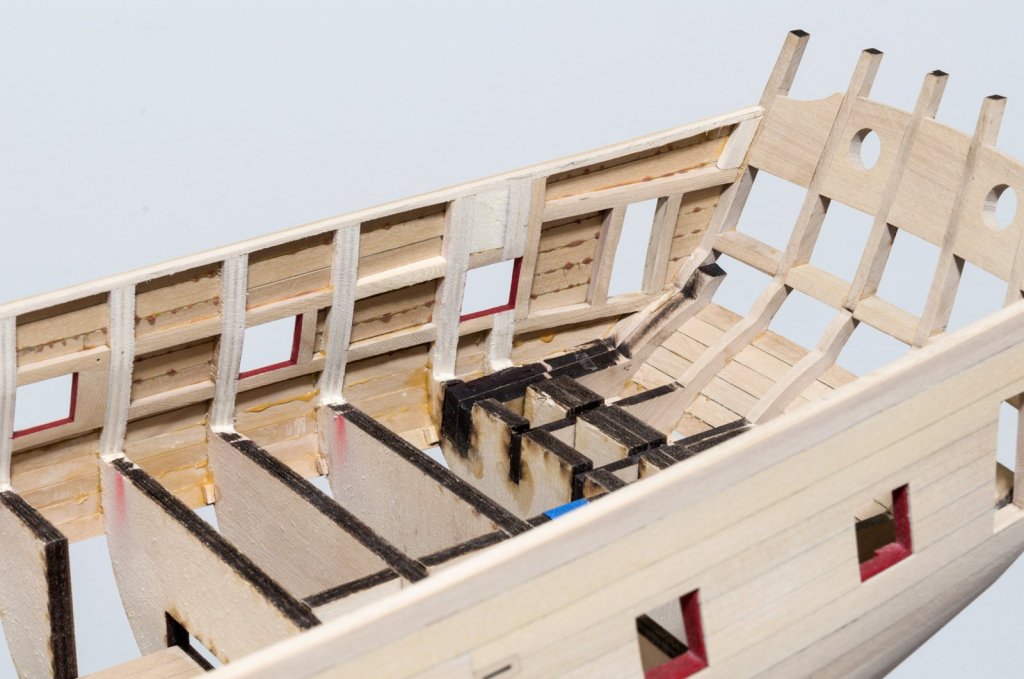

- 607 replies
-
- 30
-

-
- winchelsea
- Syren Ship Model Company
- (and 1 more)
-
Thanks, Mauricio! Most of the wood used on my build went into making the frames. To calculate the amount of wood needed, I first had to cut out all of the paper patterns corresponding to each frame. The patterns were then grouped together according to the thickness of wood needed for those patterns. Once that was done I was able to layout the patterns, paying close attention to the run of the grain, on several sheets of paper. The sheets of paper were the same size as the sheet wood I would be ordering. I figured in a waste factor of 50% for re-do's. Mike
-
Thanks, Mark! I have fretted about it too and decided not to paint those edges. Guess I'm not a purist! Mike
- 607 replies
-
- 5
-
-
- winchelsea
- Syren Ship Model Company
- (and 1 more)
-
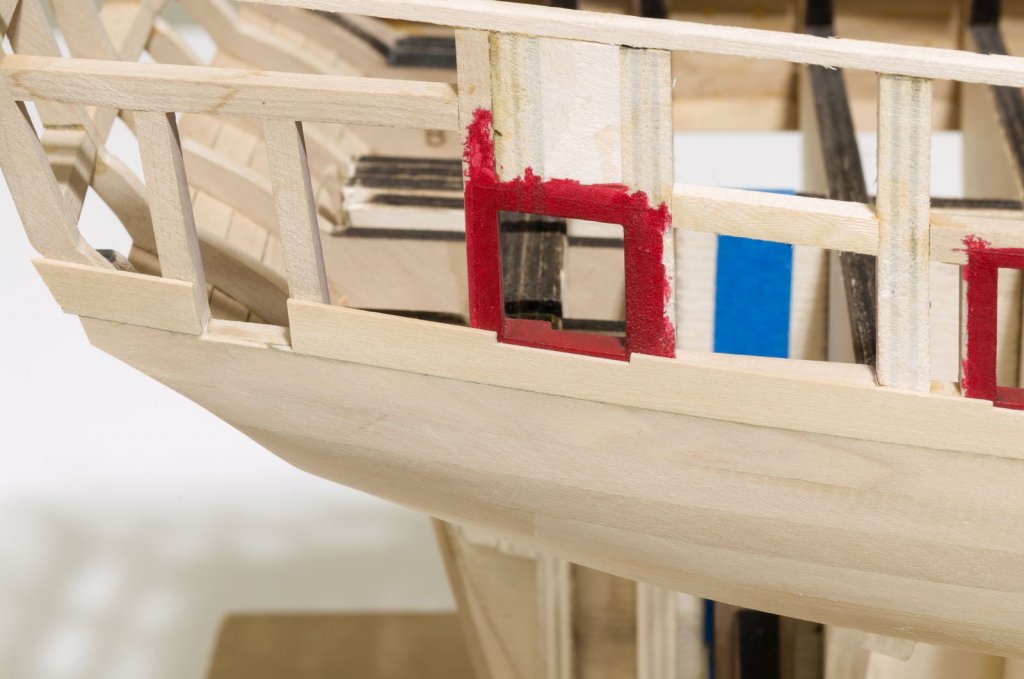
The port side planking above the first layer wales is done. Again you can see the original wood color in the area of the wales compared to that which is above. I pencil marked X's on the first layer wales so as to avoid placing the second layer in the wrong location. I also started to clean up and fair the inside of the hull in the forecastle area. I glued scrap 1/8" basswood and balsa in-between the frames as a guide while removing material. Lots of sawdust! MIke
- 607 replies
-
- 34
-
-
- winchelsea
- Syren Ship Model Company
- (and 1 more)
-
Excellent work as usual, Chuck. You certainly know your way around AYC. I'm still learning! Mike
- 421 replies
-
- 3
-
-
- medway longboat
- Syren Ship Model Company
- (and 1 more)
-
Thank you all for the very nice comments and for all the"Likes"! Mike
- 607 replies
-
- 4
-
-
- winchelsea
- Syren Ship Model Company
- (and 1 more)
-
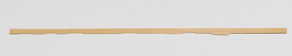
Steve, the planks with no tabs are 1/4" x 3/64 and the tabbed ones are 5/16 x 3/64" Mike
- 607 replies
-
- 7
-
-
- winchelsea
- Syren Ship Model Company
- (and 1 more)
-
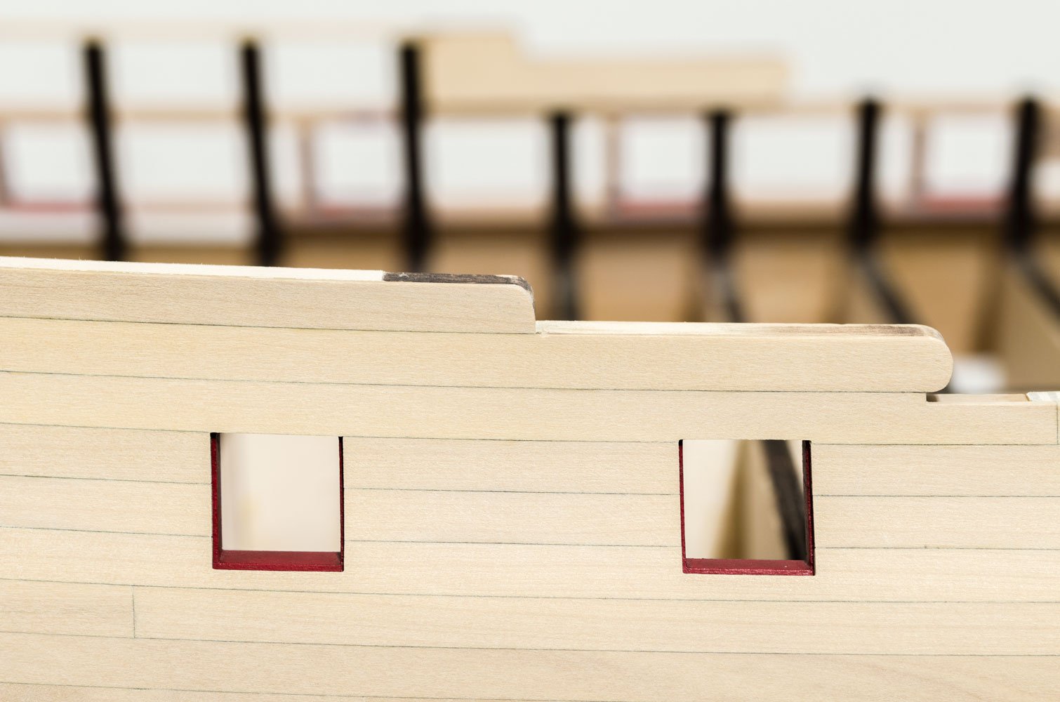
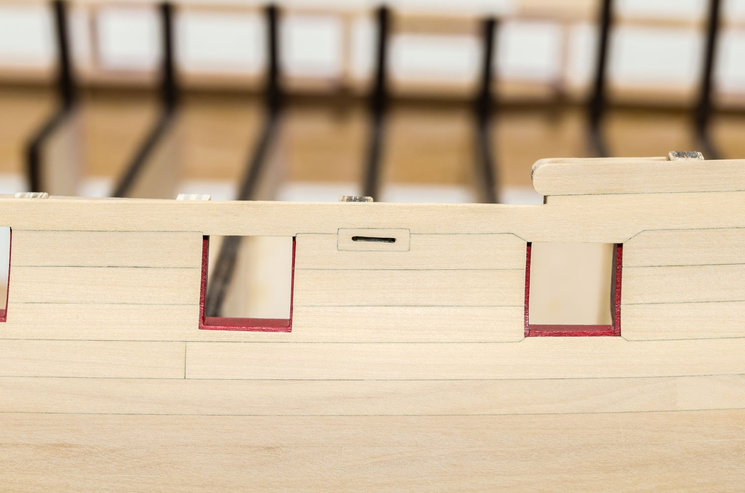
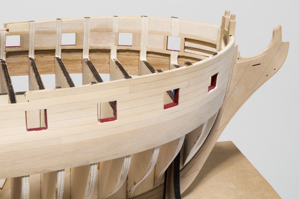
The planking work above the wales on the starboard side is finished. I think you can see the difference in the newly purchased wood compared to that which was used for the first wale layer. It is much more even in grain and color. The most difficult work was shaping the planks that have both tabs and cutouts. Mike


- 607 replies
-
- 37
-
-
- winchelsea
- Syren Ship Model Company
- (and 1 more)
-
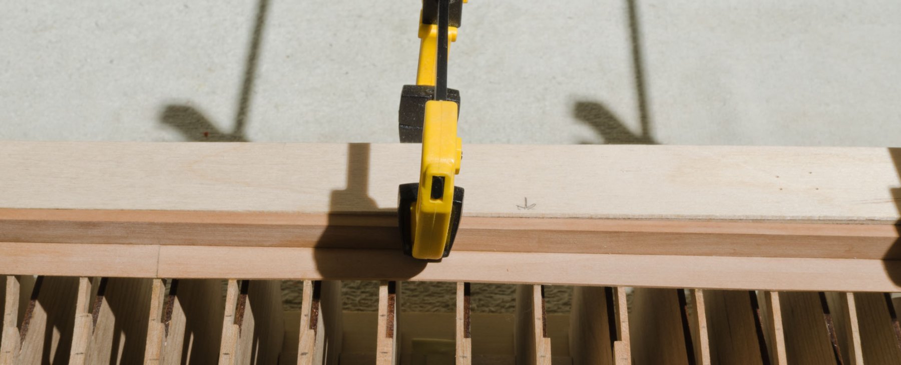
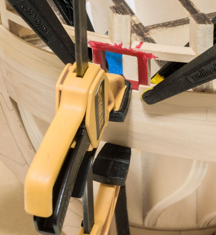
Thank you, Ken! I only use clamps with protective tips. Here is an example of the clamps I use and how I set them. Those are 2" Wolfcraft clamps which are used to pull the plank against the hull. http://www.wolfcraft.com/en/products/p/microtip_spring_clamps/2_microtip_60_precision_spring_clamps/s/p/index.html The 6" Dewalt clamp is used to pull the plank down tight to the previously installed plank. I usually glue and clamp 4"-6" of planking at a time. No matter how many I use there is no chance of denting the boxwood. Mike
- 607 replies
-
- 24
-
-
- winchelsea
- Syren Ship Model Company
- (and 1 more)
-
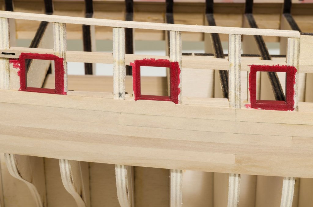
Lou: This version uses a thicker and better grade of wood for the bulkhead former and bulkheads. Filler blocks are not necessary. Chuck has supplied me with some nice boxwood sheets for planking, so I am finally ready to start work above the black strake. Cutouts or tabs are made where necessary in the area of the gun ports. I'm using clamps and Titebond II. Sanding will be done after all of these planks are in. Mike
- 607 replies
-
- 34
-
-
- winchelsea
- Syren Ship Model Company
- (and 1 more)
-
Chuck likes CA and it works great for him. I tried his method, but I prefer using Titebond II. It requires more work since I have to hold the plank or lightly clamp it while the glue sets. Guess that's why I have a TV in the workroom. Mike
-
Here is a small update on the planking progress so far. The biggest challenge is getting a good fit at the stem where bending and twisting is necessary. Be careful when clamping the wood as it can dent easily. Place a flat piece of wood under the clamp or use a trigger clamp that can be controlled. Also, place the clamps across the entire width of the plank in order to avoid any chance of splitting the wood when twisting it into shape. A hair dryer on dry wood is all that's necessary. I have only done some minor glue cleanup of the seams. The planks are only 1/32" thick, so better to do the final sanding over a broad surface, I think. Mike
-
Well, having seen Chuck's Longboat in AYC I decided that I much preferred that look over what I was getting from the Pear. So, off to the races again with another re-do. Things are now close to where I was a month ago. I like the fact that there is much less char build up on the AYC. The stem/keel joints were glued together without any char removal. The wood is quite flexible which makes the planking process easier. I'm holding off on the final fairing of the two aftmost bulkheads and transom until I get a better idea of just how much more is needed. As I move further up the hull I will start to sand those butt joints. Right now it would be easy to sand them too thin. Here are a few photos of where I'm at now. Mike
-
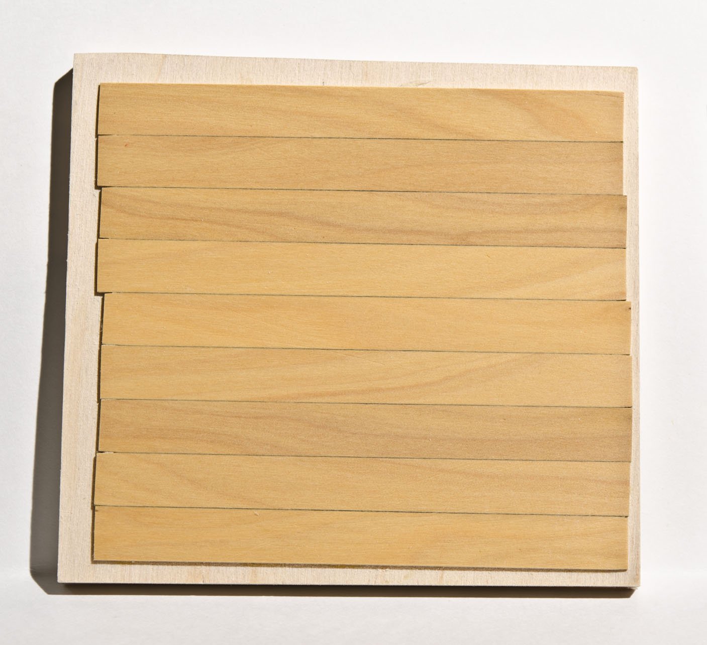
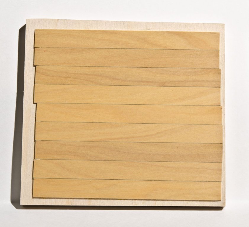
Jorge, I'm on hold while I continue to try and find some nice boxwood for the hull planking. The stuff I have now has too much visible grain. Here is an sample I made to simulate the planking with some Wipe-on-Poly applied. Some folks might like it, but I prefer a less grainy look. This is a major project and I don't want to compromise unless I have to. Mike
- 607 replies
-
- 14
-
-
- winchelsea
- Syren Ship Model Company
- (and 1 more)
-
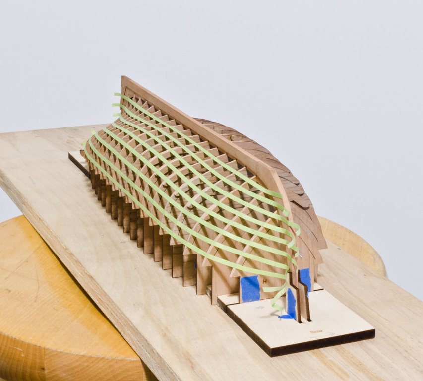
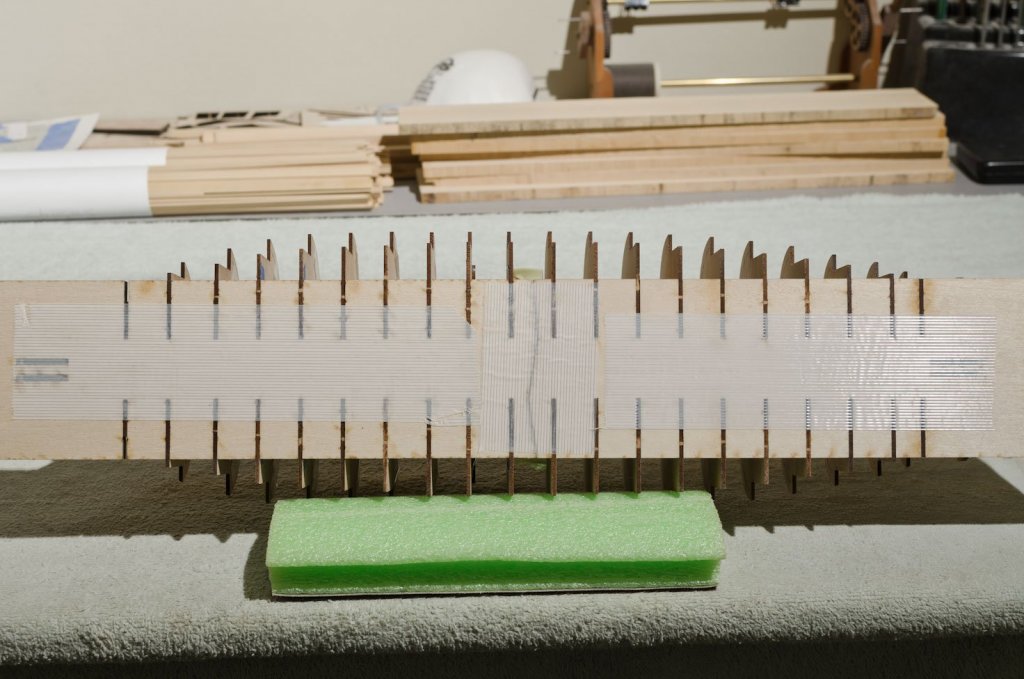
After completing the hull fairing on one side of the hull, I worked on lining it off. Here I used 1/8" painters tape. The bow area is a bit tricky to do and I anticipate some minor adjustments later. Prior to installing the garboard the keel is held straight with a length of 1/4" x 1" ply. So far, it appears that these pre-spiled planks are made slightly oversize, leaving room for adjustments. Mike


-
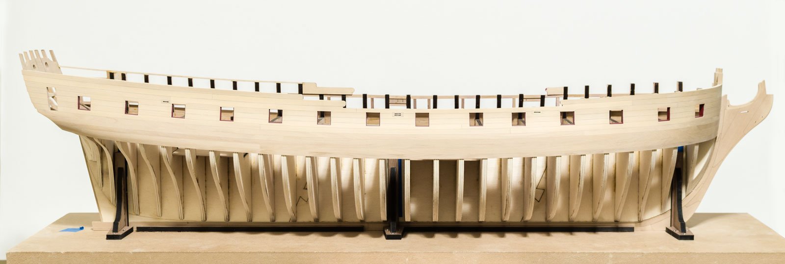
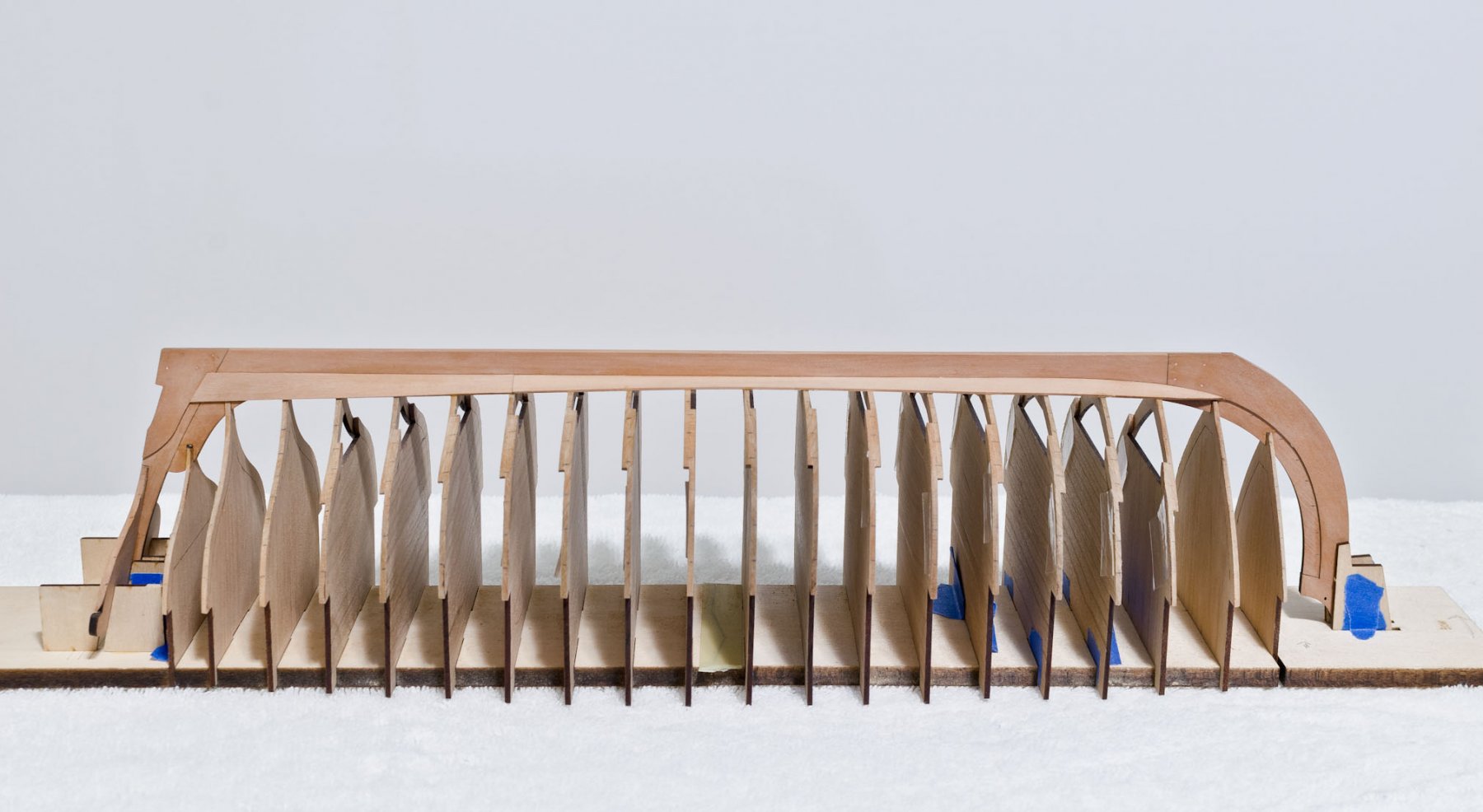
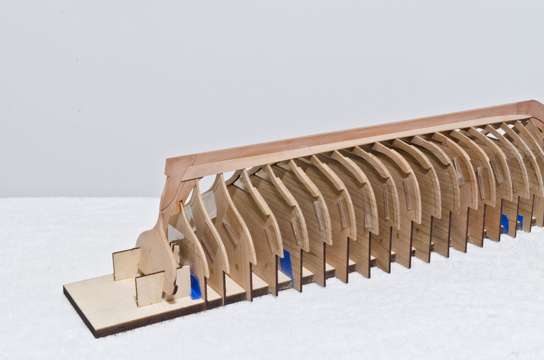
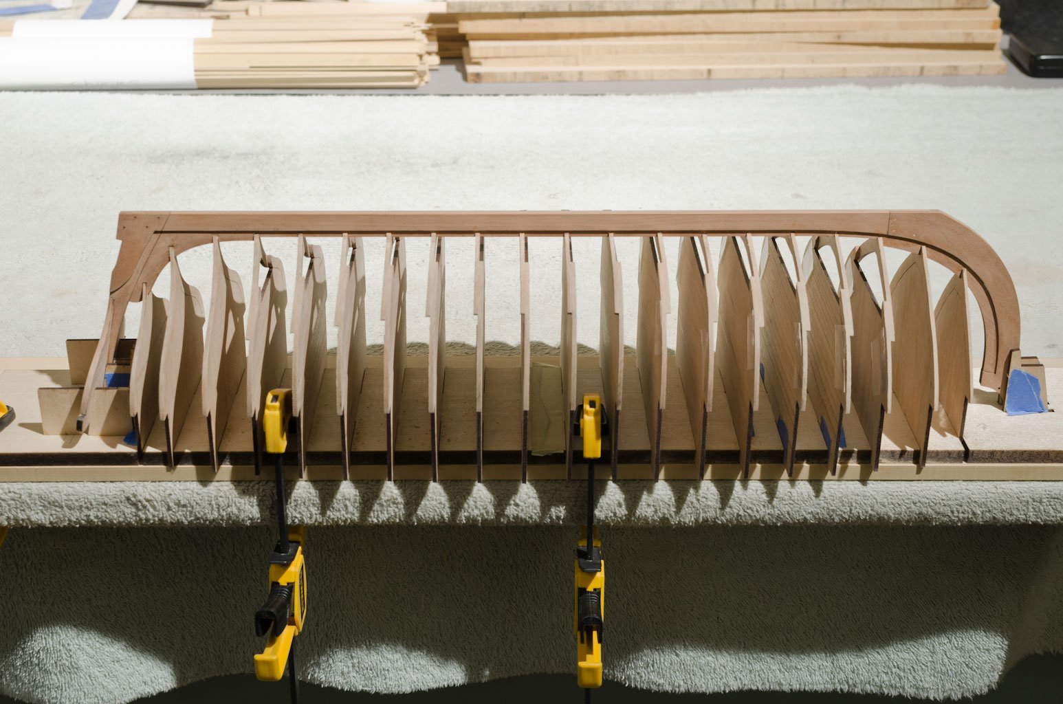
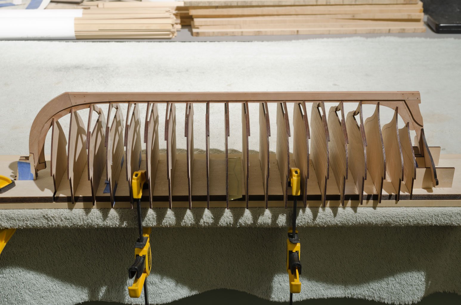
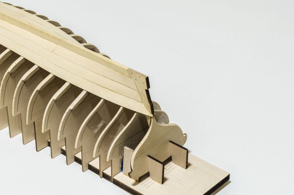
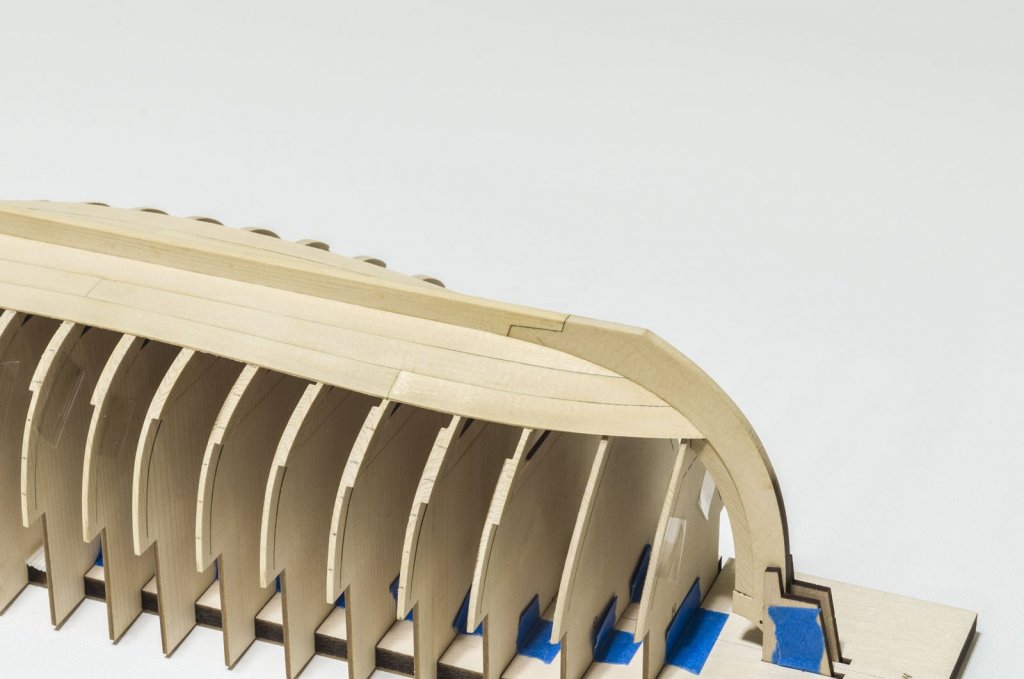
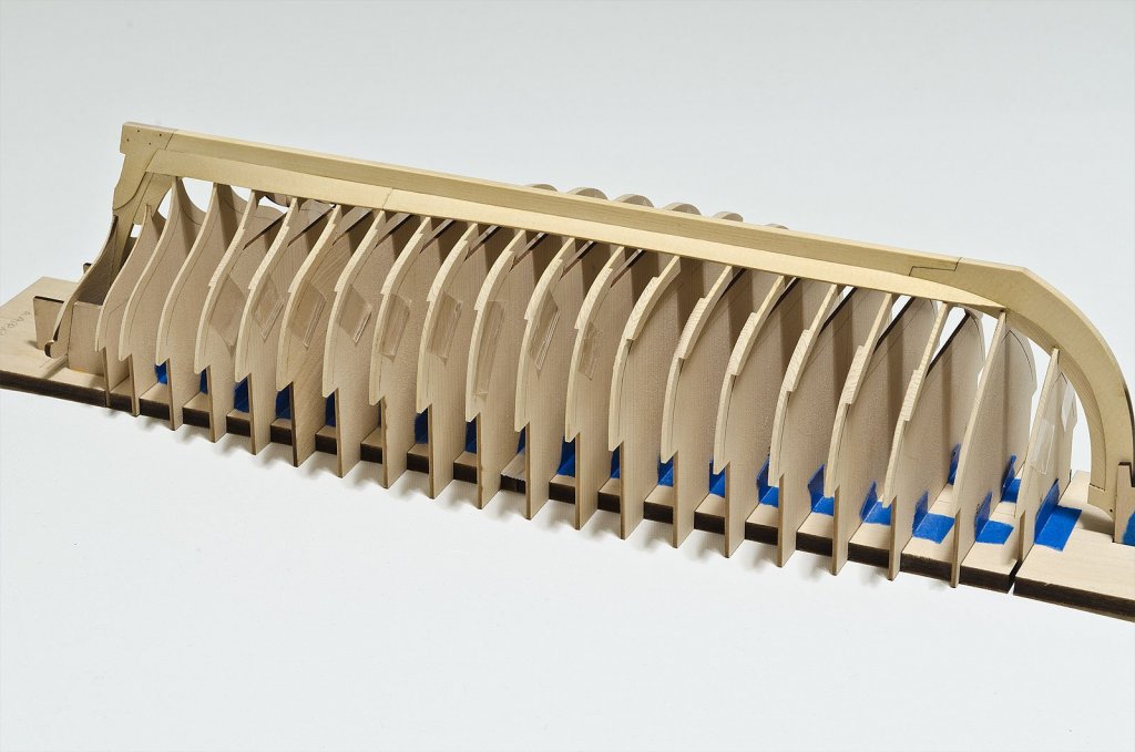
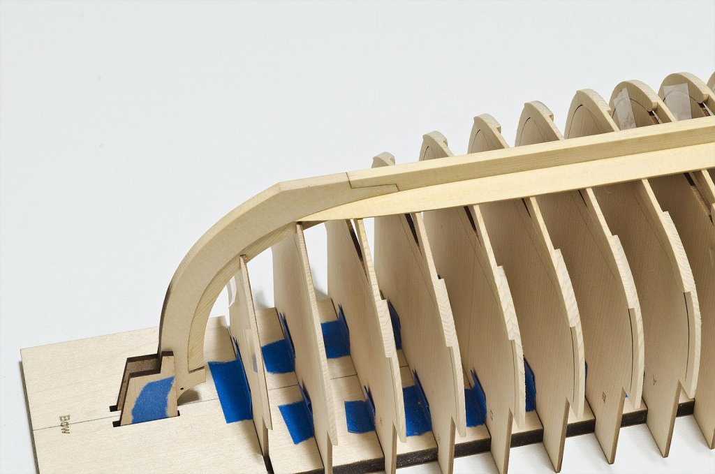
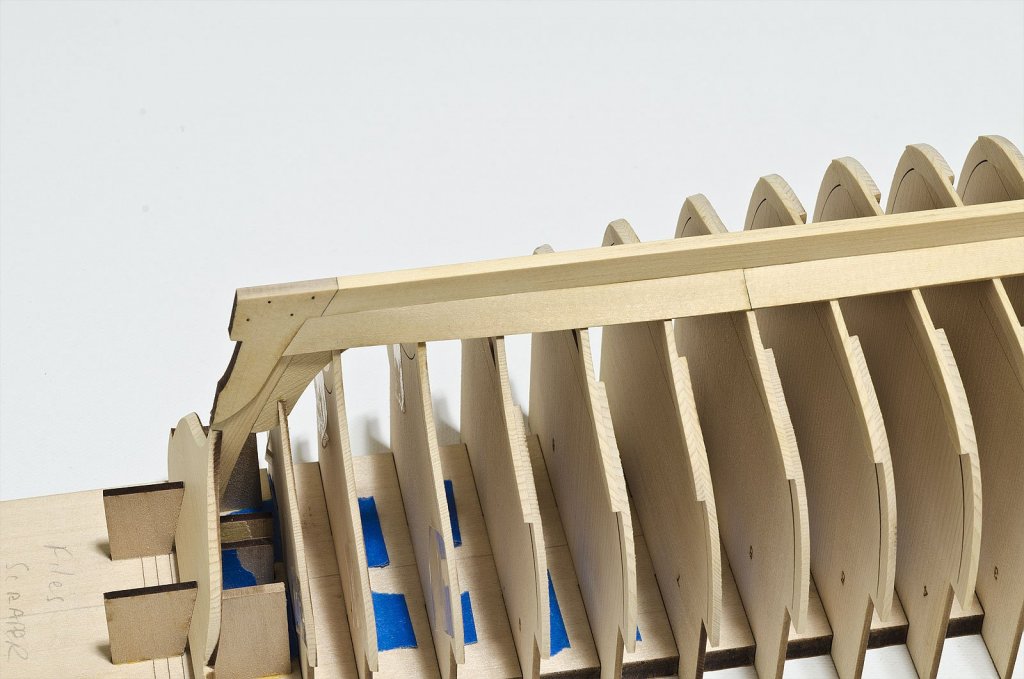
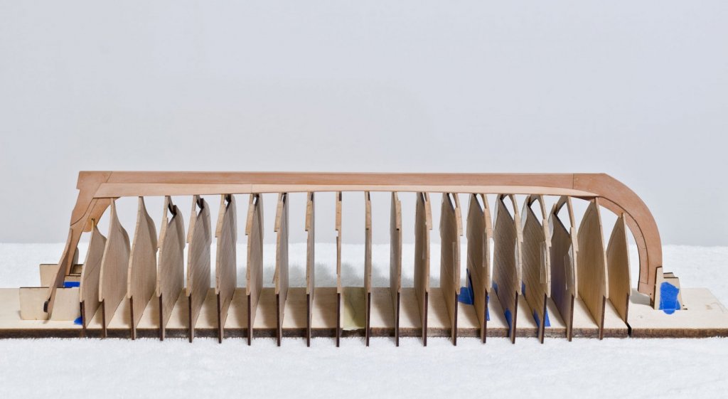
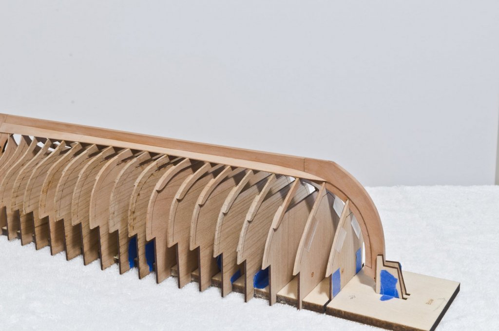
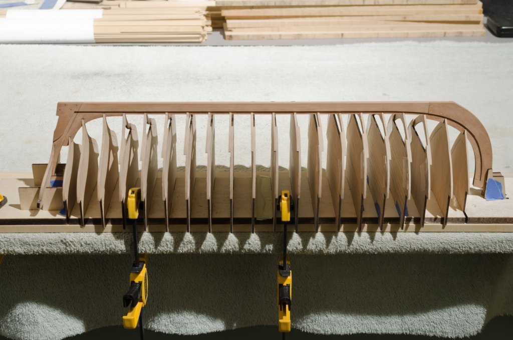
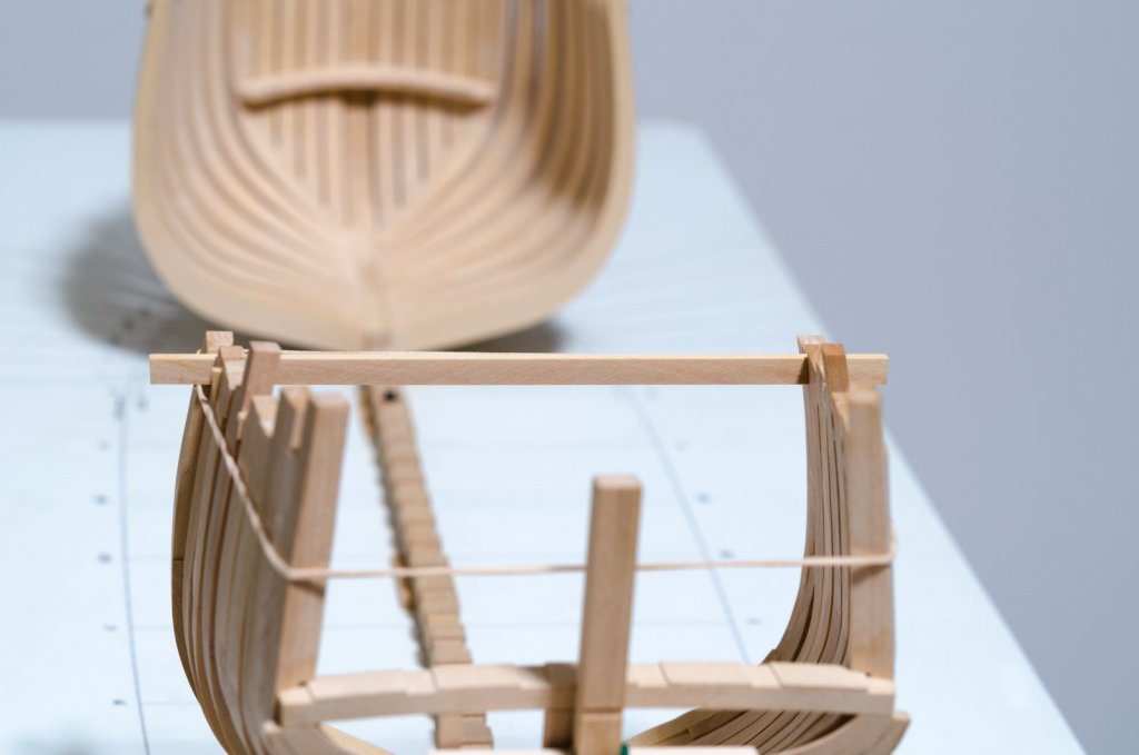
Welcome to my build log of Chuck's Medway Longboat. Shortly after starting his build log, Chuck asked me if I would consider building one out of Swiss Pear. The idea being that it might be of interest to other builders as an alternative to yellow cedar. I will be using all of the laser cut parts available. Also, I want to make note of anything that I have found that helped me to build it. Unfortunately, this log has been started a bit late in the project and few photos are provided as of now. I will take many more as I move ahead. I used a lap joint to attach the various components of the keel assembly. This was done on the mill. The frames were assembled and the keel attached as described by Chuck. Reinforced tape was used to hold the two sections of the build board together. I could see that the tape held the frames in position on the build board, so I added more tape in order to give this support to all the frames. This also flattens the bottom of the build board somewhat. I felt that the transom needed more support than an upright located inside, so I added one outside as well. This made the transom quite rigid. To secure the hull for fairing I clamped the build board down with a flat sheet of wood underneath to the edge of the work table. Between the tape and the clamping, the frames were held securely in preparation for fairing. One side has been faired. Clamped and ready for fairing. Mike


-
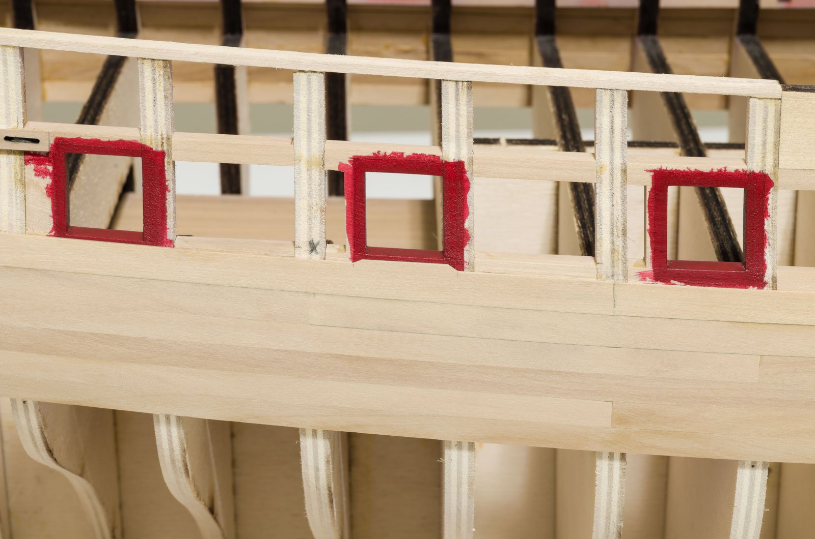
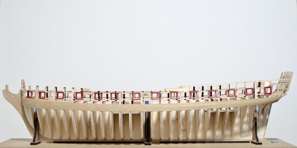
I have made some progress in the last month. The gun ports were spray painted using a mix of Windsor & Newton Crimson and Burnt Umber. The mix ratio is 10:1. I was surprised to see the color bleed into the soft ply so much, though It will all be covered after the planking is completed. Next, I made the bollard timbers. These proved to be quite a challenge along with some failed attempts. Most of the work was done on the disc sander and mill. The eight sided swivel mount and step were shaped with needle files. In preparation for the first layer wales I ran a batten which marks the lower wale location. As usual, Chuck made it easier with laser etched lines on each bulkhead. With the first batten in place a pencil line was drawn along its top edge onto each bulkhead. This line marks the bottom of the wales. Vertical measurements were made at each line and a corresponding mark was made to the other side of the hull. The result being that each side looked smooth and symmetrical with both battens in place. I completed the four strakes for the first layer of wales on both sides working from the bottom up. I did not adhere to the butt joint locations on this underlying layer as shown on the plans. I will on the second layer. Work was also started on the first of two layers that will make up the black strake. Mike
- 607 replies
-
- 30
-
-
- winchelsea
- Syren Ship Model Company
- (and 1 more)
-
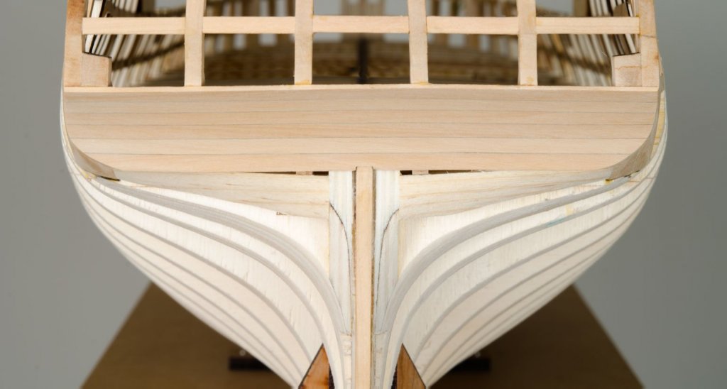
The lower counter has been planked and sanded. I used a #2b pencil to darken the plank edges. Decorative molding will cover the notch in the lowest plank. Mike
- 607 replies
-
- 33
-
-
- winchelsea
- Syren Ship Model Company
- (and 1 more)
-
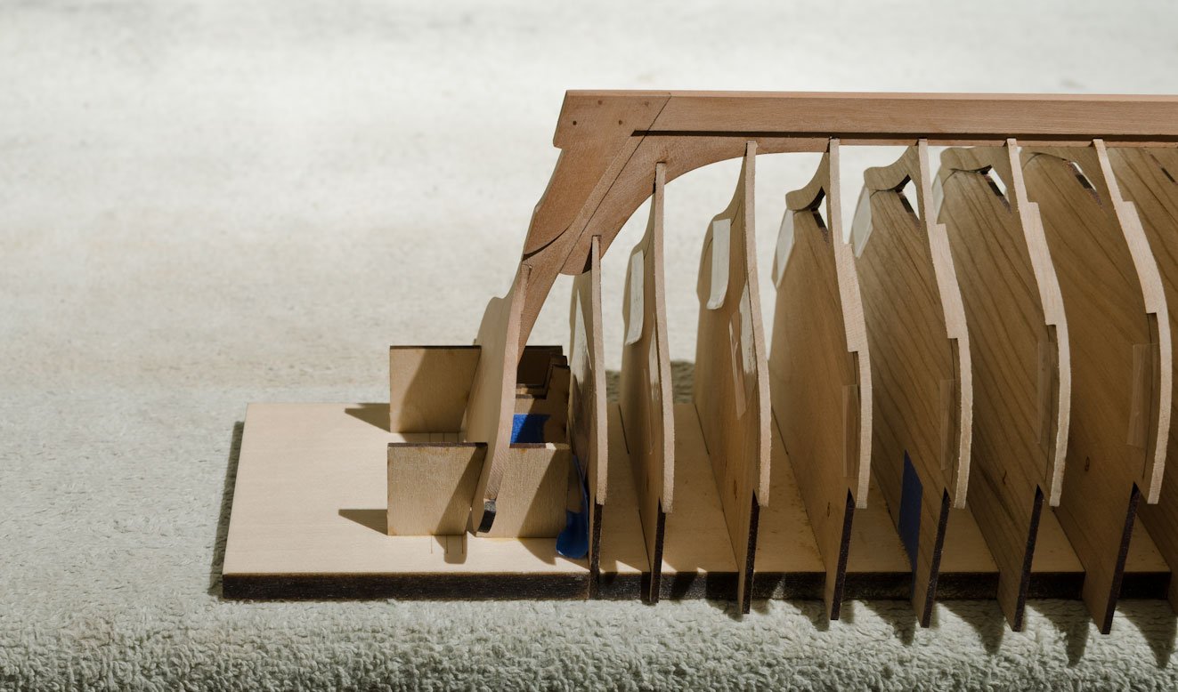
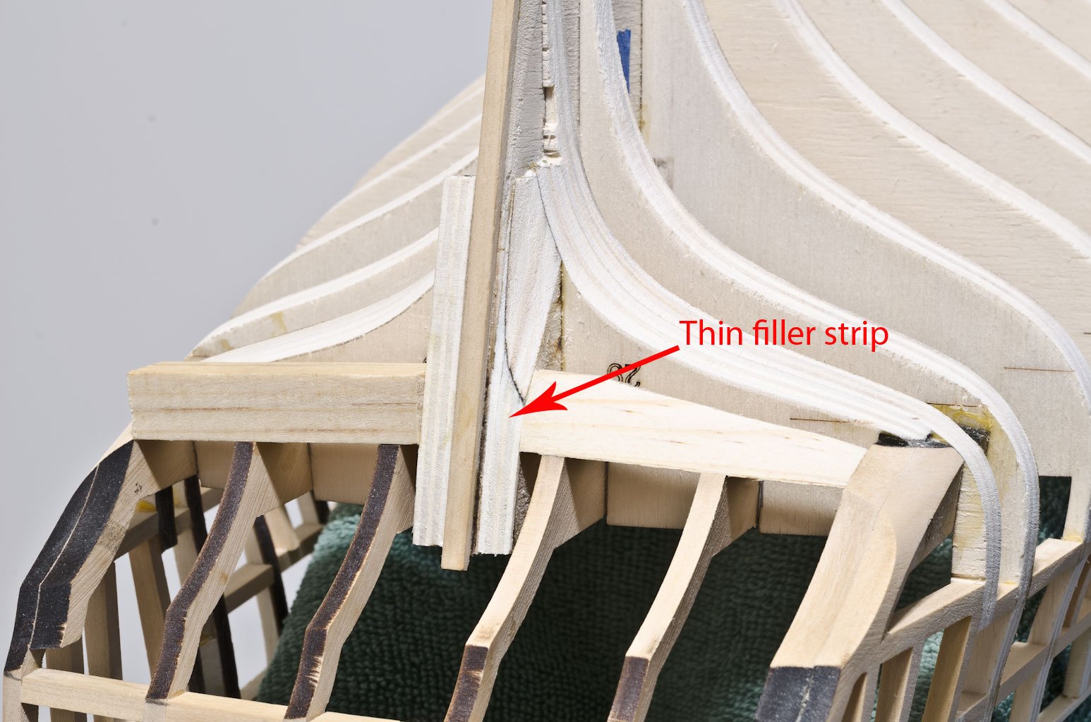
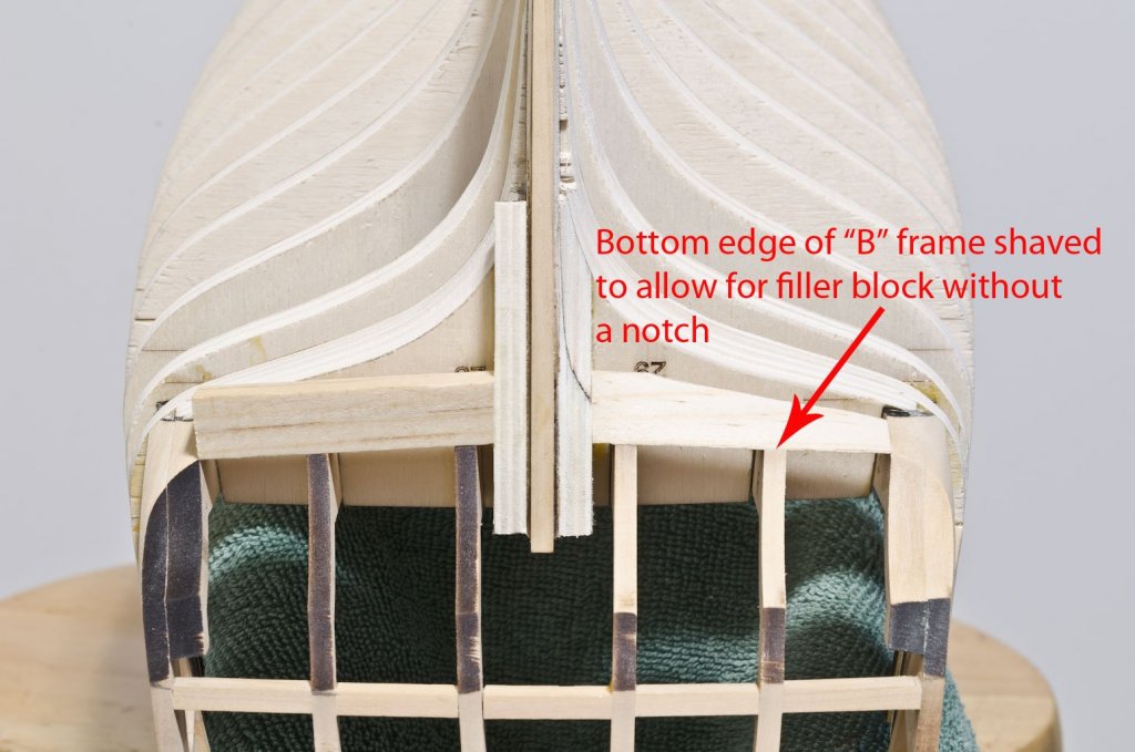
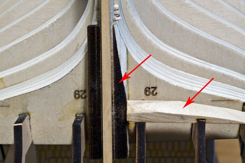
I've been working on the final fairing of the lower counter. It was determined that the vertical filler piece was not close enough to the rabbet strip, so a thin strip was added to the aft edge of the filler piece. The first horizontal filler block had a score where the "B" frame was located. I removed the block and shaved the bottom edge of the "B" frame down, level with the other frames. The new block now sits neatly across the frames. I left one side not yet faired to show how much wood was removed to fair this area. The transition between the two filler pieces becomes clear as more and more wood is removed. A batten strip was used in various locations to make sure that enough wood was removed. Mike

- 607 replies
-
- 21
-
-
- winchelsea
- Syren Ship Model Company
- (and 1 more)
-
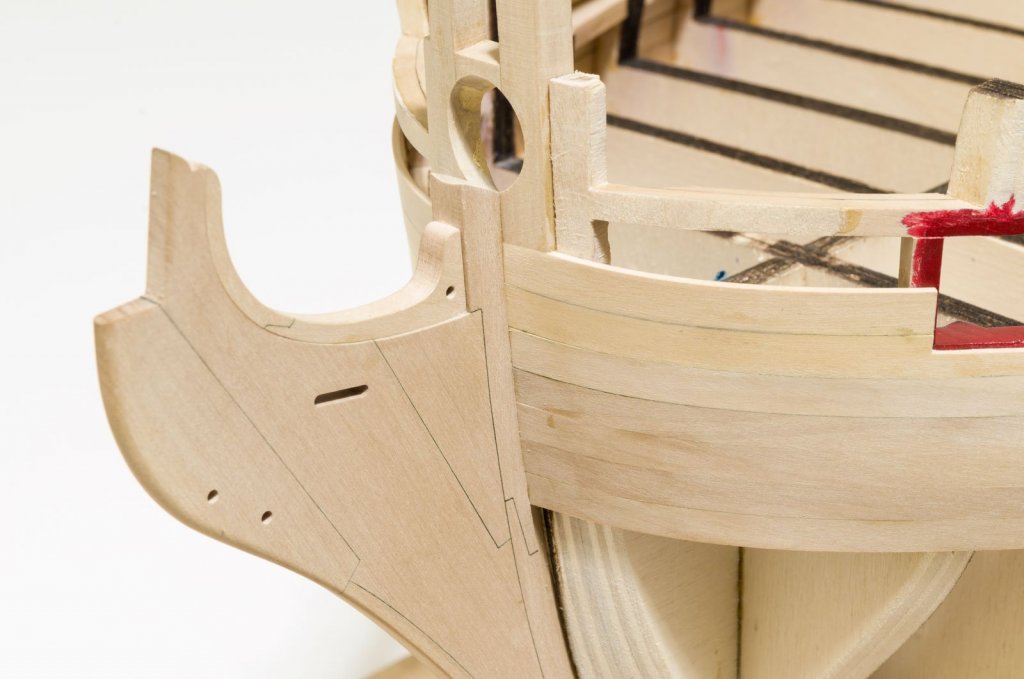
Joe, I am working closely with Chuck on this build, but it is not a true beta build in the way you are suggesting. There will be times when I do scratch over laser cut. Not to make it better, but to work on my scratch building skills. The nine piece knee of the head was scratched since there was concern about laser cutting 1/4" boxwood. The fixed blocks were milled. For the kit version, these parts will most likely be laser cut, though perhaps not in boxwood. Mike
- 607 replies
-
- 7
-
-
- winchelsea
- Syren Ship Model Company
- (and 1 more)
-
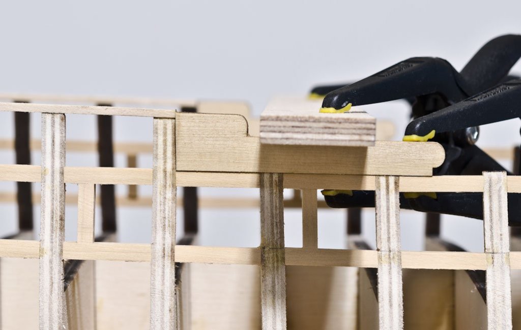
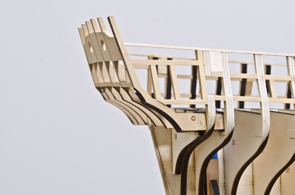
Thank you, Harley! I probably used the word "cross-spall" loosely in that post. I used a flat piece of wood clamped across the top of the hance pieces to make sure that the top edge was flat across the hull. On Hayling, I used a cross-spall or batten strip to insure that the frames were parallel across their tops. I tack glued the strip at the height of the top timbers. I set the frame when both sides were the same in vertical measurement to the top of the batten. There are other ways to do this when using a cross-spall, but I found that this way worked for me. Mike
- 607 replies
-
- 15
-
-
- winchelsea
- Syren Ship Model Company
- (and 1 more)
-
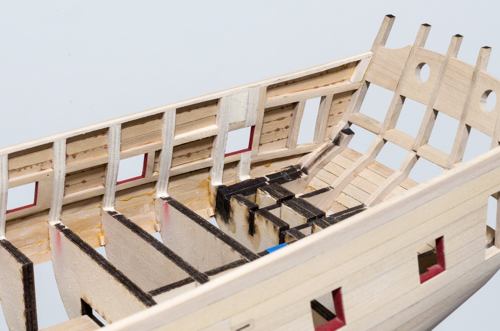
I've been working on a few things over the past week. The quarter gallery framing and surrounding area was faired some more. The tops of the two outer stern frames were reduced in thickness from 1/4" to 5/32" in order to match the thickness of the inner frames. The entire area was then faired to establish a smooth batten run down the hull. You can see how much material has been removed compared to the photo above from an earlier post. Next, the entire hull was faired with the exception of the two filler pieces under the lower counter. I started on them, but remain unsure about the transition from one to the other. Hopefully, this will become less confusing after I talk to Chuck this week. I did manage to add the fixed blocks. 1/32" Slots were milled for each of these. I did not mill the slots on a strip of wood that was the exact width required. Rather, I used a much wider strip. The advantage being that it was not necessary to mill the slot to the exact angle and position on the strip. Paper templates were cut from the plan drawing and the slots carefully removed with a #11 blade. They were then aligned over the milled slots and adhered with Elmer's School Glue. With the template as a guide, the outer edges of each block was sanded down on the disc sander to the proper width all around. The sheaves were made from slivers of wood cut from discs of the same thickness as the slot. Each sheave is thinner than the actual block, so they can recess slightly into the block. A #2 pencil was used to darken the sheave slot and the actual sheave. Mike


- 607 replies
-
- 29
-
-
- winchelsea
- Syren Ship Model Company
- (and 1 more)
-
Joe, I use a Nikon D5100 on a tripod. I chose this camera for its low price yet it has a really good 16 mega-pixel sensor. I only use prime lenses. Zoom lenses are okay, just not as sharp. Closeup I use the Nikon AF-S Micro NIKKOR 60mm f/2.8G ED Lens. Further away I use the Nikon AF-S DX NIKKOR 35mm f/1.8G Lens Mike
- 450 replies
-
- 3
-
-
- cheerful
- Syren Ship Model Company
- (and 1 more)
-
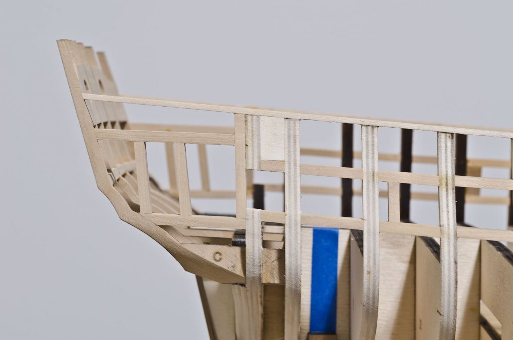
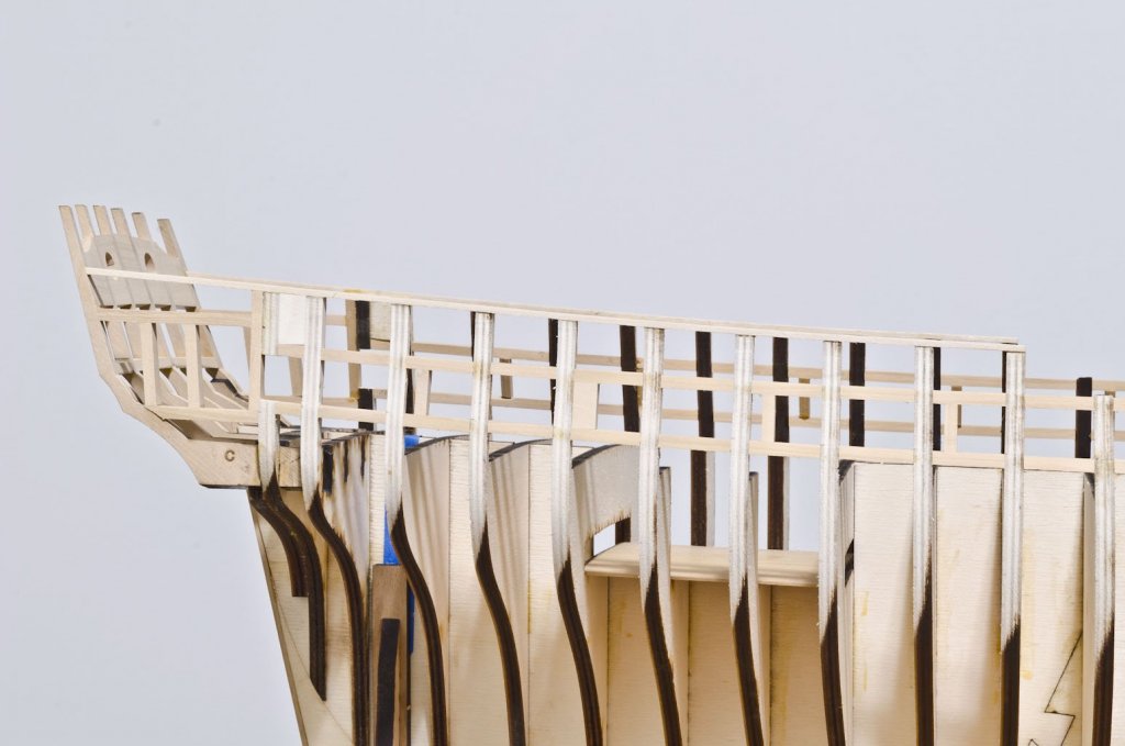
The four hance pieces are in. They were laser cut from yellow cedar and set proud in order to shape them to the outboard hull shape. A cross spall was used to insure that they sit straight. Mike
- 607 replies
-
- 25
-
-
- winchelsea
- Syren Ship Model Company
- (and 1 more)
-
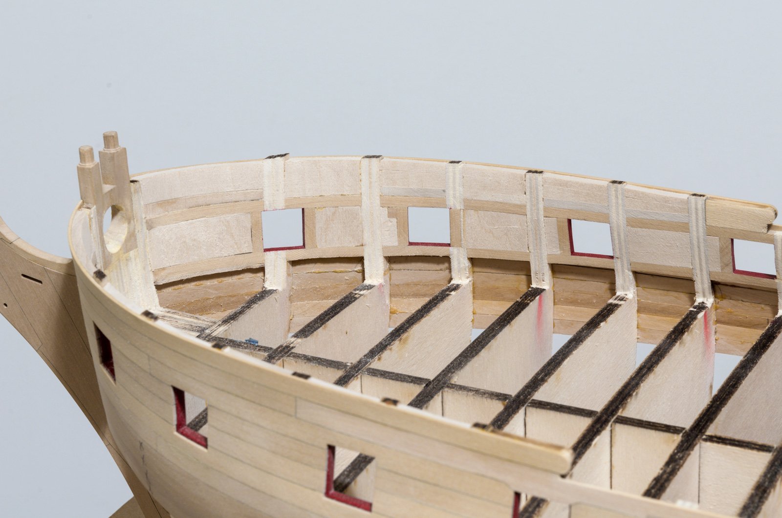
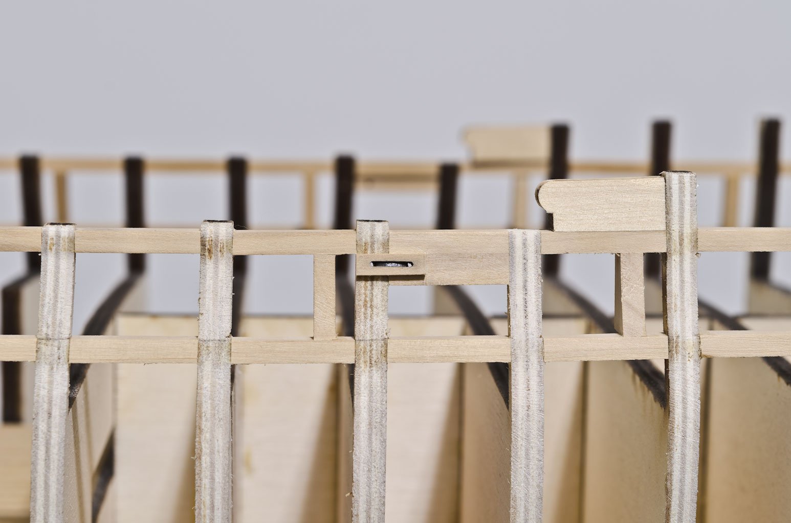
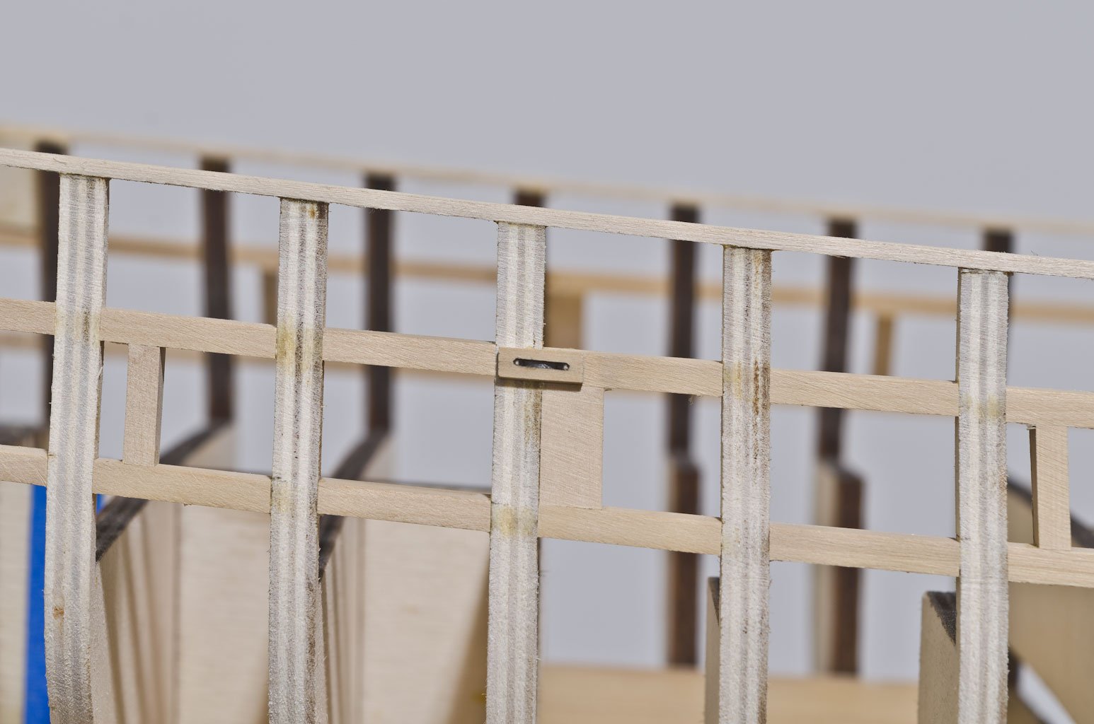
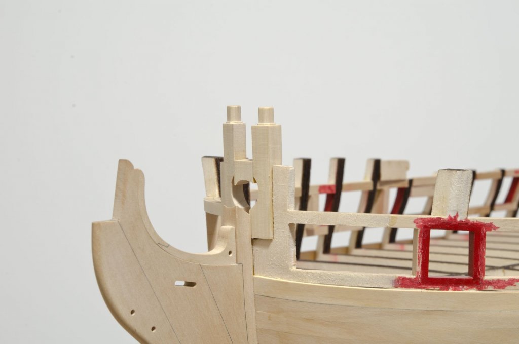
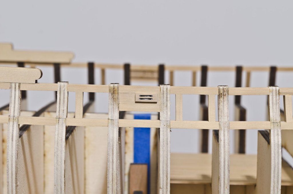
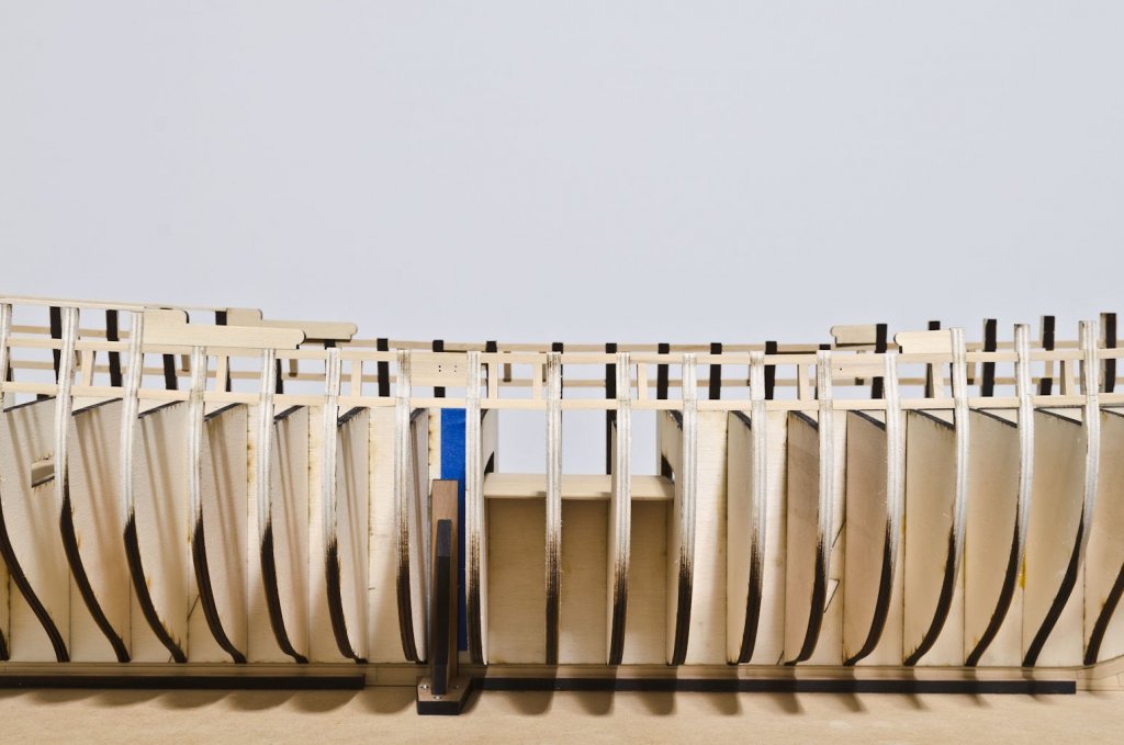
Thank You, Maury and for all the "Likes"! The quarter gallery framing and aft-most gun port turned out to be my week's project. The 5/64" X 1/4" strip along the top of the quarter deck bulkheads was made from basswood. I sanded the bulkhead tops to the correct angles for a smooth flow of the strip. Getting the symmetry from one side to the other took patience and repeated eyeballing. The framing of the quarter gallery required a bit of experimentation. There are a number of angles on each strip and no two strips are the same, except for the two gallery entrance strips. Rather than waste precious boxwood, I used basswood strips to find the correct angles. As an example, one strip had angles of 70° and 10° on one side, 6.5° and 5° on the other. A disc sander with multiple adjustments comes in handy. After completing the horizontal strips I made the two aft-most gun ports. Lastly, the quarter gallery entrance strips were added. The plan detail proved to be very useful for getting exact measurements. All strips were inserted standing proud, allowing for shaping to the hull shape when fairing. I faired the work leaving a wee bit more for later on when I start work on the lower hull. I'm always trying to stay one step back until I'm sure of where I'm going. Mike
- 607 replies
-
- 27
-
-
- winchelsea
- Syren Ship Model Company
- (and 1 more)