HOLIDAY DONATION DRIVE - SUPPORT MSW - DO YOUR PART TO KEEP THIS GREAT FORUM GOING! (89 donations so far out of 49,000 members - C'mon guys!)
×


Stuntflyer
-
Posts
1,197 -
Joined
-
Last visited
Content Type
Profiles
Forums
Gallery
Events
Everything posted by Stuntflyer
-
 Thanks for the comments and "Likes"! Chris, I would be interested in knowing what alternative finishes you are referring to. Mike
- 607 replies
-
- 3
-

-
- winchelsea
- Syren Ship Model Company
- (and 1 more)
-
Well, Steve, I certainly wouldn't discourage anyone from using Cherry. Of course, one would get all those great mini-kits from Chuck too. Mike
- 607 replies
-
- 5
-
-
- winchelsea
- Syren Ship Model Company
- (and 1 more)
-
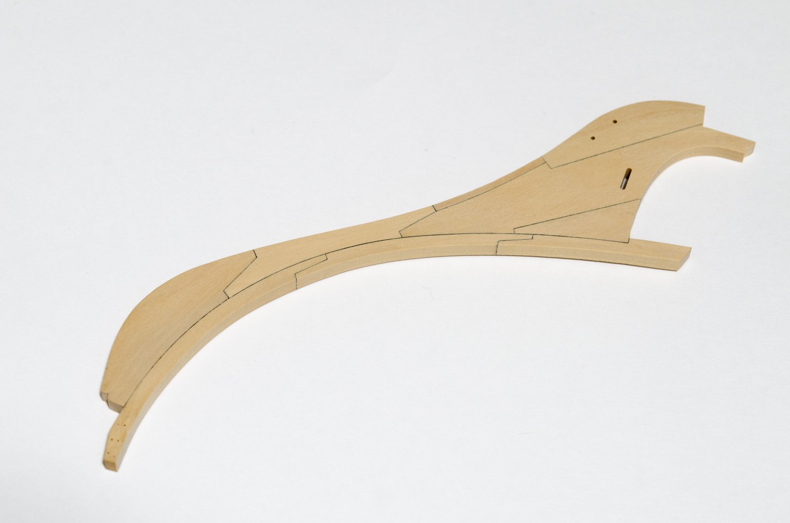
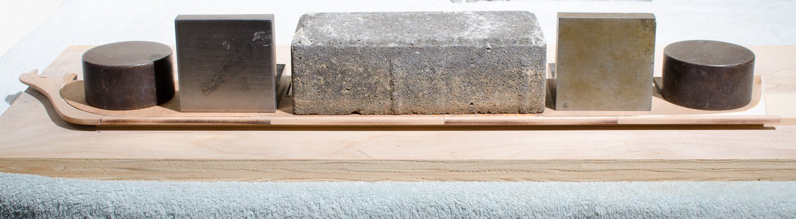
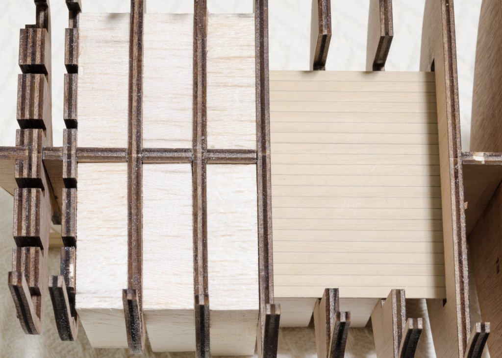
Hello everyone! Since my last post I have been contemplating whether or not my using Cherry as the primary wood was the right choice for me. No doubt some beautiful ships have been built from Cherry, but I really prefer the look of boxwood. I thought about removing just the knee and keel assembly, but quickly ruled that out. The problem being that it would be difficult aligning those new parts to the already assembled bulkhead former/bulkhead assembly. This meant that I would have to start over from the beginning. So, over the last few weeks I have managed to re-build her with boxwood. Right now, 3/16" laser cut boxwood kits are not being offered for the Winnie. The nine pieces making up the knee parts were scratched from 3/16" boxwood sheet. The mill came in handy for making the bobstay holes and gammon slot. I'm going with copper bolts this time. Blackening will be done later. Large blocks were used to handle any slight twists in the bulkheads while at the same time keeping the structure straight. The two lower platforms were added as well. Mike


- 607 replies
-
- 35
-
-
- winchelsea
- Syren Ship Model Company
- (and 1 more)
-
Made a bit more progress today by simulating the lower stem and keel bolts. Holes were drilled with a #76 bit and filled with .017 black monofilament and PVA glue. I'm not a big fan of CA as it has a tendency to discolor the wood. I anxious to see what the Cherry will look like after a coat of W-O-P. I should know soon enough. Mike
- 607 replies
-
- 28
-
-
- winchelsea
- Syren Ship Model Company
- (and 1 more)
-
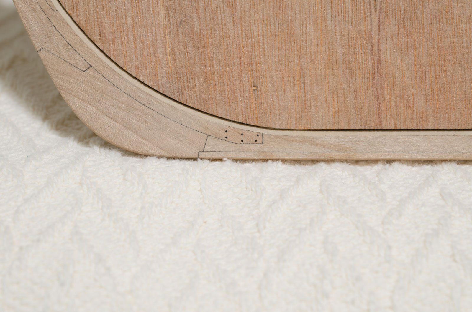
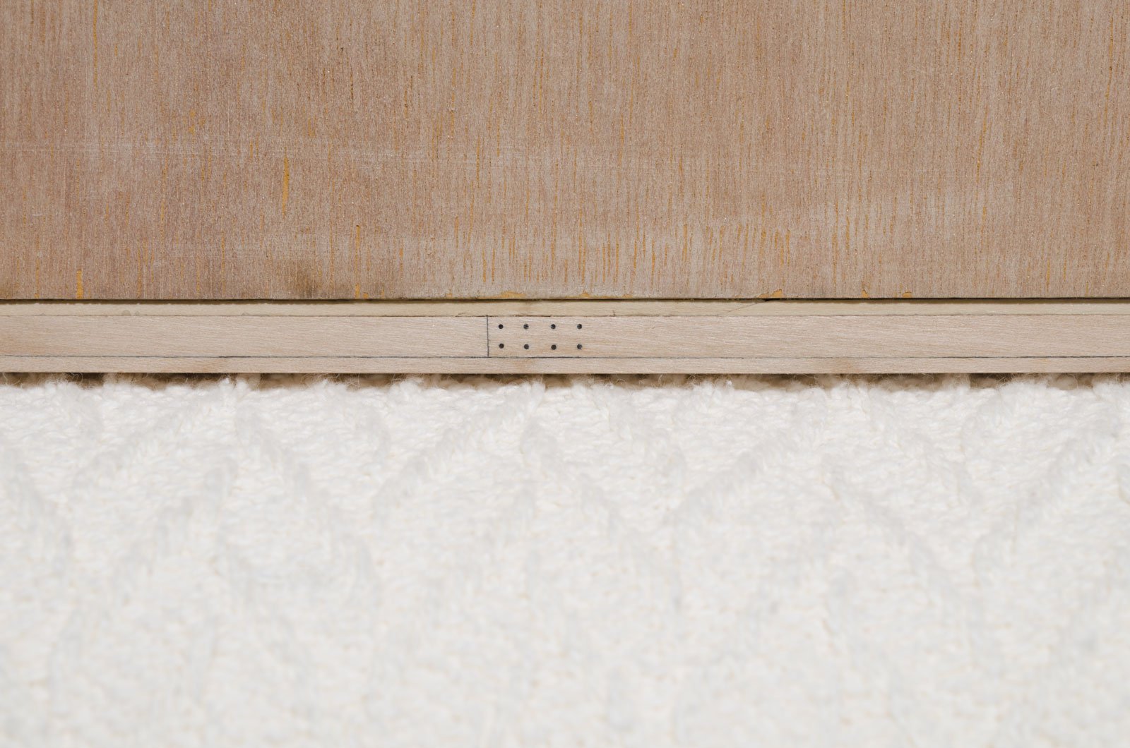
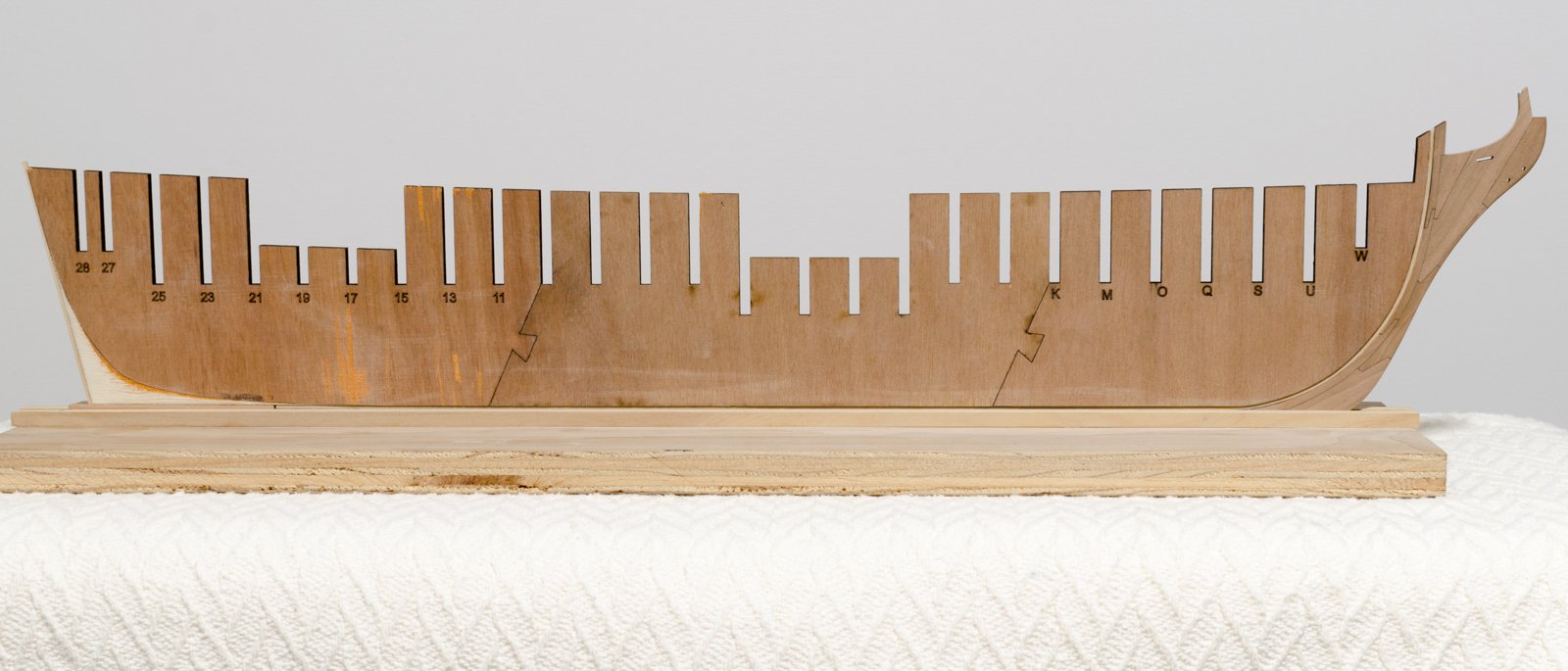
In preparation for making the false keel, the keel bottom was sanded 90° to its adjacent edge and smooth across its bottom face. To do this, I first raised the bulkhead former/keel assembly off the flat surface with 1/4" flat sheet. I used a square sanding block, gliding along the flat surface of the board to sand the edge. The false keel was ripped on the table saw from some scrap Cheery that I had lying around. It's made in three sections joined with what I think is called a "Harris joint". As you can see, I located the joint far enough away from the keel joint. In preparation for adding the bulkheads I made the build board that will hold everything upright and straight. Mike


- 607 replies
-
- 24
-
-
- winchelsea
- Syren Ship Model Company
- (and 1 more)
-
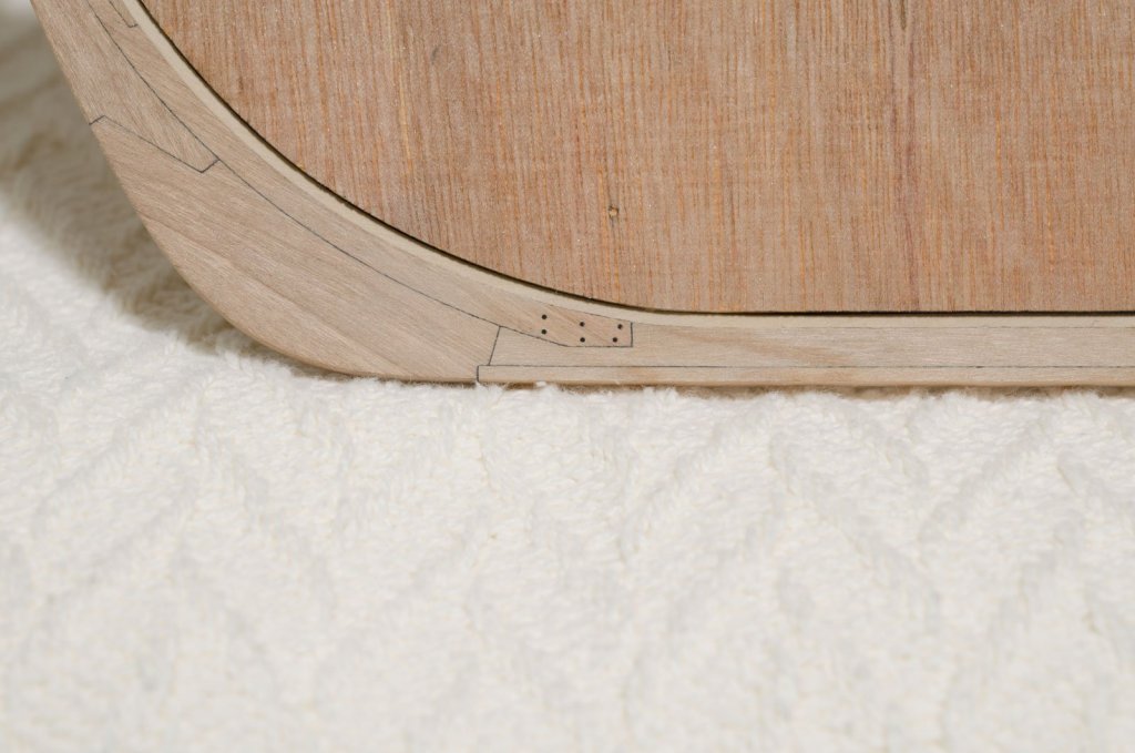
I Added knee assembly to the bulkhead former. Some shaping was necessary in order to get a nice fit around the rabbet. Next I added the four section keel. You should be able to see where I removed a short section of the rabbet to accommodate the aft most keel section. Mike

- 607 replies
-
- 22
-
-
- winchelsea
- Syren Ship Model Company
- (and 1 more)
-
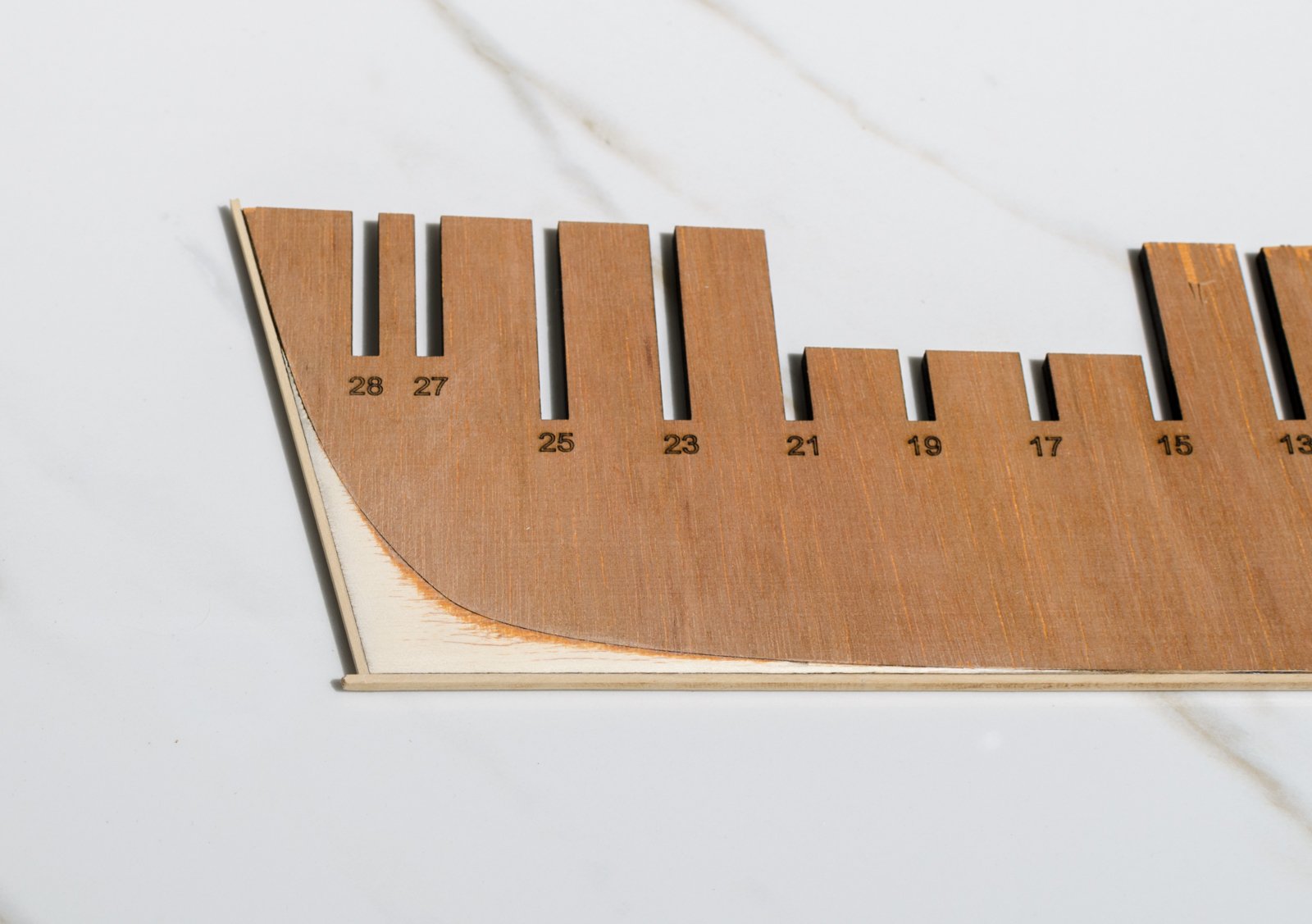
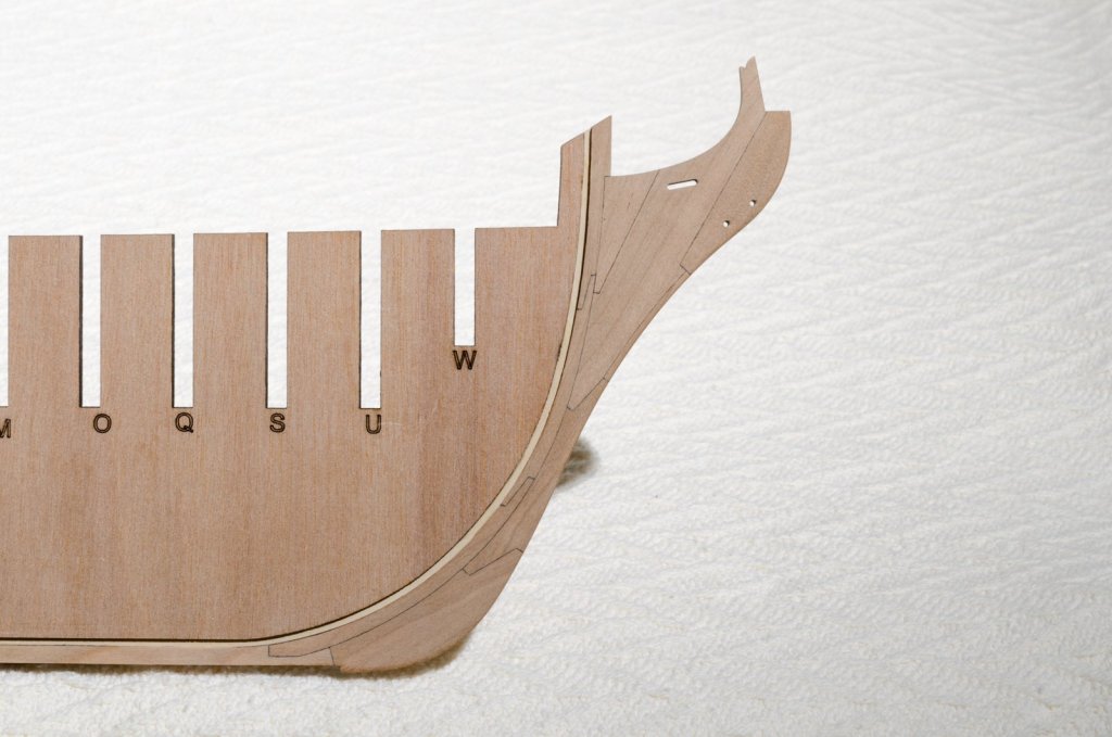
I managed to complete the bearding line today. The wood is easy to work with, using just a coarse file and some medium grit sandpaper. The rabbet will be shortened as Chuck described above when I attach the aft section of the four section keel. Mike

- 607 replies
-
- 16
-
-
- winchelsea
- Syren Ship Model Company
- (and 1 more)
-
Yup! Got it. I will use the the additional length to guide me while shaping the bearding line and then remove it afterwards. Mike
- 607 replies
-
- 10
-
-
- winchelsea
- Syren Ship Model Company
- (and 1 more)
-
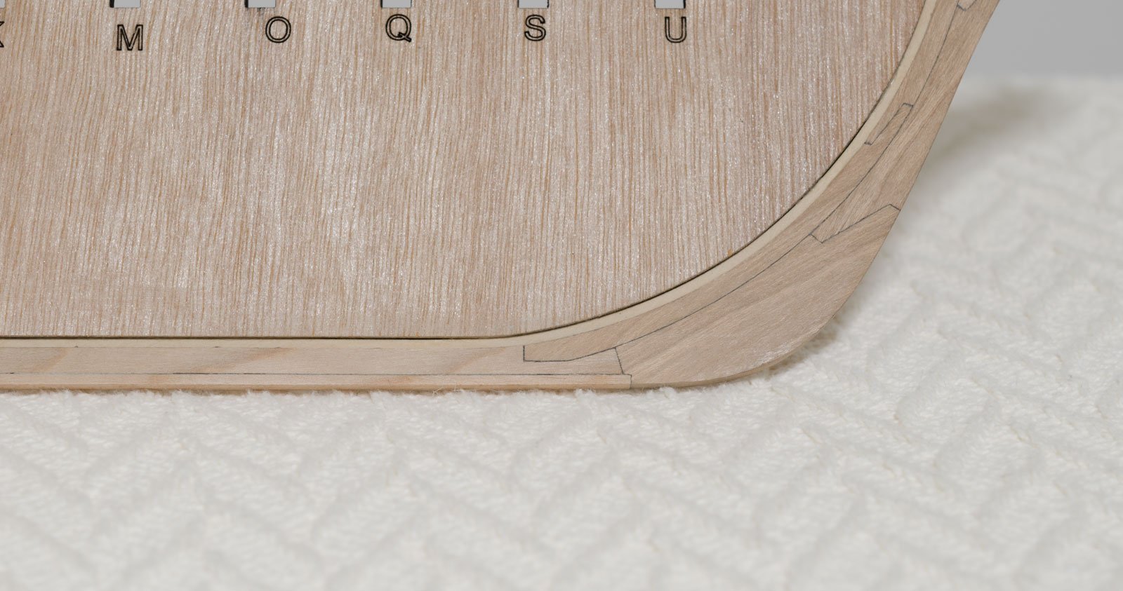
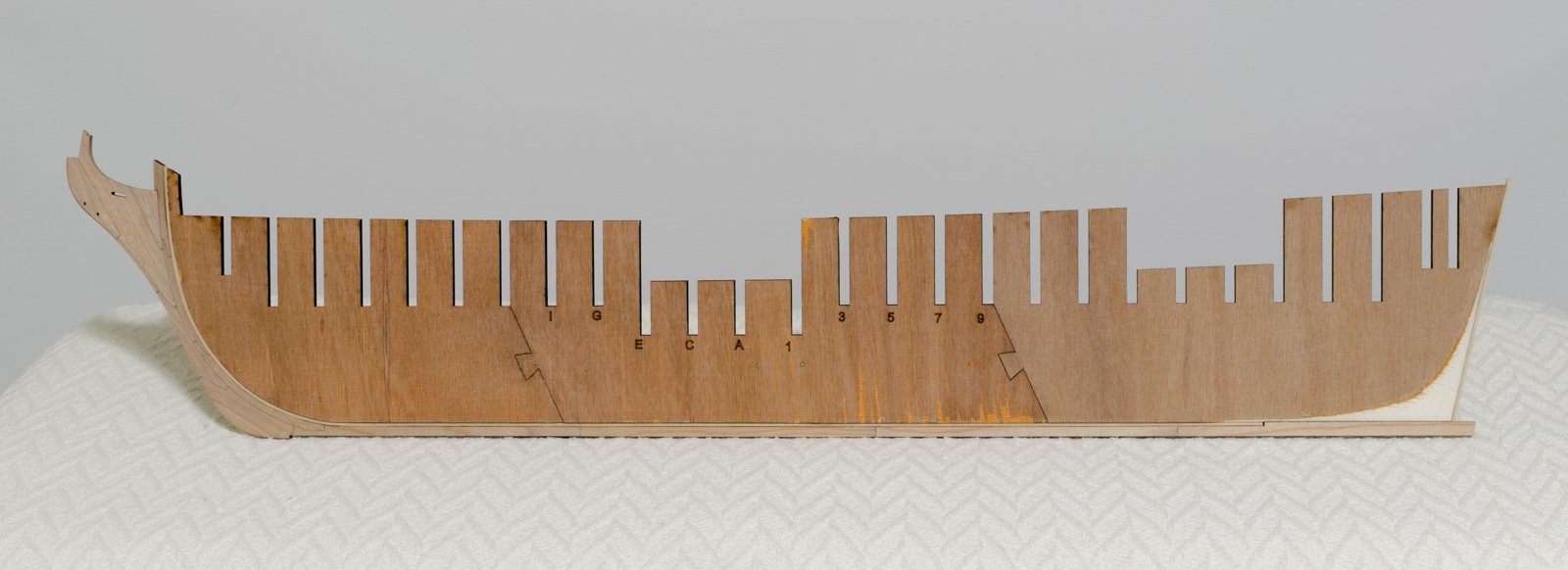
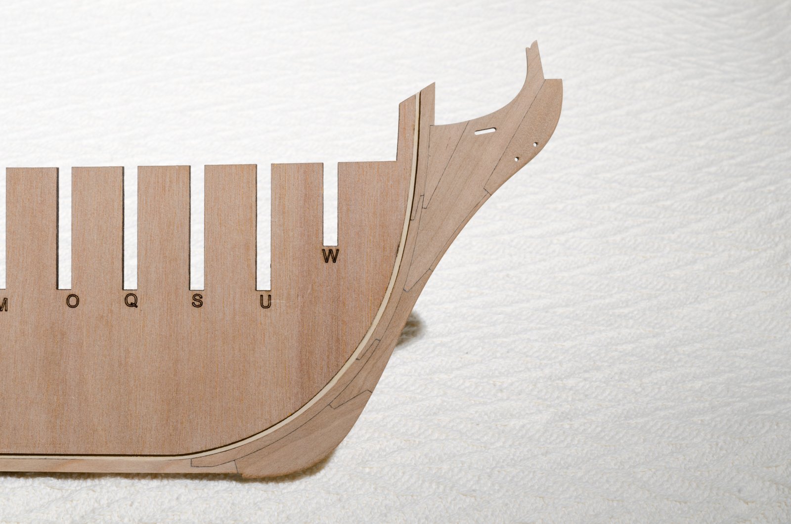
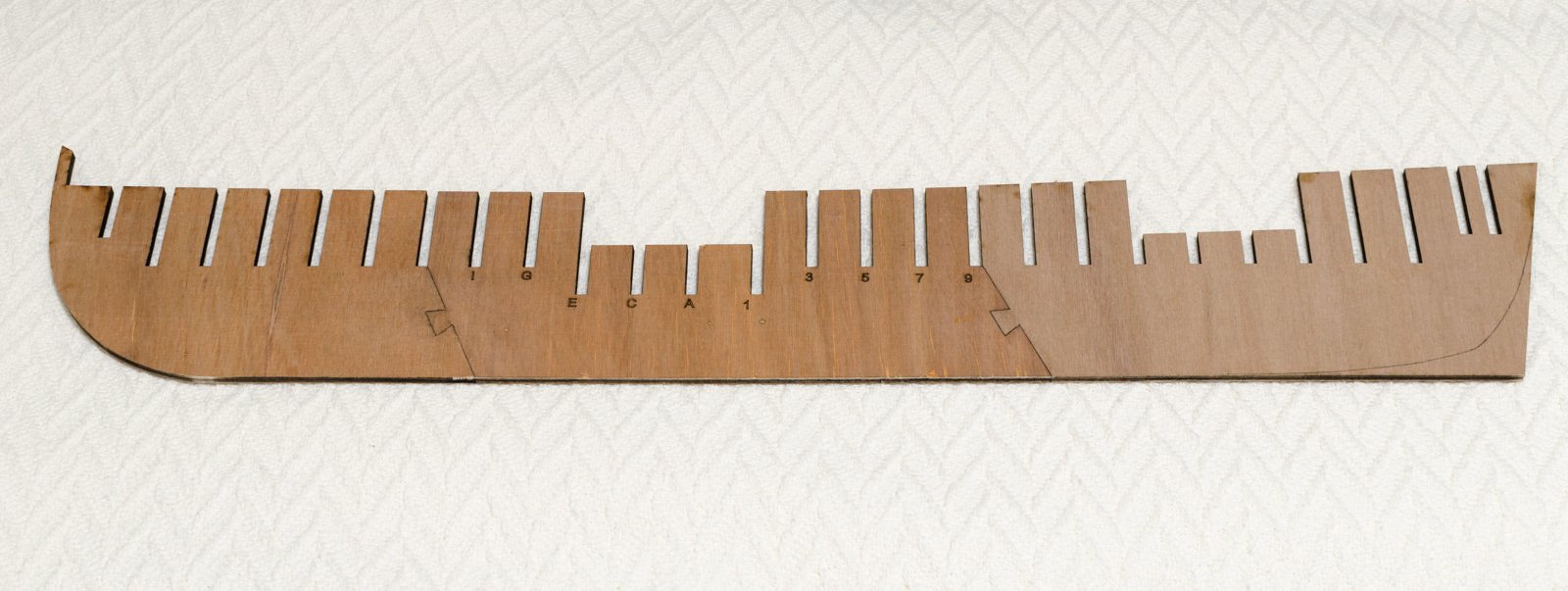
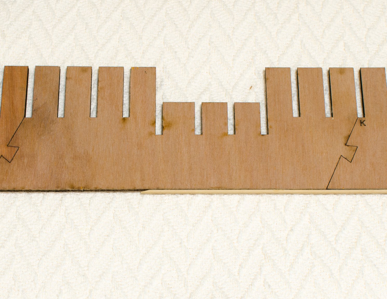
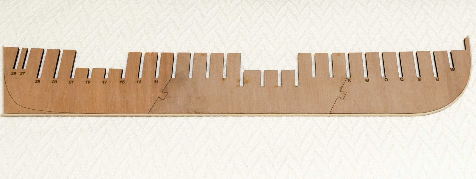
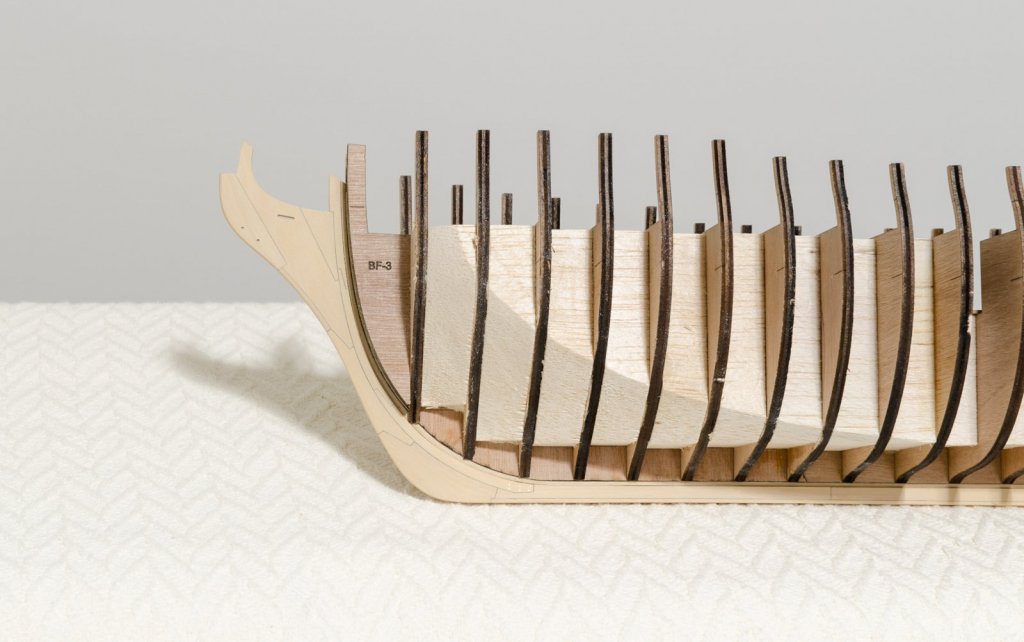
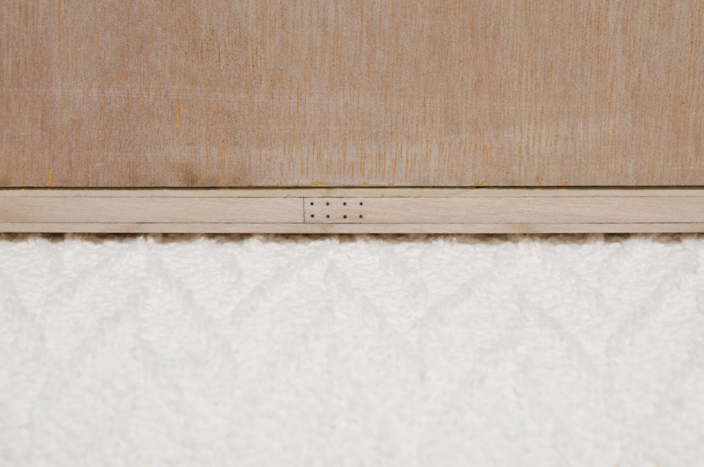
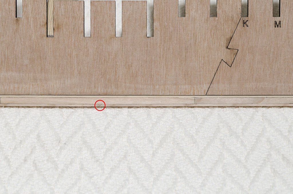
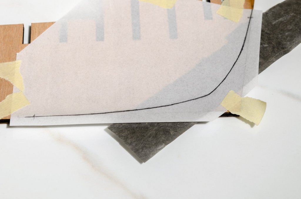
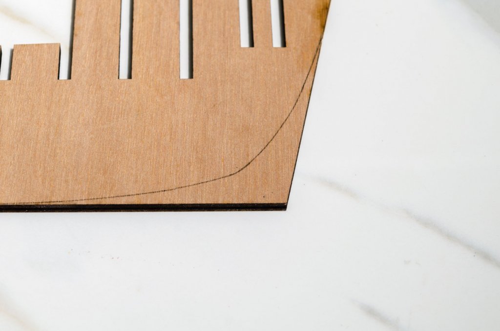
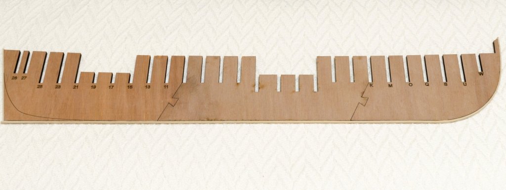
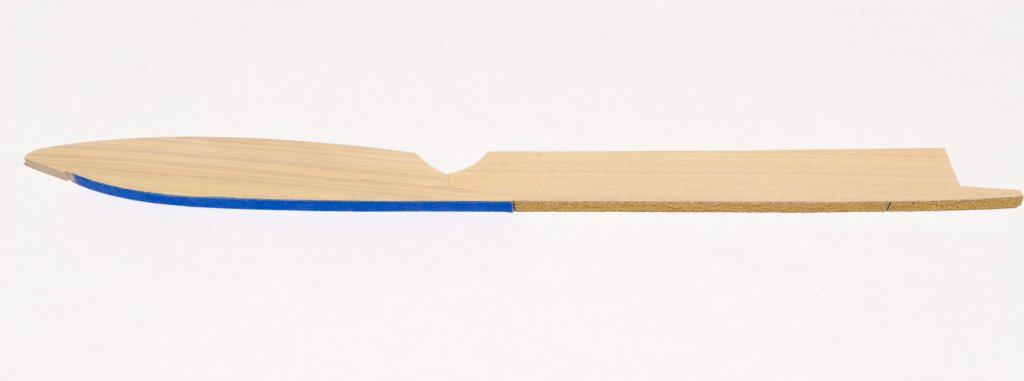
Snowy nights are a perfect time to get back into the workshop. The bulkhead former is now in one piece. These laser cut parts were joined with Elmer's Carpenter glue without any prior sanding on the joints. A slab of flat marble was used to rest the parts on while the glue set. The bearding line is laser etched into one side of the former. I traced the line and transferred its shape to the other side using graphite paper. The rabbet is 1/16" x 3/32" strip which was cut from 3/32" boxwood sheet. The fore side was moistened and heat bent into shape with a blow dryer. Since the former is rather long the rabbet strip was made in two pieces joined with an angle joint for strength. This joint also makes it easy to align the next section, simply by slipping it under the first section. The completed rabbet with a small section also added to the aft area of the former. Mike


- 607 replies
-
- 18
-
-
- winchelsea
- Syren Ship Model Company
- (and 1 more)
-
Nicely done, Bob! Looking forward to your next build, as always. Mike
- 682 replies
-
- 4
-
-
- halifax
- lumberyard
- (and 1 more)
-
Thanks guys for the kind words and for all the "Likes". Right now I'm trying to decide whether to fair the exterior hull or continue making deck clamps. Mike
-
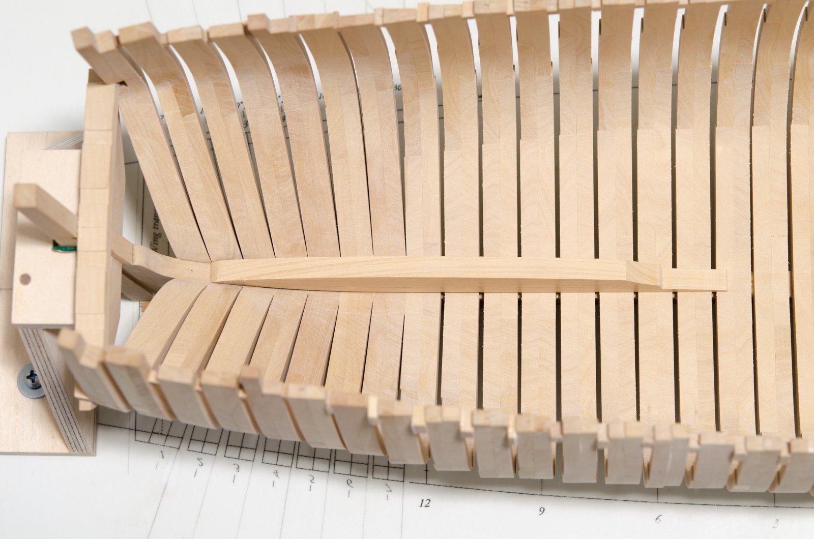
With the upper deck clamps completed I was able to install the keelson. Lengths of pine were pushed down by strips that I passed athwartships through the spaces between the frames, thus holding the keelson down tight to the floor timbers while the glue sets. With the keelson in place bolts were inserted and peened down tight into the floors timbers. Mike

-
Beautiful work, druxey! I know how much research went into the ship's rigging and other details. Good luck with the forthcoming book. Mike
-
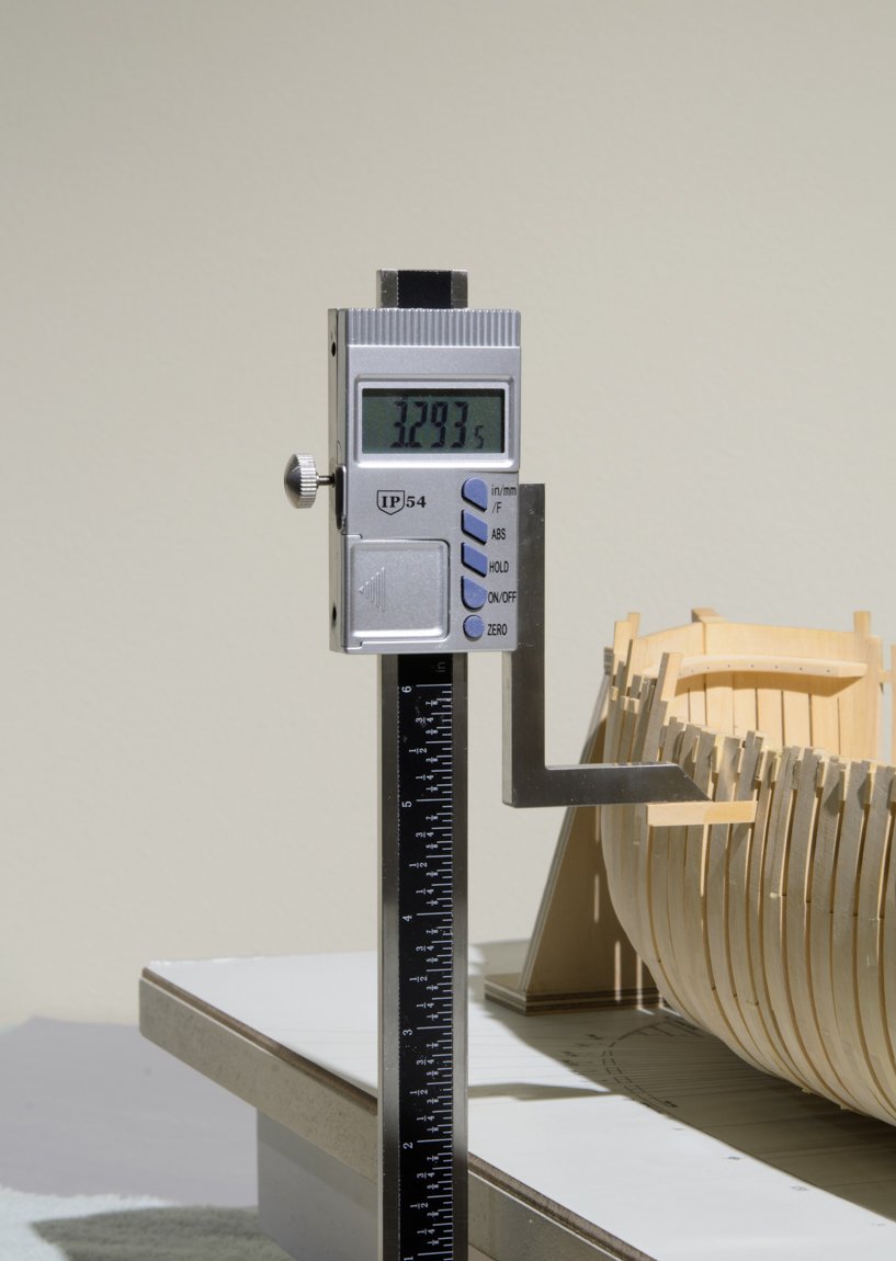
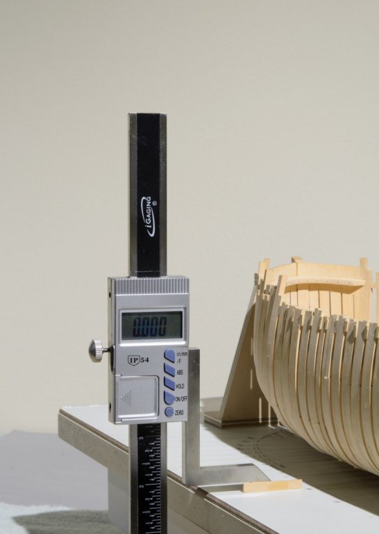
Kurt, you can find it here . . https://www.ebay.com/sch/i.html?_from=R40&_trksid=p2057872.m570.l1313.TR0.TRC0.H0.XiGaging+Digital+Electronic+Height+Gauge+with+Magnetic+Base%2C+6+Inch.TRS5&_nkw=iGaging+Digital+Electronic+Height+Gauge+with+Magnetic+Base%2C+6+Inch&_sacat=0
-
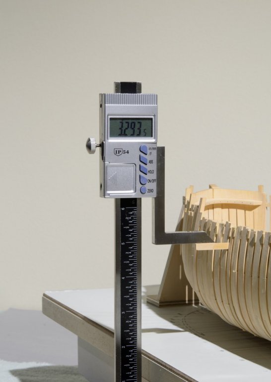
The keelson has all three sections joined and sanded to shape, though not glued to the frames yet. I will need to drill holes for the bolts which will go through each floor timber and install the two upper deck clamps first. The upper deck clamp is 4" thick (.083 actual). It is made in three sections joined by two scarph joints. The fore section had to be steam bent into shape. The other two sections were shaped with dry heat. The height of the clamp was carefully measured at several stations (frame locations) on the draught. Those measurements along with adjustments necessary to account for the beam heights were then transferred to the frames with the aid of a height gauge. I attached a piece of strip wood to the gauge that was thin enough to fit between the frames. Looking at the these photos, it appears that the clamp is sloping downward as it turns inward near the transom. Before going into panic mode I decided to check this out for myself. I placed a batten along the top edge of the clamp while eyeing it from the rear of the ship. Turns out it's just an optical illusion. With the port side completed these frames are now quite strong compared to before. Mike
-
Hi Tom, Here is the information you were looking for. I use both the "0" and "2" cut. Mostly the "0". The tip is 8mm wide. http://www.ottofrei.com/Riffler-File-Hand-LR12711 Mike
-
Happy New Year Ken, I did a re-write of the post which I'm hoping will make things a bit clearer. Mike
-
druxey: Some of those steps in the floors are more than slight. I don't mind the extra sanding if it insures that the frames are not cut too thin to begin with. Kurt: A lot of these frames have glue squeezed out. I disc sanded one frame smooth and almost took off too much wood. So, I kinda gave up on that idea. Besides, I love sanding wood! Mike
-
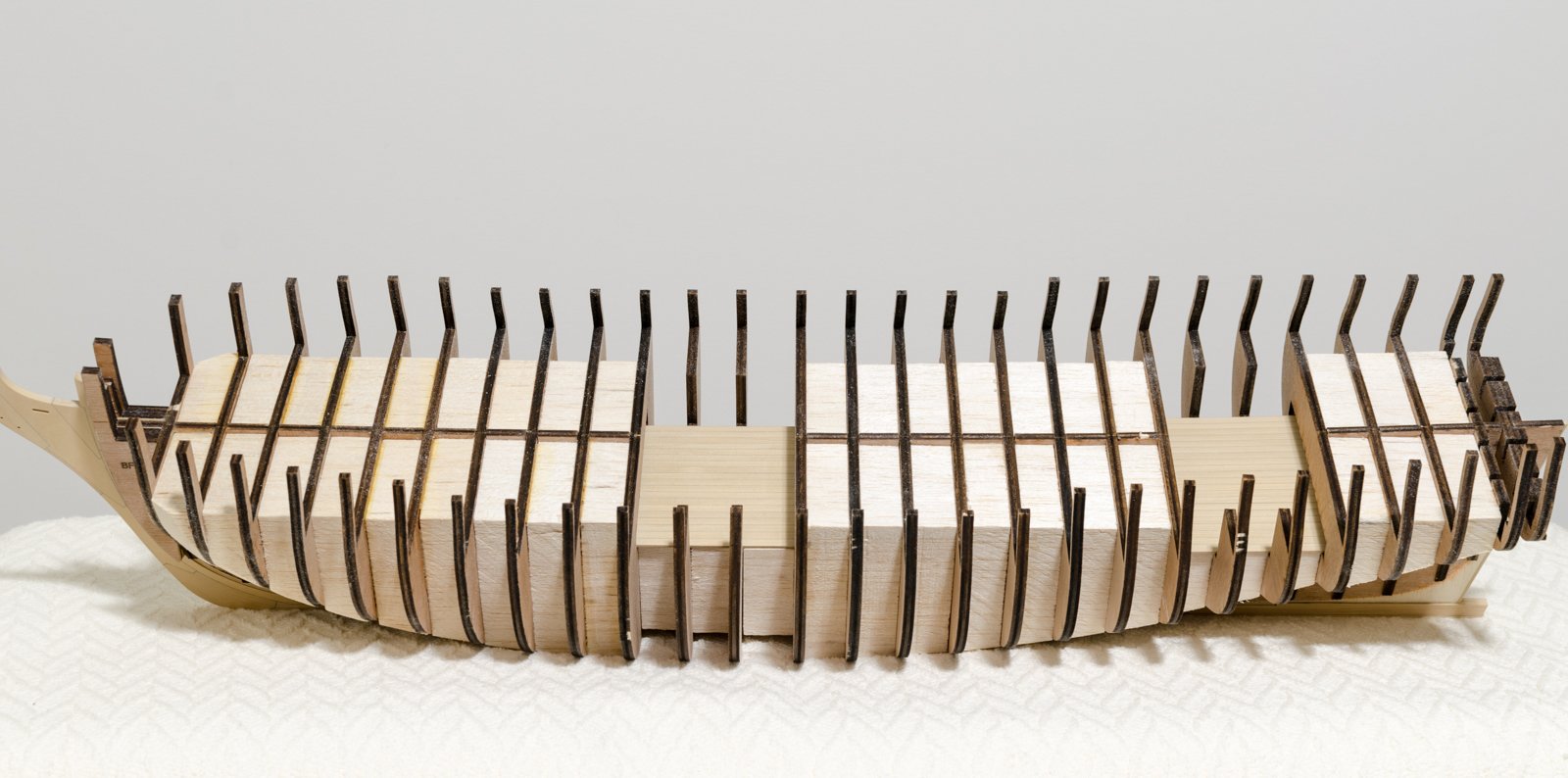
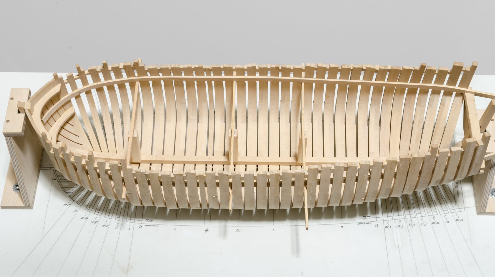
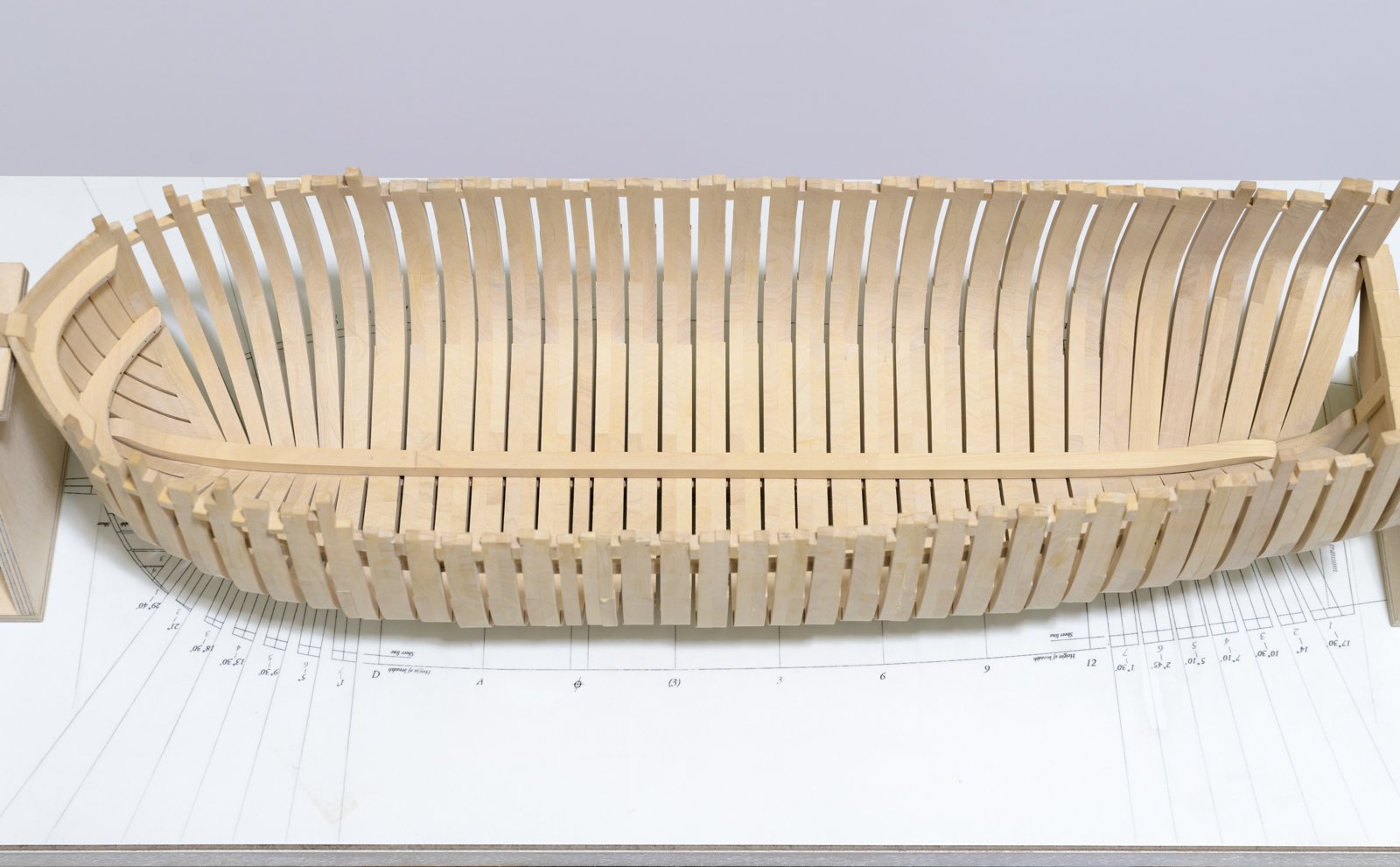
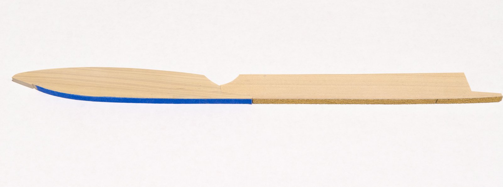
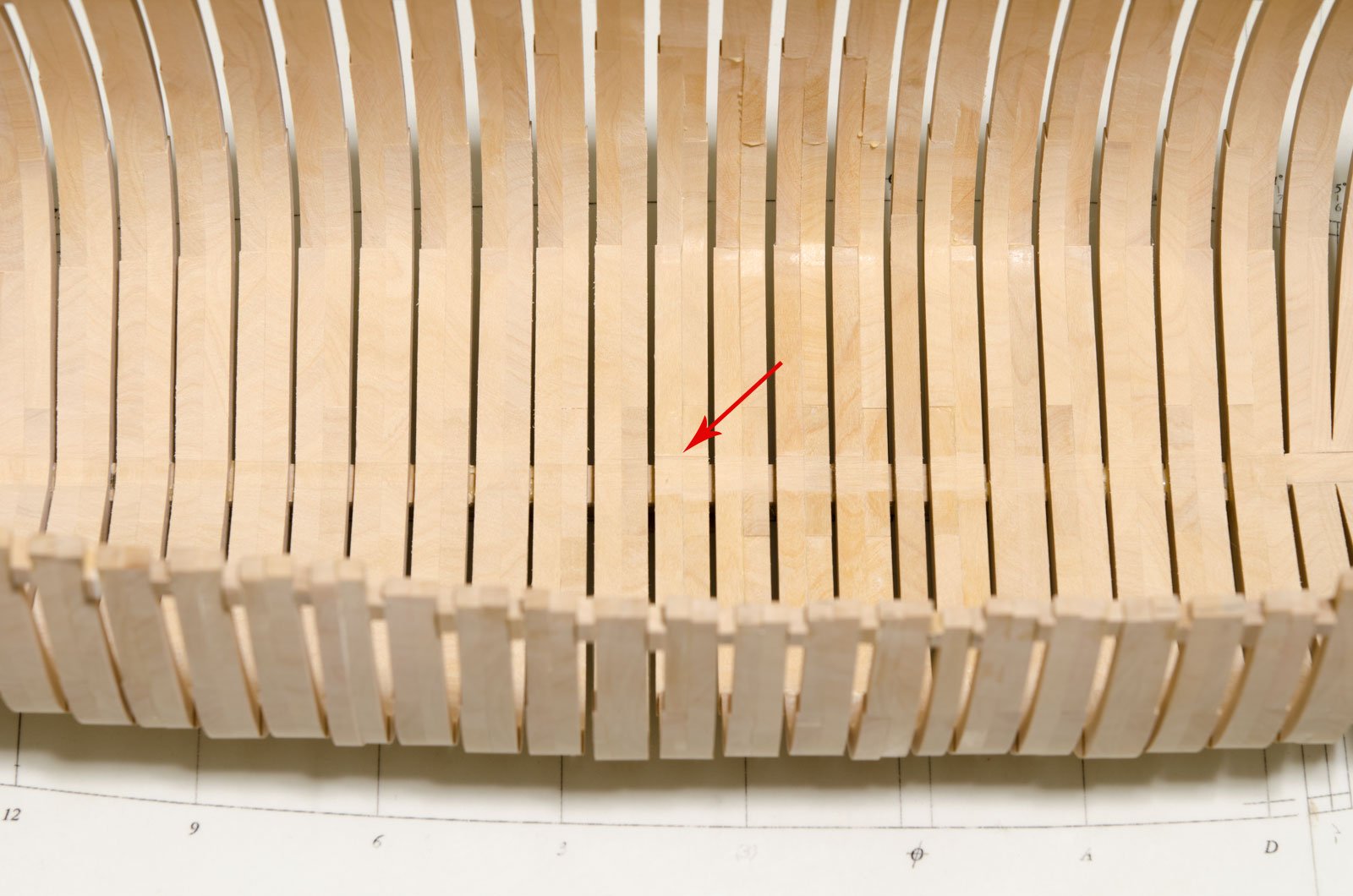
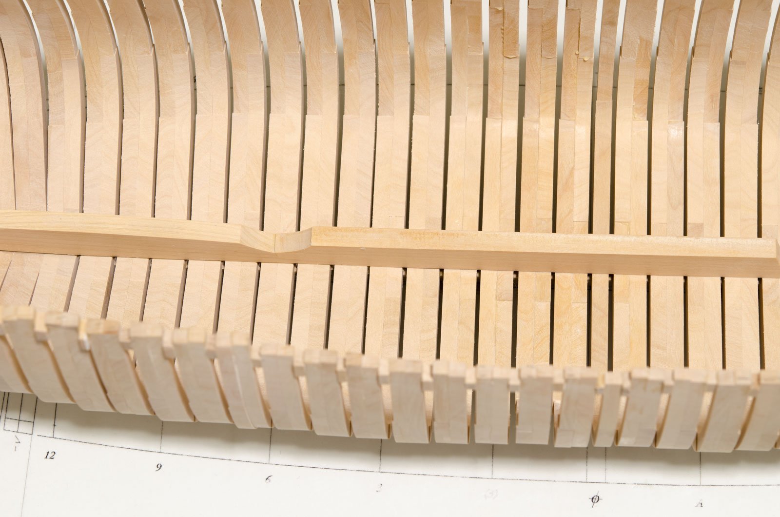
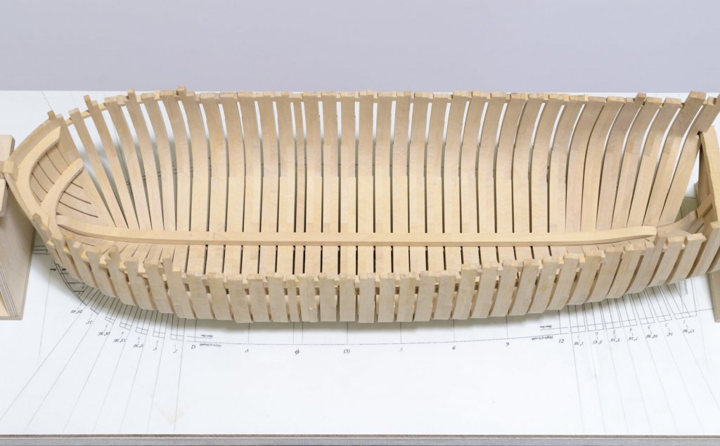
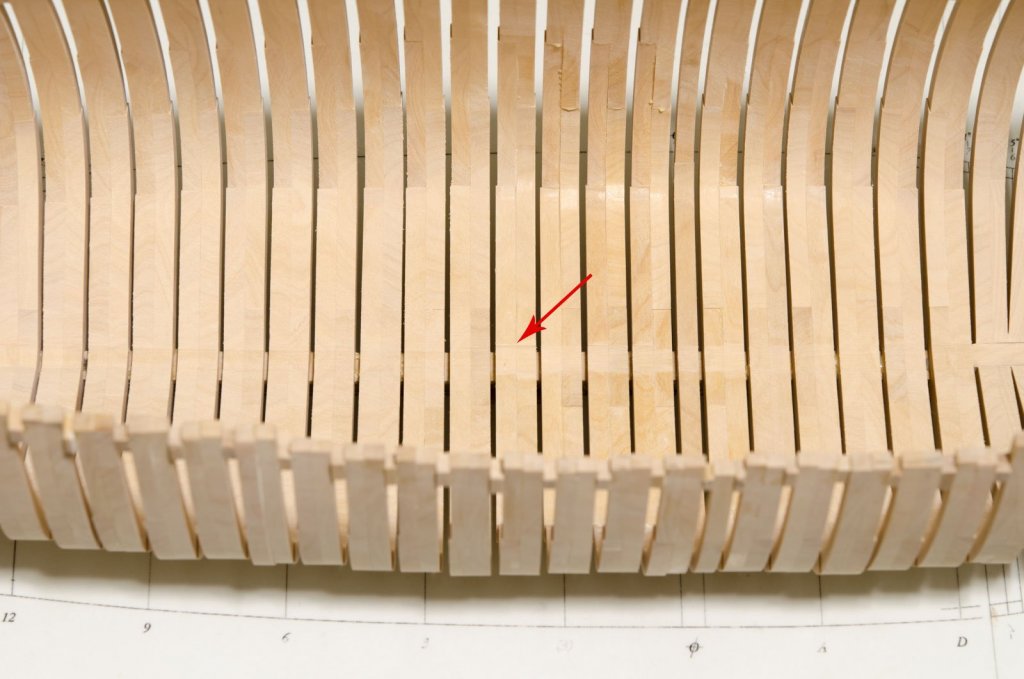
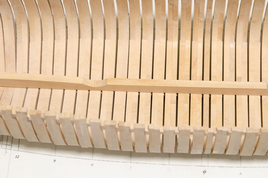
Thank you all for your comments and "Likes" My plan for fairing the frame floors. . I started fairing the inner hull at the toptimbers which was easy enough. As I moved down toward the frame floors, I realized that I had to establish the height of each floor above the building board while getting the overall slope to match the shape of the keelson. To do this, I decided to make the three section keelson, using each section as a sanding block. Each section was left quite a bit higher so I would have something to hold onto. Sticky back sandpaper was adhered to the bottom face. So, after adding a number of frames, moving the block back and forth, in very short strokes, eventually brought the floors down to match the keelson shape. Floor heights were checked above the drawing board as sanding progressed. Aft section test fit Moving ahead, I added the middle section of the keelson. Sandpaper was added to the middle section and five layers of blue masking tape added to the aft section which matched thickness of the sandpaper. Now I could sand down those frames forward of the aft section without affecting the work already done. Sanding leaves shallow notches in the floors that are too high. Test fit with two sections completed. Mike

-
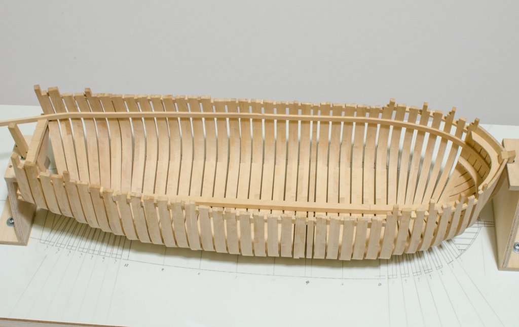
Happy New Year to all! I finally reach a milestone over the holidays, though I still need to do some additional fairing on the inner hull. Once that's completed, I will move onto to installing the deck clamps. They will help to stabilize the hull in preparation for the exterior hull fairing. Mike
-
Steve, Looking at the instruction photos, it appears that the thwarts butt against the frames. Mike
- 190 replies
-
- 1
-
-
- pinnace
- model shipways
- (and 1 more)
-
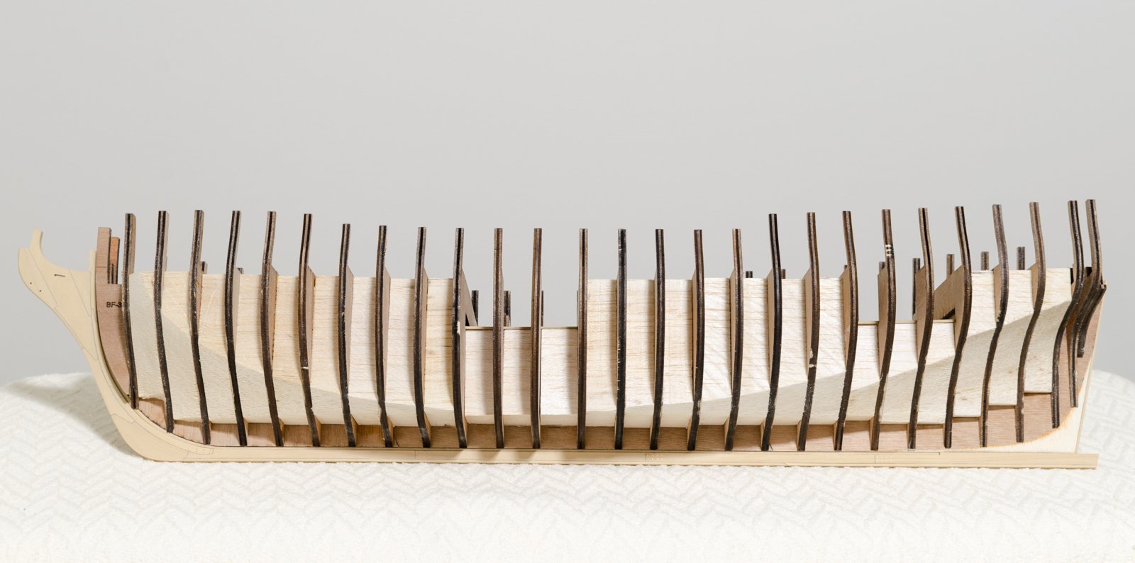
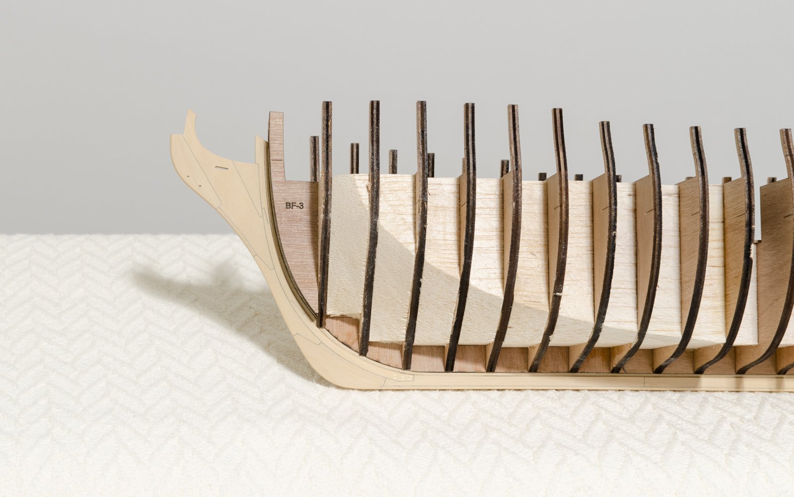
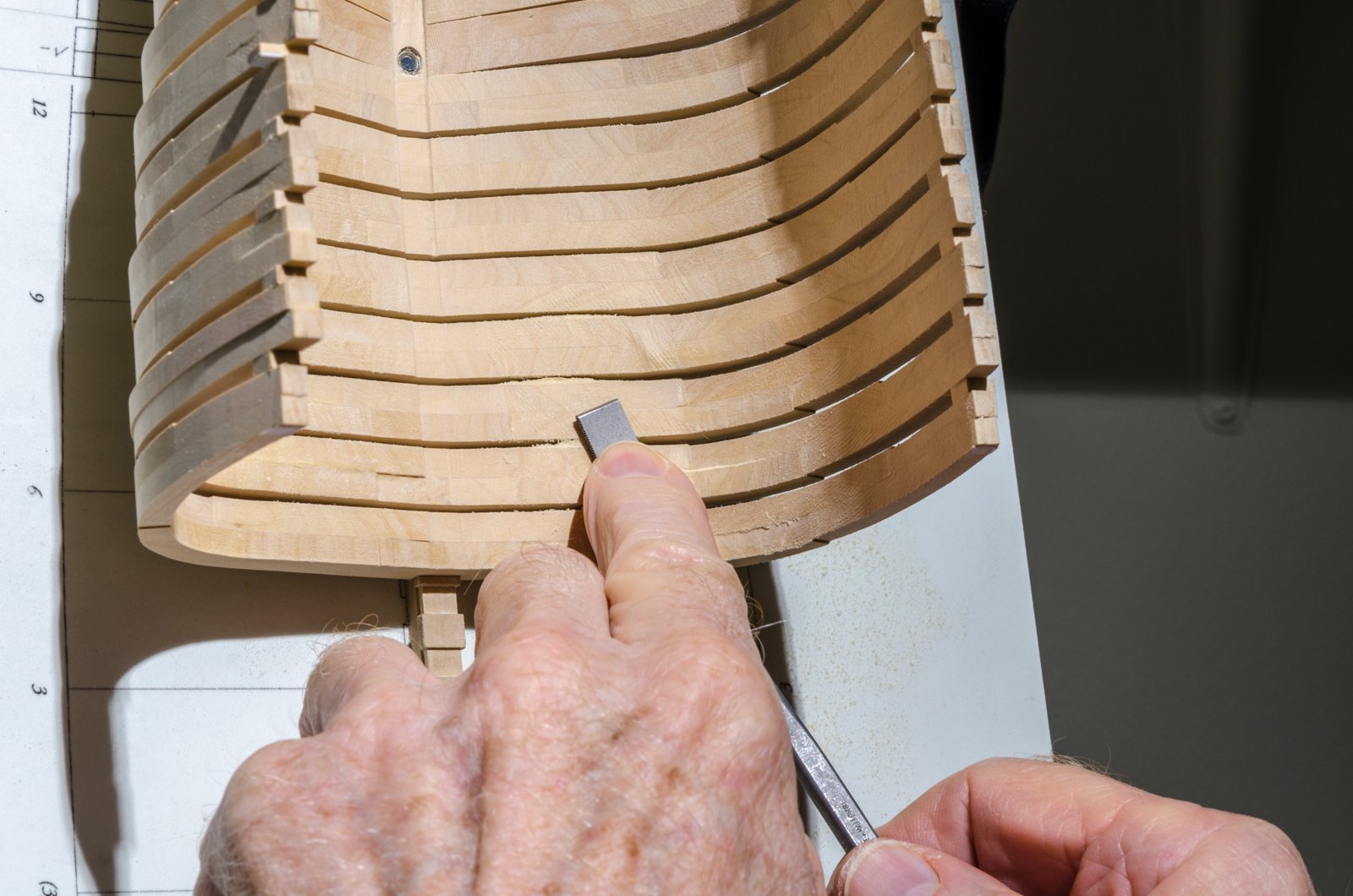
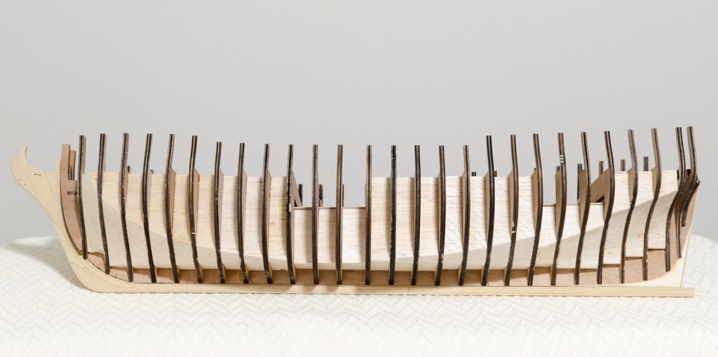
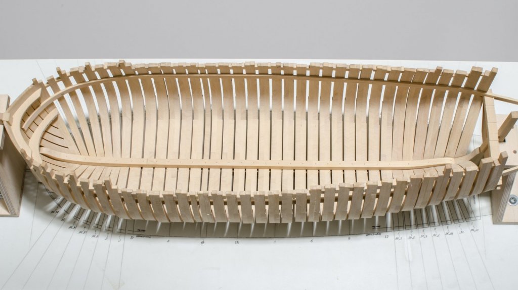
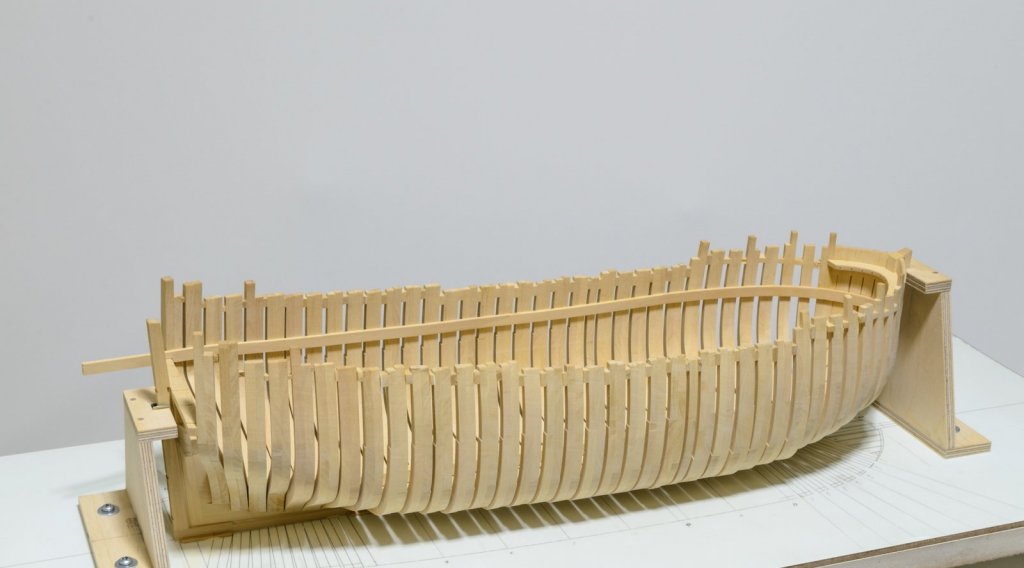
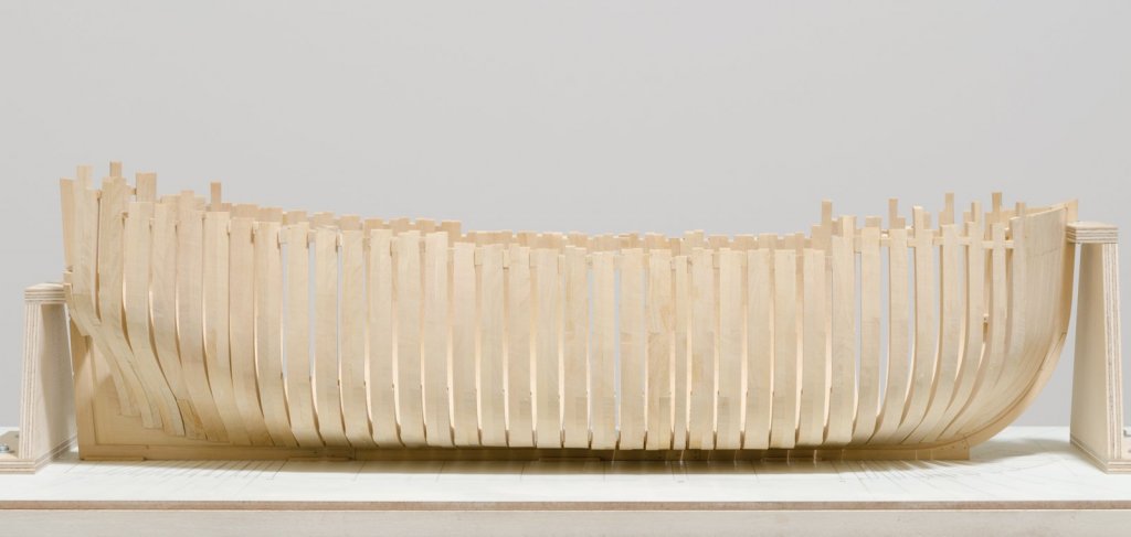
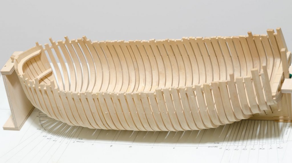
Snowy day here in NY. . Four more frames installed and the usual internal fairing resumes. More work is needed on the previously installed frames to account for the downward slope of the floor timbers and changing angles. All of the frames are cut slightly wide of the drawings, both inside and out, leaving them quite rough looking. Toptimbers are made taller as well. Being my first POF build, I'm not taking any chances in making them too small. It means extra work in the fairing process, but better safe than sorry. Removing one of these would not be a fun. 11 more to go. Rifflers are my go-to tool to start things off. Battens insure that things stay smooth. Mike

-
Beautifully done, Rusty! Looking forward to following your next project. Mike
- 310 replies
-
- 2
-
-
- cheerful
- Syren Ship Model Company
- (and 1 more)
-
Erik, you're welcome and thank you! I finally figured out what was causing the reddish/pink hue in the above photos. It was the overhead light bulbs I was using which were recently changed. I should have known that it was my doing. Mike
- 452 replies
-
- 4
-
-
- cheerful
- Syren Ship Model Company
- (and 1 more)