HOLIDAY DONATION DRIVE - SUPPORT MSW - DO YOUR PART TO KEEP THIS GREAT FORUM GOING!
×


Stuntflyer
-
Posts
1,197 -
Joined
-
Last visited
Content Type
Profiles
Forums
Gallery
Events
Everything posted by Stuntflyer
-
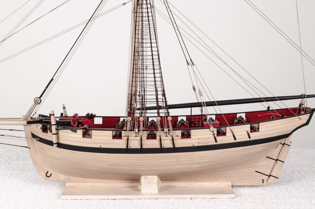
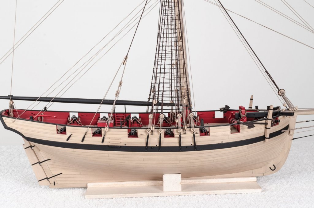
 Thank you Steve, druxey, Thomas, Nils and for all the "Likes" too! The only thing left to do is to get her on a stand and in a case. Mike
- 452 replies
-
- 3
-

-
- cheerful
- Syren Ship Model Company
- (and 1 more)
-
Thanks, Greg! So, I just re-calibrated my monitor after a year of not doing so. The colors are not perfect, but definitely looking better. Mike
- 452 replies
-
- 3
-
-
- cheerful
- Syren Ship Model Company
- (and 1 more)
-
Erik, Sorry or the late reply. I did manage to take a few shots today. However, the new site pushes a reddish/pink hue on all of my photos. . I wonder if anyone else has the same issue. I really need to get started on the stand and case. If I don't, the dust will take over and eventually hide the ship completely. Mike


- 452 replies
-
- 32
-
-
- cheerful
- Syren Ship Model Company
- (and 1 more)
-
Coming along nicely, Steve! The ship has a very clean appearance. Mike
- 190 replies
-
- 1
-
-
- pinnace
- model shipways
- (and 1 more)
-
Thanks guys! You're absolutely right, Greg. . . Before the Hayling build I had no chisel or milling experience so I came up with all kinds of excuses for not making a scored rising wood. A modeler friend cautioned me about POF models and cumulative error issues that can arise. With that in mind I purchased a mill to make the scores. Now that I'm installing frames I can see the advantage in having them. Mike
-
A bit more progress over the past week. With a number of frames completed it doesn't seem nearly as intimidating as I thought it would be. Only 15 more. Mike
-
Almost there, Rusty and looking great! Nice work on the buoys. Mike
- 310 replies
-
- 1
-
-
- cheerful
- Syren Ship Model Company
- (and 1 more)
-
Thank you, druxey! Mike
-
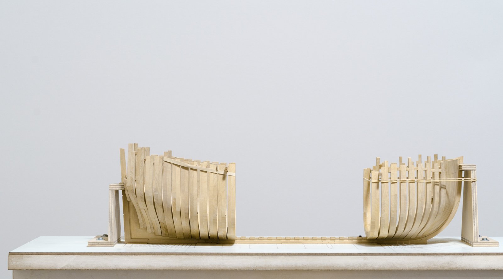
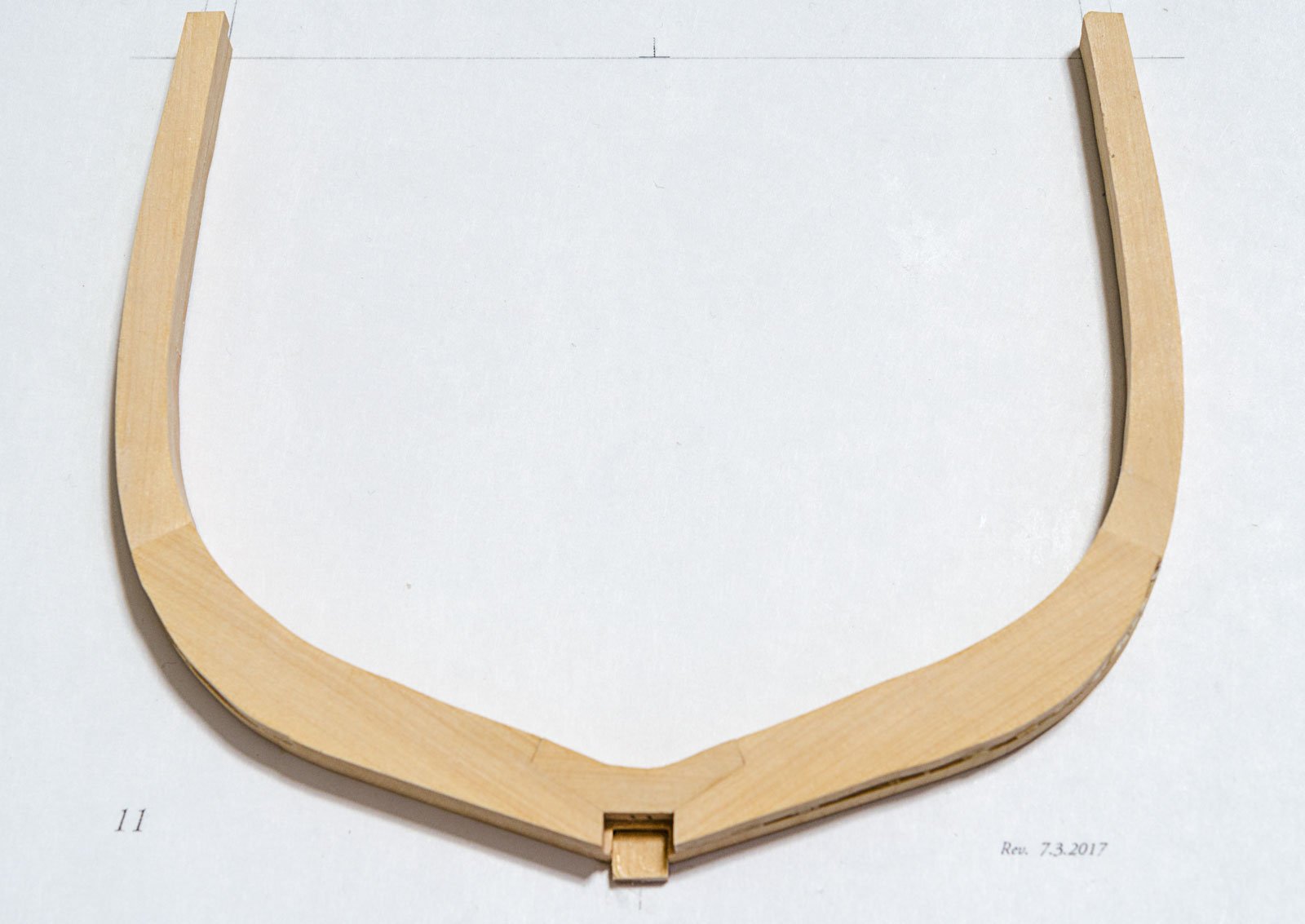
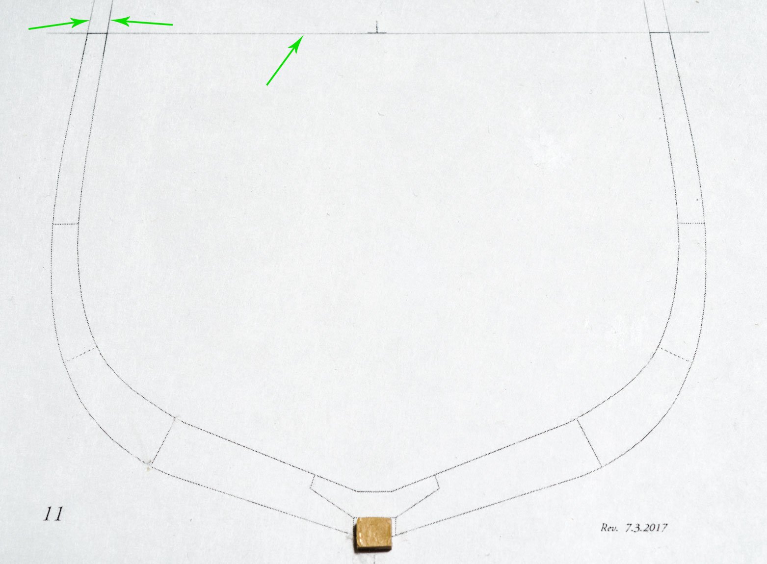
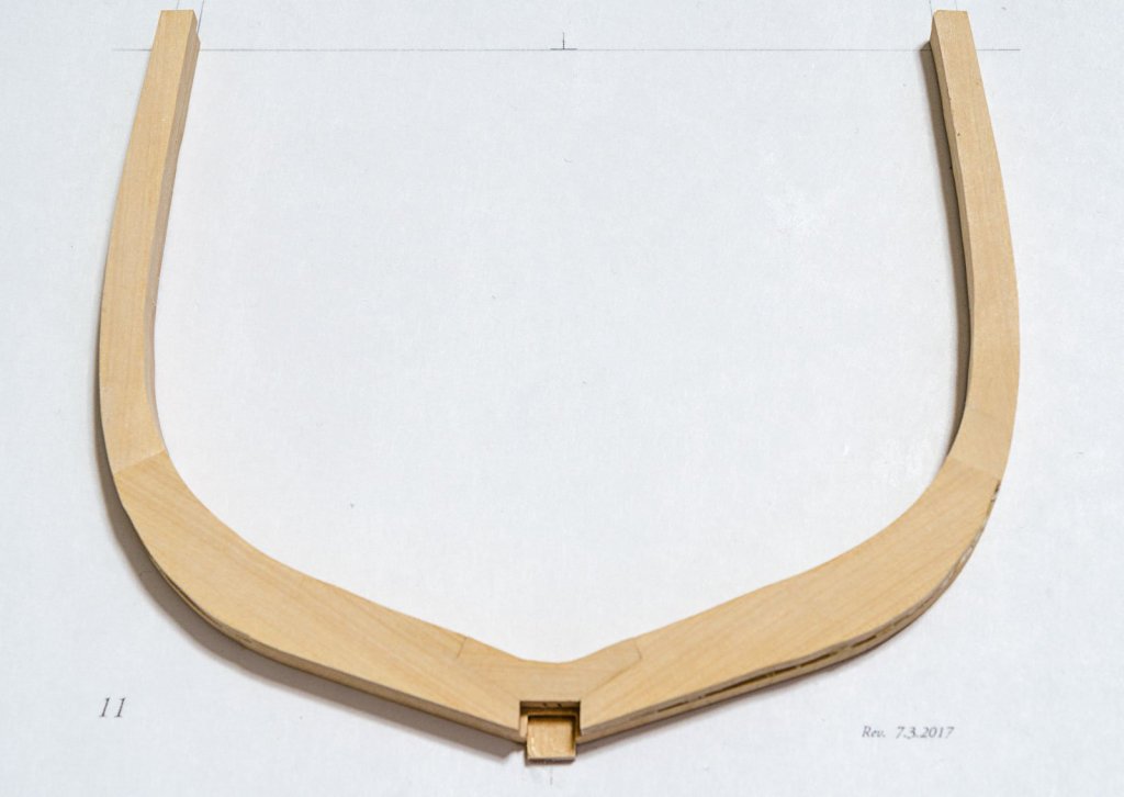
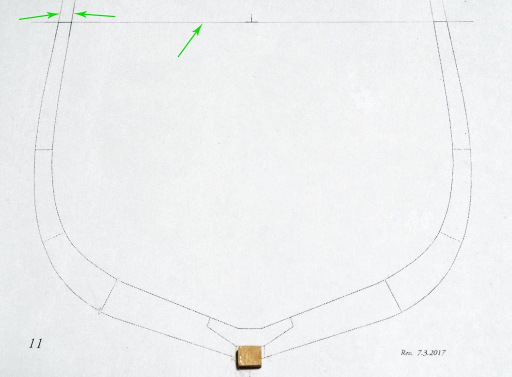
This is how I go about determining the height of the top timbers prior to attaching the cross-spall. A printout is made of the frame drawing and reference lines are drawn. All of the the floors of these 21 frame pairs are notched 1/4" wide. Thus, a scrap piece of 1/4" wide boxwood is glued to the printout at the location indicated on the drawing. Simply place the floor side of the frame pair over the 1/4" boxwood piece and nudge the frame into position. Reference lines can then be drawn on the side of the frame at the top timber line. I find that the boxwood piece is like having an extra hand. Mike
-
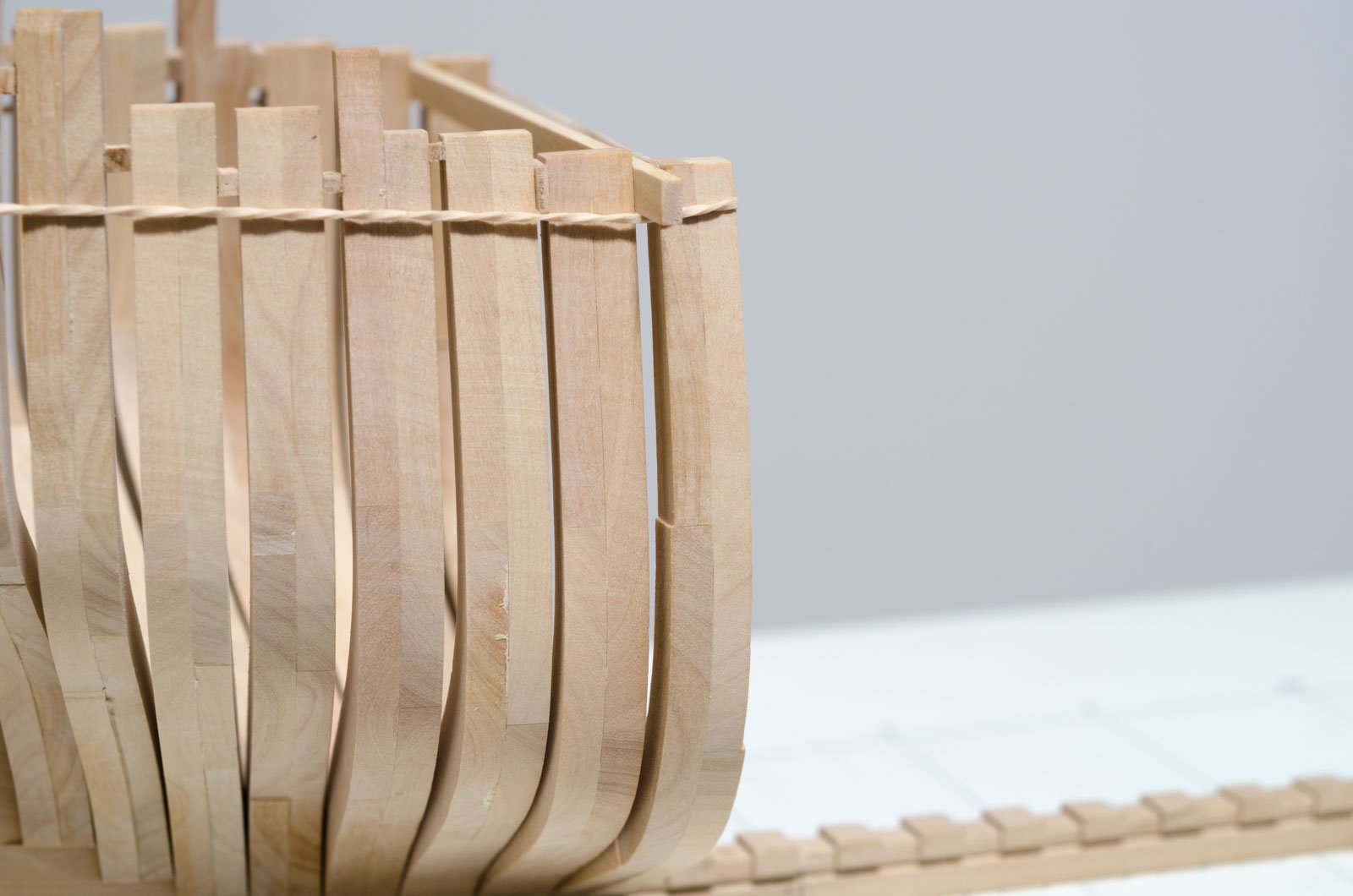
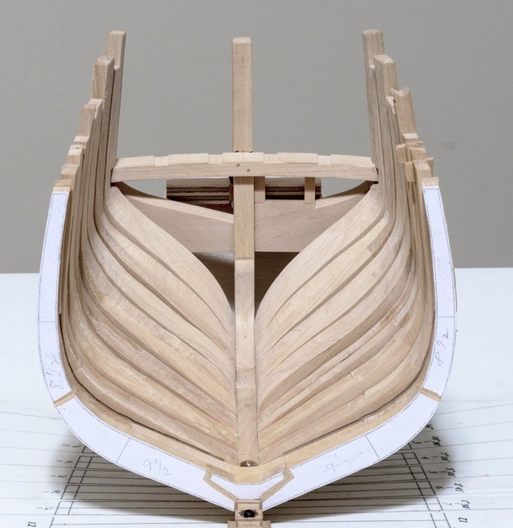
Well, I have finally completed the first of the the 21 square body frames. A temporary cross-spall was placed (tack glued) across the frame pair at the height of the top timber. It is cut to the width necessary to set the frame vertical. I used the cross-spall to level the frame across the ship by measuring at both ends vertical from the build board. A rubber band is all that was needed to hold everything in place after gluing. Mike

-
Thank you all! Tom, I'm semi-retired which gives me time to build almost every day. I considered boxwood which of course is great to work with, but I wouldn't be able to use Chuck's laser cut parts. Chuck did not approach me with the idea to build a prototype. I have always liked the Winchelsea and when I mentioned my wanting to build her, he suggested that I wait until version II was finalized. He happened to have had the head knee parts available for me to try out. Mike
- 607 replies
-
- 11
-
-
- winchelsea
- Syren Ship Model Company
- (and 1 more)
-
Thanks, guys! Nils: I agree that it is a very beautiful ship. Ian: Check with Chuck on this as I have not spoken to him in the last week or so. Mike
- 607 replies
-
- 7
-
-
- winchelsea
- Syren Ship Model Company
- (and 1 more)
-
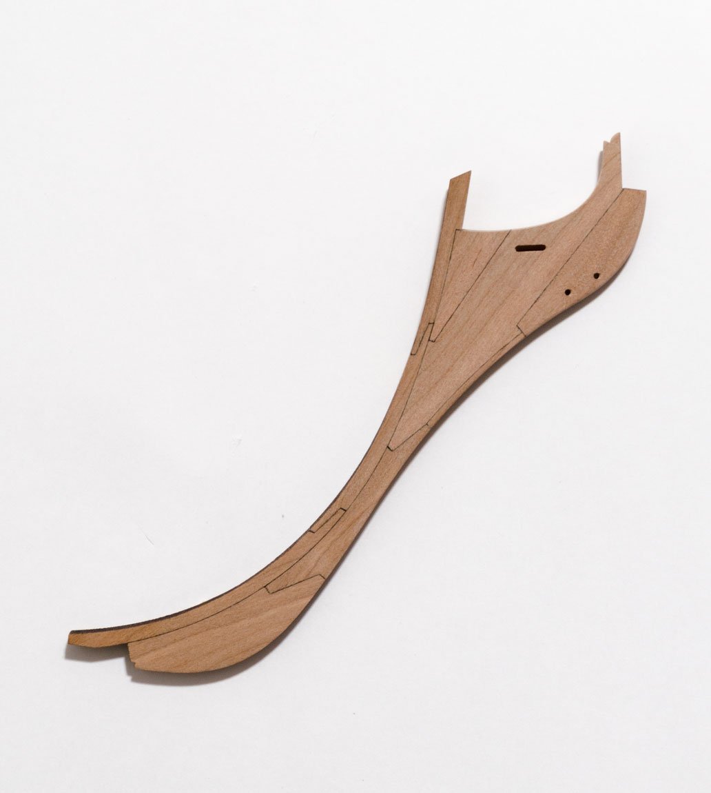
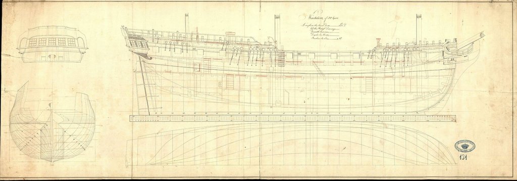
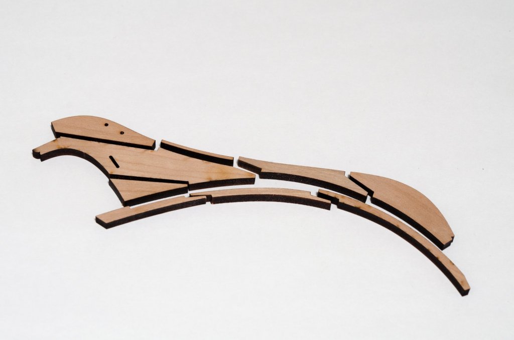
Welcome to my Winchelsea build which will be done alongside Hayling. It will be based on Chuck's version II design. I have chosen to build the ship mainly from Cherry. It will be a P.O.B. model, using the laser cut parts and mini-kits that Chuck will offer. This will be a fun build for me and I'm looking forward to the many challenges that are ahead. The build starts with making the Knee of the Head from Chuck's laser cut kit. Cherry, being a softer wood than Boxwood, cuts somewhat cleaner and the pieces fit together quite nicely. Only a gentle scraping with a #11 blade was needed to remove the loose char. I used a #2b pencil to darken all the joints (optional) which were then joined with Elmer's Carpenter's Wood Glue. No clamping was necessary. The upper area from the stem down to the forward edge of the bobstay piece was gradually tapered from 3/16" to 3/32". The bobstay holes and gammon slot edges were softened as well. Mike

- 607 replies
-
- 27
-
-
- winchelsea
- Syren Ship Model Company
- (and 1 more)
-
Mark, Kurt and Michael, thank you for the kind words. Kurt: I do all the photography under incandescent lighting (no flash) on a tripod with an 80A conversion filter on my Nikon D5100. The filter helps to reduce the orange tint created by the ambient light. Photo processing is typical and I rarely do any sharpening or cropping. Of course using a good macro lens helps tremendously. Mike
-
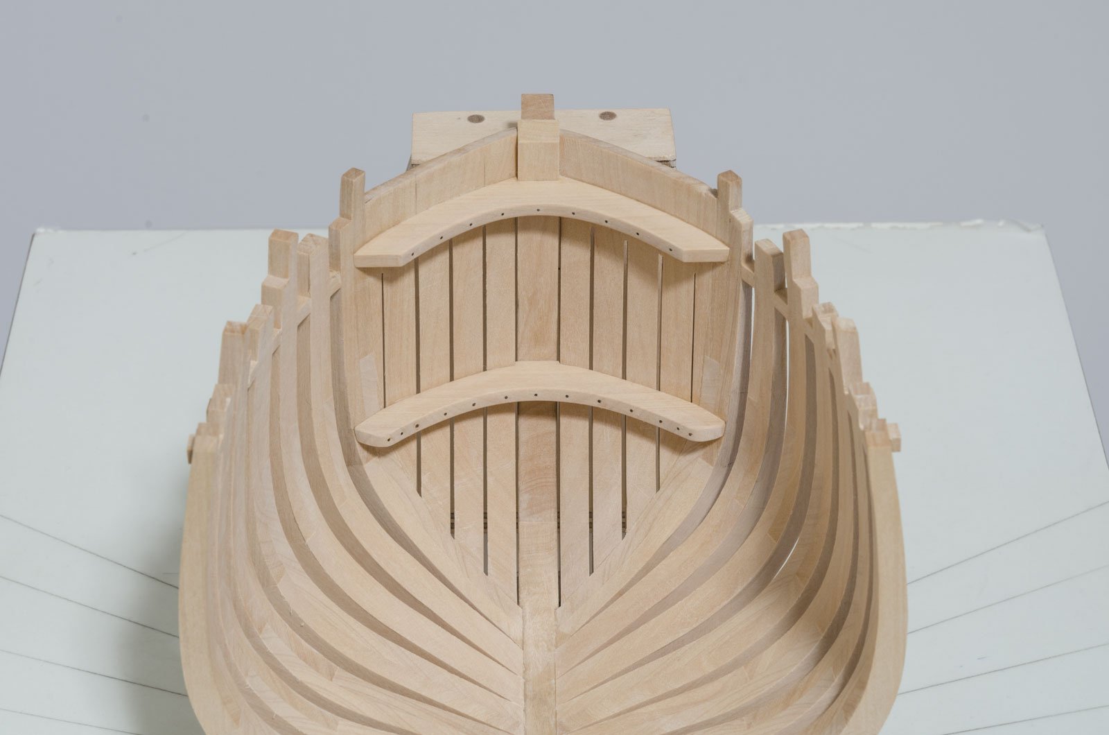
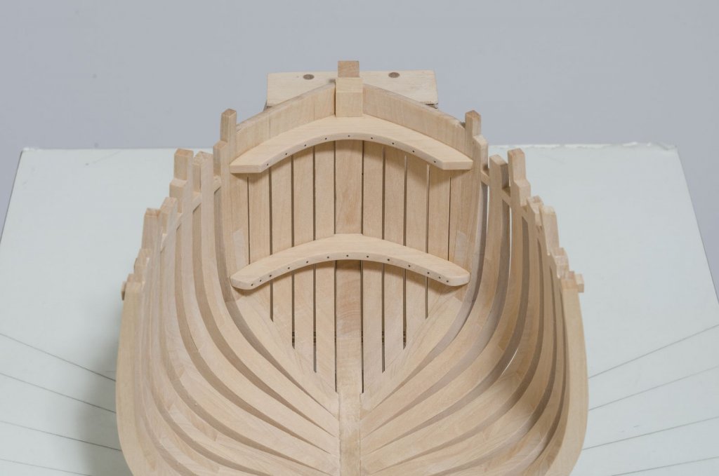
I managed to complete the forecastle deck hook and the breast hook over the last few of days. Both of these required a lot of fiddling in order to get them to fit properly. The angle of their inside edges changes constantly due to the changing angle of the hawse pieces. Bolt holes were drilled through the hooks with a #75 drill. 24 gauge copper wire was used for the bolts. The position of each hook was set prior to gluing and clamping with copper wire. The wire being inserted into three of the holes that were extended about 1/32" into the hawse pieces. After the glue was dry, copper wire was snipped to a pointed shape and pushed firmly into the holes with a needle nose plier. The wire was snipped off leaving about 1/64" showing. Using a wide flat-tip nail set, the remaining wire was pushed (not hammered) into the hole until flush. I was wondering if this method would aid in holding the hooks in place, so I made test piece without using glue. I found that I could not pull it apart easily. I would recommend using this method as it is easier to do and avoids using glue which can be messy. Thanks for the tip, druxey! Liver of Sulphur was diluted 10:1 and applied to the copper wire for blackening. Mike
-
A bit more progress as the remaining fore cants are now installed. Two machinist squares and a Q-tip hold things steady while cant #5 sets up. Mike

-
Looks great, Thomas! Mike
-
I will leave things as they are then, druxey. Mike
-
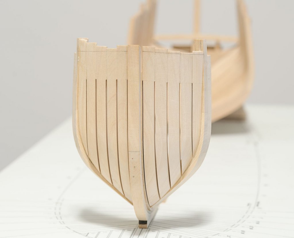
The bollard timbers and hawse pieces are now completed. I left room for final fairing later on after all the frames are in. I didn't notice it earlier, but it appears that the upper limit of the air spaces should be shaped to a point and not square. Guess I will need to come up with a solution to achieve that and not do damage to any of the work already done. Mike
-
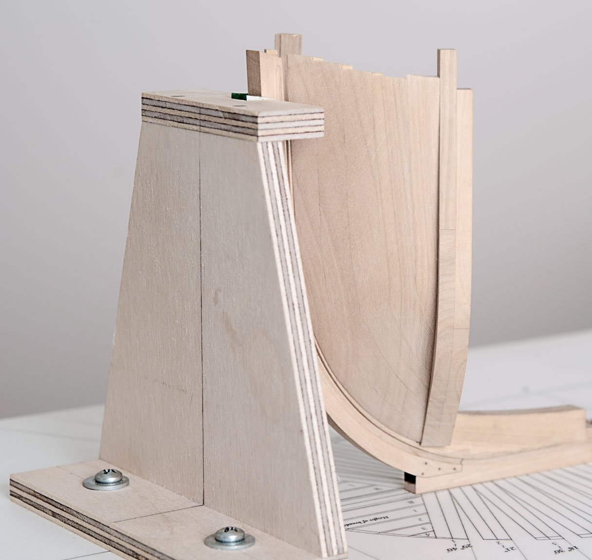
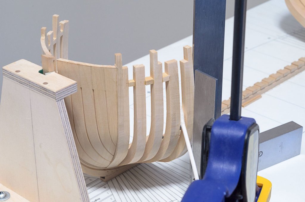
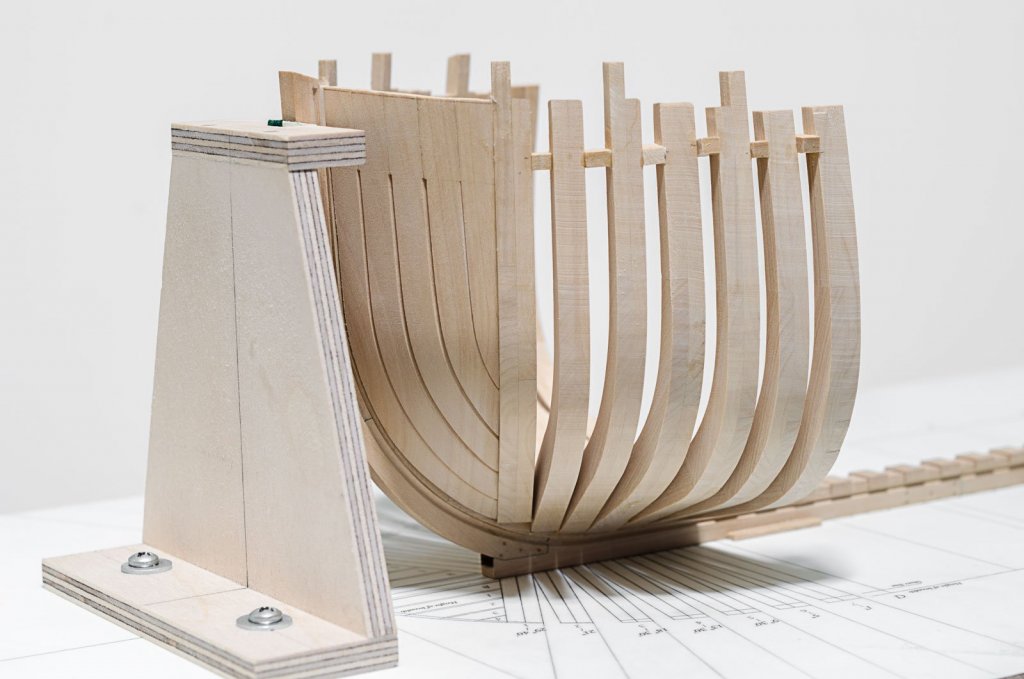
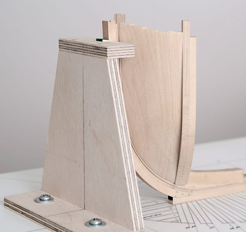
The first of seven fore cants was made and installed. I was careful in making sure that it was vertical and at the correct angle to the keel. Rather than using my homemade 90° plywood jig, I now find it easier to align the cants with just two machinist squares and a little hand holding. The trick is to establish the exact angle needed at the foot of the cant and hold it down securely to the stepping line while the glue quickly sets. Once the cant frame was installed I started to work on the Bollard timbers and hawse pieces. I ended up making three sets before I was satisfied with the shape and fit. Luckily, they don't require using a lot of wood. Mike
-
druxey, I removed just enough wood to reach a faired state and not a bit more. Lower timberheads around 9" or 9 1/2". Timberhead tops between 7 1/2" and 9". I'm hoping that's good. Mike
-
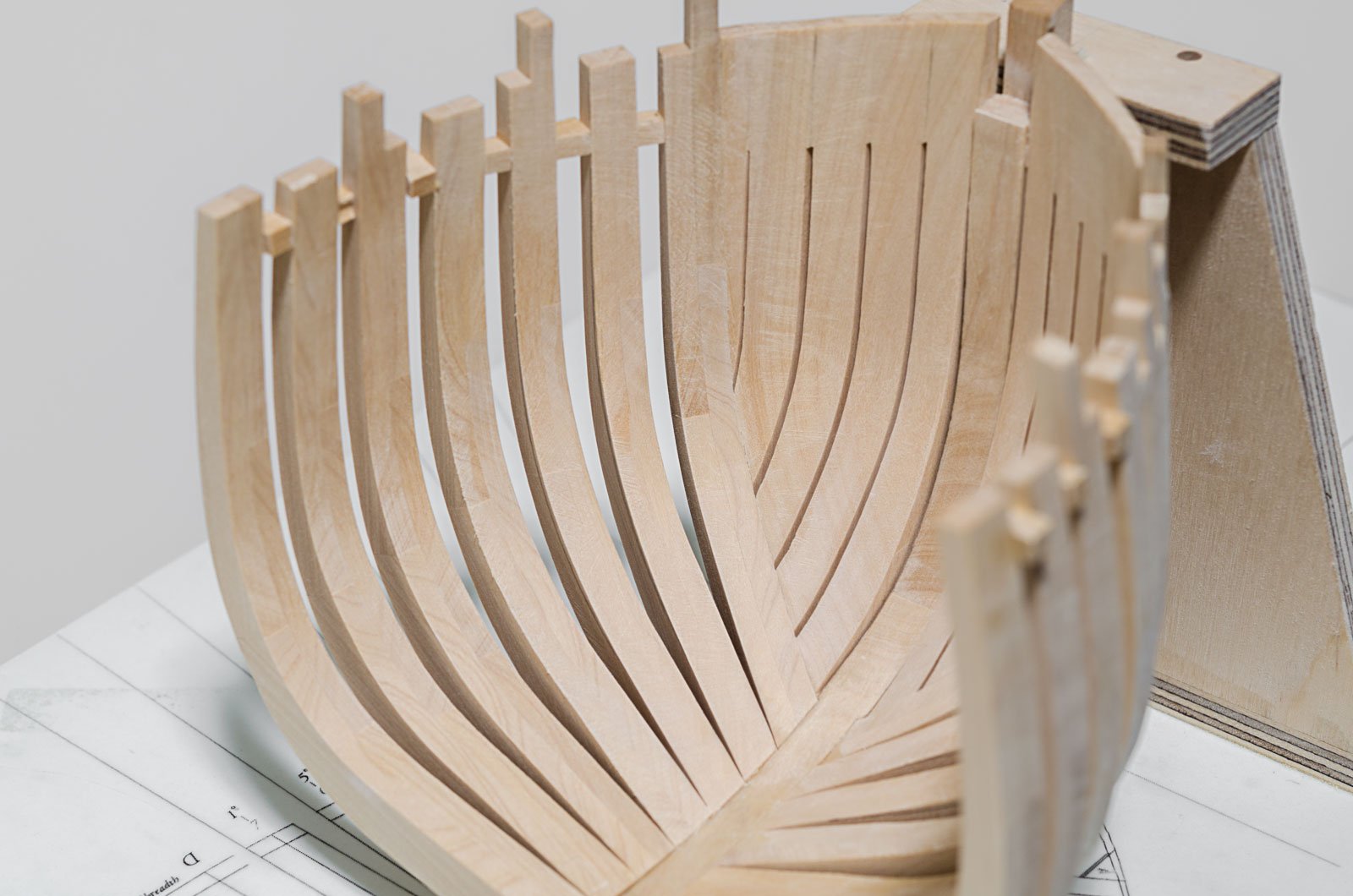
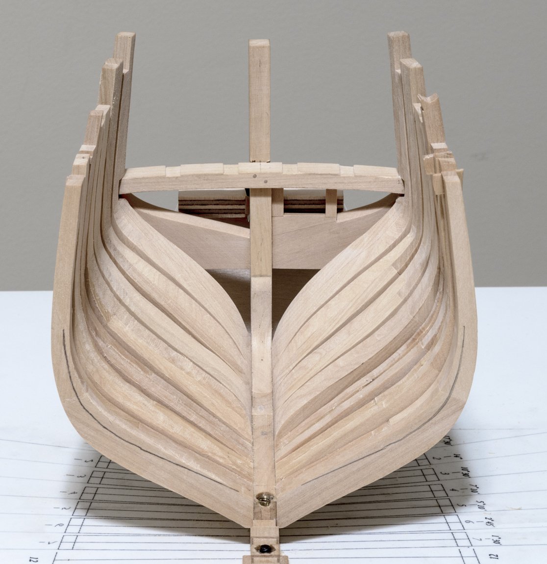
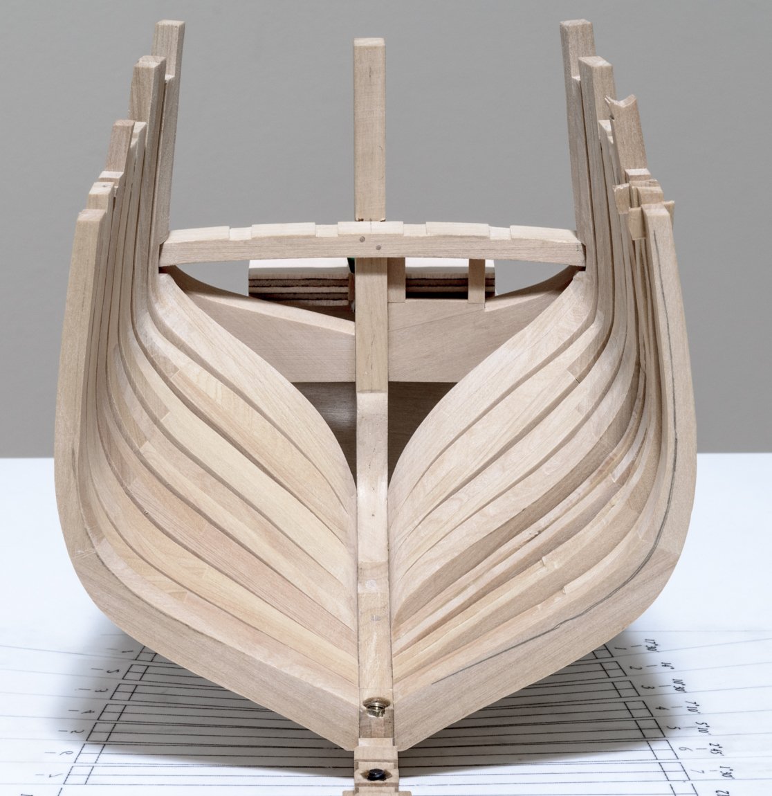
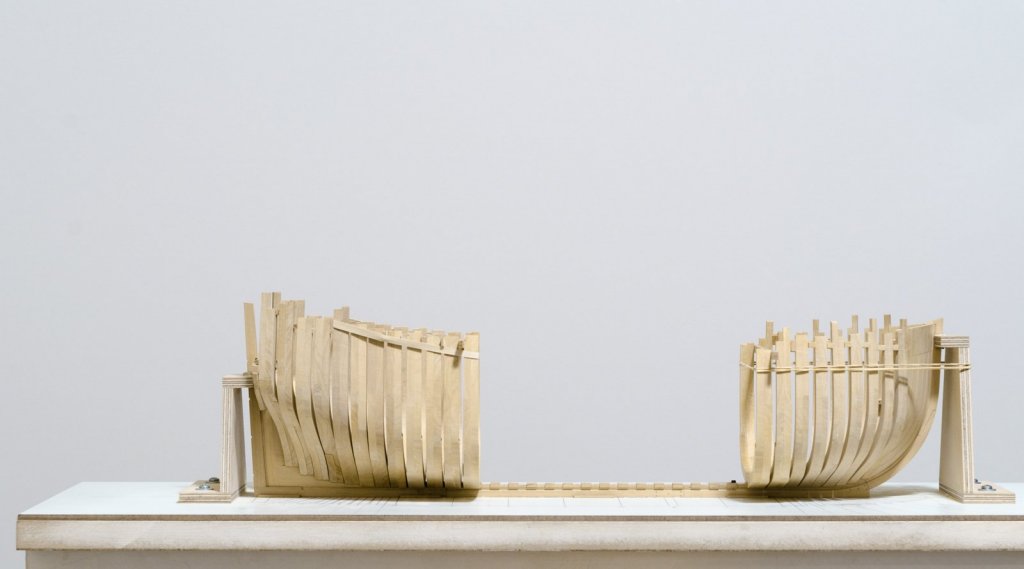
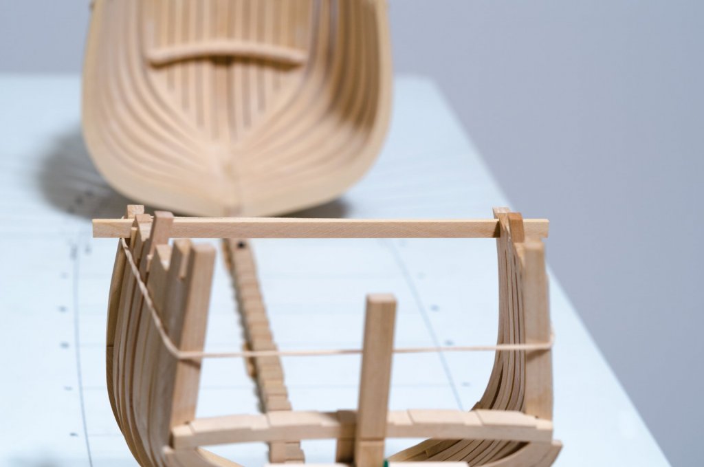
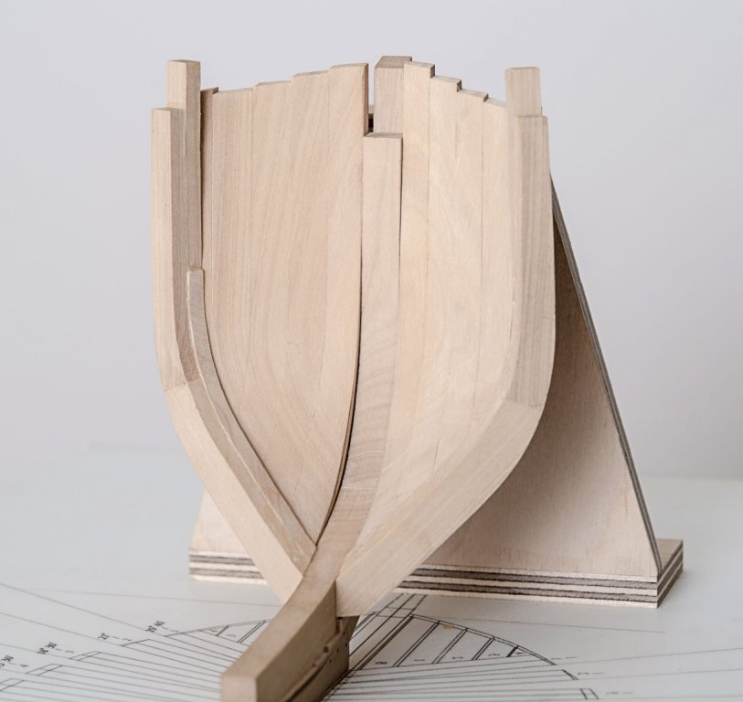
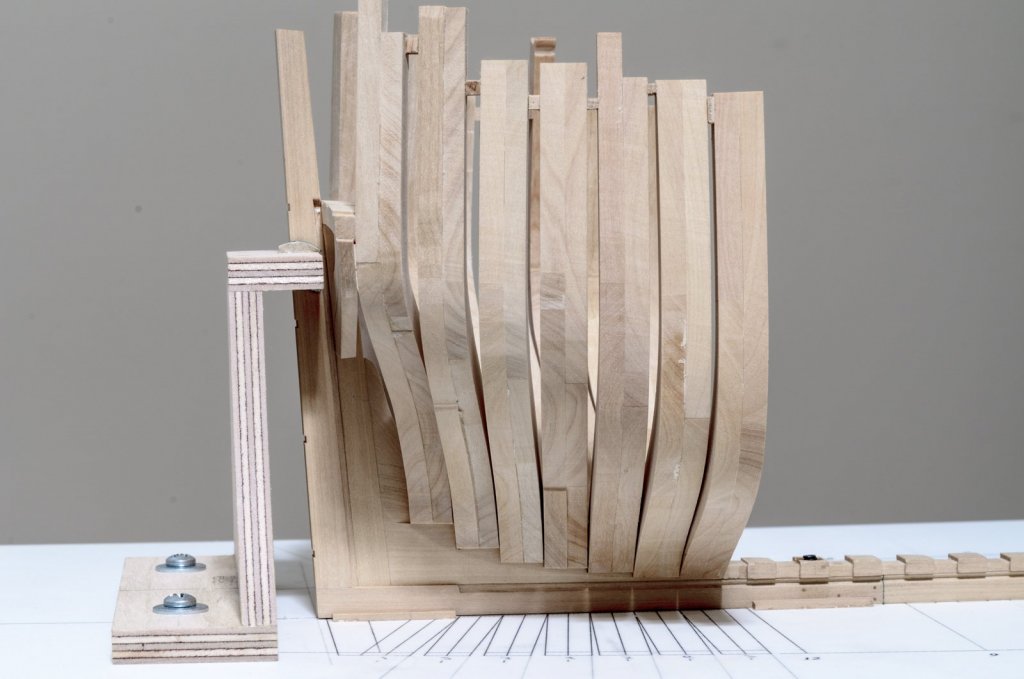
Frame making continues with the completion of the seven aft cants. While fairing the last three aft cants, AC 5-7, it occurred to me that I had no idea as to where the stop line would be for the forward most one, AC 7. My solution was to use the square body frame just forward AC 7 for marking out a reference line to fair to. I tried making a few square body test frames a while back. Needless to say, improvements have been made and are on-going. I will explain how I make them when I start to produce them in quantity. With the square body frame in place, a reference line is drawn slightly above its edge onto AC 7. If you look at the port side you can see just how much wood needs to be removed, including those frames previously faired. The square body frame has been removed and fairing can continue. With the starboard side fairing completed I can now place a batten anywhere and get a smooth run. It's probably too much finish work at this stage however, I don't mind the extra work as I find it quite enjoyable. Fairing a few frames at a time rather than all at once gives one a lot more room to work. My hand was outside the hull most of the time. Now its on to the port side. I see that I need to cut down that too tall toptimber on the port side too, Ooops! For this work I prefer using hard edge tools along with the Dremel rather than sandpaper Mike


-
Cliff, this is what I used. https://contenti.com/901-die-sinkers-riffler-files https://contenti.com/no-604-silversmith-s-riffler Mike