HOLIDAY DONATION DRIVE - SUPPORT MSW - DO YOUR PART TO KEEP THIS GREAT FORUM GOING!
×


Stuntflyer
-
Posts
1,197 -
Joined
-
Last visited
Content Type
Profiles
Forums
Gallery
Events
Everything posted by Stuntflyer
-
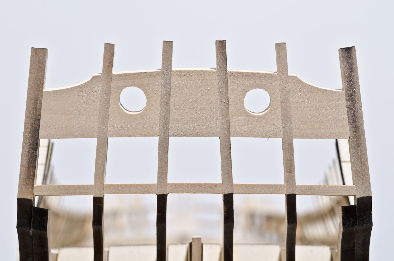
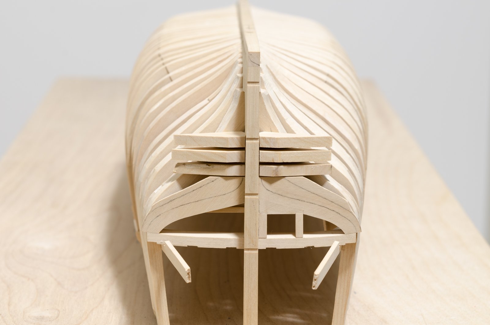
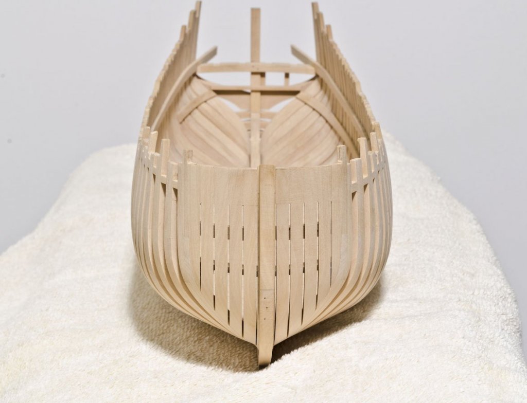
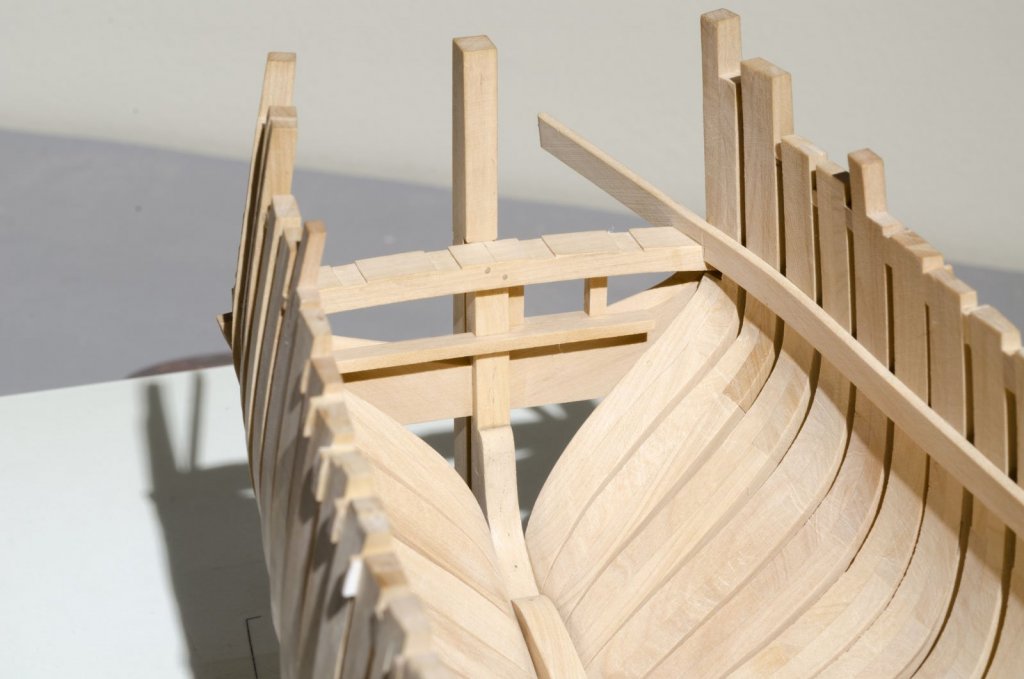
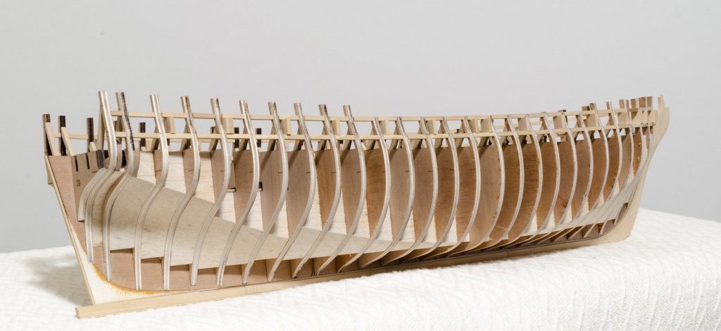
 The four hance pieces are in. They were laser cut from yellow cedar and set proud in order to shape them to the outboard hull shape. A cross spall was used to insure that they sit straight. Mike
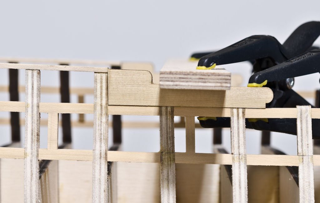
- 607 replies
-
- 25
-

-
- winchelsea
- Syren Ship Model Company
- (and 1 more)
-
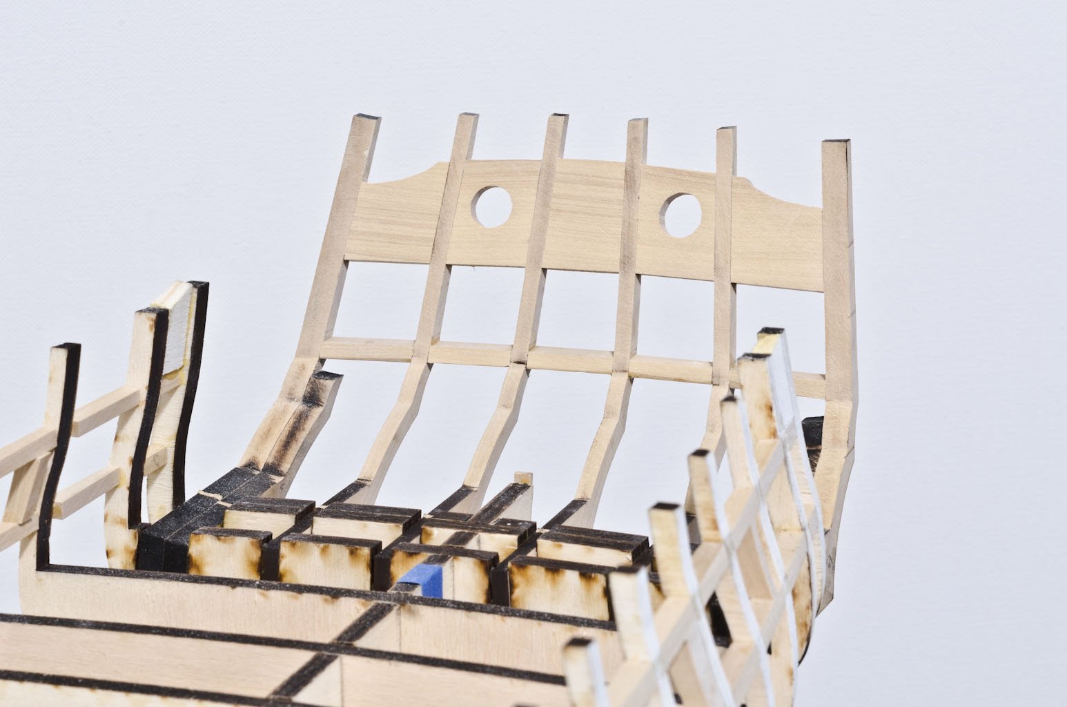
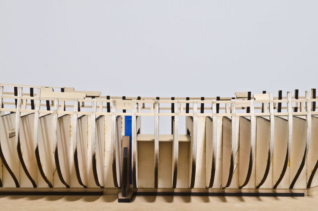
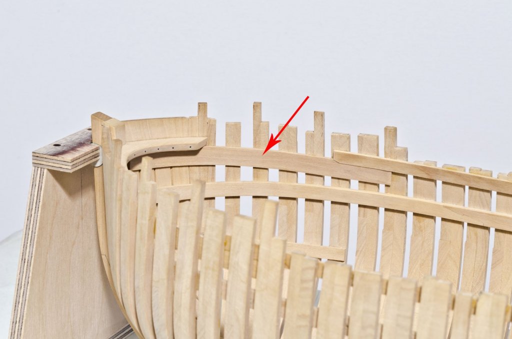
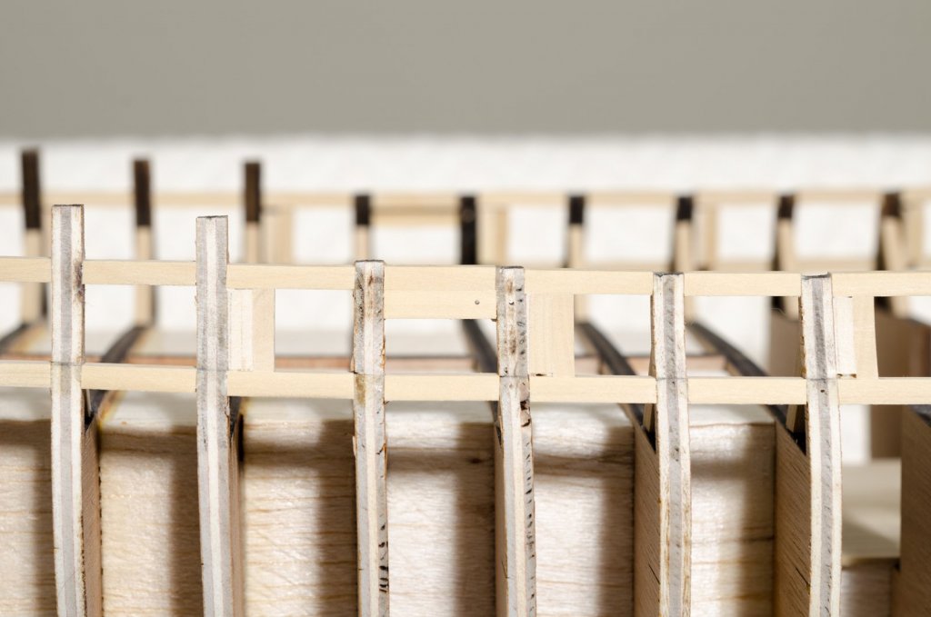
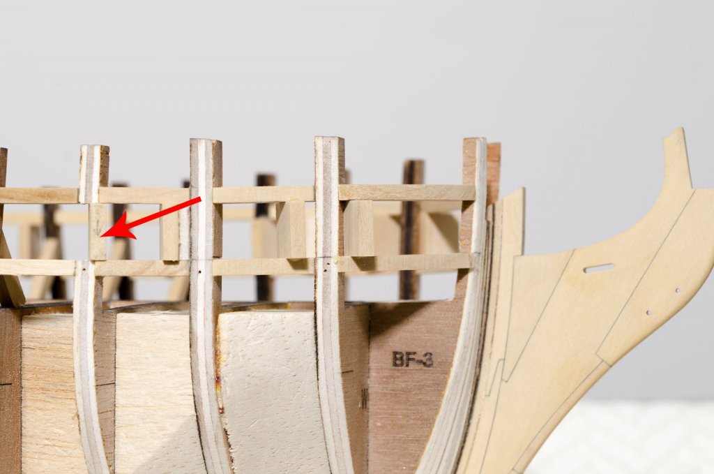
Thank You, Maury and for all the "Likes"! The quarter gallery framing and aft-most gun port turned out to be my week's project. The 5/64" X 1/4" strip along the top of the quarter deck bulkheads was made from basswood. I sanded the bulkhead tops to the correct angles for a smooth flow of the strip. Getting the symmetry from one side to the other took patience and repeated eyeballing. The framing of the quarter gallery required a bit of experimentation. There are a number of angles on each strip and no two strips are the same, except for the two gallery entrance strips. Rather than waste precious boxwood, I used basswood strips to find the correct angles. As an example, one strip had angles of 70° and 10° on one side, 6.5° and 5° on the other. A disc sander with multiple adjustments comes in handy. After completing the horizontal strips I made the two aft-most gun ports. Lastly, the quarter gallery entrance strips were added. The plan detail proved to be very useful for getting exact measurements. All strips were inserted standing proud, allowing for shaping to the hull shape when fairing. I faired the work leaving a wee bit more for later on when I start work on the lower hull. I'm always trying to stay one step back until I'm sure of where I'm going. Mike
- 607 replies
-
- 27
-
-
- winchelsea
- Syren Ship Model Company
- (and 1 more)
-
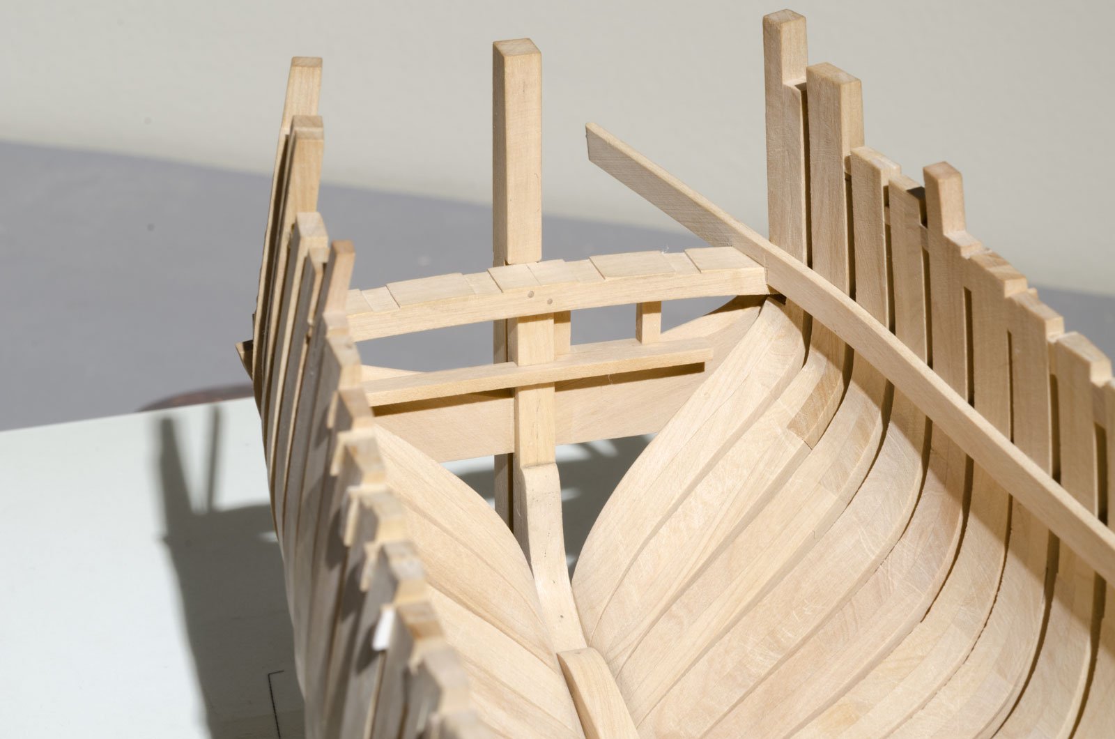
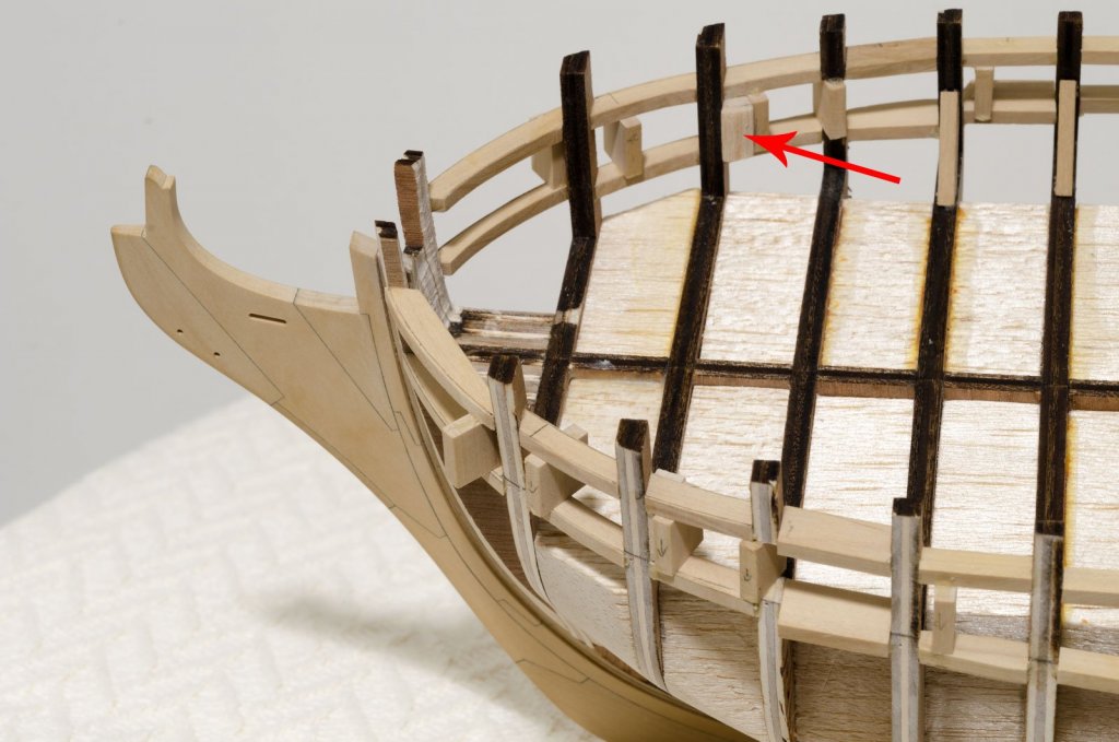
The two forecastle deck clamps were added today. They sit below the stringer at the aft end which allows the forecastle deck beams to sit flush with the top edge of the stringer. At this stage the hull is quite strong. Mike
-
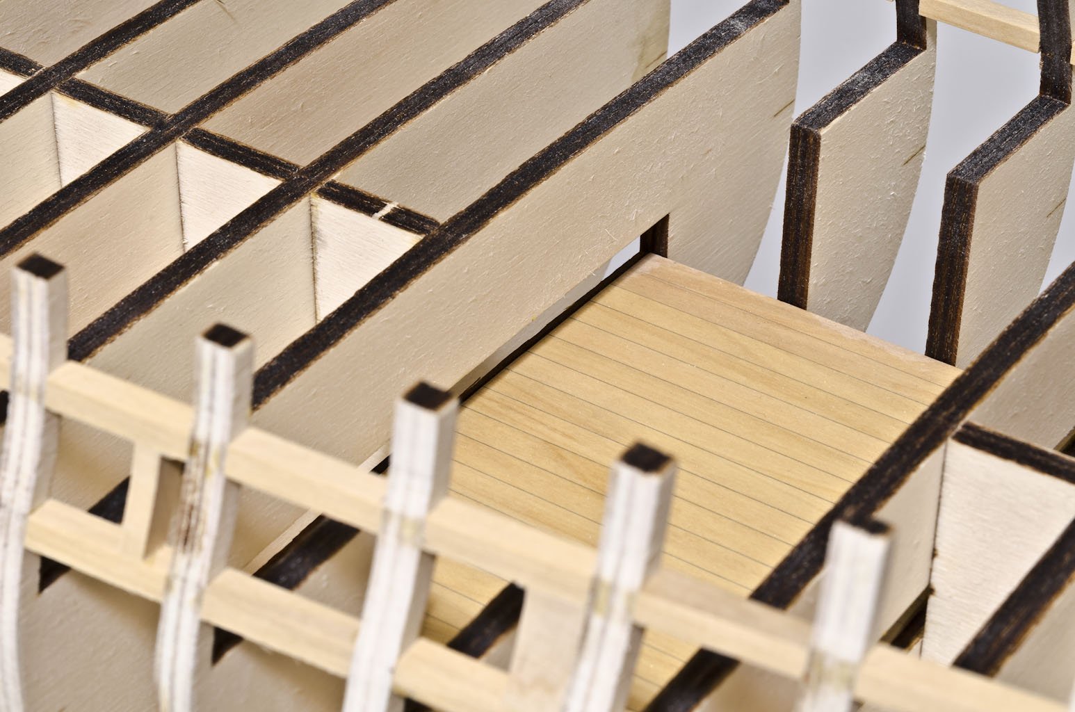
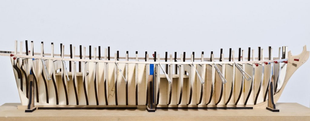
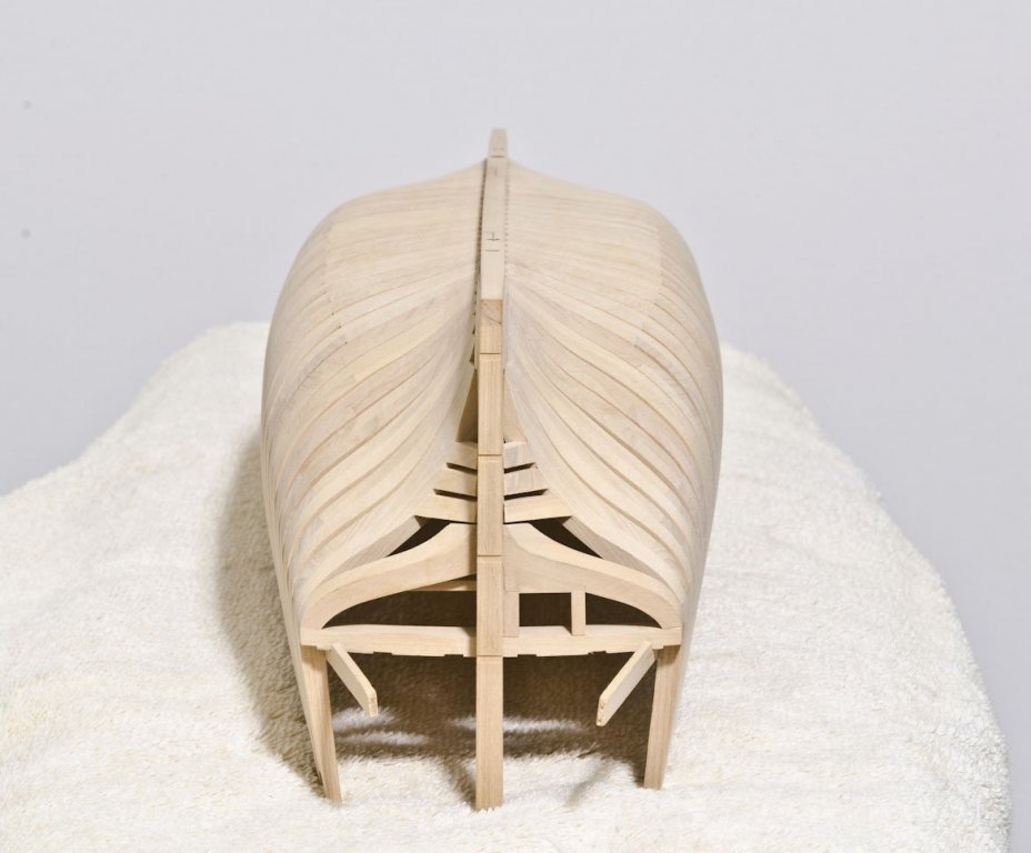
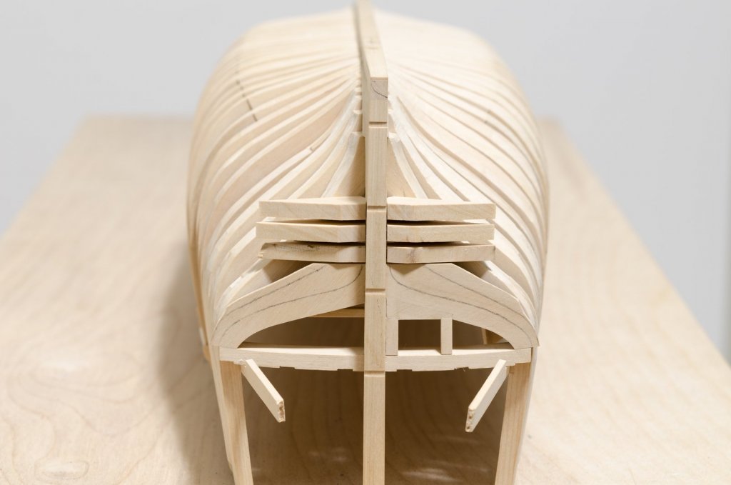
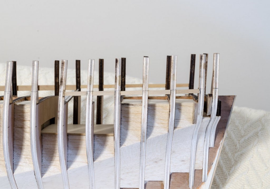
The shop has been a busy place lately. In preparation for the quarter deck clamp/stringer in the waist and Forecastle deck clamp install, it was necessary to remove the small temporary filler pieces between each frame. My method is to wrap the fillers (3-4 at a time) with a moist paper towel and apply a hot clothes iron to the surface of the paper towel. The steam penetrates and loosens the joint. Needle nose pliers can then be used to remove each piece. Final sanding of the exterior hull will be completed later. Using this height gauge, vertical measurements were taken from the shear plan at various locations and transferred to the interior hull. The thin boxwood strip was glued to the gauge with CA and pushed through between the frames, so tic marks could be added. The quarter deck clamp which becomes the stringer in the waist is installed above the upper deck clamp. Mike


-
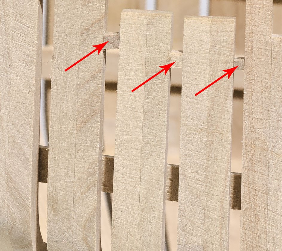
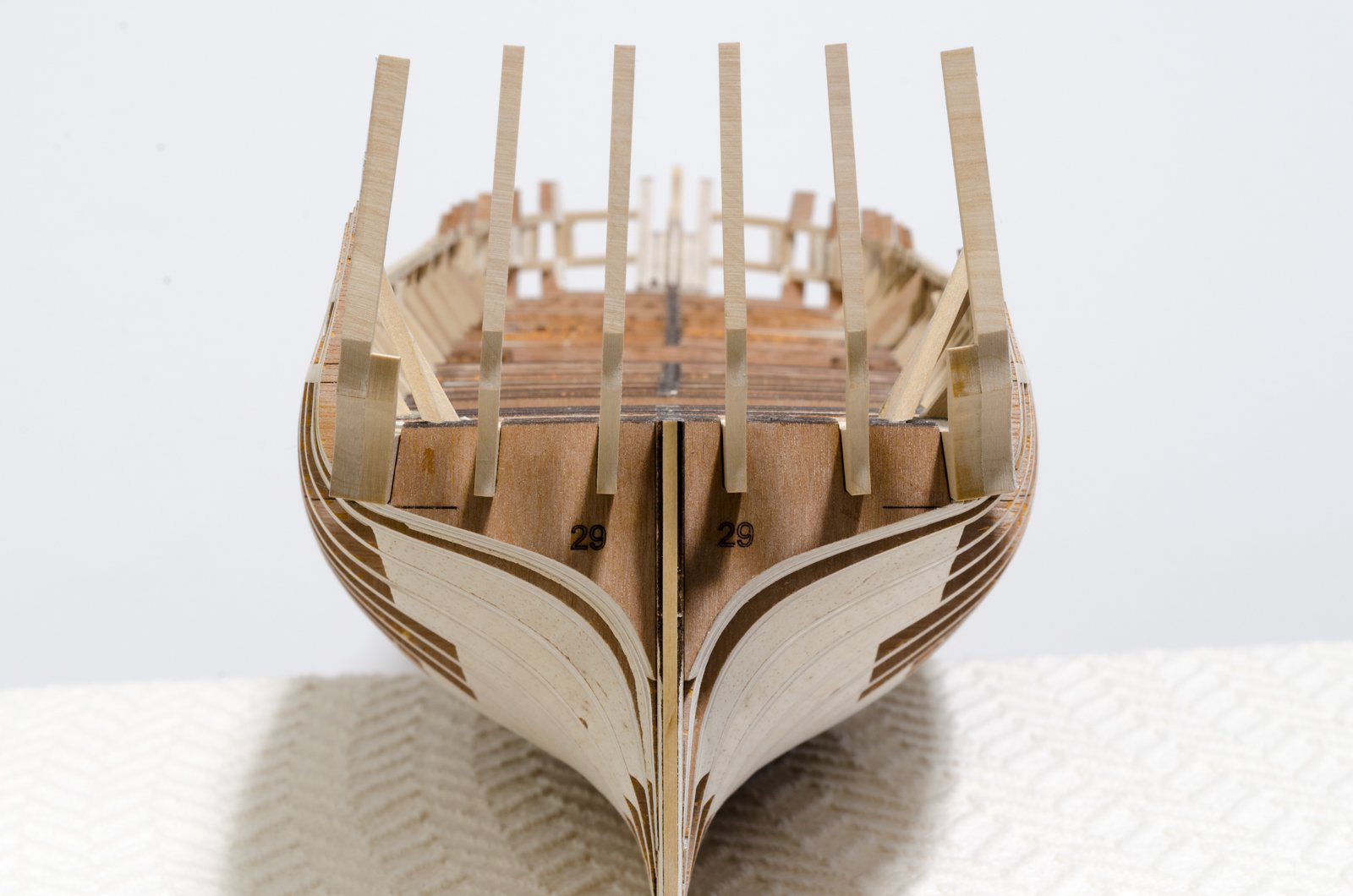
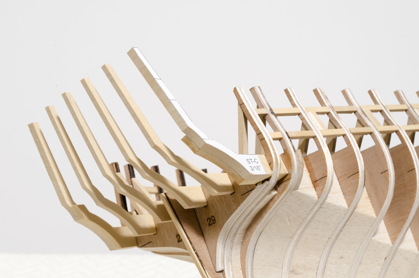
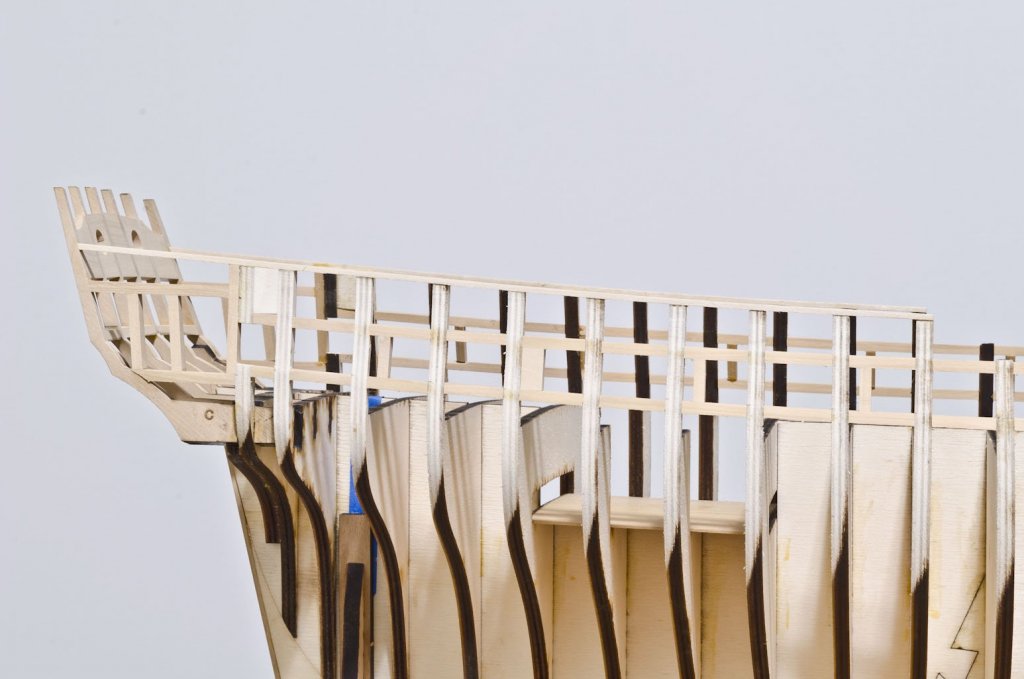
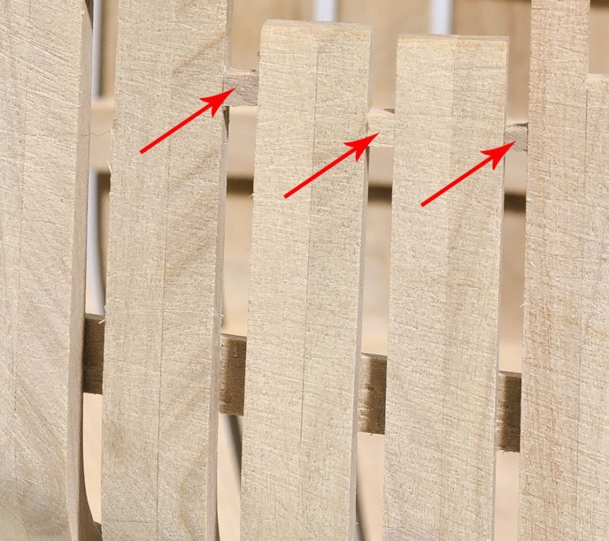
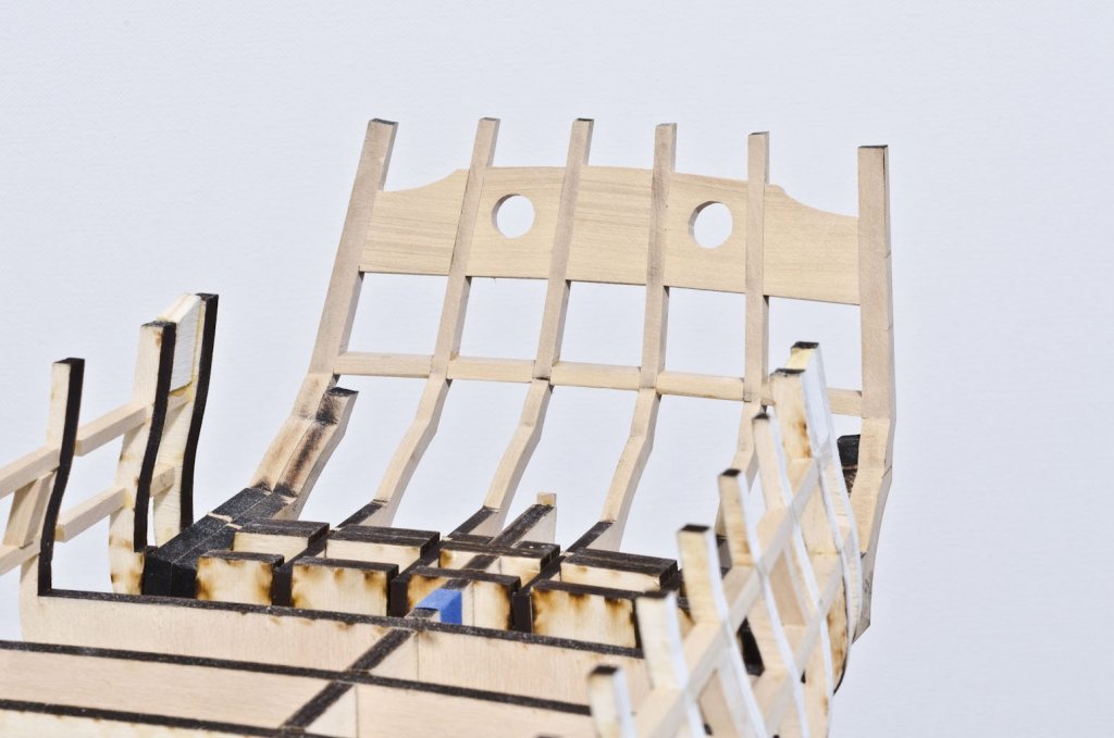
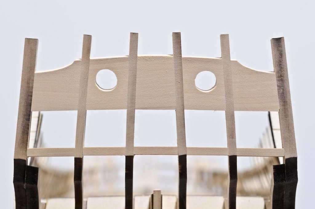
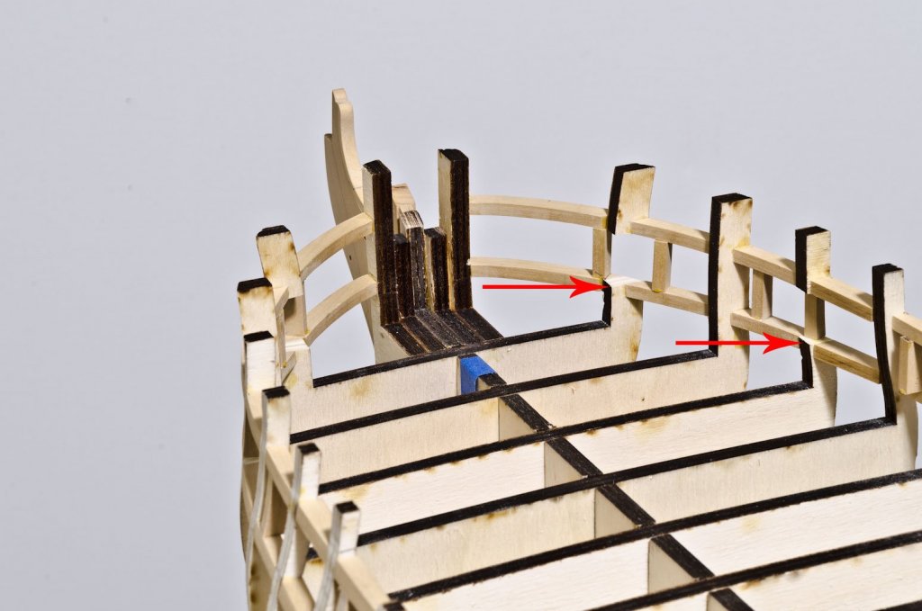
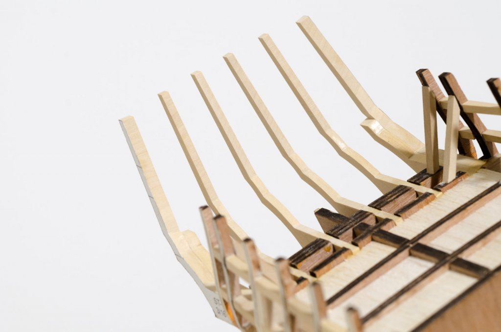
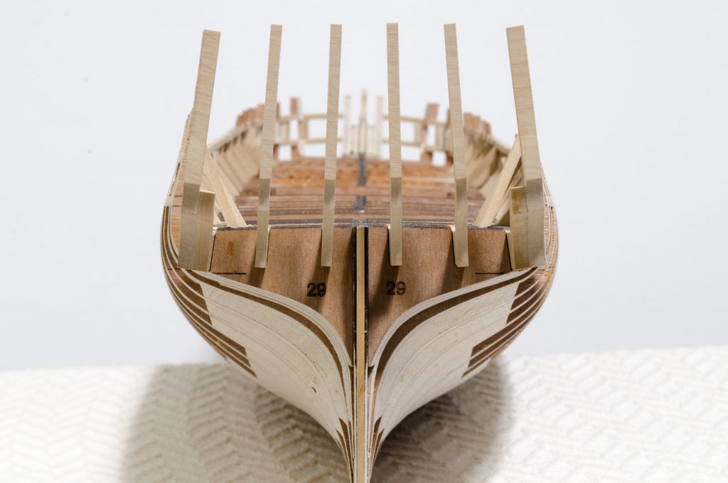
Building continues with the stern framing. I was lucky enough to get the frames laser cut for me. I used a simple cardboard template to install them at the same angle as shown on the plans. Next, the five sills were added. I made these from 5/32" x 5/16" strip. These angles were tricky to get right and there were a few throwaways. The sills were set flat, not pointing upwards. The final step was to add the four laser cut lintel filler pieces. In a few places, I found them to be a tiny bit too short between the frames, so I cut new ones from 1/4" sheet boxwood. The interior and exterior surfaces were then faired. I was told that these surfaces will eventually be thinned down even more. In preparation for the bollard timbers the area behind the stem was reduced to a thickness of 1/8". Mike

- 607 replies
-
- 33
-
-
- winchelsea
- Syren Ship Model Company
- (and 1 more)
-
Shawn, I started out using graphite paper as a transfer method. By the time I started work on the frames, I switched over to Elmer's School Glue and plan drawings which were made from a printed copy. There are times when graphite paper comes in handy, like when I transfer a scarph joint shape. So, both work, just depends on the application. Mike
-
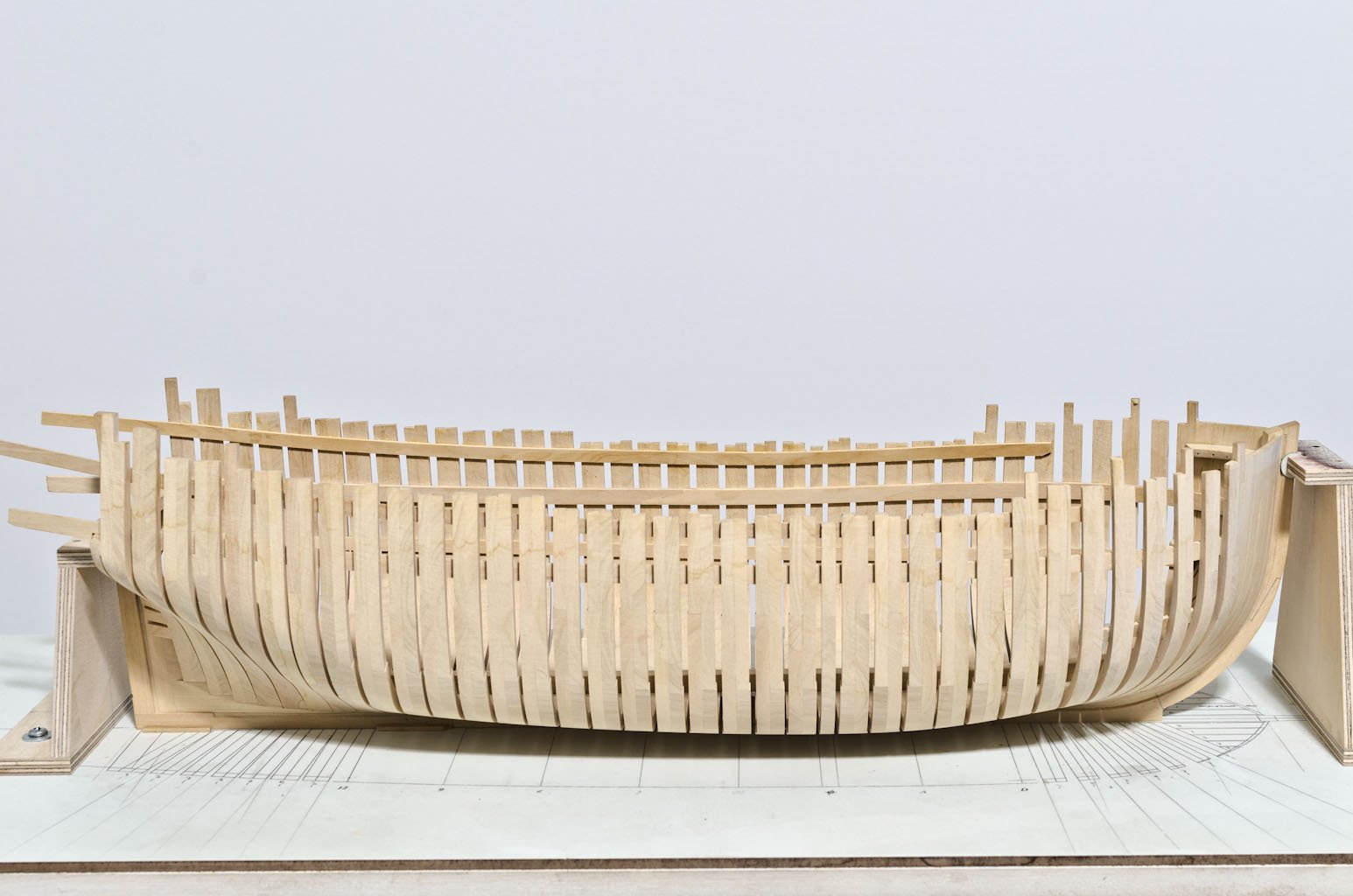
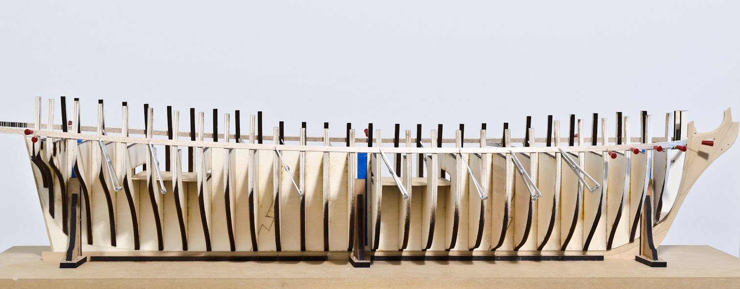
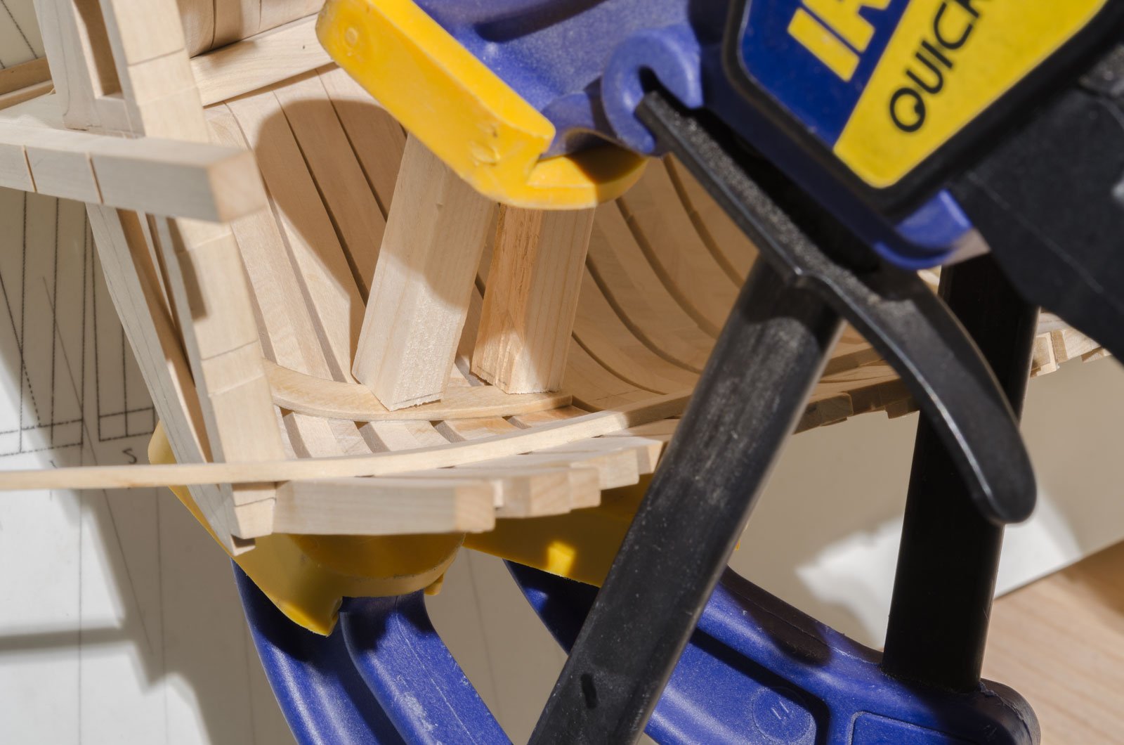
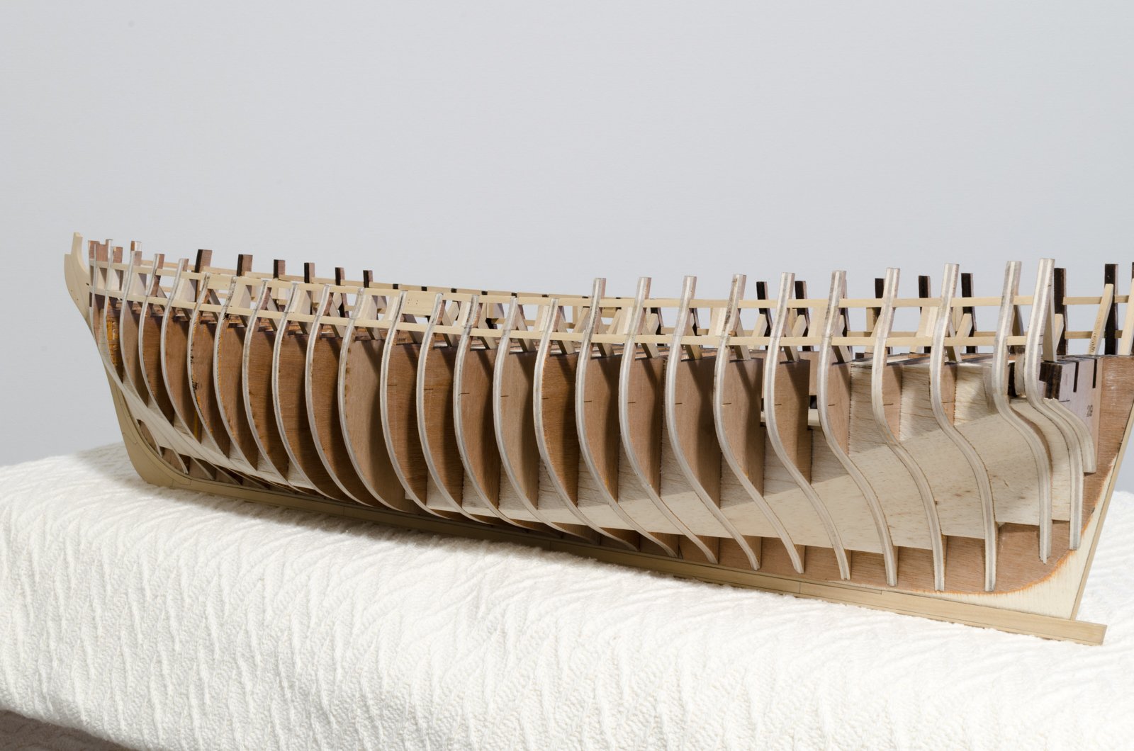
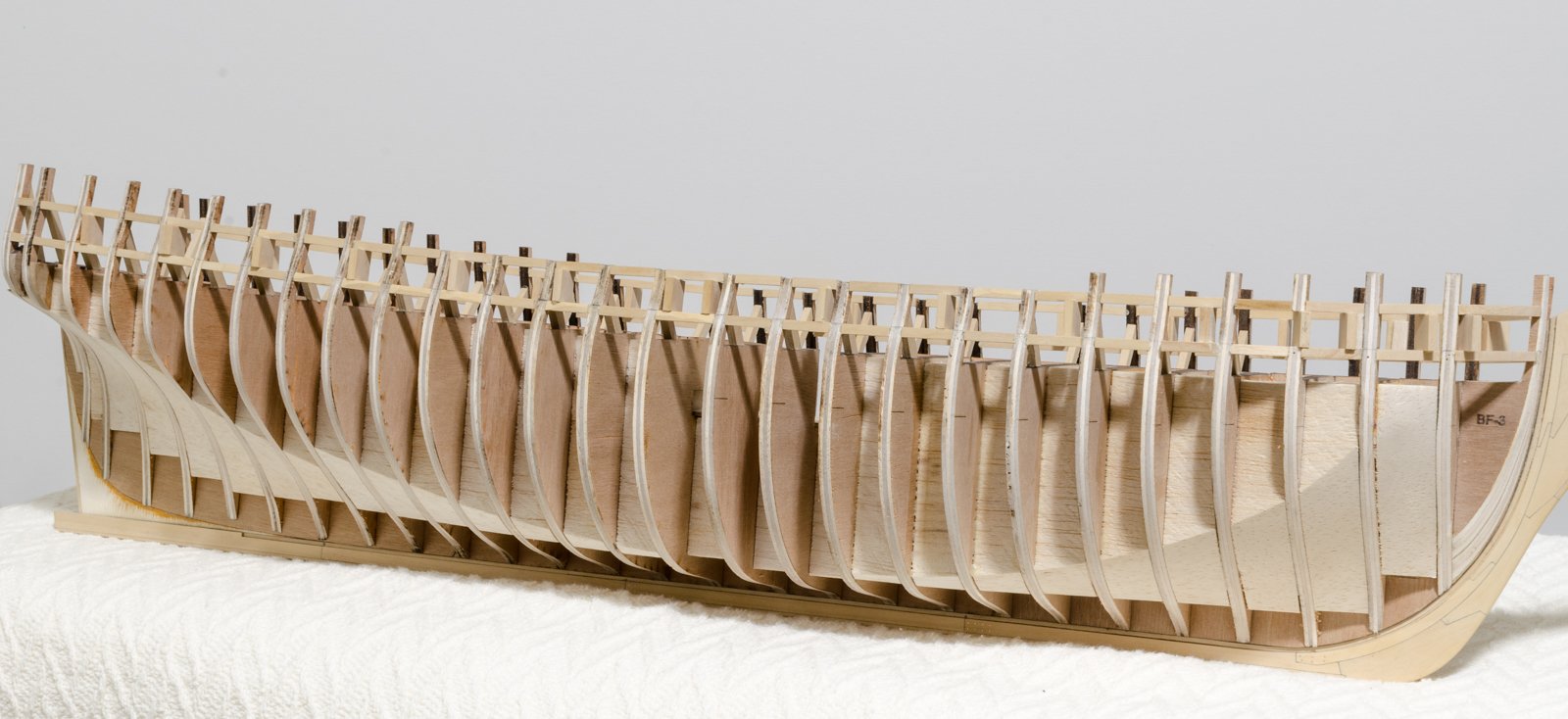
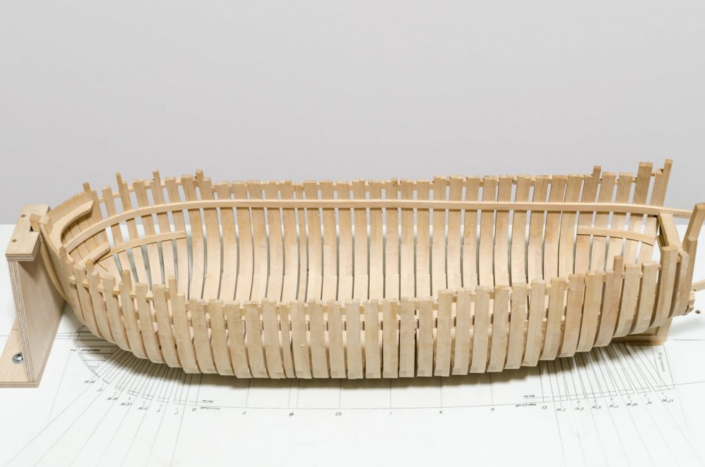
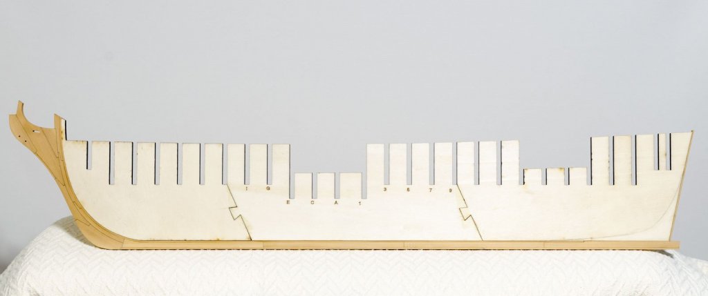
All of the work since my last post was done on the build board where the bulkhead former was held securely by the longitudinal channel and the three vertical supports. After adding the bulkheads, the hull was faired down to the half breadth in preparation for the gun port framing. I used a 36" x 1/16" x 1/4" x balsa strip as a batten to establish a smooth run for the framing. After completing one side, vertical measurements where taken at each bulkhead and transferred to the other side. The gun port framing and fixed block supports were added. This time, I drilled smaller 1/32" holes through the supports. Bulkheads had to be cut for proper gun port location at the bow. One of the two lower deck platforms installed. Mike


- 607 replies
-
- 25
-
-
- winchelsea
- Syren Ship Model Company
- (and 1 more)
-
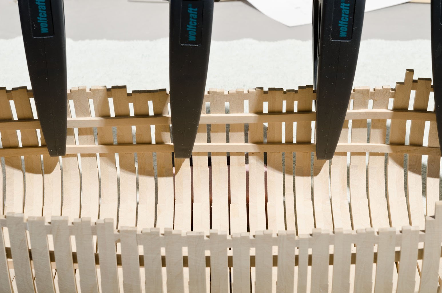
The ones I purchased open to 60mm and are 100mm long. Mike
-
Thank you, druxey! Clamp source: https://www.fruugo.us/wolfcraft-mt-70-precision-spring-clamp-clamping-width-max-7-cm/p-18753538-41049855 Mike
-
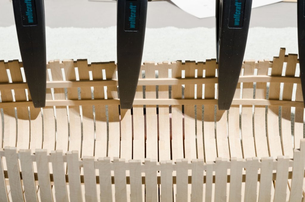
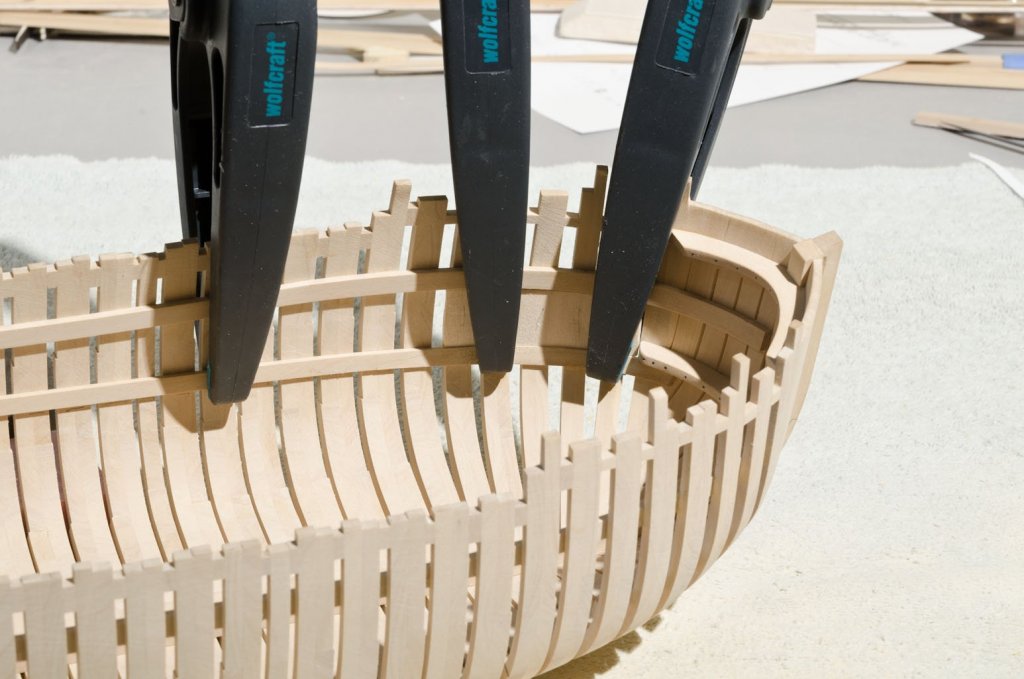
I just finished the port side platform clamp. The clamp was held in place with Wolfcraft clamps which can go deep into the hull. After gluing the aft end of the clamp, another balsa template was used to set the position of the forward end of the clamp. You'll notice that I have been fairing the exterior hull. For the most part it is done. Just need to do a bit more work at the stern. Also, I left a 1/2" or so of extra thickness at the top timbers. After the Forecastle deck clamp and stringer in the waist are attached I will final sand the top timbers to an even thickness along the hull. Mike
-
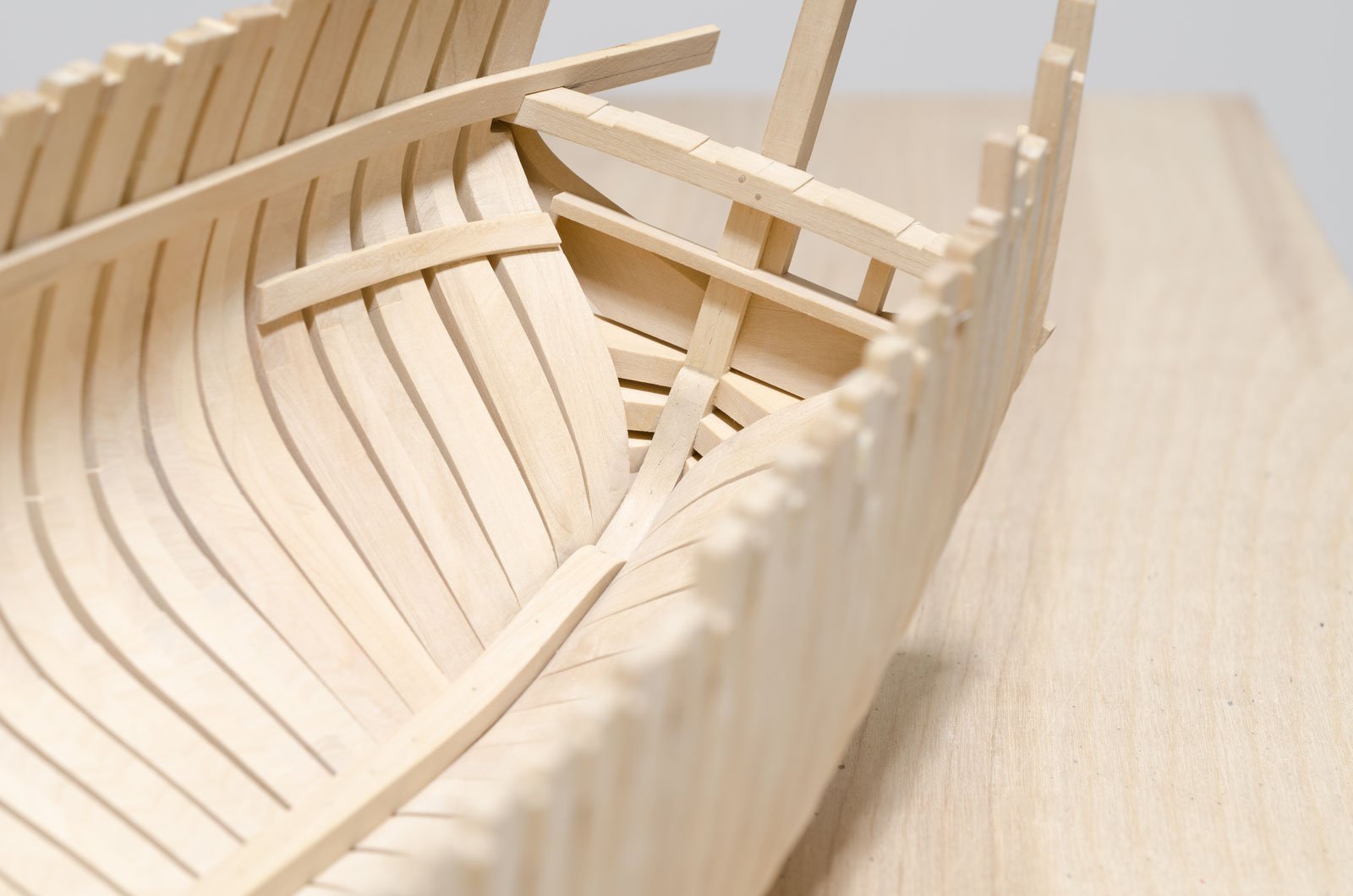
I thought it might be a good time to do some catching up. Hard to believe it's been 4 months since my last post. In preparation for adding the lower platform clamps, I installed a beam recessed to fit around the inner post. I will use this to align one edge of the aft platform clamp Only one side of the hull will be planked. The other side (open side) will only need two short clamps that represent the length of each platform both fore and aft. Measuring from the draught onto a balsa template made it easy to locate the lower platform position. Here is the aft platform clamp installed after using the same method. Clamping was tricky. I have actually made more progress than what is shown here. However, the lower platform clamp stills needs to be added on the planked side of the hull. I'm waiting for some deep reach clamps to arrive before I install it. This and more to come soon! Mike


-
Nope, the effort to correct the twist only led to more frustration. The new BF is a lot stiffer and stronger than the original. My plan is to keep it vertical during the gun port framing and planking above the wales. I will keep a watchful eye on it as I move ahead. Mike
- 607 replies
-
- 10
-
-
- winchelsea
- Syren Ship Model Company
- (and 1 more)
-
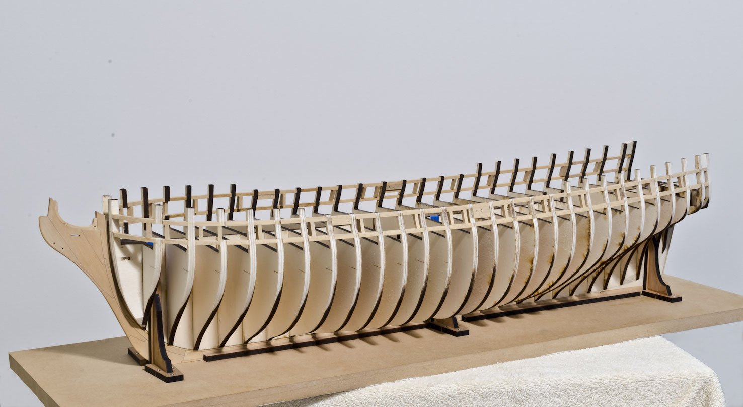
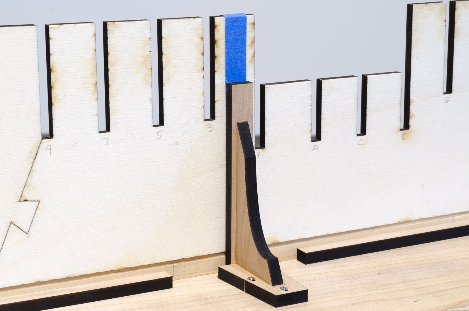
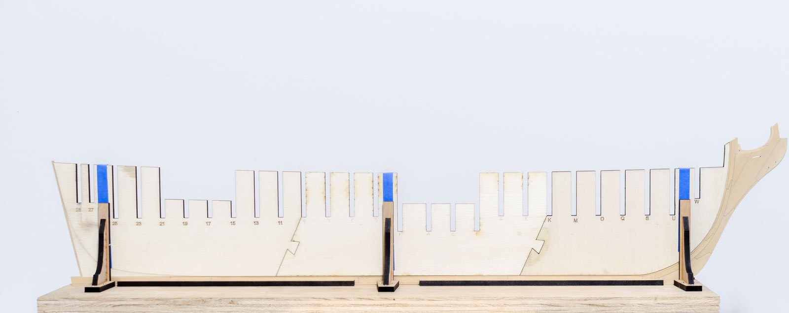
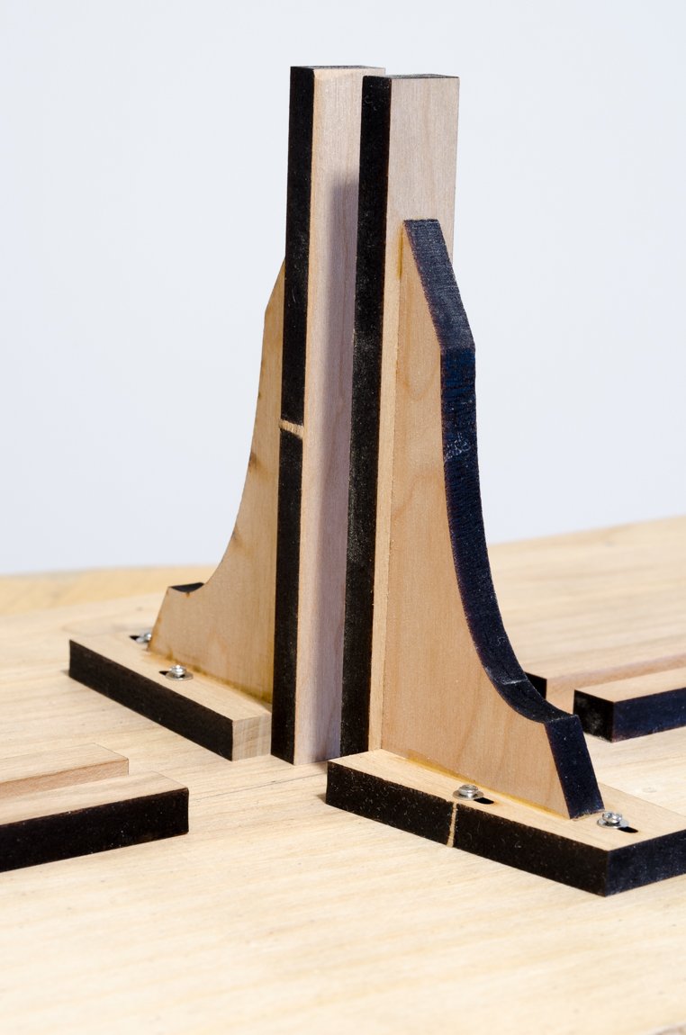
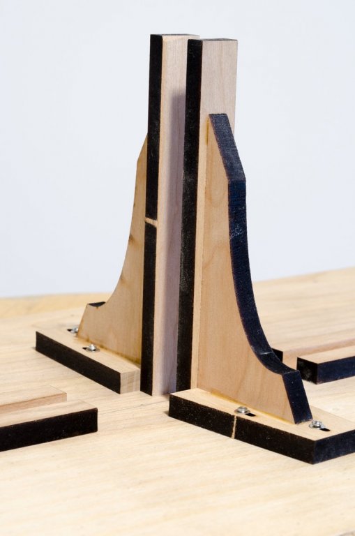
The bulkhead former will be held vertical while adding the bulkheads. Chuck designed these laser cut supports and longitudinal pieces from 1/4" stock. Laser char was removed from any area that will come in contact with the keel or lower stem. The slotted holes allow for some in and out movement. The bolts are M1.6 x 22 and the nuts are recessed into the bottom of the build board. They are secured with thin CA. Blue painters tape was used to make up any thickness variation between the keel and bulkhead former. Although the BF is held securely, it can be removed without loosening the supports. Mike


- 607 replies
-
- 17
-
-
- winchelsea
- Syren Ship Model Company
- (and 1 more)
-
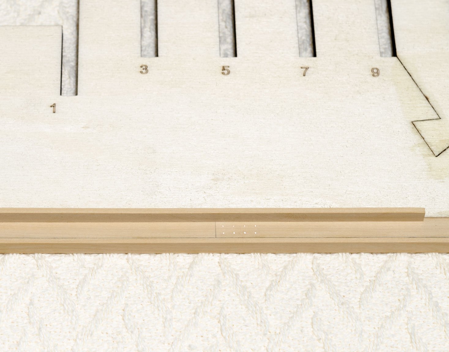
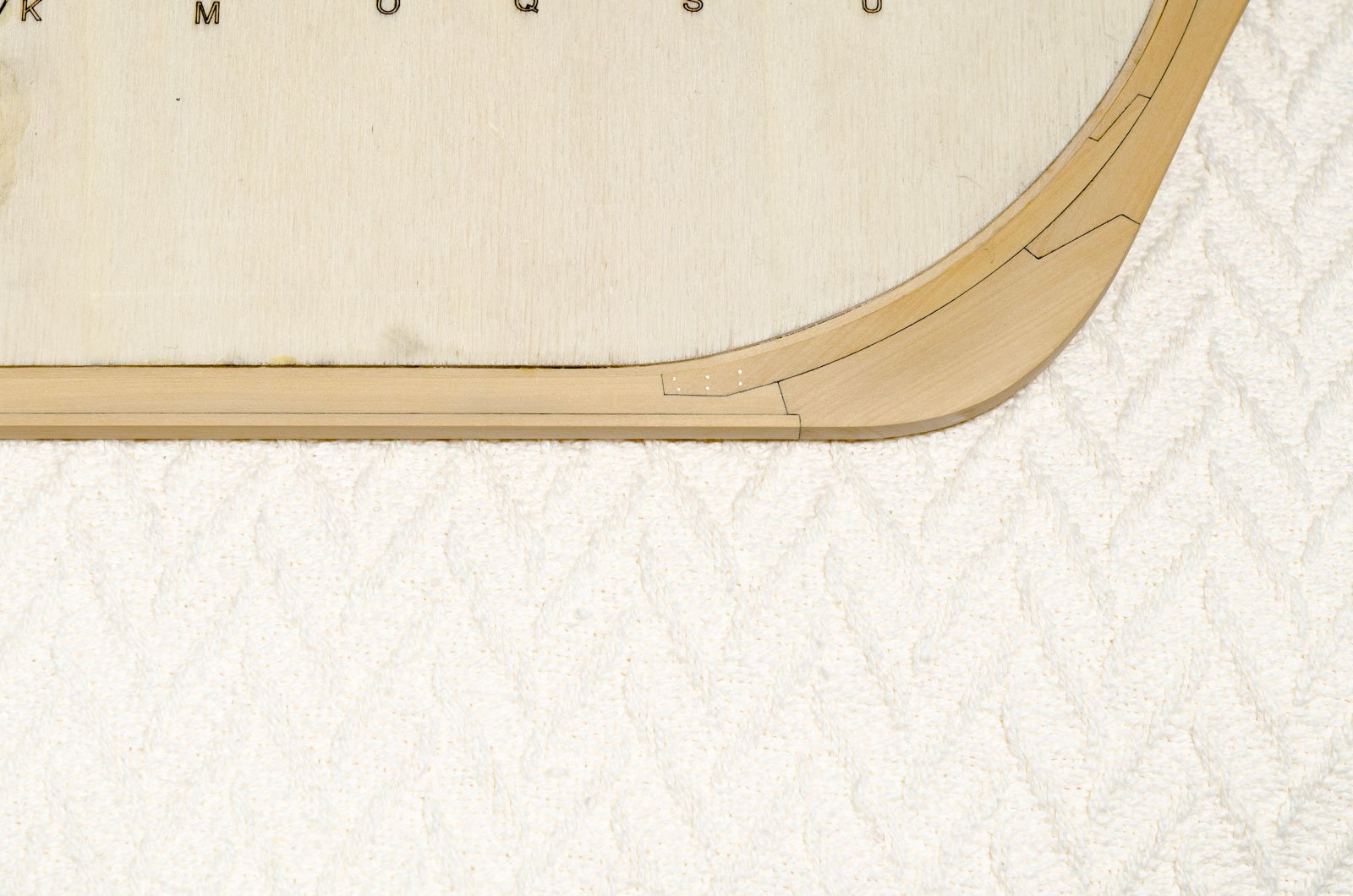
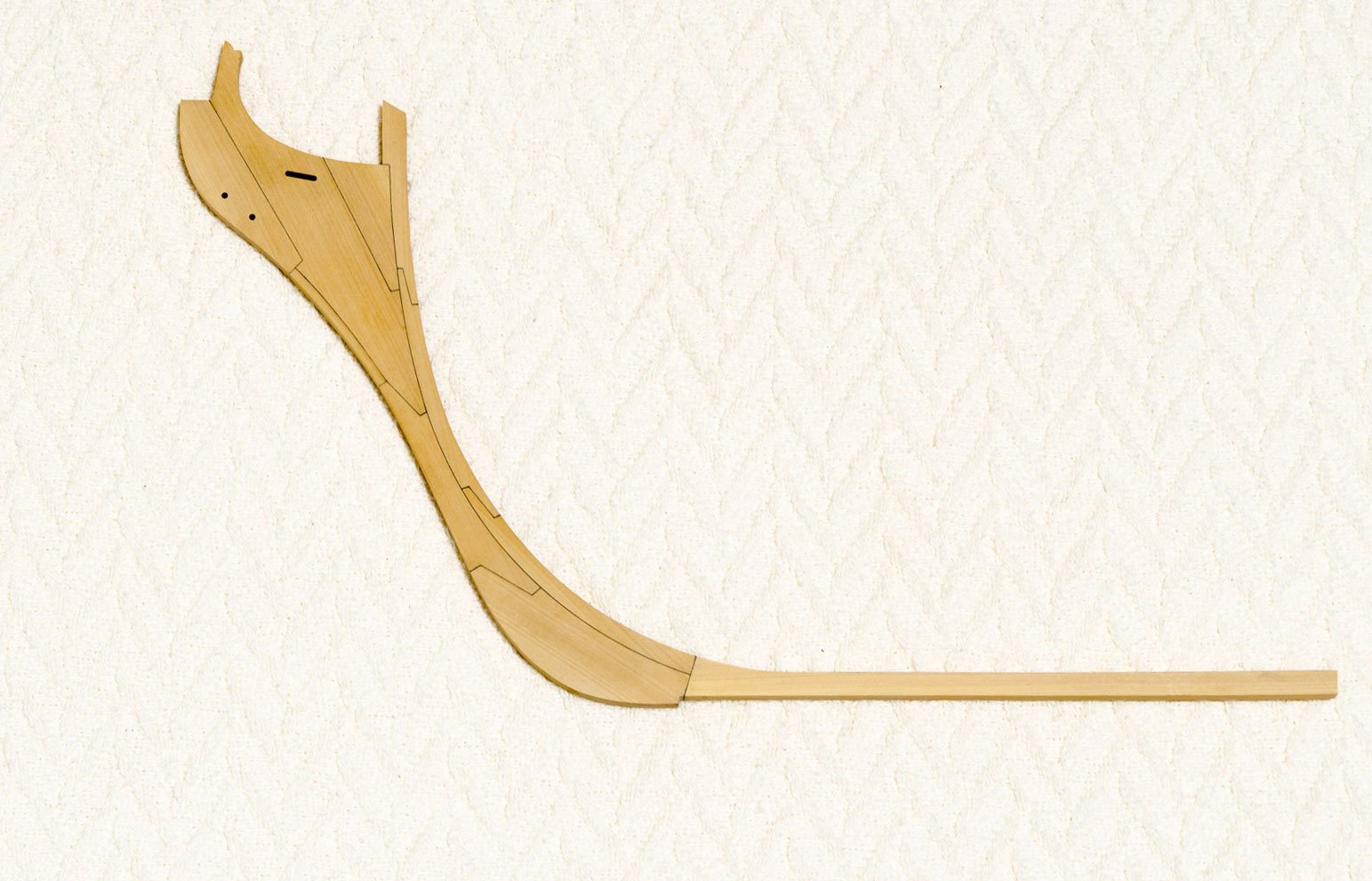
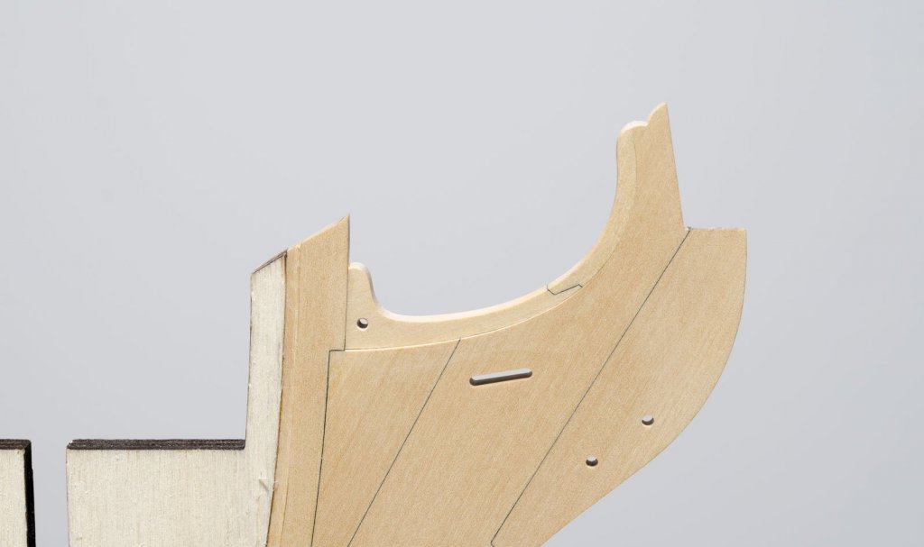
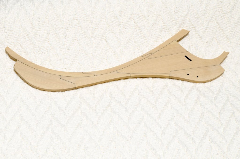
We had a great time at the Northeast Joint Clubs Conference last weekend. Lots of beautiful models on display. My girlfriend, Ofelia, did most of the picture taking. I Finally got to meet a number of MSW members while I was there which was really nice. Now that I'm back in build mode, I managed to taper the knee of the head and complete the gammoning knee and extension piece that sit above it. Templates were made from the plan drawings and transferred to 3/16" boxwood sheet. Mike
- 607 replies
-
- 22
-
-
- winchelsea
- Syren Ship Model Company
- (and 1 more)
-
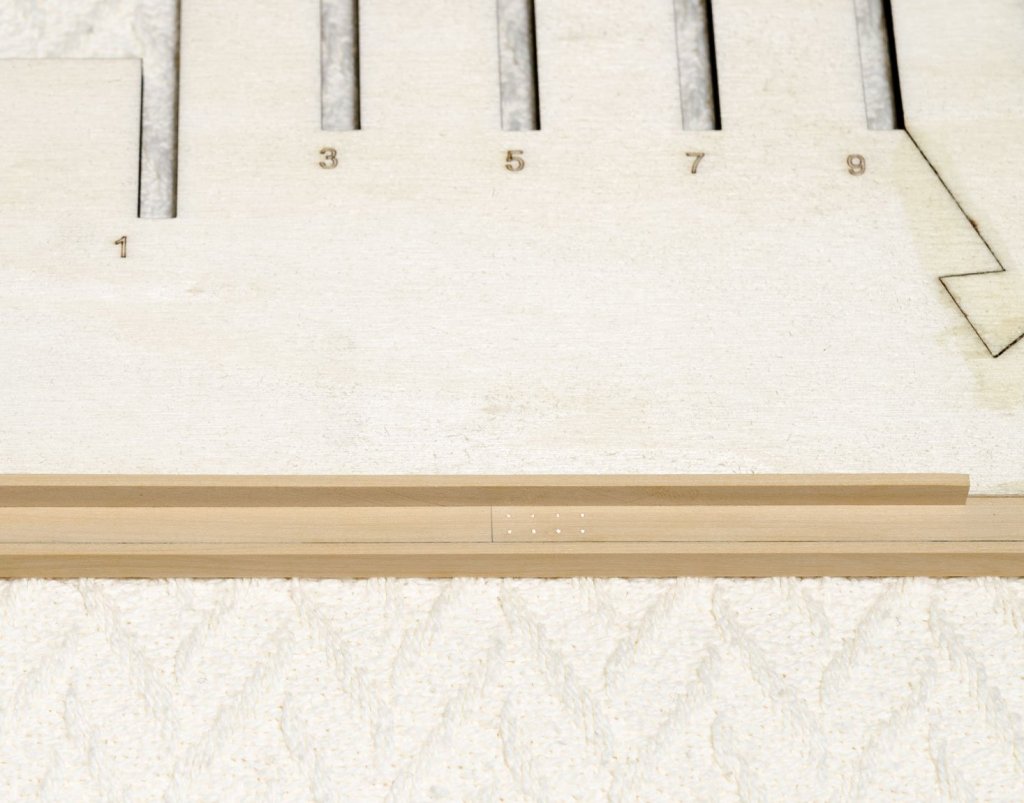
The three section bulkhead former is joined and the bearding line completed. The rabbet strip, knee assembly, keel sections and false keel sections have been added. 24 gauge copper wire was used for nailing the joints. Holes were drilled with a #76 drill bit (.020). This allows the wire to be inserted with a slight press fit into the holes. No gluing necessary. All of the keel joints were filed flush where the garboard plank will be. To do this I used an equaling file that is only 1/32" thick. http://www.ottofrei.com/Glardon-Vallorbe-Equalling-Special-Thickness-Precision-Files-LP1185?custcol19=14 I placed a plank along the upper edge of the keel to show the result. Mike

- 607 replies
-
- 24
-
-
- winchelsea
- Syren Ship Model Company
- (and 1 more)
-
Thanks, Chuck! Looks like I will have to order more wood to manage the larger scale. Mark, I too look forward to seeing what advantages the larger scale brings. Right now everything looks huge. I wasn't going to, but I finally decided do the box joint at the lower stem. Guess I was nervous about messing up what was already done. I spent most of the day on it and I'm really glad that it's done. Mike

- 607 replies
-
- 19
-
-
- winchelsea
- Syren Ship Model Company
- (and 1 more)
-
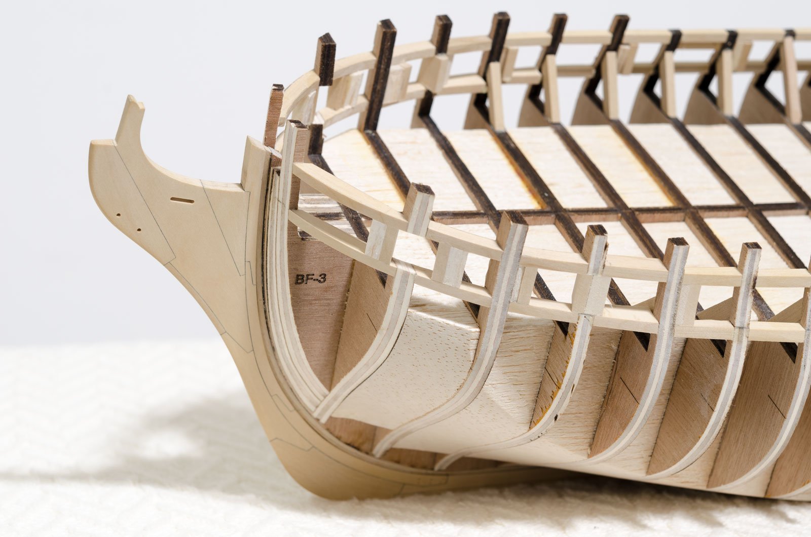
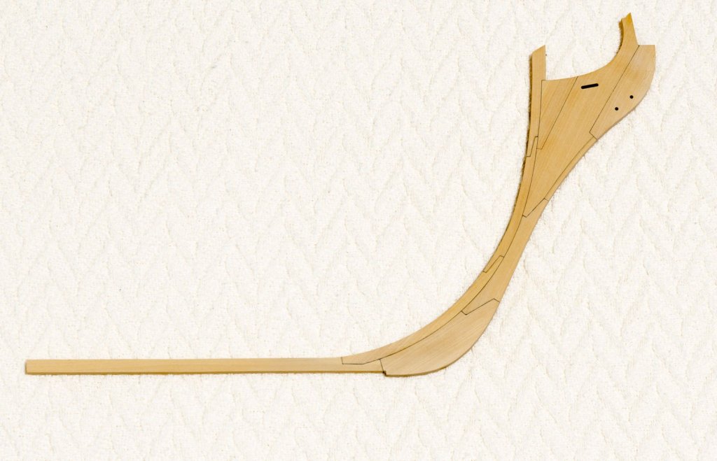
Work continues with the start of larger 1/4" scale Winchelsea. The stem has been scratch assembled using 1/4" boxwood sheet. It has been given a very light sanding (no tapering) to clean it up a bit for the photo. Mike
- 607 replies
-
- 27
-
-
- winchelsea
- Syren Ship Model Company
- (and 1 more)
-
Once I got started, it wasn't long before I realized that I couldn't untwist the hull without removing all the filler blocks and gun port framing. In hindsight I should have supported the stem and sternpost while doing the initial work. This is something I had done before, but for some reason didn't remember or see the need to do it here. Go figure! Anyway, after talking with Chuck, we decided to go up in scale. In the end I think it will show more detail and will look better at 1/4" scale. Mike
- 607 replies
-
- 13
-
-
- winchelsea
- Syren Ship Model Company
- (and 1 more)
-
Congratulations Maury! Very interesting build to follow and everything looks great. I didn't realize that it actually took you 2 1/2 years to finish. Any ideas as to where you are going from here? Mike
- 525 replies
-
- 2
-
-
- anchor hoy
- hoy
- (and 1 more)
-
Well, druxey, you are absolutely correct! I spotted it too while working on the stern frames. Steps are being taken now to fix this. I should have it done in a few days. Hopefully! Mike
- 607 replies
-
- 8
-
-
- winchelsea
- Syren Ship Model Company
- (and 1 more)
-
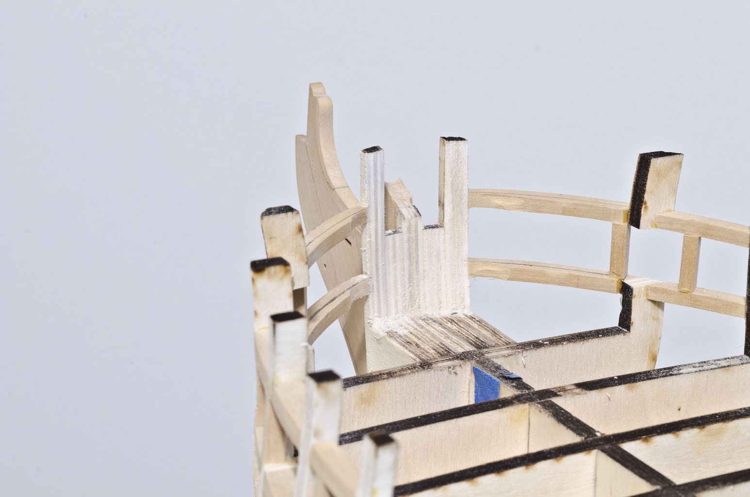
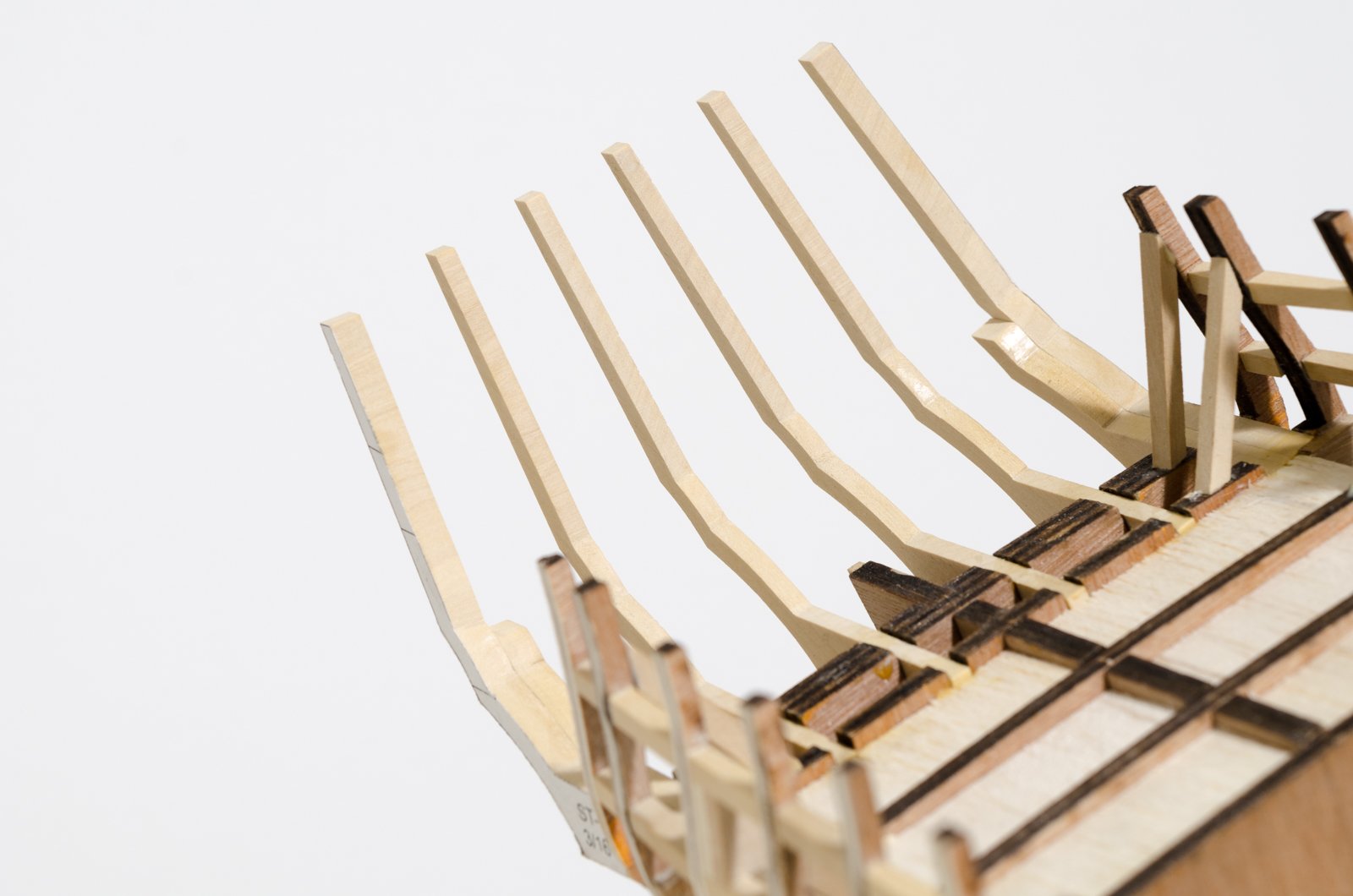
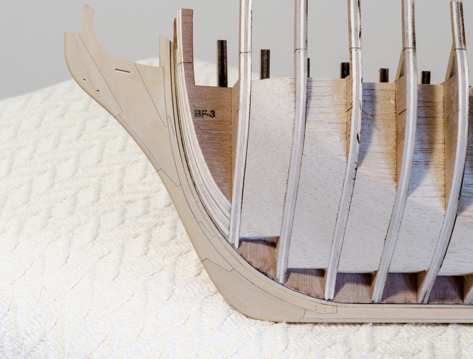
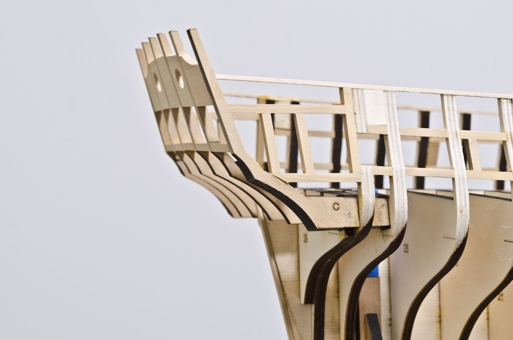
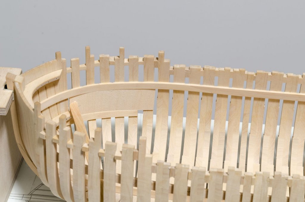
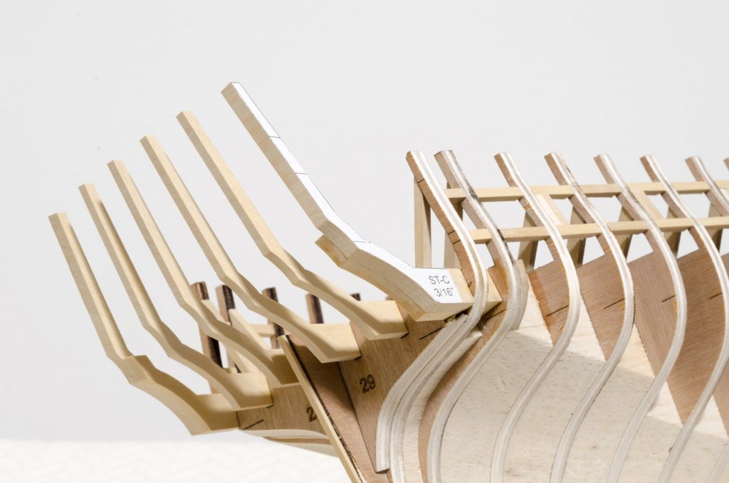
Thank you, Nils! All of the gun ports are now faired. I've started work on the stern framing. Again, I won't be using the laser cut kit parts. These six frames were cut from boxwood sheet. The slotted bulkheads allow for accurate placement of each frame, though it was necessary to make very slight adjustments to insure that the aft edges remained parallel to each other. Looking ahead, I can see that it would be easy to shift the frames out of position while adding the lower sills, lintels and Quarter Gallery Framing. I will keep a close eye on this. So far, things look good. Mike
- 607 replies
-
- 35
-
-

-
- winchelsea
- Syren Ship Model Company
- (and 1 more)
-
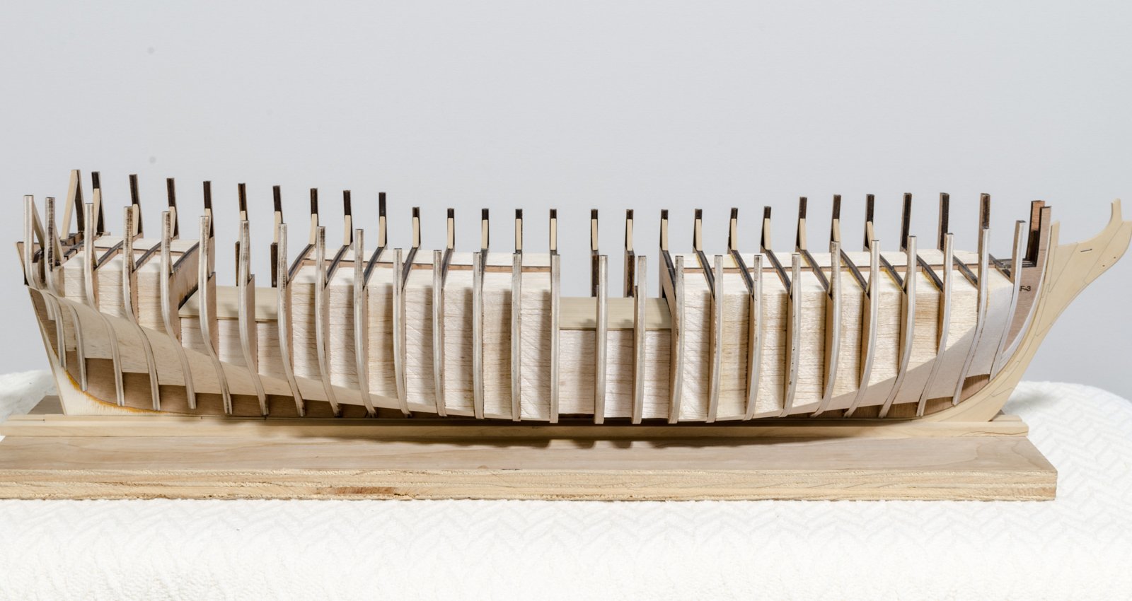
Thank you very much, Hubac'sHistorian and for all the "Likes". Moving ahead, I added the fixed block supports to the hull. Hard to believe that these would take several hours to make. Holes were drilled with a #70 drill. Once the blocks were in place I was ready to do a second fairing of the hull. One gun port upright loosened early on, so I decided to add basswood filler pieces between the gun ports and bulkhead extensions in order to strengthen the uprights. This will all be hidden later on. So far I have one side of the hull pretty much done. Mike


- 607 replies
-
- 41
-
-
- winchelsea
- Syren Ship Model Company
- (and 1 more)
-
Thank you for the kind words, Ken! I have been hard at work finishing up the gun port framing. Lots of different angles along with the usual throwaways. In some areas, like the last few stern ports, compound angles had to be used in order to get a good fit. Having a disc sander with angle adjustments made the work much easier. The few of the forward ports are set at different angles from the others. These angles where taken from an overhead view on one of the plan sheets. A balsa block was made on the disc sander to match the angle and width needed. It was glued in prior to adding the upright. On the same port the bulkhead extension was cut away to allow for the proper placement of the aft upright. Mike

- 607 replies
-
- 28
-
-
- winchelsea
- Syren Ship Model Company
- (and 1 more)
-
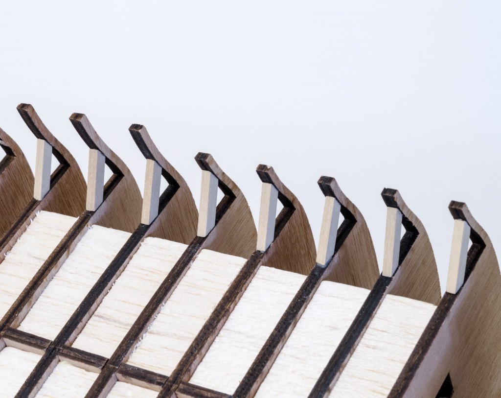
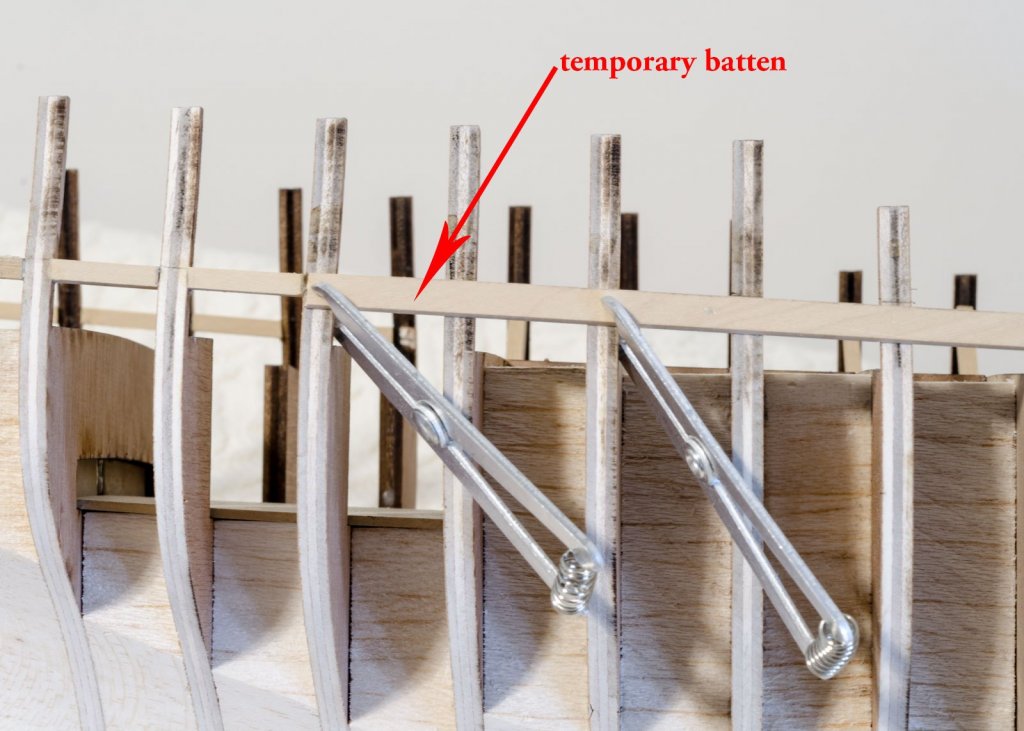
In preparation for fairing the hull I added some supports to the bulkhead extensions. Some of these are less than an 1/8" wide and are a too flexible, I think. Eventually they will be reduced to a 1/16", but not until some planking support is in place. Fairing the hull was straight forward using various sandpaper sticks along with a lot of batten checking. It will be faired again after the gun port sills and lintels are in. The bow filler pieces needed a lot of attention. The curve changes constantly as it moves up the stem and many checks with a batten were necessary to get the fit right. I also started work on the gun port sills. A batten was used to establish a smooth flow of sills along the hull while using the reference lines that are etched onto each bulkhead as a guide. Slight variances were visible once the batten was pinned to the hull. After making final adjustments, a sharp pencil was used along the top of the batten to draw the final sill locations on the edge of each bulkhead. The batten was then removed. When adding a gun port sill, a temporary batten was clamped to the opposite side of the hull. The top of the batten is flush with the sill locations drawn on each bulkhead. Though not shown here, I used a 3/8" wide cross-spall across the batten to the other side of the hull where the new sill was located. Pressing the sill to the cross-spall, while holding the cross-spall against the batten, flattens the upper edge of the sill parallel to the other side. Mike


- 607 replies
-
- 30
-
-
- winchelsea
- Syren Ship Model Company
- (and 1 more)
-
Sounds familiar, Greg! Though I found it easy enough to hold the plank tip into the rabbet using carpenters glue, until set, instead of using CA. Mike